WO2022135465A1 - 一种连通装置、该连通装置的制造方法以及热管理组件 - Google Patents
一种连通装置、该连通装置的制造方法以及热管理组件 Download PDFInfo
- Publication number
- WO2022135465A1 WO2022135465A1 PCT/CN2021/140436 CN2021140436W WO2022135465A1 WO 2022135465 A1 WO2022135465 A1 WO 2022135465A1 CN 2021140436 W CN2021140436 W CN 2021140436W WO 2022135465 A1 WO2022135465 A1 WO 2022135465A1
- Authority
- WO
- WIPO (PCT)
- Prior art keywords
- plate body
- channel
- plate
- communication
- communication device
- Prior art date
- Legal status (The legal status is an assumption and is not a legal conclusion. Google has not performed a legal analysis and makes no representation as to the accuracy of the status listed.)
- Ceased
Links
Images



Classifications
-
- B—PERFORMING OPERATIONS; TRANSPORTING
- B60—VEHICLES IN GENERAL
- B60H—ARRANGEMENTS OF HEATING, COOLING, VENTILATING OR OTHER AIR-TREATING DEVICES SPECIALLY ADAPTED FOR PASSENGER OR GOODS SPACES OF VEHICLES
- B60H1/00—Heating, cooling or ventilating devices
- B60H1/00507—Details, e.g. mounting arrangements, desaeration devices
- B60H1/00557—Details of ducts or cables
- B60H1/00571—Details of ducts or cables of liquid ducts, e.g. for coolant liquids or refrigerants
-
- B—PERFORMING OPERATIONS; TRANSPORTING
- B60—VEHICLES IN GENERAL
- B60H—ARRANGEMENTS OF HEATING, COOLING, VENTILATING OR OTHER AIR-TREATING DEVICES SPECIALLY ADAPTED FOR PASSENGER OR GOODS SPACES OF VEHICLES
- B60H1/00—Heating, cooling or ventilating devices
- B60H1/00321—Heat exchangers for air-conditioning devices
- B60H1/00342—Heat exchangers for air-conditioning devices of the liquid-liquid type
-
- B—PERFORMING OPERATIONS; TRANSPORTING
- B60—VEHICLES IN GENERAL
- B60H—ARRANGEMENTS OF HEATING, COOLING, VENTILATING OR OTHER AIR-TREATING DEVICES SPECIALLY ADAPTED FOR PASSENGER OR GOODS SPACES OF VEHICLES
- B60H1/00—Heating, cooling or ventilating devices
- B60H1/00485—Valves for air-conditioning devices, e.g. thermostatic valves
-
- B—PERFORMING OPERATIONS; TRANSPORTING
- B60—VEHICLES IN GENERAL
- B60H—ARRANGEMENTS OF HEATING, COOLING, VENTILATING OR OTHER AIR-TREATING DEVICES SPECIALLY ADAPTED FOR PASSENGER OR GOODS SPACES OF VEHICLES
- B60H1/00—Heating, cooling or ventilating devices
- B60H1/00507—Details, e.g. mounting arrangements, desaeration devices
-
- B—PERFORMING OPERATIONS; TRANSPORTING
- B60—VEHICLES IN GENERAL
- B60H—ARRANGEMENTS OF HEATING, COOLING, VENTILATING OR OTHER AIR-TREATING DEVICES SPECIALLY ADAPTED FOR PASSENGER OR GOODS SPACES OF VEHICLES
- B60H1/00—Heating, cooling or ventilating devices
- B60H1/32—Cooling devices
- B60H1/3204—Cooling devices using compression
- B60H1/3229—Cooling devices using compression characterised by constructional features, e.g. housings, mountings, conversion systems
-
- F—MECHANICAL ENGINEERING; LIGHTING; HEATING; WEAPONS; BLASTING
- F28—HEAT EXCHANGE IN GENERAL
- F28F—DETAILS OF HEAT-EXCHANGE AND HEAT-TRANSFER APPARATUS, OF GENERAL APPLICATION
- F28F9/00—Casings; Header boxes; Auxiliary supports for elements; Auxiliary members within casings
- F28F9/02—Header boxes; End plates
- F28F9/04—Arrangements for sealing elements into header boxes or end plates
- F28F9/16—Arrangements for sealing elements into header boxes or end plates by permanent joints, e.g. by rolling
- F28F9/18—Arrangements for sealing elements into header boxes or end plates by permanent joints, e.g. by rolling by welding
-
- F—MECHANICAL ENGINEERING; LIGHTING; HEATING; WEAPONS; BLASTING
- F25—REFRIGERATION OR COOLING; COMBINED HEATING AND REFRIGERATION SYSTEMS; HEAT PUMP SYSTEMS; MANUFACTURE OR STORAGE OF ICE; LIQUEFACTION SOLIDIFICATION OF GASES
- F25B—REFRIGERATION MACHINES, PLANTS OR SYSTEMS; COMBINED HEATING AND REFRIGERATION SYSTEMS; HEAT PUMP SYSTEMS
- F25B2500/00—Problems to be solved
- F25B2500/18—Optimization, e.g. high integration of refrigeration components
Definitions
- the present invention relates to the technical field of vehicle thermal management, in particular to a communication device, a manufacturing method of the communication device, and a thermal management assembly.
- the vehicle thermal management system includes components such as heat exchangers, valve devices, and accumulators.
- the above components are usually connected to the system through pipelines, or integrated by installing the above components into one connection.
- the connecting part is usually formed by machining, but it is difficult to form a complex spatial flow channel.
- the purpose of the present invention is to provide a communication device, a method for processing the communication device, and a thermal management assembly, the communication device can be used to form a complex space channel, meet the layout requirements of different devices, reduce the location limitation of the device layout, and have relatively good applicability.
- a communication device can be used for a thermal management assembly
- the communication device comprises two or more plate bodies, the adjacent said plate bodies are fixed and connected in a sealed manner, the communication device has a channel, and the adjacent said plates
- the interior of at least one of the bodies is provided with at least part of at least one channel portion, and the adjacent plate bodies form the channel at the channel portion;
- One of the side walls of the plate body is provided with a mounting portion and/or a communication portion, the mounting portion is provided with a mounting hole, and the thermal management assembly includes a valve device capable of controlling the flow rate or communication of the passage.
- At least part of the valve device is located in the installation hole, the channel is arranged in communication with at least one of the installation holes of the installation part; the communication part has a communication hole, and the thermal management assembly further includes a thermal management unit, at least one of the inlet or outlet of one of the thermal management units can communicate with the communication hole, and the channel is arranged in communication with at least one of the communication holes.
- the present invention also provides a thermal management assembly, the thermal management assembly includes a communication device, a thermal management unit and a valve device; the thermal management unit includes at least one of a heat exchange part and a liquid reservoir; the valve device It includes at least one of a throttling element, a solenoid valve, and a switching valve; the communication device includes two or more plate bodies, and the adjacent plate bodies are fixed and sealed in a sealed connection, the communication device has a channel, and the adjacent plate bodies are connected.
- the interior of at least one of the plate bodies is provided with at least one channel portion, and the adjacent plate bodies form the channel at the channel portion;
- One of the side walls of the plate body is provided with an installation part and/or a communication part;
- the installation part has an installation hole, at least part of the valve device is located in the installation hole,
- the communication part has a communication hole, at least part of the thermal management unit The inlet or outlet is communicated with the communication hole.
- the present invention also provides a manufacturing method of the communication device, comprising the following steps:
- the mounting portion of the plate body is processed to form mounting holes and/or the communicating portion is processed to form communication holes.
- a communication device provided in the above technical solution is provided by setting more than two plate bodies, and the adjacent plate bodies are fixed and sealed, and at least one channel portion is provided in at least one of the adjacent plate bodies, and also through the A channel is provided, the adjacent plate bodies form a channel at the channel portion, and a mounting portion and/or a communicating portion provided along one of the side walls of the at least one plate body in the axial or radial direction of the communication device, the mounting portion is provided with a mounting portion a hole, the channel is arranged in communication with the installation hole of the installation part, and part of the valve device is located in the installation hole; the communication part has a communication hole, and at least part of the inlet or outlet of the thermal management unit is communicated with the communication hole, so that the valve device is used for connecting the valve device based on the installation part It is installed on the plate body, and a mounting hole is arranged on the mounting part, so that the channel is communicated with the valve device through the mounting hole, and the communication part has a communication hole, and the communication hole is
- FIG. 1 is a perspective structural schematic diagram of the communication device shown in Embodiment 1 of the present invention from one perspective;
- FIG. 2 is a schematic three-dimensional structural diagram of the communication device shown in FIG. 1 from another perspective;
- Fig. 3 is the top-view structure schematic diagram of the communication device shown in Fig. 2;
- Fig. 4 is the cross-sectional structure schematic diagram of the communication device shown in Fig. 3 at A-A;
- Fig. 5 is the enlarged structural schematic diagram of B shown in Fig. 4;
- FIG. 6 is a schematic three-dimensional structure diagram of the first plate body obtained in step S1 in the method for processing the communication device shown in FIG. 1;
- step S1 is a schematic three-dimensional structural diagram of the second plate body obtained in step S1 in the method for processing the communication device shown in FIG. 1;
- step S1 is a schematic three-dimensional structure diagram of the third plate body obtained in step S1 in the method for processing the communication device shown in FIG. 1;
- FIG. 9 is a schematic three-dimensional structure diagram of the fourth plate body obtained in step S1 in the method for processing the communication device shown in FIG. 1;
- FIG. 10 is a schematic three-dimensional structural diagram of a viewing angle of the fifth plate body obtained in step S1 in the method for processing the communication device shown in FIG. 1;
- FIG. 11 is a schematic three-dimensional structural diagram of the fifth plate body shown in FIG. 10 from another perspective;
- FIG. 12 is a schematic structural diagram of sequentially stacking each plate body in step S2 in the method for processing the communication device shown in FIG. 1;
- FIG. 13 is a schematic three-dimensional structural diagram of a viewing angle after each plate body is welded in step S2 in the method for processing the communication device shown in FIG. 1;
- FIG. 14 is a schematic three-dimensional structure diagram of another viewing angle after each plate body shown in FIG. 13 is welded;
- FIG. 16 is a schematic three-dimensional structure diagram of the communication device shown in Embodiment 3 of the present invention.
- Figure 17 is an enlarged schematic view of the structure at C shown in Figure 16;
- Figure 18 is an exploded schematic view of the communication device shown in Figure 16;
- FIG. 19 is a perspective structural schematic diagram of the communication device shown in Embodiment 4 of the present invention from one perspective;
- Fig. 20 is an exploded schematic view of each plate body and each solder layer in the communication device shown in Fig. 19;
- FIG. 21 is a schematic three-dimensional structural diagram of the communication device shown in FIG. 20 from another perspective;
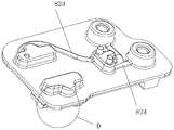
- FIG. 22 is an enlarged schematic view of the structure at D shown in FIG. 21 .
- an embodiment of the present invention provides a communication device, which can be used in a thermal management assembly.
- the communication device includes two or more plates, and the adjacent plates are fixed and sealed.
- the communication device has a channel, at least one channel portion is provided inside at least one of the adjacent plate bodies, and the adjacent plate bodies form a channel at the channel portion; wherein, along the axial or radial direction of the communication device, at least one plate One of the side walls of the body is provided with a mounting portion and/or a communicating portion, and the mounting portion is provided with a mounting hole
- the thermal management assembly includes a valve device, the valve device can control the flow or on-off of the channel, and at least part of the valve device is located in the mounting hole , the channel is arranged in communication with the installation hole of at least one installation part; the communication part has a communication hole, and the thermal management assembly also includes a thermal management unit, one of the inlet or outlet of the at least one thermal management unit can be communicated with the communication hole, and the channel
- the installation part is used to install the valve device on the plate body, and at the same time, the installation part is provided with installation holes, so that the channel communicates with the valve device through the installation hole, and the communication part has a communication hole, and the communication hole is connected with the inlet or outlet of the thermal management unit.
- the fluid medium flows through the channel and the corresponding device. Since there are more than two plates, the adjacent plates form at least a part of the channel at the channel portion, and the channel can be formed by at least two channel portions. The internal space of the channel can be stored, and more fluid media can be stored.
- the communication device can form a complex space channel, which can be used to set valve devices and thermal management units in multiple thermal management components, and meet the different requirements of different devices. Layout requirements, so that the layout of the device is not restricted by the location, and the utilization rate of the internal space is improved.
- the above-mentioned plate body can be made of aluminum alloy or other materials.
- at least one of the adjacent plate bodies can be coated with a composite welding layer on the connecting surface, so that the plate body provided with the composite welding layer is welded to its adjacent plate body.
- Fixed, or a solder layer can be provided between two adjacent boards, and the adjacent boards can be welded and fixed through the solder layer.
- the aforementioned fluid medium may be a refrigerant, a cooling liquid, or a cooling oil, etc. used in a vehicle thermal management system.
- the same channel can be formed by connecting and surrounding a plurality of adjacent corresponding channel parts.
- the same channel can be formed by the channel parts provided in two plate bodies, three plate bodies, or four plate bodies to form part of the channel side wall.
- different channels in the communication device may be composed of different numbers and/or the same number of plates.
- the communication device contains five plates, and one channel may be formed by the channel portion between the two plates. part of the side wall, and another channel may form part of the side wall of the channel by the channel portion provided in the three plates.
- one of the side walls of at least one plate body is provided with a mounting portion and/or a communication portion, for example, along the axial direction of the communication device, one side wall of one plate body is provided with a mounting portion and/or a communication portion.
- the installation part is provided with a installation hole
- part of the valve device is arranged in the installation
- the channel is arranged in communication with the installation hole
- the communication part has a communication hole
- the inlet or outlet of the thermal management unit is arranged in communication with the communication hole
- the communication hole is arranged in communication with the channel;
- the two side walls of the two plates are provided with two mounting portions, and each side wall is provided with a corresponding mounting portion, and the mounting portion is provided with mounting holes, and each mounting hole is provided with a mounting portion.
- a corresponding part of the valve device is provided.
- the communication device includes five plates, from top to bottom, the plates are defined as a first plate 1a, a second plate 2a, and a third plate 3a , the fourth plate body 4a and the fifth plate body 5a, the second plate body 2a is located between the first plate body 1a and the third plate body 3a, the fourth plate body 4a is located between the third plate body 3a and the fifth plate body 5a
- the channel parts of the second plate body 2a and the fourth plate body 4a are all through grooves 7a
- the channel part of the first plate body 1a and the channel part of the fifth plate body 5a are both grooves 6a
- the third plate body 3a includes two channel parts, the two channel parts of the third plate body 3a are grooves 6a, one of the grooves 6a of the third plate body 3a is defined as the first groove 61a, and the other groove 6a is the second groove 6a.
- the groove 62a, the channel 8 includes a first channel 81a and a second channel 82a, the groove 6a of the first plate 1a, the through groove 7a of the second plate 2a and the first groove 61a of the third plate 3a form the first groove 62a.
- a channel 81a, the second groove 62a of the third plate body 3a, the through groove 7a of the fourth plate body 4a and the groove 6a of the fifth plate body 5a form the second channel 82a, the second plate body 2a is in contact with the first plate body 2a.
- the connecting surfaces of the board 1a and the third board 3a are coated with composite welding layers, and the connecting surfaces of the fourth board 4a with the third board 3a and the fifth board 5a are coated with composite welding layers.
- only a part of the second plate body 2a may be located between the first plate body 1a and the third plate body 3a, and only a part of the fourth plate body 4a may be located between the third plate body 3a and the fifth plate body 5a between.
- the groove 6a of the first plate body 1a, the through groove 7a of the second plate body 2a and the first groove 61a of the third plate body 3a form the first channel 81a, as shown in FIG. 1 .
- the shape of the through groove 7a of the second plate body 2a is the same as that of the first channel 81a, the number of the first channel 81a is one, and the first channel 81a is arc-shaped.
- the second groove 62a of the third plate body 3a, the through groove 7a of the fourth plate body 4a, and the groove 6a of the fifth plate body 5a form a second channel 82a.
- the fourth plate body The shape of the through groove 7a of 4a is the same as the shape of the second channel 82a, the number of the second channel 82a is two, the two second channels 82a are "T" type and "J" type respectively, and the second channel 82a is "T" type.
- the second channel 82a has three ends, each of which is communicated with the corresponding mounting hole, and the second channel 82a in the "J" shape has two ends, each of which is communicated with the corresponding mounting hole or communication hole, so that the first The two passages 82a communicate with the valve devices installed on the corresponding installation parts (ie the first installation part 91 and the second installation part 92 ) through the installation holes, and the second passage 82a communicates with the valve devices installed on the corresponding communication parts (ie the first installation part 91 and the second installation part 92 ) through the communication holes
- the thermal management units on the communication part 310 and the second communication part 320) are communicated with each other.
- the channel can meet the different layout requirements of different devices, reduce the location limitation of the device layout, and improve the utilization rate of the internal space.
- the shape and quantity of the first channel 81a and the second channel 82a can be set according to the actual requirements of the thermal management assembly.
- the installation part includes a first installation part 91
- the communication part includes a first communication part 310
- the first installation part 91 and the first communication part 310 are arranged along the axial direction of the communication device
- the first installation part The mounting hole 91 and the first communicating portion 310 protrude from the plates at both ends of the communicating device
- the mounting hole includes the first mounting hole 110
- the first communicating portion 310 includes the first communicating hole 410
- the first mounting hole 110 and the first communicating hole 410 is axially formed on the plate body to communicate with the channel
- at least part of the valve device is inserted into the first installation hole 110
- at least part of the inlet or outlet of the thermal management unit communicates with the first communication hole 410 .
- the installation part further includes a second installation part 92
- the communication part includes a second communication part 320, which is arranged along the extension direction of the communication device, the extension direction is perpendicular to the axial direction of the communication device, the second installation part 92 and the second communication part 320
- the installation hole includes a second installation hole 120
- the second communication part 320 has a second communication hole 420
- the extension direction of the second installation hole 120 and the second communication hole 420 is parallel to the extension direction
- the second installation hole 120 and the second communication hole 420 are formed on the side wall of the adjacent plate body and communicate with the channel
- at least part of the valve device is inserted into the second installation hole 120
- at least part of the inlet or outlet of the thermal management unit is connected to the second installation hole 120.
- the two communication holes 420 communicate with each other.
- the valve device can be a throttling element, a solenoid valve, a switching valve
- the thermal management unit can be a heat exchange part, a liquid reservoir
- the throttling element for example, an electronic expansion valve
- the heat exchange part for example, a plate heat exchange device.
- the first electronic expansion valve is connected to the first installation portion 91 , a part of the first electronic expansion valve is inserted into the first installation hole 110 , and the first electronic expansion valve is installed in the first installation hole 110 . , communicated with the first channel 81a through the first installation hole 110; the liquid reservoir is connected with the first communication part 311, the inlet of the liquid reservoir is communicated with the first communication hole 412, and the outlet of the liquid reservoir is communicated with the first communication part 311.
- the hole 413 is communicated and arranged, the liquid reservoir is communicated with one end of the "J"-shaped second channel 82a through the first communication hole 412, and the liquid reservoir is communicated with the "T"-shaped second channel 82a through the first communication hole 413;
- the two electronic expansion valves are connected to the first installation portion 911 , and a part of the second electronic expansion valve is inserted into the first installation hole 111 . After the second electronic expansion valve is installed in the first installation hole 111 , it passes through the first installation hole 111 .
- the third electronic expansion valve is connected to the first installation part 912, a part of the third electronic expansion valve is inserted into the first installation hole 112, and the third electronic expansion valve is installed
- the first installation hole 112 is communicated with one end of the "T"-shaped second channel 82a
- the heat exchanger is connected with the first communication part 310, and the inlet of the heat exchanger is communicated with the first
- the hole 410 is communicated with each other, the outlet of the heat exchanger is communicated with the first communication hole 411, the heat exchanger is communicated with the first channel 81a through the first communication hole, and the second installation hole 120 is communicated with the outlet of the third electronic expansion valve.
- the second communication hole 420 is arranged in communication with the outlet of the heat exchanger.
- the third plate body 3a includes a thick body portion 31a and a thin body portion, the upper surface of the thick body portion 31a is welded, fixed and sealed to the second plate body 2a, and the lower surface of the thin body portion and the lower surface of the thick body portion 31a are both connected to the fourth plate body 2a.
- the plate body 4a is welded, fixed and sealed; the thick body part 31a is formed with a corresponding first groove 61a, and the thin body part is formed with a corresponding second groove 62a.
- the second groove 62a formed on the thin body part protrudes in the direction close to the second plate body 2a, and it is difficult to set other plate bodies where the second groove 62a is formed on the upper surface of the thin body part, as shown in Figure 8
- the thick body portion 31a not only part of the second groove 62a can be covered to provide space for other plates, but also the third plate 3a is not provided with the space for the second groove 62a
- the lower surface of the thick body part 31a where the first groove 61a is formed is a plane, so that the lower surface of the thick body part 31a and the fourth plate body 4a can be welded and fixed. , effectively prevent the unevenness of the welding contact surface.
- the cross-sectional areas of the first plate body 1a and the second plate body 2a are smaller than the cross-sectional area of the thick body portion 31a; the fourth plate body 4a, the fifth plate body 5a and the third plate body 3a
- the shape and size are the same.
- the cross-sectional area of the second plate body 2a and the first plate body 1a can be equal to the cross-sectional area of the thick body portion 31a.
- the second plate body 2a and the first plate body 1a are sequentially stacked on the thick body portion 31a, and the space can be maximized by utilizing the space where the third plate body 3a is not provided with the second groove 62a. At the same time, the unevenness of the welding contact surface is prevented; the shape and size of the fourth plate body 4a, the fifth plate body 5a and the third plate body 3a are set to be the same, which is convenient for welding and fixing.
- the communication device provided in this embodiment can be manufactured by the following steps:
- FIG. 6 is a first plate body 1a, a groove 6a is formed on the first plate body 1a; as shown in FIG. 7 is a second plate body 2a, a through groove 7a is formed on the second plate body 2a; As shown in FIG. 8, the third plate body 3a is formed with a first groove 61a, a groove 6a, a through groove 7a and a first groove 61a to form a first channel 81a.
- a second groove 62a is further formed on the third plate body 3a, and the third plate body 3a includes a thick body portion 31a and a thin body portion 32a.
- the fourth plate body 4a is formed with two through grooves 7a.
- the fifth plate body 5a is formed on the fifth plate body 5a.
- Two grooves 6a are formed on the fifth plate body 5a.
- the second groove 62a and the through groove 7a and the groove 6a form a second channel 82a.
- the fifth plate A first communication portion 310 is provided on the body 5a.
- a mounting hole is formed in the mounting portion of the sealed-connected plate body to obtain a communication device, and the communication device shown in Figures 1 to 2 is obtained.
- the blank plate is processed, for example, by forging, stamping or casting, to obtain a plate body with a channel portion, and the connecting surfaces of the second plate body 2a, the first plate body 1a and the third plate body 3a are all
- the composite welding layer is coated, and the connecting surfaces of the fourth plate 4a, the third plate 3a and the fifth plate 5a are coated with a composite welding layer.
- the welding layer is heated until the welding layer is melted, so that the second plate body 2a is The liquid welding layer spreads to the surfaces of the first plate body 1a and the third plate body 3a, and the liquid welding layer on the fourth plate body 4a spreads to the surfaces of the third plate body 3a and the fifth plate body 5a.
- the plate body 2a is welded, fixed and sealed to the first plate body 1a and the third plate body 3a, and the fourth plate body 4a is welded, fixed and sealed to the third plate body 3a and the fifth plate body 5a.
- a corresponding installation hole is processed on each installation part, and a corresponding communication hole is processed in each communication part according to the installation requirements of different thermal management units.
- the communication device includes two plates, one of which is defined as the first plate 1b, and the plate adjacent to the first plate 1b is defined as the second plate Body 2b, the channel part on the first plate body 1b and the channel part on the second plate body 2b are all grooves 6b, the first plate body 1b and the second plate body 2b are fixed and sealed and connected, and the two grooves 6b are connected pass and form a channel.
- the channel is arranged in communication with the installation hole in the installation portion, and the channel is also arranged in communication with the communication hole in the communication portion.
- two channels are arranged.
- the setting shape and quantity of the channels can be changed, so that the arrangement of the thermal management components is not limited by the location, so as to improve the space utilization rate.
- corresponding parts can be arranged on the installation part, and the installation holes can be connected with the valve device; Snap-in or outlet connectivity settings.
- the setting of the welding layer can be selected in different ways.
- the surface of the first plate body 1b coated with the composite welding layer is welded and fixed to the second plate body 2b.
- a solder layer is provided between the first board body 1b and the second board body 2b, and after welding, the solder layer is melted and diffused onto the first board body 1b and the second board body 2b, so that the The first plate body 1b and the second plate body 2b are welded and fixed.
- the communication device includes three plates, one of which is defined as the first plate 1c, and the plate adjacent to the first plate 1c is defined as The second plate body 2c, another plate body adjacent to the second plate body 2c is the third plate body 3c, the second plate body 2c is located between the first plate body 1c and the third plate body 3c, the second plate body 3c One side of 2c is fixed and sealed with the first plate body 1c, the other side of the second plate body 2c is fixed and sealed with the third plate body 3c, and the channel portion on the second plate body 2c is a through groove 7c, The channel portion of the first plate body 1c and the channel portion of the third plate body 3c are both grooves 6c, and the adjacent plates are welded and fixed.
- the second plate body 2c Before welding, the second plate body 2c is in contact with the first plate body 1c and the third plate body.
- the joint surfaces of the body 3c are all coated with a composite welding layer.
- only a part of the second plate body 2c may be located between the first plate body 1c and the third plate body 3c.
- each channel 8 is formed by two grooves 6c and one through groove 7c, so that the internal space of the channel 8 is increased, and more fluid media can be stored.
- the joint surfaces of the plate body 2c, the first plate body 1c and the third plate body 3c are all coated with a composite welding layer, and the composite welding layer arranged on the second plate body 2c is used to weld and fix the first plate body 1c and the third plate body 3c.
- the third plate body 3c is two, and each channel 8 is formed by two grooves 6c and one through groove 7c, so that the internal space of the channel 8 is increased, and more fluid media can be stored.
- part of the switching valve is located in the first installation hole, and the switching valve communicates with one of the passages 8 through the first installation hole; the first communication hole in the first communication part communicates with the inlet or outlet of the liquid reservoir The liquid reservoir is arranged in communication with the other channel 8 through the first communication hole.
- the inner wall of the channel 8 has an arc surface, which can be understood to reduce the resistance of the fluid medium flowing through the channel 8 and reduce the resistance loss of the fluid medium.
- the communication device includes three plates, from top to bottom, one of the plates is defined as the first plate 1d, which is the same as the first plate 1d.
- the adjacent plate body is the second plate body 2d
- the other plate body adjacent to the second plate body 2d is the third plate body 3d
- the second plate body 2d is located between the first plate body 1d and the third plate body 3d
- the channel portion of the first plate body 1d and the channel portion of the third plate body 3d are both grooves 6d
- the second plate body 2d includes two channel portions
- the two channel portions of the second plate body 2d are both grooves 6d
- the other groove 6d as the second groove 62d
- the channel includes a first channel 81d and a second channel 82d
- the concave The groove 6d and the first groove 61d of the second plate body 2d form a first channel
- the setting of the welding layer can be selected in different ways.
- the first plate body 1d, the second plate body 2d, and the third plate body 3d are welded, fixed and sealed.
- a first solder layer 200 is disposed between the first plate body 1d and the second plate body 2d, a through groove is formed on the first solder layer 200, and a second solder layer is disposed between the second plate body 2d and the third plate body 3d 210, a through groove is formed on the second solder layer 210, the first board body 1d and the second board body 2d are melted and welded by the first solder layer 200, and the second board body 2d and the third board are melted and welded by the second solder layer 210. body 3d.
- first board body 1d and the second board body 2d are welded, fixed and sealed by the first solder layer 200, and the second board body 2d and the third board body 3d are welded by the second solder layer 210.
- Fixed and sealed connection, the first solder layer 200 and the second solder layer 210 are both dissolved and diffused into the surface layer of the adjacent board after welding, reducing the thickness and height of the communication device, making the overall structure more compact, and reducing the impact on the interior space of the vehicle. Take up space in the vehicle.
- the difference from the previous embodiment is that the surface of the first plate body 1d coated with the composite welding layer is welded and fixed to the second plate body 2d, and the second plate body 2d is kept away from the first plate body.
- the surface of 1d is coated with a composite welding layer and fixed by welding with the third plate body 3d.
- the present invention also provides a thermal management assembly, including a thermal management unit, a valve device, and a communication device.
- the structure of the communication device can be referred to in FIGS. 1 to 22.
- the thermal management unit includes at least one of a heat exchange part and a liquid reservoir.
- the valve device includes at least one of a throttling element, a solenoid valve, and a switching valve;
- the communication device includes two or more plate bodies, and the adjacent plate bodies are fixed and sealed in a sealed connection, and the communication device has a channel, and the adjacent plate bodies have channels.
- At least one channel portion is provided inside at least one, and adjacent plate bodies form a channel at the channel portion; wherein, along the axial or radial direction of the communication device, one of the side walls of the at least one plate body is provided with a mounting portion and/or or a communication part; the installation part has an installation hole, at least part of the valve device is located in the installation hole, the communication part has a communication hole, and at least part of the inlet or outlet of the thermal management unit communicates with the communication hole.
- thermal management components need to be provided, for example, heat exchange parts, liquid reservoirs, throttle elements, solenoid valves, switching valves, etc.
- multiple plates can be stacked as needed, and adjacent plates
- a channel is formed at the channel portion, and the communication device can form a complex space channel, so that the layout of parts in the vehicle thermal management system is not limited by the location, and the space utilization rate in the vehicle thermal management system is improved.
Landscapes
- Engineering & Computer Science (AREA)
- Physics & Mathematics (AREA)
- Thermal Sciences (AREA)
- Mechanical Engineering (AREA)
- General Engineering & Computer Science (AREA)
- Valve Housings (AREA)
Abstract
Description
Claims (10)
- 一种连通装置,所述连通装置能够用于热管理组件,其特征在于,所述连通装置包括两个以上的板体,相邻的所述板体固定并密封连接,所述连通装置具有通道,相邻的所述板体的至少一个的内部设置有至少一个通道部,相邻的所述板体在所述通道部处形成所述通道的至少部分;其中,沿所述连通装置的轴向或径向,至少一个所述板体的侧壁之一设置有安装部和/或连通部,所述安装部上设置有安装孔,所述热管理组件包括阀装置,所述阀装置能够控制所述通道的流量或通断,至少部分所述阀装置位于所述安装孔内,所述通道与至少一个所述安装部的所述安装孔连通设置;所述连通部具有连通孔,所述热管理组件还包括热管理单元,至少一个所述热管理单元的进口或者出口之一能够与所述连通孔连通,所述通道与至少一个所述连通孔连通设置。
- 如权利要求1所述的连通装置,其特征在于,所述连通装置包括两个所述板体,定义其中一个所述板体为第一板体,与所述第一板体相邻的板体为第二板体,所述第一板体和所述第二板体相邻设置,所述第一板体的所述通道部和所述第二板体上的所述通道部均为凹槽,所述第一板体和所述第二板体固定并密封连接,两个所述凹槽相连通并形成所述通道,或者两个所述凹槽与所述凹槽相对的壁形成所述通道,相邻的所述板体焊接固定,焊接前,相邻所述板体之一在连接面涂敷复合焊层,或者在相邻板体之间设置有焊料层。
- 如权利要求1所述的连通装置,其特征在于,所述连通装置包括三个所述板体,定义其中一个所述板体为第一板体,与所述第一板体相邻的板体为第二板体,与所述第二板体相邻的另一板体为第三板体,所述第二板体的至少部分位于所述第一板体和所述第三板体之间,所述第二板体的一侧与所述第一板体固定并密封连接,所述第二板体的另一侧与所第三板体固定并密封连接,所述第二板体上的所述通道部为贯穿槽,所述第一板体上的所述通道部和所述第三板体的所述通道部均为凹槽,相邻的所述板体焊接固定,焊接前,所述第二板体在与第一板体以及第三板体连接面均涂敷有复合焊层。
- 如权利要求1所述的连通装置,其特征在于,所述连通装置包括三个所述板体,定义其中一个所述板体为第一板体,与所述第一板体相邻的板体为第二板体,与所述第二板体相邻的另一板体为第三板体,所述第二板体的至少部分位于所述第一板体和所述第三板体之间,所述第一板体的所述通道部和所述第三板体的所述通道部均为凹槽,所述第二板体包括两个通道部,所述第二板体的两个通道部均为凹槽,定义所述第二板体其中一个凹槽为第一凹槽,另一个凹槽为第二凹槽,所述通道包括第一通道和第二通道,第一板体的凹槽以及所述第二板体的第一凹槽形成所述第一通道,所述第二板体的第二凹槽以及所述第三板体的凹槽形成所述第二通道;其中,所述第一板体、所述第二板体、所述第三板体焊接固定并密封连接,焊接前所述第一板体与所述第二板体之间设置有第一焊料层,所述第二板体与所述第三板体之间设置有第二焊料层,通过所述第一焊料层熔融焊接所述第一板体及所述第二板体,通过所述第二焊料层熔融焊接所述第二板体及所述第三板体;或者焊接前,至少所述第一板体和所述第二板体之一在连接面涂敷具有复合焊层,至少所述第二板体和所述第三板体之一在连接面涂敷复合焊层。
- 如权利要求1所述的连通装置,其特征在于,所述连通装置包括五个所述板体,定义所述板体为第一板体、第二板体、第三板体、第四板体以及第五板体,所述第二板体的至少部分位于所述第一板体和所述第三板体之间,所述第四板体的至少部分位于所述第三板体和所述第五板体之间,所述第二板体和所述第四板体的通道部均为贯穿槽,所述第一板体的所述通道部和所述第五板体的所述通道部均为凹槽,所述第三板体包括两个通道部,所述第三板体的两个通道部均为凹槽,定义所述第三板体其中一个凹槽为第一凹槽,另一个凹槽为第二凹槽,所述通道包括第一通道和第二通道,所述第一板体的凹槽、所述第二板体的贯穿槽以及所述第三板体的第一凹槽形成所述第一通道,所述第三板体的第二凹槽、所述第四板体的贯穿槽以及所述第五板体的凹槽形成所述第二通道,所述第二板体在与所述第一板体以及所述第三板体连接面均涂敷有复合焊层,所述第四板体在与所述第三板体以及所述第五板体连接面均涂敷有复合焊层。
- 如权利要求2-5任一项所述的连通装置,其特征在于,所述安装部包括第一安装部,所述连通部包括第一连通部,沿所述连通装置的轴向设置,所述第一安装部和第一连通部凸出位于所述连通装置两端的所述板体设置,所述安装孔包括第一安装孔,所述第一连通部包括第一连通孔,所述第一安装孔和所述第一连通孔轴向形成于所述板体且与所述通道连通,至少部分所述阀装置插入所述第一安装孔,且至少一个所述热管理单元的进口或者出口与所述第一连通孔连通,所述阀装置包括节流元件、电磁阀、切换阀的至少其中之一,所述热管理单元包括换热部、贮液器至少其中之一。
- 如权利要求2-5任一项所述的连通装置,其特征在于,所述安装部还包括第二安装部,所述连通部包括第二连通部,沿所述连通装置的延伸方向设置,所述延伸方向与所述连通装置的轴向垂直,所述第二安装部和所述第二连通部凸出位于所述连通装置两端的所述板体设置,所述安装孔包括第二安装孔,所述第二连通部具有第二连通孔,所述第二安装孔和所述第二连通孔的延伸方向与所述延伸方向平行设置,所述第二安装孔和所述第二连通孔形成于相邻所述板体的侧壁且与所述通道连通,至少部分所述阀装置插入所述第二安装孔,且至少部分所述热管理单元的进口或者出口与所述第二连通孔连通;所述阀装置包括节流元件、电磁阀、切换阀的至少其中之一,所述热管理单元包括换热部、贮液器的至少其中之一。
- 一种热管理组件,所述热管理组件包括连通装置、热管理单元以及阀装置;所述热管理单元包括换热部、贮液器的至少其中之一;所述阀装置包括节流元件、电磁阀、切换阀的至少其中之一;所述连通装置包括两个以上的板体,相邻的所述板体固定并密封连接,所述连通装置具有通道,相邻的所述板体的至少一个的内部设置有至少一个通道部,相邻的所述板体在所述通道部处形成所述通道;其中,沿所述连通装置的轴向或径向至少一个所述板体的侧壁之一设置有安装部和/或连通部;所述安装部具有安装孔,至少部分阀装置位于所述安装孔内,所述连通部具有连通孔,至少部分热管理单元的进口或者出口与所述连通孔连通。
- 一种如权利要求1-7任一项所述的连通装置的制造方法,其特征在于,包括如下步骤:S1、提供两个以上的胚板,其中沿连通装置的轴向或径向至少一个所述胚板的侧壁之一设置有安装部和/或连通部,然后在相邻的胚板中至少一个加工形成通道部,得到具有通道部的板体;S2、将相邻的所述板体依次层叠,且将相邻的所述板体固定并密封连接,使相邻的所述板体在所述通道部处形成通道;S3、在密封连接后所述板体的安装部上加工形成安装孔和/或在连通部上加工形成连通孔。
- 根据权利要求9所述的制造方法,其特征在于,相邻的所述板体焊接固定,焊接前,至少相邻所述板体之一在连接面涂敷复合焊层,或在相邻板体之间设置有焊料层,或者相邻板体之间设置有双面涂敷复合焊层的第三板片。
Priority Applications (2)
| Application Number | Priority Date | Filing Date | Title |
|---|---|---|---|
| EP21909460.4A EP4269138B1 (en) | 2020-12-23 | 2021-12-22 | Connection apparatus, manufacturing method for connection device, and thermal management component |
| US18/268,231 US12291079B2 (en) | 2020-12-23 | 2021-12-22 | Connection apparatus, manufacturing method for connection device, and thermal management component |
Applications Claiming Priority (2)
| Application Number | Priority Date | Filing Date | Title |
|---|---|---|---|
| CN202011539509.5 | 2020-12-23 | ||
| CN202011539509.5A CN114654958B (zh) | 2020-12-23 | 2020-12-23 | 一种连通装置、该连通装置的制造方法以及热管理组件 |
Publications (1)
| Publication Number | Publication Date |
|---|---|
| WO2022135465A1 true WO2022135465A1 (zh) | 2022-06-30 |
Family
ID=82025005
Family Applications (1)
| Application Number | Title | Priority Date | Filing Date |
|---|---|---|---|
| PCT/CN2021/140436 Ceased WO2022135465A1 (zh) | 2020-12-23 | 2021-12-22 | 一种连通装置、该连通装置的制造方法以及热管理组件 |
Country Status (4)
| Country | Link |
|---|---|
| US (1) | US12291079B2 (zh) |
| EP (1) | EP4269138B1 (zh) |
| CN (1) | CN114654958B (zh) |
| WO (1) | WO2022135465A1 (zh) |
Cited By (2)
| Publication number | Priority date | Publication date | Assignee | Title |
|---|---|---|---|---|
| CN115585582A (zh) * | 2022-09-29 | 2023-01-10 | 常州天目智能科技有限公司 | 用于空调系统的立体化阀组模块 |
| WO2024108484A1 (zh) * | 2022-11-24 | 2024-05-30 | 宁德时代(上海)智能科技有限公司 | 流道集成组件及其制造方法、热管理系统以及车辆 |
Families Citing this family (3)
| Publication number | Priority date | Publication date | Assignee | Title |
|---|---|---|---|---|
| EP4335671A1 (en) * | 2022-09-06 | 2024-03-13 | Valeo Systemes Thermiques | Fluid management module for a vehicle |
| WO2025026121A1 (zh) * | 2023-07-31 | 2025-02-06 | 广东美芝制冷设备有限公司 | 热管理模块和车辆 |
| WO2025214502A1 (zh) * | 2024-04-12 | 2025-10-16 | 绍兴三花汽车热管理科技有限公司 | 一种流体控制模块及流体控制模块的制造方法 |
Citations (6)
| Publication number | Priority date | Publication date | Assignee | Title |
|---|---|---|---|---|
| JP2006313008A (ja) * | 2005-07-13 | 2006-11-16 | Nippon Pillar Packing Co Ltd | 集積パネルと流体デバイスとの接続構造 |
| CN104832683A (zh) * | 2015-05-26 | 2015-08-12 | 杨舟 | 一种硫化机集成阀组 |
| CN110056681A (zh) * | 2018-01-19 | 2019-07-26 | 盾安汽车热管理科技有限公司 | 一种组合阀及汽车热管理系统 |
| CN209892833U (zh) * | 2019-01-07 | 2020-01-03 | 浙江银轮机械股份有限公司 | 一种电子阀及其阀体结构 |
| CN111811153A (zh) * | 2019-04-12 | 2020-10-23 | 杭州三花研究院有限公司 | 热管理组件及热管理系统 |
| CN215063015U (zh) * | 2021-05-31 | 2021-12-07 | 比亚迪股份有限公司 | 阀组集成模块 |
Family Cites Families (18)
| Publication number | Priority date | Publication date | Assignee | Title |
|---|---|---|---|---|
| CA2516002C (en) * | 2004-11-16 | 2013-05-28 | Jonathan G. Ritchey | Water condenser |
| US8434324B2 (en) * | 2010-04-05 | 2013-05-07 | Denso Corporation | Evaporator unit |
| WO2013119243A1 (en) * | 2012-02-09 | 2013-08-15 | Hewlett-Packard Development Company, L.P. | Heat dissipating system |
| CN104296422B (zh) * | 2013-07-19 | 2018-04-20 | 浙江三花汽车零部件有限公司 | 换热器集成组件 |
| EP3095714A1 (de) * | 2015-05-19 | 2016-11-23 | Airbus DS GmbH | Modularer satellit |
| CN106655710B (zh) * | 2015-10-29 | 2019-02-22 | 台达电子企业管理(上海)有限公司 | 电源转换装置 |
| FR3048495B1 (fr) * | 2016-03-01 | 2019-10-25 | Valeo Systemes Thermiques | Reservoir de materiau a changement de phase muni d'un tube de remplissage dudit reservoir, pour un echangeur de chaleur d'une installation de conditionnement d'air d'un vehicule automobile |
| CN107664445A (zh) * | 2016-07-28 | 2018-02-06 | 恒丰工程(香港)有限公司 | 多流程可拆卸板式换热器及其专用换热板 |
| WO2018116413A1 (ja) * | 2016-12-21 | 2018-06-28 | 三菱電機株式会社 | 分配器、熱交換器、及び、冷凍サイクル装置 |
| KR102406126B1 (ko) * | 2017-08-09 | 2022-06-07 | 현대자동차 주식회사 | 차량용 ce 모듈 |
| CN207113675U (zh) * | 2017-08-29 | 2018-03-16 | 青海藏源上草牧业科技有限公司 | 钎焊板式换热器 |
| DE102018120464B4 (de) * | 2017-09-19 | 2022-06-30 | Hanon Systems | Anordnung zum fluiddichten Verbinden von Leitungen |
| KR102382721B1 (ko) * | 2017-09-27 | 2022-04-05 | 한온시스템 주식회사 | 자동차의 통합 열관리 시스템 |
| US10672537B2 (en) * | 2018-03-30 | 2020-06-02 | Cisco Technology, Inc. | Interface module for combined delivery power, data, and cooling at a network device |
| CN111895845A (zh) * | 2019-05-05 | 2020-11-06 | 浙江三花智能控制股份有限公司 | 集管组件及换热器 |
| CN110186300B (zh) * | 2019-06-27 | 2024-10-15 | 浙江银轮机械股份有限公司 | 板片、板片组件及热交换器 |
| CN115265013B (zh) * | 2021-04-30 | 2024-04-19 | 浙江三花汽车零部件有限公司 | 一种连接装置及一种集成组件 |
| CA3169019A1 (en) * | 2022-07-21 | 2024-01-21 | Addison Fischer | Engine systems and uses thereof |
-
2020
- 2020-12-23 CN CN202011539509.5A patent/CN114654958B/zh active Active
-
2021
- 2021-12-22 EP EP21909460.4A patent/EP4269138B1/en active Active
- 2021-12-22 US US18/268,231 patent/US12291079B2/en active Active
- 2021-12-22 WO PCT/CN2021/140436 patent/WO2022135465A1/zh not_active Ceased
Patent Citations (6)
| Publication number | Priority date | Publication date | Assignee | Title |
|---|---|---|---|---|
| JP2006313008A (ja) * | 2005-07-13 | 2006-11-16 | Nippon Pillar Packing Co Ltd | 集積パネルと流体デバイスとの接続構造 |
| CN104832683A (zh) * | 2015-05-26 | 2015-08-12 | 杨舟 | 一种硫化机集成阀组 |
| CN110056681A (zh) * | 2018-01-19 | 2019-07-26 | 盾安汽车热管理科技有限公司 | 一种组合阀及汽车热管理系统 |
| CN209892833U (zh) * | 2019-01-07 | 2020-01-03 | 浙江银轮机械股份有限公司 | 一种电子阀及其阀体结构 |
| CN111811153A (zh) * | 2019-04-12 | 2020-10-23 | 杭州三花研究院有限公司 | 热管理组件及热管理系统 |
| CN215063015U (zh) * | 2021-05-31 | 2021-12-07 | 比亚迪股份有限公司 | 阀组集成模块 |
Non-Patent Citations (1)
| Title |
|---|
| See also references of EP4269138A4 |
Cited By (3)
| Publication number | Priority date | Publication date | Assignee | Title |
|---|---|---|---|---|
| CN115585582A (zh) * | 2022-09-29 | 2023-01-10 | 常州天目智能科技有限公司 | 用于空调系统的立体化阀组模块 |
| CN115585582B (zh) * | 2022-09-29 | 2026-04-17 | 常州天目智能科技有限公司 | 用于空调系统的立体化阀组模块 |
| WO2024108484A1 (zh) * | 2022-11-24 | 2024-05-30 | 宁德时代(上海)智能科技有限公司 | 流道集成组件及其制造方法、热管理系统以及车辆 |
Also Published As
| Publication number | Publication date |
|---|---|
| US12291079B2 (en) | 2025-05-06 |
| CN114654958A (zh) | 2022-06-24 |
| EP4269138A4 (en) | 2024-12-11 |
| US20240262160A1 (en) | 2024-08-08 |
| CN114654958B (zh) | 2025-12-30 |
| EP4269138B1 (en) | 2025-11-19 |
| EP4269138A1 (en) | 2023-11-01 |
Similar Documents
| Publication | Publication Date | Title |
|---|---|---|
| WO2022135465A1 (zh) | 一种连通装置、该连通装置的制造方法以及热管理组件 | |
| CN110459830B (zh) | 热交换装置 | |
| EP0943884B1 (en) | Heat exchanger | |
| JP7705443B2 (ja) | 熱交換ユニット及び車両熱管理システム | |
| EP3124907B1 (en) | Heat exchange device | |
| KR20090020616A (ko) | 열 교환기의 배관 커넥터 | |
| CN102939509B (zh) | 板式热交换器、油冷却系统以及用于冷却油的方法 | |
| US20140352934A1 (en) | Plate heat exchanger | |
| CN106918165A (zh) | 一种换热装置 | |
| KR20210013827A (ko) | 판형 열교환기 | |
| EP3690360B1 (en) | Integrated cooling assembly and battery assembly | |
| JP7602631B2 (ja) | 熱交換器、熱交換アセンブリおよび熱管理システム | |
| JP2025540031A (ja) | 耐久性を向上させたプリント基板型熱交換器、並びにこれを含む水素貯蔵装置及び水素圧縮装置 | |
| TWI836210B (zh) | 包含板封裝及中空岐管的熱交換器 | |
| US20240351542A1 (en) | Thermal management module and method for manufacturing a thermal management module | |
| WO2020244461A1 (zh) | 换热器 | |
| US20210180883A1 (en) | Heat exchanger with one-piece through fittings | |
| CN119550766A (zh) | 流体引导装置、流体引导装置的制造方法和热管理组件 | |
| WO2024110123A1 (en) | Oil cooler | |
| JPH04129681U (ja) | 積層型熱交換器 | |
| CN221280030U (zh) | 3d均温板 | |
| WO2024061816A1 (en) | Heat exchanger module, heat exchanger welding method and heat exchanger assembly | |
| US20230332837A1 (en) | Heat exchanger | |
| JP2026000315A (ja) | 熱交換器 | |
| TW202546399A (zh) | 立體式熱交換裝置成型結構 |
Legal Events
| Date | Code | Title | Description |
|---|---|---|---|
| 121 | Ep: the epo has been informed by wipo that ep was designated in this application |
Ref document number: 21909460 Country of ref document: EP Kind code of ref document: A1 |
|
| NENP | Non-entry into the national phase |
Ref country code: DE |
|
| ENP | Entry into the national phase |
Ref document number: 2021909460 Country of ref document: EP Effective date: 20230724 |
|
| WWG | Wipo information: grant in national office |
Ref document number: 18268231 Country of ref document: US |
|
| WWG | Wipo information: grant in national office |
Ref document number: 2021909460 Country of ref document: EP |