WO2022138070A1 - Procédé de réglage d'itinéraire, procédé de déplacement autonome, dispositif d'établissement d'itinéraire, système de déplacement autonome et support de stockage - Google Patents
Procédé de réglage d'itinéraire, procédé de déplacement autonome, dispositif d'établissement d'itinéraire, système de déplacement autonome et support de stockage Download PDFInfo
- Publication number
- WO2022138070A1 WO2022138070A1 PCT/JP2021/044461 JP2021044461W WO2022138070A1 WO 2022138070 A1 WO2022138070 A1 WO 2022138070A1 JP 2021044461 W JP2021044461 W JP 2021044461W WO 2022138070 A1 WO2022138070 A1 WO 2022138070A1
- Authority
- WO
- WIPO (PCT)
- Prior art keywords
- route
- change
- work vehicle
- work
- stop position
- Prior art date
- Legal status (The legal status is an assumption and is not a legal conclusion. Google has not performed a legal analysis and makes no representation as to the accuracy of the status listed.)
- Ceased
Links
Images







Classifications
-
- G—PHYSICS
- G05—CONTROLLING; REGULATING
- G05D—SYSTEMS FOR CONTROLLING OR REGULATING NON-ELECTRIC VARIABLES
- G05D1/00—Control of position, course, altitude or attitude of land, water, air or space vehicles, e.g. using automatic pilots
- G05D1/02—Control of position or course in two dimensions
- G05D1/021—Control of position or course in two dimensions specially adapted to land vehicles
- G05D1/0212—Control of position or course in two dimensions specially adapted to land vehicles with means for defining a desired trajectory
-
- A—HUMAN NECESSITIES
- A01—AGRICULTURE; FORESTRY; ANIMAL HUSBANDRY; HUNTING; TRAPPING; FISHING
- A01B—SOIL WORKING IN AGRICULTURE OR FORESTRY; PARTS, DETAILS, OR ACCESSORIES OF AGRICULTURAL MACHINES OR IMPLEMENTS, IN GENERAL
- A01B69/00—Steering of agricultural machines or implements; Guiding agricultural machines or implements on a desired track
- A01B69/007—Steering or guiding of agricultural vehicles, e.g. steering of the tractor to keep the plough in the furrow
- A01B69/008—Steering or guiding of agricultural vehicles, e.g. steering of the tractor to keep the plough in the furrow automatic
-
- G—PHYSICS
- G05—CONTROLLING; REGULATING
- G05D—SYSTEMS FOR CONTROLLING OR REGULATING NON-ELECTRIC VARIABLES
- G05D1/00—Control of position, course, altitude or attitude of land, water, air or space vehicles, e.g. using automatic pilots
- G05D1/0088—Control of position, course, altitude or attitude of land, water, air or space vehicles, e.g. using automatic pilots characterized by the autonomous decision making process, e.g. artificial intelligence, predefined behaviours
-
- G—PHYSICS
- G05—CONTROLLING; REGULATING
- G05D—SYSTEMS FOR CONTROLLING OR REGULATING NON-ELECTRIC VARIABLES
- G05D1/00—Control of position, course, altitude or attitude of land, water, air or space vehicles, e.g. using automatic pilots
- G05D1/60—Intended control result
- G05D1/617—Safety or protection, e.g. defining protection zones around obstacles or avoiding hazards
-
- G—PHYSICS
- G05—CONTROLLING; REGULATING
- G05D—SYSTEMS FOR CONTROLLING OR REGULATING NON-ELECTRIC VARIABLES
- G05D2105/00—Specific applications of the controlled vehicles
- G05D2105/15—Specific applications of the controlled vehicles for harvesting, sowing or mowing in agriculture or forestry
-
- G—PHYSICS
- G05—CONTROLLING; REGULATING
- G05D—SYSTEMS FOR CONTROLLING OR REGULATING NON-ELECTRIC VARIABLES
- G05D2107/00—Specific environments of the controlled vehicles
- G05D2107/20—Land use
- G05D2107/21—Farming, e.g. fields, pastures or barns
-
- G—PHYSICS
- G05—CONTROLLING; REGULATING
- G05D—SYSTEMS FOR CONTROLLING OR REGULATING NON-ELECTRIC VARIABLES
- G05D2109/00—Types of controlled vehicles
- G05D2109/10—Land vehicles
Definitions
- the present invention relates to a route setting method, an autonomous traveling method, a route setting device, an autonomous traveling system, and a storage medium.
- Patent Document 1 Japanese Unexamined Patent Publication No. 09-154315
- a position for replenishing materials and discharging harvested products is set in advance in the field, and a work vehicle working in the field is set based on the instructions of the worker.
- a control device that moves to a set position is disclosed.
- Patent Document 2 Japanese Unexamined Patent Publication No. 2019-174890 discloses an automatic traveling system for moving a work vehicle working in a field to a preset evacuation area based on an operator's instruction.
- the orientation of the work vehicle when moving to the supply position or the evacuation area is not taken into consideration.
- the work efficiency of the worker differs depending on the supply position and the orientation of the work vehicle when moving to the evacuation area. Further, based on the current position of the work vehicle, a route for the work vehicle to move to the supply position or the evacuation position is generated. The work vehicle stops when changing from the work route on which the work is being performed to the route for moving to the supply position or the evacuation position. Therefore, the work efficiency of the work vehicle is reduced.
- one of the purposes of the present disclosure is to provide a route setting device for improving the work efficiency of workers in the field.
- Other purposes can be understood from the following description and description of embodiments.
- the route setting method is an instruction to move a work vehicle moving in a field along a preset work route to a stop position not included in the work route. Includes accepting and acquiring the position of the work vehicle. Further, the route setting method includes generating a change route for the work vehicle to move to the stop position based on the instruction.
- the start point of the change route represents the position of the work vehicle when the change waiting time equal to or longer than the delay time set based on the processing time for generating the change route has elapsed after receiving the instruction.
- the route setting method is an instruction to move a work vehicle moving in a field along a preset work route to a stop position not included in the work route. Includes accepting and acquiring the position of the work vehicle. Further, the route setting method includes generating a change route for the work vehicle to move to the stop position based on the instruction. The change route is generated so that the traveling direction of the work vehicle becomes the set stop direction at the stop position.
- the autonomous traveling method according to the embodiment for achieving the above object includes the above-mentioned route setting method and automatically moving the work vehicle along the change route or the work route.
- the route setting device includes a status confirmation unit and a change route setting unit.
- the status confirmation unit receives an instruction to move the work vehicle moving in the field along the preset work route to a stop position not included in the work route, and acquires the position of the work vehicle.
- the change route setting unit generates a change route for the work vehicle to move to the stop position based on the instruction.
- the start point of the change route represents the position of the work vehicle when the change waiting time equal to or longer than the delay time set based on the processing time for generating the change route has elapsed after receiving the instruction.
- the route setting device includes a status confirmation unit and a change route setting unit.
- the status confirmation unit receives an instruction to move the work vehicle moving in the field along the preset work route to a stop position not included in the work route, and acquires the position of the work vehicle.
- the change route setting unit generates a change route for the work vehicle to move to the stop position based on the instruction. The change route is generated so that the traveling direction of the work vehicle becomes the set stop direction at the stop position.
- the autonomous traveling system includes the above-mentioned route setting device and a work vehicle that automatically moves along the change route or the work route.
- the storage medium stores the route setting program.
- the route setting program causes the arithmetic unit to execute an instruction to move to a stop position not included in the work route for the work vehicle moving in the field along the preset work route. Further, the route setting program causes the arithmetic unit to execute the acquisition of the position of the work vehicle. Further, the route setting program causes the arithmetic unit to generate a change route for the work vehicle to move to the stop position based on the instruction. The change route is generated at the stop position so that the traveling direction of the work vehicle becomes the set stop direction.
- the route setting device improves the work efficiency of the worker in the field.
- FIG. 1 is a schematic view of a field in one embodiment.
- FIG. 2 is a configuration diagram of an autonomous traveling system according to an embodiment.
- FIG. 3 is a functional block diagram of the autonomous traveling system according to the embodiment.
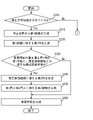
- FIG. 4 is a flowchart showing processing by the route setting program in one embodiment.
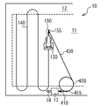
- FIG. 5 is a diagram for explaining the position of transition from the work route to the change route in one embodiment.
- FIG. 6 is a diagram for explaining a stop position and a stop direction in one embodiment.
- FIG. 7 is a flowchart showing a process of generating a change path in one embodiment.
- FIG. 8 is a diagram for explaining a process of generating a change route in one embodiment.
- FIG. 9 is a diagram for explaining a process of generating a change route in one embodiment.
- FIG. 1 is a schematic view of a field in one embodiment.
- FIG. 2 is a configuration diagram of an autonomous traveling system according to an embodiment.
- FIG. 3 is a functional block
- FIG. 10 is a diagram for explaining a process of generating a change path in one embodiment.
- FIG. 11 is a diagram for explaining a process of generating a change route in one embodiment.
- FIG. 12A is a flowchart showing a process of generating a change path in one embodiment.
- FIG. 12B is a flowchart showing a process of generating a change path in one embodiment.
- FIG. 13 is a diagram for explaining a process of generating a change route in one embodiment.
- FIG. 14 is a diagram for explaining a process of generating a change path in one embodiment.
- FIG. 15 is a diagram for explaining a process of generating a change route in one embodiment.
- FIG. 16 is a diagram for explaining a process of generating a change path in one embodiment.
- the field 10 in which the work, for example, plowing, leveling, fertilization, harvesting, etc., is performed using the work vehicle 130 surrounds the central work area 11 and the work area 11 as shown in FIG. It has a headland 12 and the like.
- the work area 11 represents an area where work is performed and crops are cultivated.
- the headland 12 is provided, for example, for the work vehicle 130 to turn.
- the work vehicle 130 automatically moves along a preset work path 140.
- the work vehicle 130 includes a vehicle that pulls the work machine, such as a tractor, and a vehicle that is integrally formed with the work machine, such as a combine.
- the work vehicle 130 moves in the field 10 along the work path 140 to perform work using the work machine in the field 10.
- the work vehicle 130 consumes materials mounted on the work machine, such as seedlings, fertilizers, pesticides, etc., to perform work in the field 10.
- materials mounted on the work machine such as seedlings, fertilizers, pesticides, etc.
- the work vehicle 130 deviates from the work path 140 and moves to a predetermined stop position 13 in order to replenish the materials.
- the work vehicle 130 stops at the stop position 13 so that the traveling direction faces a predetermined direction, for example, a direction in which materials can be easily replenished. Further, the work vehicle 130 may move without stopping when moving away from the work path 140. As a result, the worker can work efficiently.
- the work vehicle 130 works in the field 10 while storing the harvested crops.
- the work vehicle 130 deviates from the work path 140 and moves to a predetermined stop position 13 in order to discharge the crops. Also in this case, the worker can efficiently perform the work by stopping so that the traveling direction of the work vehicle 130 faces a predetermined direction.
- the autonomous traveling system 100 includes a terminal 110 and a work vehicle 130.
- the terminal 110 creates a route for the work vehicle 130 to move in the field.
- the terminal 110 includes, for example, a computer, a tablet, a mobile phone, and the like.
- the terminal 110 includes an input / output device 111, a communication device 112, a storage device 113, and an arithmetic unit 114.
- Information for the arithmetic unit 114 to execute the process is input to the input / output device 111.
- the input / output device 111 outputs the result of the processing executed by the arithmetic unit 114.
- the input / output device 111 includes various input devices and output devices, and includes, for example, a keyboard, a mouse, a microphone, a display, a speaker, a touch panel, and the like.
- the communication device 112 communicates with the communication device 131 of the work vehicle 130.
- the communication device 112 transfers each information acquired from the work vehicle 130 to the arithmetic unit 114. Further, the signal generated by the arithmetic unit 114 is transferred to the communication device 131 of the work vehicle 130.
- the communication device 112 includes various interfaces such as a wireless LAN (Local Area Network) transmitter / receiver, a NIC (Network Interface Card), and a USB (Universal Serial Bus).
- the storage device 113 stores various data for setting the route of the work vehicle 130, for example, the route setting program 200.
- the storage device 113 is used as a non-transitory tangible storage medium for storing the routing program 200.
- the route setting program 200 may be provided as a computer program product recorded on a computer-readable storage medium 1, or may be provided as a computer program product that can be downloaded from a server.
- the arithmetic unit 114 reads and executes the route setting program 200 from the storage device 113 to perform various data processing for setting the route of the work vehicle 130. By executing the route setting program 200, the arithmetic unit 114 realizes the work route setting unit 210, the status confirmation unit 220, the stop position setting unit 230, and the change route setting unit 240, as shown in FIG. do.
- the arithmetic unit 114 includes a central processing unit (CPU; Central Processing Unit) and the like.
- the work route setting unit 210 generates a work route 140 to which the work vehicle 130 moves when the work is performed in the field 10.
- the status confirmation unit 220 acquires the position of the work vehicle 130 in the field 10 at each time and confirms the work status in the field.
- the stop position setting unit 230 sets the stop position 13 at which the work vehicle 130 stops when replenishing materials or the like.
- the change route setting unit 240 generates a change route when the work vehicle 130 moves to the stop position 13.
- the work vehicle 130 includes a communication device 131, a positioning device 132, and a control device 133.
- the communication device 131 communicates with the communication device 112 of the terminal 110.
- the communication device 131 transfers each information acquired from the arithmetic unit 114 of the terminal 110 to the control device 133. Further, the signal generated by the control device 133 is transferred to the communication device 112 of the terminal 110.
- the communication device 131 includes various interfaces such as a wireless LAN (Local Area Network) transmitter / receiver, a NIC (Network Interface Card), and a USB (Universal Serial Bus).
- the positioning device 132 measures the position of the work vehicle 130.
- the positioning device 132 is, for example, a receiver of a GNSS (Global Navigation Satellite System), receives a signal from an artificial satellite or a base station on the ground, and measures the position of the work vehicle 130 at each time.
- the position information representing the measured time and position is transmitted to the control device 133.
- GNSS Global Navigation Satellite System
- the control device 133 controls each part of the work vehicle 130 to realize the vehicle control unit 260 shown in FIG.
- the vehicle control unit 260 acquires the position information of the work vehicle 130 from the positioning device 132, operates the work vehicle 130, for example, accelerates, steers, and brakes, and along the path of acquiring the work vehicle 130 from the terminal 110. Move it. Further, the vehicle control unit 260 controls the operation of the work vehicle 130 to perform the work in the field 10.
- the control device 133 includes an arithmetic unit such as a central processing unit (CPU).
- step S110 the work route setting unit 210 realized by the arithmetic unit 114 of the terminal 110 generates a work route 140 and a work start signal indicating the start of work in the vehicle control unit 260 of the work vehicle 130.
- the vehicle control unit 260 controls the work vehicle 130 so as to automatically move along the work path 140 represented by the work start signal. Further, the vehicle control unit 260 controls the operation of the work machine based on the work start signal.
- the work path 140 is set before starting the work and is stored in the storage device 113 of the terminal 110.
- the status confirmation unit 220 acquires position information from the vehicle control unit 260 of the work vehicle 130. Specifically, the vehicle control unit 260 transmits the position information measured by the positioning device 132 to the status confirmation unit 220. The status confirmation unit 220 acquires the position of the work vehicle 130 at each time from the acquired position information. Based on the acquired position of the work vehicle 130, the status confirmation unit 220 acquires the position of the work vehicle 130 in the work path 140. The situation confirmation unit 220 may acquire the state of the work vehicle 130, for example, the current position, the traveling direction, the speed, and the like, based on the acquired position of the work vehicle 130 at each time.
- step S130 the status confirmation unit 220 determines whether the route change operation for moving the work vehicle 130 to the stop position 13 has been input to the input / output device 111 of the terminal 110.
- the status confirmation unit 220 displays a route change button on the input / output device 111 of the terminal 110, and accepts a route change operation by the user.
- the status confirmation unit 220 determines that the route change operation has been input.
- the status confirmation unit 220 determines that the route change operation has not been input, the status confirmation unit 220 returns to the process of step S120 and repeats the process.
- the status confirmation unit 220 determines that the route change operation has been input, the process proceeds to step S140.
- step S140 the change route setting unit 240 determines the change start position 155 of the work vehicle 130 when changing from the work route 140 to the change route based on the current position of the work vehicle 130.
- the change route setting unit 240 acquires the delay time from the input of the route change operation to the change of the route of the work vehicle 130.
- the delay time is determined, for example, based on the processing time for generating the change path.
- the change route setting unit 240 determines the position of the work vehicle 130 after the time when the route change operation is input by the change waiting time representing the time equal to or longer than the acquired delay time. For example, as shown in FIG.
- the change route setting unit 240 calculates an assumed movement route 150 in which the work vehicle 130 moves along the work route 140 for a predetermined time.
- the change route setting unit 240 determines the end point of the assumed movement route 150 as the change start position 155. Further, the change route setting unit 240 may determine the assumed movement route 150 as a route in which the work vehicle 130 travels by a predetermined distance, for example, 1 m in the traveling direction. In this case, the predetermined distance is determined to be greater than the distance traveled by the work vehicle 130 during the delay time.
- the delay time may be stored in the storage device 113 in advance, or may be calculated based on a history of time required for each process, for example, a communication delay between the terminal 110 and the work vehicle 130.
- the stop position setting unit 230 selects the stop position 13 and the stop direction 14 indicating the traveling direction of the work vehicle 130 when the work vehicle 130 stops at the stop position 13, according to the input of the user. ..
- the user selects the stop position 13 on the map of the field 10 displayed on the input / output device 111 of the terminal 110.
- the stop position setting unit 230 sets the selected stop position 13 as the destination of the change route.
- the user selects the stop direction 14 indicating the traveling direction when the work vehicle 130 stops at the stop position 13.
- the stop position setting unit 230 sets the selected stop direction 14 as the traveling direction when the work vehicle 130 reaches the stop position 13.
- the stop position 13 and the stop direction 14 may be preset or may be selected from a plurality of combinations.
- step S160 shown in FIG. 4 the change route setting unit 240 generates a change route starting from the change start position 155 and ending at the stop position 13. The method of generating the change route will be described later.
- step S170 the change route setting unit 240 generates a change start signal indicating the change route in the vehicle control unit 260 of the work vehicle 130.
- the vehicle control unit 260 changes the route after the change start position 155 to the change route represented by the change start signal. Therefore, the vehicle control unit 260 controls the work vehicle 130 so as to move along the work path 140 to the change start position 155 and automatically move from the change start position 155 along the change path without stopping. do.
- the status confirmation unit 220 acquires position information from the vehicle control unit 260 of the work vehicle 130. Specifically, the vehicle control unit 260 transmits the position information measured by the positioning device 132 to the status confirmation unit 220. The status confirmation unit 220 acquires the position of the work vehicle 130 at each time from the acquired position information.
- step S180 the status confirmation unit 220 confirms that the work vehicle 130 has reached the stop position 13 and has stopped.
- the process ends.
- the arithmetic unit 114 generates a change path so as to face the set stop direction 14 and stop at the stop position 13.
- the vehicle control unit 260 moves the work vehicle 130 along the generated change route. In this way, according to the autonomous traveling method, the work vehicle 130 can move to the set stop position 13 so that the traveling direction is the set stop direction.
- the arithmetic unit 114 of the terminal 110 executes the process shown in FIG. 7 to generate a change route.
- the change route setting unit 240 realized by the arithmetic unit 114 of the terminal 110 generates the first route 410 based on the stop position 13 in step S210. Specifically, as shown in FIG. 8, the change route setting unit 240 sets a line segment extending by a predetermined distance, for example, 1 m in the direction opposite to the stop direction 14 as the first route 410 with the stop position 13 as the end point. do.
- the first path 410 indicates that the work vehicle 130 advances in the stop direction 14 along the set line segment.
- the change route setting unit 240 In step S220 shown in FIG. 7, the change route setting unit 240 generates a first circle 420 in contact with the first route 410, and generates a route for the work vehicle 130 to enter the first route 410.
- the change route setting unit 240 uses the first start point 415 of the first route 410 as a contact point and generates a first circle 420 in contact with the first route 410. More specifically, the first circle 420 is generated so as to tangent to a straight line including the first path 410.
- the work vehicle 130 changes the traveling direction to the right along the circumference of the first circle 420 and moves the circumference of the first circle 420 clockwise to make the first path. Move along the 410.
- the first circle 420 has a minimum turning radius that represents the minimum radius that the work vehicle 130 can turn.
- the change route setting unit 240 has a first tangent line 430 that passes through the change start position 155 and is in contact with the first circle 420, and an assumed movement route 150 until the work vehicle 130 moves to the change start position 155. It is determined whether the angle formed by is less than the threshold value. Specifically, as shown in FIG. 8, the change route setting unit 240 generates a first tangent line 430 that passes through the change start position 155 and is in contact with the first circle 420. Next, as shown in FIG. 9, the first angle 450 formed by the assumed movement path 150 and the first tangent line 430 is calculated.
- the change route setting unit 240 compares the calculated first angle 450 with the threshold value, and executes the process of step S240 when the first angle 450 is smaller than the threshold value. When the first angle 450 is equal to or greater than the threshold value, the change route setting unit 240 executes the process of step S260.
- the threshold value is determined based on an angle at which the turning radius can be ignored when the working vehicle 130 changes the traveling direction. For example, if the angle for changing the traveling direction of the work vehicle 130 is 45 degrees or less and the turning radius of the work vehicle 130 can be ignored, the threshold value is 135 degrees.
- step S240 the change route setting unit 240 generates a second circle 440 whose contact point is the end point of the assumed movement route 150 so that the work vehicle 130 turns toward the first circle 420.
- the change route setting unit 240 uses the change start position 155, which is the end point of the assumed movement route 150, as a contact point, and generates a second circle 440 in contact with the assumed movement route 150. More specifically, the second circle 440 is generated so as to be in contact with a straight line extending in the traveling direction of the work vehicle 130 at the end point of the assumed movement path 150.
- the work vehicle 130 changes the traveling direction to the right along the circumference of the second circle 440 and moves the circumference of the second circle 440 clockwise. The direction of travel is toward the first circle 420.
- the second circle 440 has a minimum turning radius that represents the minimum radius that the work vehicle 130 can turn.
- step S250 the change route setting unit 240 generates a second tangent line 460 that touches the first circle 420 and the second circle 440.
- the second tangent line 460 represents the route when the work vehicle 130 moves from the second circle 440 to the first circle 420.
- the circumference of the second circle 440 is a path for the work vehicle 130 to move clockwise. Therefore, the change route setting unit 240 generates the second tangent line 460 so that the second circle 440 is located to the right of the work vehicle 130 when the work vehicle 130 moves along the second tangent line 460.
- the circumference of the first circle 420 is also a path for the work vehicle 130 to move clockwise.
- the change route setting unit 240 generates the second tangent line 460 so that the first circle 420 is located to the right of the work vehicle 130 when the work vehicle 130 moves along the second tangent line 460.
- the second tangent line 460 is generated according to the direction in which the work vehicle 130 turns when moving on the circumference of the first circle 420 and on the circumference of the second circle 440.
- step S260 the change route setting unit 240 generates a change route that connects each of the generated circles and line segments.
- the change route setting unit 240 changes the route connecting the circumference of the second circle 440, the second tangent line 460, the circumference of the first circle 420, and the first route 410.
- the change path 500 is the change path 500.
- the change route setting unit 240 includes an arc set as the change path 500 in the circumference of the second circle 440, a line segment set as the change path 500 in the second tangent line 460, and the first circle.
- the process of generating the change path 500 is completed by generating the change path 500 connecting the arc set as the change path 500 and the first path 410 out of the circumference of the 420.
- step S230 When NO is determined in step S230, specifically, when the first angle 450 formed by the first tangent line 430 and the assumed movement path 150 is equal to or greater than the threshold value, the change route setting unit 240 uses the second circle 440. Does not generate. Therefore, the change route setting unit 240 generates, for example, the change route 500 connecting the generated first tangent line 430, the circumference of the first circle 420, and the first route 410.
- the autonomous traveling system 100 can control the work vehicle 130 so as to deviate from the work path 140 and move to a predetermined stop position 13. Further, the work vehicle 130 stops so that the traveling direction faces a predetermined direction. Further, the work vehicle 130 shifts from the work route 140 to the change route 500 without stopping. As described above, the autonomous traveling system 100 allows the operator to efficiently perform the work.
- the autonomous traveling system 100 may move the work vehicle 130 to the stop position 13 without setting the traveling direction of the work vehicle 130 at the stop position 13.
- the autonomous traveling system 100 may move the work vehicle 130 to the stop position 13 so that the time required to move to the stop position 13 is shortened.
- the worker can move the work vehicle 130 according to whether the traveling direction of the work vehicle 130 at the stop position 13 or the time required to move to the stop position 13 is prioritized. ..
- the autonomous traveling system 100 moves the work vehicle 130 to the stop position 13 by the shortest path. Since the configuration of the autonomous traveling system 100 is the same as that of the first embodiment, the description thereof will be omitted.
- the arithmetic unit 114 of the terminal 110 executes the processes shown in FIGS. 12A and 12B to generate the change path 500.
- the change route setting unit 240 realized by the arithmetic unit 114 of the terminal 110 determines in step S205 whether the stop direction 14 of the work vehicle 130 at the stop position 13 is set. When the stop direction 14 is set, the change route setting unit 240 executes the process of step S210. When the stop direction 14 is not set, the change route setting unit 240 executes the process of step S330 shown in FIG. 12B.
- step S210 to step S260 shown in FIG. 12A Since the processes from step S210 to step S260 shown in FIG. 12A are the same as those in the first embodiment, the description thereof will be omitted.
- step S330 shown in FIG. 12B the change route setting unit 240 forms a line segment connecting the change start position 155 and the stop position 13 and an assumed movement route 150 until the work vehicle 130 moves to the change start position 155. Determine if the angle is less than the threshold. Specifically, as shown in FIG. 13, the change route setting unit 240 generates a first line segment 630 connecting the change start position 155 and the stop position 13. Next, as shown in FIG. 14, the second angle 650 formed by the assumed movement path 150 and the first line segment 630 is calculated. The change route setting unit 240 compares the calculated second angle 650 with the threshold value, and executes the process of step S340 when the second angle 650 is smaller than the threshold value. When the second angle 650 is equal to or greater than the threshold value, the change route setting unit 240 executes the process of step S360.
- the threshold value is determined based on an angle at which the turning radius can be ignored when the working vehicle 130 changes the traveling direction.
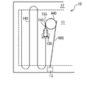
- step S340 shown in FIG. 12B the change route setting unit 240 generates a second circle 440 having the end point of the assumed movement route 150 as a contact point so that the work vehicle 130 turns toward the stop position 13.
- the change route setting unit 240 uses the change start position 155, which is the end point of the assumed movement route 150, as a contact point, and generates a second circle 440 in contact with the assumed movement route 150.
- the work vehicle 130 changes the traveling direction to the right along the circumference of the second circle 440 and moves the circumference of the second circle 440 clockwise. The direction of travel is directed to the stop position 13.
- the second circle 440 has a minimum turning radius that represents the minimum radius that the work vehicle 130 can turn.
- step S350 the change route setting unit 240 passes through the stop position 13 and generates a third tangent line 660 tangent to the second circle 440.
- the third tangent line 660 represents a route when the work vehicle 130 moves from the second circle 440 to the stop position 13.
- the circumference of the second circle 440 is a path for the work vehicle 130 to move clockwise. Therefore, the change route setting unit 240 generates the third tangent line 660 so that the second circle 440 is located to the right of the work vehicle 130 when the work vehicle 130 moves along the third tangent line 660.
- the third tangent line 660 is generated according to the direction in which the work vehicle 130 turns when moving on the circumference of the second circle 440.
- step S360 the change route setting unit 240 generates a change route 500 that connects each of the generated circles and line segments.
- the change route setting unit 240 changes the route connecting the circumference of the second circle 440, the second tangent line 460, the circumference of the first circle 420, and the first route 410.
- the change path 500 is the change path 500.
- a line segment whose starting point is the contact point with the second circle 440 and whose end point is the stop position 13 is set as a part of the change path 500.
- the change route setting unit 240 connects the arc set as the change path 500 in the circumference of the second circle 440 and the line segment set as the change path 500 in the third tangent line 660. It is generated as the change path 500, and the process of generating the change path 500 is terminated.
- step S330 When NO is determined in step S330, specifically, when the second angle 650 formed by the third tangent line 660 and the assumed movement path 150 is equal to or greater than the threshold value, the change route setting unit 240 uses the second circle 440. Does not generate. Therefore, the change route setting unit 240 generates, for example, the first line segment 630 connecting the generated change start position 155 and the stop position 13 as the change route 500.
- the autonomous traveling system 100 can move the work vehicle 130 so that the time required to move to the stop position 13 is shortened by not setting the stop direction 14. Therefore, the worker can select the change route 500 according to the situation.
- the change route setting unit 240 may generate the shortest route as the change route 500, which minimizes the distance traveled from the change start position 155 to the stop position 13.
- the configuration described in the embodiment is an example, and the configuration can be changed as long as the function is not impaired.
- the situation confirmation unit 220 has shown an example of moving the work vehicle 130 to the stop position 13 based on the input of the route change operation, but the present invention is not limited to this.
- the situation confirmation unit 220 may move the work vehicle 130 to the stop position 13 based on a predetermined instruction.
- the situation confirmation unit 220 may move the work vehicle 130 according to a supply instruction indicating that materials mounted on the work vehicle 130, such as seedlings, fertilizers, and pesticides, are to be replenished.
- the status confirmation unit 220 acquires the amount of materials loaded from the work vehicle 130.
- the status confirmation unit 220 determines that a replenishment instruction for replenishing the material has been input. Further, by inputting an operation for replenishing the material by the user, the status confirmation unit 220 may determine that the replenishment instruction has been input.
- the situation confirmation unit 220 may move the work vehicle 130 to the stop position 13 based on the discharge instruction indicating that the harvested crop is discharged. For example, the status confirmation unit 220 acquires the amount of crops stored from the work vehicle 130. When the amount of the acquired crop is larger than the threshold value, the status confirmation unit 220 determines that the discharge instruction for discharging the crop has been input. Further, the status confirmation unit 220 may determine that the discharge instruction has been input by inputting the operation for replenishing the material by the user.
- the status confirmation unit 220 may move the work vehicle 130 to the stop position 13 set outside the work area 11 based on the evacuation instruction indicating to evacuate from the work area 11. For example, the status confirmation unit 220 accepts an evacuation operation for retracting the work vehicle 130 to the stop position 13 from the user. When the status confirmation unit 220 accepts the evacuation operation, it determines that the evacuation instruction has been input. When the evacuation instruction is input, the change route setting unit 240 generates the change route 500 for moving the work vehicle 130 to the stop position 13.
- the change route setting unit 240 may change the change route 500 when the change route 500 passes through a travel prohibited area, for example, the outside of the field 10 when the change route 500 is generated.
- the change route setting unit 240 sets the change route 500 so that when the change route 500 passes through the travel prohibited area, the work vehicle 130 moves along the boundary of the travel prohibited area, for example, the boundary between the field 10 and the outside.
- the change route setting unit 240 extracts a position where the work vehicle 130 enters the prohibited area when the work vehicle 130 moves along the generated change route 500, for example, a position where the work vehicle exits the field 10 as a starting point. do.
- the change route setting unit 240 extracts a position where the work vehicle 130 moves out of the prohibited area when the work vehicle 130 moves along the generated change route 500, for example, a position where the work vehicle enters the inside from the outside of the field 10 as an end point. ..
- the change route setting unit 240 generates a detour route connecting the extracted start point to the end point along the outer periphery of the traveling prohibited area, for example, the boundary between the field 10 and the outside.
- the change route setting unit 240 changes the route included in the travel prohibited area among the change routes 500 to the generated detour route. As a result, the change route 500 that does not pass through the traveling prohibited area is generated.
- the travel prohibited area represents, for example, the outside of the field 10, and may be changed by the user.
- the positioning device 132 may be arbitrarily selected as long as it can measure the position of the work vehicle 130.
- the positioning device 132 may measure the position of the work vehicle 130 by acquiring the speed, the traveling direction, and the like of the work vehicle 130 and calculating the movement route of the work vehicle 130.
- the change route setting unit 240 may determine whether to prioritize the stop direction 14 or the time required to move to the stop position 13. For example, the status confirmation unit 220 accepts which of the stop direction 14 and the time required to move to the stop position 13 is prioritized.
- the user inputs whether to prioritize the stop direction 14 or the time required to move to the stop position 13.
- the change route setting unit 240 shifts to the process of step S210.
- the time priority instruction indicating that the time required to move to the stop position 13 is prioritized is input, the change route setting unit 240 shifts to the process of step S330.
- the stop position 13 is not limited to this, and may be set outside the field 10, for example, in another adjacent field.
- the change route setting unit 240 generates a change route 500 for the work vehicle 130 to move from the field 10 to another adjacent field.
- the vehicle control unit 260 moves the work vehicle 130 from the field 10 to another adjacent field by moving the work vehicle 130 along the generated change path 500.
- the terminal 110 may be realized by a plurality of terminals 110, and the terminal 110 may be a route setting device including a status confirmation unit 220 and a change route setting unit 240. Further, the terminal 110 may be an autonomous traveling system including a vehicle control unit 260.
- the change route setting unit 240 may perform only a part of the processing.
- the autonomous travel system 100 may control the work vehicle 130 so that it stops when the work vehicle 130 changes from the work route 140 to the change route 500.
- the change route setting unit 240 processes the change start position 155 of the work vehicle 130 when the route is changed as the current position of the work vehicle 130.
- the autonomous traveling system 100 does not have to control the traveling direction of the work vehicle 130 at the stop position 13 by omitting the process of setting the stop direction 14.
Landscapes
- Engineering & Computer Science (AREA)
- Life Sciences & Earth Sciences (AREA)
- Physics & Mathematics (AREA)
- Automation & Control Theory (AREA)
- General Physics & Mathematics (AREA)
- Aviation & Aerospace Engineering (AREA)
- Radar, Positioning & Navigation (AREA)
- Remote Sensing (AREA)
- Environmental Sciences (AREA)
- Soil Sciences (AREA)
- Mechanical Engineering (AREA)
- Business, Economics & Management (AREA)
- Health & Medical Sciences (AREA)
- Artificial Intelligence (AREA)
- Evolutionary Computation (AREA)
- Game Theory and Decision Science (AREA)
- Medical Informatics (AREA)
- Control Of Position, Course, Altitude, Or Attitude Of Moving Bodies (AREA)
- Guiding Agricultural Machines (AREA)
Abstract
Priority Applications (4)
| Application Number | Priority Date | Filing Date | Title |
|---|---|---|---|
| CN202180083152.0A CN116583806A (zh) | 2020-12-22 | 2021-12-03 | 路径设定方法、自主行驶方法、路径设定装置、自主行驶系统以及存储介质 |
| KR1020237020514A KR20230123957A (ko) | 2020-12-22 | 2021-12-03 | 경로 설정 방법, 자율 주행 방법, 경로 설정 장치, 자율 주행 시스템, 및 기억 매체 |
| EP21910222.5A EP4268553A4 (fr) | 2020-12-22 | 2021-12-03 | Procédé de réglage d'itinéraire, procédé de déplacement autonome, dispositif d'établissement d'itinéraire, système de déplacement autonome et support de stockage |
| US18/268,965 US12560928B2 (en) | 2020-12-22 | 2021-12-03 | Route change systems and methods for stopping autonomous travel at a modified stop position |
Applications Claiming Priority (2)
| Application Number | Priority Date | Filing Date | Title |
|---|---|---|---|
| JP2020-212146 | 2020-12-22 | ||
| JP2020212146A JP7453902B2 (ja) | 2020-12-22 | 2020-12-22 | 経路設定方法、自律走行方法、経路設定装置、自律走行システム、及び経路設定プログラム |
Publications (1)
| Publication Number | Publication Date |
|---|---|
| WO2022138070A1 true WO2022138070A1 (fr) | 2022-06-30 |
Family
ID=82159557
Family Applications (1)
| Application Number | Title | Priority Date | Filing Date |
|---|---|---|---|
| PCT/JP2021/044461 Ceased WO2022138070A1 (fr) | 2020-12-22 | 2021-12-03 | Procédé de réglage d'itinéraire, procédé de déplacement autonome, dispositif d'établissement d'itinéraire, système de déplacement autonome et support de stockage |
Country Status (6)
| Country | Link |
|---|---|
| US (1) | US12560928B2 (fr) |
| EP (1) | EP4268553A4 (fr) |
| JP (2) | JP7453902B2 (fr) |
| KR (1) | KR20230123957A (fr) |
| CN (1) | CN116583806A (fr) |
| WO (1) | WO2022138070A1 (fr) |
Families Citing this family (3)
| Publication number | Priority date | Publication date | Assignee | Title |
|---|---|---|---|---|
| JP7511491B2 (ja) * | 2021-01-05 | 2024-07-05 | 株式会社クボタ | 自動走行システム及び自動走行方法 |
| EP4476598A2 (fr) * | 2022-02-07 | 2024-12-18 | Doosan Bobcat North America, Inc. | Détermination de trajet pour tondeuses automatiques |
| US12353209B2 (en) * | 2023-01-04 | 2025-07-08 | Kubota Corporation | Agricultural support system, and device and method to generate travel route for hailed agricultural machine |
Citations (8)
| Publication number | Priority date | Publication date | Assignee | Title |
|---|---|---|---|---|
| JPH09154315A (ja) | 1995-12-12 | 1997-06-17 | Kubota Corp | 作業車の制御装置 |
| JP2000172337A (ja) * | 1998-12-07 | 2000-06-23 | Mitsubishi Electric Corp | 自律移動ロボット |
| JP2015112071A (ja) * | 2013-12-12 | 2015-06-22 | 株式会社クボタ | 圃場作業機 |
| US20150319913A1 (en) * | 2014-05-11 | 2015-11-12 | Cnh Industrial America Llc | Mission control system and method for an agricultural system |
| JP2018050491A (ja) * | 2016-09-26 | 2018-04-05 | ヤンマー株式会社 | 経路生成システム |
| JP2019174890A (ja) | 2018-03-27 | 2019-10-10 | ヤンマー株式会社 | 自動走行システム |
| JP2020039273A (ja) * | 2018-09-07 | 2020-03-19 | 株式会社クボタ | 収穫機 |
| JP2020135793A (ja) * | 2019-02-26 | 2020-08-31 | ヤンマーパワーテクノロジー株式会社 | 自動走行システム |
Family Cites Families (10)
| Publication number | Priority date | Publication date | Assignee | Title |
|---|---|---|---|---|
| KR102586010B1 (ko) * | 2014-02-28 | 2023-10-11 | 삼성전자주식회사 | 청소 로봇 및 그에 포함되는 원격 제어기 |
| US9711851B1 (en) * | 2016-02-04 | 2017-07-18 | Proxy Technologies, Inc. | Unmanned vehicle, system and method for transmitting signals |
| US11726485B2 (en) * | 2016-09-05 | 2023-08-15 | Kubota Corporation | Autonomous work vehicle travel system, travel route managing device, travel route generating device, and travel route determining device |
| KR102586896B1 (ko) * | 2016-12-02 | 2023-10-11 | 가부시끼 가이샤 구보다 | 주행 경로 관리 시스템 및 주행 경로 결정 장치 |
| JP6689738B2 (ja) | 2016-12-19 | 2020-04-28 | 株式会社クボタ | 作業車自動走行システム |
| JP6663382B2 (ja) * | 2017-03-24 | 2020-03-11 | ヤンマー株式会社 | 作業車両 |
| JP7142433B2 (ja) | 2017-12-21 | 2022-09-27 | 株式会社クボタ | 収穫機制御システム |
| CN112912693B (zh) * | 2018-10-22 | 2024-03-19 | 株式会社尼罗沃克 | 行驶路径生成系统、行驶路径生成方法和计算机可读取记录介质以及无人机 |
| US11520332B1 (en) * | 2019-12-03 | 2022-12-06 | Amazon Technologies, Inc. | System for automated exploration by an autonomous mobile device using markers based on image features |
| US11747152B2 (en) * | 2020-08-04 | 2023-09-05 | Verizon Connect Development Limited | Systems and methods for determining an optimized path for navigation based on features associated with points of interest |
-
2020
- 2020-12-22 JP JP2020212146A patent/JP7453902B2/ja active Active
-
2021
- 2021-12-03 CN CN202180083152.0A patent/CN116583806A/zh active Pending
- 2021-12-03 KR KR1020237020514A patent/KR20230123957A/ko active Pending
- 2021-12-03 WO PCT/JP2021/044461 patent/WO2022138070A1/fr not_active Ceased
- 2021-12-03 EP EP21910222.5A patent/EP4268553A4/fr active Pending
- 2021-12-03 US US18/268,965 patent/US12560928B2/en active Active
-
2024
- 2024-03-08 JP JP2024035542A patent/JP7682324B2/ja active Active
Patent Citations (8)
| Publication number | Priority date | Publication date | Assignee | Title |
|---|---|---|---|---|
| JPH09154315A (ja) | 1995-12-12 | 1997-06-17 | Kubota Corp | 作業車の制御装置 |
| JP2000172337A (ja) * | 1998-12-07 | 2000-06-23 | Mitsubishi Electric Corp | 自律移動ロボット |
| JP2015112071A (ja) * | 2013-12-12 | 2015-06-22 | 株式会社クボタ | 圃場作業機 |
| US20150319913A1 (en) * | 2014-05-11 | 2015-11-12 | Cnh Industrial America Llc | Mission control system and method for an agricultural system |
| JP2018050491A (ja) * | 2016-09-26 | 2018-04-05 | ヤンマー株式会社 | 経路生成システム |
| JP2019174890A (ja) | 2018-03-27 | 2019-10-10 | ヤンマー株式会社 | 自動走行システム |
| JP2020039273A (ja) * | 2018-09-07 | 2020-03-19 | 株式会社クボタ | 収穫機 |
| JP2020135793A (ja) * | 2019-02-26 | 2020-08-31 | ヤンマーパワーテクノロジー株式会社 | 自動走行システム |
Non-Patent Citations (1)
| Title |
|---|
| See also references of EP4268553A4 |
Also Published As
| Publication number | Publication date |
|---|---|
| CN116583806A (zh) | 2023-08-11 |
| US12560928B2 (en) | 2026-02-24 |
| KR20230123957A (ko) | 2023-08-24 |
| EP4268553A1 (fr) | 2023-11-01 |
| EP4268553A4 (fr) | 2025-01-15 |
| JP7682324B2 (ja) | 2025-05-23 |
| US20240045430A1 (en) | 2024-02-08 |
| JP2024072844A (ja) | 2024-05-28 |
| JP7453902B2 (ja) | 2024-03-21 |
| JP2022098639A (ja) | 2022-07-04 |
Similar Documents
| Publication | Publication Date | Title |
|---|---|---|
| JP7682324B2 (ja) | 自律走行システム、及び自律走行方法 | |
| EP3826896B1 (fr) | Appareil de commande de conduite de véhicule et procédé d'étalonnage réalisé par l'appareil de commande de conduite de véhicule | |
| US10598505B2 (en) | Travel route generation apparatus and method for generating travel route | |
| KR101879247B1 (ko) | 자율주행 농업기계의 작업경로 설정방법 | |
| CN107589740B (zh) | 路径搜索程序、路径搜索系统和作业车 | |
| JP6887256B2 (ja) | 走行経路生成装置 | |
| WO2019167199A1 (fr) | Dispositif de commande, corps mobile et programme | |
| CN106660629A (zh) | 遥控装置 | |
| JP2020022375A (ja) | 外形形状算出システム及び外形形状算出方法 | |
| JPWO2023119871A5 (fr) | ||
| US12560934B2 (en) | Route setting method, autonomous traveling method, route setting device, autonomous traveling system, and storage medium | |
| JP2020018220A (ja) | 作業管理システム及び作業管理方法 | |
| US12314059B2 (en) | Work machine and information management apparatus | |
| WO2021187384A1 (fr) | Dispositif de génération de piste de déplacement et procédé de génération de piste de déplacement | |
| JP7224151B2 (ja) | 走行経路生成システム及び走行経路生成方法 | |
| US20250249989A1 (en) | Navigation assist system, navigation assist method, and program | |
| US12342742B2 (en) | Automatic travel system and automatic travel method | |
| JP2024004592A (ja) | 作業評価方法、作業評価システムおよび作業評価プログラム | |
| US20220142045A1 (en) | Work machine and information management apparatus | |
| JP7061947B2 (ja) | ナビゲーション方法及びナビゲーション装置 | |
| JP7657675B2 (ja) | データ管理方法、データ管理システム、及びデータ管理プログラム | |
| JP6544984B2 (ja) | ネットワークシステム、サーバ、通信端末、および位置表示方法 | |
| US12596366B2 (en) | Work area management method, work area management system, and work area management program | |
| JP7579839B2 (ja) | 運転支援方法、処理装置、及び移動機 | |
| JP2003247845A (ja) | 経路送信方法、センターおよび経路案内装置 |
Legal Events
| Date | Code | Title | Description |
|---|---|---|---|
| 121 | Ep: the epo has been informed by wipo that ep was designated in this application |
Ref document number: 21910222 Country of ref document: EP Kind code of ref document: A1 |
|
| WWE | Wipo information: entry into national phase |
Ref document number: 202180083152.0 Country of ref document: CN |
|
| WWE | Wipo information: entry into national phase |
Ref document number: 18268965 Country of ref document: US |
|
| NENP | Non-entry into the national phase |
Ref country code: DE |
|
| ENP | Entry into the national phase |
Ref document number: 2021910222 Country of ref document: EP Effective date: 20230724 |
|
| WWG | Wipo information: grant in national office |
Ref document number: 18268965 Country of ref document: US |