WO2022138301A1 - 車両のハンドル装置 - Google Patents
車両のハンドル装置 Download PDFInfo
- Publication number
- WO2022138301A1 WO2022138301A1 PCT/JP2021/045910 JP2021045910W WO2022138301A1 WO 2022138301 A1 WO2022138301 A1 WO 2022138301A1 JP 2021045910 W JP2021045910 W JP 2021045910W WO 2022138301 A1 WO2022138301 A1 WO 2022138301A1
- Authority
- WO
- WIPO (PCT)
- Prior art keywords
- adjuster
- handle
- handle body
- link
- steering wheel
- Prior art date
- Legal status (The legal status is an assumption and is not a legal conclusion. Google has not performed a legal analysis and makes no representation as to the accuracy of the status listed.)
- Ceased
Links
Images







Classifications
-
- E—FIXED CONSTRUCTIONS
- E05—LOCKS; KEYS; WINDOW OR DOOR FITTINGS; SAFES
- E05B—LOCKS; ACCESSORIES THEREFOR; HANDCUFFS
- E05B85/00—Details of vehicle locks not provided for in groups E05B77/00 - E05B83/00
- E05B85/10—Handles
- E05B85/107—Pop-out handles, e.g. sliding outwardly before rotation
-
- E—FIXED CONSTRUCTIONS
- E05—LOCKS; KEYS; WINDOW OR DOOR FITTINGS; SAFES
- E05B—LOCKS; ACCESSORIES THEREFOR; HANDCUFFS
- E05B79/00—Mounting or connecting vehicle locks or parts thereof
- E05B79/02—Mounting of vehicle locks or parts thereof
- E05B79/06—Mounting of handles, e.g. to the wing or to the lock
-
- E—FIXED CONSTRUCTIONS
- E05—LOCKS; KEYS; WINDOW OR DOOR FITTINGS; SAFES
- E05B—LOCKS; ACCESSORIES THEREFOR; HANDCUFFS
- E05B81/00—Power-actuated vehicle locks
- E05B81/24—Power-actuated vehicle locks characterised by constructional features of the actuator or the power transmission
- E05B81/32—Details of the actuator transmission
- E05B81/42—Cams
-
- E—FIXED CONSTRUCTIONS
- E05—LOCKS; KEYS; WINDOW OR DOOR FITTINGS; SAFES
- E05B—LOCKS; ACCESSORIES THEREFOR; HANDCUFFS
- E05B85/00—Details of vehicle locks not provided for in groups E05B77/00 - E05B83/00
- E05B85/10—Handles
- E05B85/103—Handles creating a completely closed wing surface
-
- E—FIXED CONSTRUCTIONS
- E05—LOCKS; KEYS; WINDOW OR DOOR FITTINGS; SAFES
- E05B—LOCKS; ACCESSORIES THEREFOR; HANDCUFFS
- E05B63/00—Locks or fastenings with special structural characteristics
- E05B63/0056—Locks with adjustable or exchangeable lock parts
-
- E—FIXED CONSTRUCTIONS
- E05—LOCKS; KEYS; WINDOW OR DOOR FITTINGS; SAFES
- E05B—LOCKS; ACCESSORIES THEREFOR; HANDCUFFS
- E05B77/00—Vehicle locks characterised by special functions or purposes
- E05B77/36—Noise prevention; Anti-rattling means
- E05B77/38—Cushion elements, elastic guiding elements or holding elements, e.g. for cushioning or damping the impact of the bolt against the striker during closing of the wing
-
- E—FIXED CONSTRUCTIONS
- E05—LOCKS; KEYS; WINDOW OR DOOR FITTINGS; SAFES
- E05B—LOCKS; ACCESSORIES THEREFOR; HANDCUFFS
- E05B81/00—Power-actuated vehicle locks
- E05B81/02—Power-actuated vehicle locks characterised by the type of actuators used
- E05B81/04—Electrical
- E05B81/06—Electrical using rotary motors
-
- E—FIXED CONSTRUCTIONS
- E05—LOCKS; KEYS; WINDOW OR DOOR FITTINGS; SAFES
- E05B—LOCKS; ACCESSORIES THEREFOR; HANDCUFFS
- E05B85/00—Details of vehicle locks not provided for in groups E05B77/00 - E05B83/00
- E05B85/10—Handles
- E05B85/14—Handles pivoted about an axis parallel to the wing
- E05B85/16—Handles pivoted about an axis parallel to the wing a longitudinal grip part being pivoted at one end about an axis perpendicular to the longitudinal axis of the grip part
Definitions
- This disclosure relates to a vehicle steering wheel device.
- Patent Document 1 discloses a handle device having a handle body that can be pulled out from an initial position when a door is operated.
- the handle device has a handle portion (handle body) rotatably connected to one end of an operating lever driven by an electric motor (electric actuator) fixed on the handle base, and an operating lever of the handle body. It has an unlocking lever connected to the end connected to and the opposite end, and a guide portion formed at one end of the handle body and one end of the unlocking lever slides on a guide with a slot formed on the handle base. It is fitted flexibly.
- the handle body moves from the initial position located on the same surface as the door panel to the operating position raised from the door panel, and when the handle body is operated at the operating position, the door latch device can be released.
- the initial position is uniquely determined by the dimensional relationship between the parts, and if there is a dimensional error between the parts, the handle body may not be held on the same surface as the door panel. There is.
- the present disclosure relates to a vehicle steering wheel device that can adjust the positional relationship between the steering wheel body and the door panel surface to a predetermined position even if there is an error between parts.
- the steering wheel device of a vehicle has a steering wheel base configured to be fixed to the vehicle and a steering wheel body configured to be connected to the steering wheel base and retractable from an initial position.
- An adjustment portion is provided on the handle base.
- the adjusting unit is configured to be exposed to the outside when the handle body is pulled out from the initial position and can be operated, and to adjust the position of the handle body at the initial position.
- FIG. 1 is a front view showing a door handle device.
- FIG. 2 is a cross-sectional view taken along the line 2A-2A of FIG.
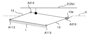
- FIG. 3A is a skeleton diagram of the door handle device, showing an initial state of the handle body.
- FIG. 3B is a skeleton diagram of the door handle device, showing the pop-up position of the handle body.
- FIG. 3C is a skeleton diagram of the door handle device, showing the operating position of the handle body.
- FIG. 4A is a diagram showing an adjustment state by the adjustment unit before adjustment.
- FIG. 4B is a diagram showing an adjustment state by the adjustment unit after adjustment.
- 5A is a cross-sectional view taken along the line 5A-5A of FIG. 4A.
- FIG. 5B is a cross-sectional view taken along the line 5B-5B of FIG. 4B.
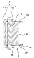
- FIG. 6A is a front view of the adjusting unit.
- FIG. 6B is a sectional view taken along line 6B-6B of FIG. 6A.
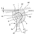
- FIG. 6C is a sectional view taken along line 6C-6C of FIG. 6A.
- FIG. 6D is a cross-sectional view taken along the line 6C-6C of FIG. 6A showing the adjusted state. It is a perspective view which shows the state which pulled out the handle body to a pop-up position, and exposed the adjustment part.
- the door handle device has a handle base 1, a handle body 2, and first and second links 12 and 13 connecting the handle body 2 to the handle base 1.
- the handle base 1 is fixed to the door of the vehicle.
- a handle portion 2a which serves as a handle when operating the door, is formed in the central portion of the handle body 2 in the longitudinal direction.
- the handle body 2 is configured to be movable between the initial position, the pop-up position, and the latch operation position described below.
- the surface 2b of the handle body 2 becomes substantially the same surface as the door panel (door surface 5) as shown in FIGS. 2 and 3A.
- the handle portion 2a is housed in the door.
- the handle body 2 When the handle body 2 is located at the pop-up position (FIG. 3B), the handle 2a pops out from the door panel, and the handle body 2 can be operated by putting a hand on the handle 2a.
- the handle body 2 is located at the latch operation position, as shown in FIG. 3C, the handle body 2 is in a state where one end of the handle body 2 is pulled up from the pop-up position.
- the driven portion 12a is pressed against the cam member 14 that is rotationally driven by a motor (not shown), and the first link 12 is rotationally driven around the connecting shaft A112 to the handle base 1.
- the first link 12 is provided with a clockwise rotational moment M12 by the torsion spring 15 in order to maintain the pressure contact state between the driven portion 12a and the cam member 14.
- the end opposite to the end of the first link 12 connected to the handle base 1 is rotatably connected to one end of the handle body 2 around the connecting shaft A212.
- one end of the second link 13 is rotatably connected to the handle base 1 around the connecting shaft A113.
- An elongated hole 13a is formed at the opposite end of the second link 13, and a connecting shaft A213 fixed to the other end of the handle body 2 is inserted so as to be idle and slidable.
- each component of the handle device has the handle base 1 as a fixed link, and is connected to the fixed link at intervals between the connecting shafts A112 and A113, respectively, in a kinematic pair.
- Two links 12, 13 and a slider slot 13a that is connected to the second link 13 by sliding kinematic pair, and a five-section link whose elements are the handle body 2 whose both ends rotate around the first link 12 and the slider 13a and are connected by kinematic pair. It constitutes a mechanism.
- the end of the sliding stroke of the slider 13a sliding on the second link 13 is predetermined as the end position of the elongated hole 13a, and in addition to the rotational moment M12 applied to the first link 12 described above, the second By applying the clockwise rotation moment M113 in FIG. 3A to the two links 13 by the torsion spring 16, the slider 13a is held at the stroke end position on the connecting shaft A113 side with the handle base 1 of the second link 13.
- the link lengths of the fixed link and the handle body 2 are the same, and the distance between the slider 13a at the stalk end position and the connecting axis A113 of the fixed link of the second link 13 (distance between A113 and A213 in FIG. 3A). Is formed so as to be equal to the link length of the first link 12, so that when the first link 12 is used as a drive link for electric rotation operation, it substantially operates as a four-node parallel link.
- the handle base 1 is provided with a latch operation mechanism (not shown) that is operated by the rotation of the connecting shaft A113 with the handle base 1 of the second link 13 from FIG. 3B to FIG. 3C, and the handle body 2 is operated. With rotation to the position, the latch operating mechanism releases the door latch device fixed to the door via an appropriate transmission means such as a cable device.
- a latch operation mechanism (not shown) that is operated by the rotation of the connecting shaft A113 with the handle base 1 of the second link 13 from FIG. 3B to FIG. 3C, and the handle body 2 is operated.
- the latch operating mechanism releases the door latch device fixed to the door via an appropriate transmission means such as a cable device.
- the handle base 1 is provided with an adjustment unit 3.
- the adjusting unit 3 includes a holding unit 7 and an adjuster 4 rotatably held by the holding unit 7.
- the holding portion 7 has a width direction dimension substantially equal to the width direction dimension of the handle portion 2a of the handle main body 2, and has a columnar head 8 and a connecting portion 9 protruding from the peripheral wall of the columnar head 8.
- a stopper wall 9a is provided at the protruding base end of the connecting portion 9 from the columnar head 8, and an elastic leg 9b is provided at the end of the stopper wall 9a.
- the elastic legs 9b are projected from both ends in the width direction of the stopper wall 9a, and the holding portion 7 opens a locking claw 9c formed at the tip of the elastic legs 9b on the handle base 1 as shown in FIGS. 5A and 5B. It is fixed to the handle base 1 by elastically locking the locking opening 1a.
- the connecting portion 9 extends from the columnar head 8 toward the center of the vehicle width, or extends along the thickness direction of the door, and the columnar head extends.
- the portion 8 is fixed in a posture located on the outermost side in the vehicle width direction.
- the regulator 4 is formed of a material having good impact absorption ability such as rubber and a flexible synthetic resin material. As shown in FIG. 6B, the adjuster 4 is formed by projecting a mounting piece 4b extending from both side walls of the link receiving portion 4a along the side wall portion of the holding portion 7, and the columnar head 8 is formed. The mounting shaft 6 fixed on the central shaft of the above is inserted through the mounting piece 4b and connected to the holding portion 7.
- the back surface (inner peripheral surface) of the link receiving portion 4a is in contact with and supported by the front surface of the cylindrical head 8 of the holding portion 7, and the link receiving portion 4a is supported by the cylindrical head. 8 can be covered, and the back surface of the link receiving portion 4a can rotate around the mounting shaft 6 while sliding on the surface of the columnar head 8.
- the regulator 4 is formed with a stopper 4c that abuts on the stopper wall 9a of the holding portion 7 to regulate the rotation angle.
- a protrusion-shaped convex portion 10 for clicking is provided on the back surface of the link receiving portion 4a of the adjuster 4, and a groove-shaped concave portion 11 for clicking is provided on the peripheral wall of the columnar head 8 of the holding portion 7, respectively. And is formed over the entire length of the holding portion 7 in the width direction.
- the moderation stop position (rotation stop position) is set at two positions (the initial rotation position shown in FIG. 6C and the adjustment rotation position shown in FIG. 6D) at the rotation end position where the stopper 4c abuts on the stopper wall 9a.
- the outer peripheral wall of the link receiving portion 4a has a cam shape in which the distance from the mounting shaft 6 differs depending on the rotation angle.
- the adjuster 4 is formed in a cam shape in which the distance between the center of rotation of the adjuster 4 (mounting shaft 6) and the surface of the outer peripheral wall of the adjuster 4 is different over the circumferential direction of the adjuster 4. ..
- contact surfaces 4d are formed at two locations corresponding to the two moderation stop positions. The contact surface 4d is formed by an inclined surface configured to abut on the ridgeline on the back surface of the handle portion 2a.
- the distance of the contact surface 4d from the mounting shaft 6 is when the surface of the handle body 2 is deviated from a predetermined position, for example, a position flush with the surface of the door panel 5 while the handle body 2 is in the initial position. To be precise, it is set so that the handle body 2 can be pushed out to a predetermined position when it is in a position subducted from the surface of the door panel 5.
- the adjuster 4 also serves as a bumper at the initial position of the handle body 2 at the time of initial setting, and the contact surface 4d abuts on the back surface of the handle portion 2a of the handle body 2 at the time of the initial setting. Is formed like this.
- the handle device is fixed to the door in the initial setting state, and as shown in FIGS. 4A and 5A, when the surface of the handle body 2 is in a state of being subducted with respect to the surface of the door panel 5, adjustment is made.
- the adjuster 4 of the unit 3 is rotated from the initial rotation position to the adjustment rotation position.
- the contact surface 4d of the adjuster 4 is formed by an inclined surface having the same inclination angle as the inclination angle of the back surface ridge line of the handle portion 2a of the handle body 2 with respect to a predetermined horizontal plane, and is shown in FIG. 6C.
- the contact surface 4d moves from the position shown by the solid line in FIG. 6C to the position shown by the chain line.
- the chain line in FIG. 6D indicates the position of the contact surface at the initial rotation position.
- the steering wheel main body 2 is extruded by a distance ( ⁇ ) in the vehicle width direction, and as shown in FIGS. 4B and 5B, when the steering wheel main body 2 is located at the initial position, the surface of the steering wheel main body 2 is the door panel 5. Match the surface.
- the adjuster 4 of the adjusting unit 3 is hidden behind the handle body 2 and is not exposed to the outside when the handle body 2 is in the initial position, but the handle body 2 is in the pop-up position. When moved to, as shown in FIG. 7, it is exposed to the outside and can be operated.
- the adjuster 4 can be operated from the initial rotation position to the adjustment rotation position by temporarily moving the handle body 2 to the pop-up position, whereby the initial position of the handle body 2 can be operated.
- the positional relationship with the door panel 5 in the above can be adjusted.
- the initial rotation position and the position are determined.
- the relative relationship of most of the handle devices with the door panel 5 can be kept within the settable value of the handle device of the vehicle according to the embodiment of the present disclosure. It is also possible to make fine adjustments by setting the fourth rotational moderation position and making the position of each contact surface different.
- the steering wheel device of the vehicle includes a steering wheel base 1 configured to be fixed to the vehicle, a steering wheel body 2 connected to the steering wheel base 1 and configured to be retractable from an initial position.
- the handle base 1 is provided with an adjusting portion 3.
- the adjusting unit 3 When the handle body 2 is pulled out from the initial position, the adjusting unit 3 is exposed to the outside and can be operated, and is configured to adjust the position of the handle body 2 at the initial position.
- the surface of the handle body 2 needs to occupy a predetermined relative position with respect to the door surface 5 due to design requirements and the like.
- the relative position of the handle body 2 at the initial position with respect to the door surface 5 can be adjusted by operating the adjusting unit 3.
- the handle body 2 is adjusted to a predetermined position. Can be done.
- the adjustment unit 3 is exposed to the outside in a state where the handle body 2 is moved from the initial position, the adjustment operation of the adjustment unit 3 is possible. Therefore, the position of the handle body 2 can be adjusted while the handle device is fixed to the door. As a result, the adjustment workability is improved.
- the adjusting unit 3 is exposed to the outside in a state where the handle body 2 is moved from the initial position, and is not recognized from the outside at the initial position. Therefore, there is no sense of discomfort in the design.
- the adjusting unit 3 can be configured with, for example, a screw that adjusts the position of the handle base 1 itself, as long as the position of the handle body 2 relative to the door surface 5 can be adjusted.
- the adjuster 4 can be included in the adjusting unit 3.
- the handle body 2 and the handle base 1 may both form a link mechanism having a fixed link and a plurality of movable links.
- the handle base 1 is a fixed link, and the handle body 2 may be one of a plurality of movable links.
- the adjusting unit 3 may include an adjuster 4.
- the adjuster 4 is arranged in the movement range of the handle body 2 or another movable link, and by contacting the handle body 2 or the like, the end of the movement stroke on the initial position side of the handle body 2 or the like is determined, and as a result, the handle Adjust the initial position of the main body 2.
- the adjuster 4 abuts on any one of the plurality of movable links and corresponds to the position where the one movable link is located when the handle body 2 is in the initial position. It may be configured to determine the stroke termination of one movable link.
- the adjuster 4 can be vertically rotated around a mounting shaft 6 extending parallel to the door surface 5, and can be formed into a cam shape having an outer peripheral wall whose distance from the center of rotation differs depending on the rotation angle.
- the adjuster 4 may be formed in a cam shape in which the distance between the mounting shaft 6 and the surface of the outer peripheral wall of the adjuster 4 is different over the circumferential direction of the adjuster 4.
- the adjuster 4 can be stopped steplessly at an appropriate rotation position by using an appropriate fastening means, but the columnar head 8 of the holding portion 7 connected to the handle base 1 is appropriately moderated to a rotation angle. If it is configured to be held so that it can be stopped, the structure is simple and the adjustment operation is easy. That is, the adjusting portion 3 may further have a holding portion 7 including a columnar head 8 and a connecting portion 9.
- the mounting shaft 6 may extend on the central axis of the columnar head 8 and project from the columnar head 9.
- the connecting portion 9 may be configured to project from the columnar head 8 and connect to the handle base 1.
- the adjuster 4 may be connected to the mounting shaft 6, the inner peripheral surface of the adjuster 4 may be supported on the surface of the columnar head 8, and may be slidable on the surface of the columnar head 8.
- Click unevenness portions 10 and 11 are formed on the surface of the columnar head 8 and the inner peripheral surface of the adjuster 4, respectively, so that the adjuster 4 can be modestly stopped at an arbitrary rotation angle.
- the portions 10 and 11 may be configured to fit each other.
- the adjuster 4 when the adjuster 4 is formed of a material having an impact absorbing ability, it functions as a bumper when the handle body 2 is returned to the initial position, and it is possible to effectively prevent the generation of collision noise and impact. If the bumper is set in a part other than the adjuster 4, the function of the bumper may not be exhibited by adjusting the position of the handle body 2, but if the adjuster 4 is used as a bumper, the position of the handle body 2 may be adjusted regardless of the degree of adjustment. Since the function as a bumper can always be exerted, the generation of collision noise can be reliably prevented.
- the position adjustment can be performed without reattaching. can.
Landscapes
- Lock And Its Accessories (AREA)
- Steering Devices For Bicycles And Motorcycles (AREA)
Abstract
車両のハンドル装置は、車両に固定されるように構成されたハンドルベースと、ハンドルベースに連結され、初期位置から引き出し可能に構成されたハンドル本体とを有する。ハンドルベースには、調整部が設けられる。調整部は、ハンドル本体が初期位置から引き出されたとき外部に露出して操作可能となり、初期位置におけるハンドル本体の位置を調整するように構成される。
Description
本開示は、車両のハンドル装置に関するものである。
特許文献1は、ドア操作時に初期位置から引き出し可能なハンドル本体を有するハンドル装置を開示する。
この関連技術において、ハンドル装置は、ハンドルベース上に固定される電気モータ(電動アクチュエータ)により駆動される作動レバーの一端に回転自在に連結されるハンドル部(ハンドル本体)と、ハンドル本体の作動レバーへの連結端と反対端に連結されるロック解除用レバーとを有し、ハンドル本体の一端と、ロック解除用レバーの一端に形成されるガイド部がハンドルベースに形成されるスロット付きガイドに摺動自在に嵌合される。
電動アクチュエータを作動させると、ハンドル本体はドアパネルと同一面に位置する初期位置から、ドアパネルから浮き上がった動作位置に移動し、動作位置においてハンドル本体を操作するとドアラッチ装置の解除操作を行うことができる。
しかし、上述した関連技術において、初期位置は部品相互間の寸法関係により一義的に決定されており、相互に寸法誤差等が存在する場合には、ハンドル本体がドアパネルと同一面に保持されない可能性がある。
本開示は、部品間の誤差等があってもハンドル本体とドアパネル表面との位置関係を所定位置に調整可能な車両のハンドル装置、に関する。
本開示の実施例によれば、車両のハンドル装置は、車両に固定されるように構成されたハンドルベースと、ハンドルベースに連結され初期位置から引き出し可能に構成されたハンドル本体と、を有する。ハンドルベースには、調整部が設けられる。調整部は、ハンドル本体が初期位置から引き出されたとき外部に露出して操作可能となり、初期位置におけるハンドル本体の位置を調整するように構成される。
図1以下に示すように、ドアハンドル装置は、ハンドルベース1と、ハンドル本体2と、このハンドル本体2をハンドルベース1に連結する第一、第二リンク12、13とを有する。ハンドルベース1が、車両のドアに固定される。
ハンドル本体2の長手方向中央部に、ドア操作時の手掛けとなる手掛部2aが形成されている。ハンドル本体2は、以下に説明する初期位置、ポップアップ位置およびラッチ操作位置の間で移動可能に構成されている。ハンドルベース1をドアに固定した状態で、ハンドル本体2が初期位置に位置するとき、図2及び図3Aに示すようにハンドル本体2の表面2bはドアパネル(ドア表面5)とほぼ同一面となり、手掛部2aはドア内に収容される。ハンドル本体2がポップアップ位置(図3B)に位置するとき、手掛部2aはドアパネルから飛び出し、該手掛部2aに手を掛けてハンドル本体2を操作することができる。ハンドル本体2がラッチ操作位置に位置するとき、図3Cに示すように、ハンドル本体2は、ポップアップ位置からハンドル本体2の一端を引き上げられた状態になる。
第一リンク12は、図外のモータにより回転駆動されるカム部材14に被動部12aが押し付けられてハンドルベース1への連結軸A112周りに回転駆動される。被動部12aとカム部材14との圧接状態を維持するために、図2、図3Aに示すように、第一リンク12にはトーションスプリング15により時計回りの回転モーメントM12が与えられる。
また、第一リンク12のハンドルベース1への連結端に対する反対端は、ハンドル本体2の一端に連結軸A212周りに回転自在に連結される。
一方、第二リンク13は、一端がハンドルベース1に連結軸A113周りに回転自在に連結される。この第二リンク13の反対端には、長孔13aが形成されており、ハンドル本体2の他端に固定される連結軸A213が空転自在、かつ摺動自在に挿入される。
したがって、ハンドル装置の各構成部材は、図3Aに示すように、ハンドルベース1を固定リンクとし、固定リンクに連結軸A112、A113間の間隔をおいて各々回り対偶で連結される第一、第二リンク12、13、第二リンク13に滑り対偶で連結されるスライダ長孔13a、および両端が第一リンク12とスライダ13aに回り対偶で連結されたハンドル本体2を要素とする5節のリンク機構を構成する。
さらに、第二リンク13上を摺動するスライダ13aの摺動ストローク終端は長孔13aの終端位置として予め決定されており、上述した第一リンク12に付与される回転モーメントM12に加えて、第二リンク13に図3Aにおける時計回りの回転モーメントM113をトーションスプリング16により付与することにより、スライダ13aは第二リンク13のハンドルベース1との連結軸A113側のストローク終端位置に保持される。
また、固定リンク、およびハンドル本体2のリンク長は等しく、さらに、ストーク終端位置におけるスライダ13aと第二リンク13の固定リンクとの連結軸A113との距離(図3AにおけるA113、A213間の距離)は、第一リンク12のリンク長と等しくなるように形成されているために、第一リンク12を駆動リンクとして電動回転操作すると、実質的に四節の平行リンクとして動作する。
したがって、ハンドル本体2の表面2bがドアパネル5と同一面にある図2および図3Aに示す初期状態から第一リンク12を図3Aにおいて反時計回りに回転駆動すると、ハンドル本体2は平行移動して図3Bに示すポップアップ位置に移動する。
この状態からハンドル本体2を図3Cに示すように、反時計方向に手動回転操作してラッチ操作位置まで回転させると、第一リンク12のハンドルベース1との連結軸A112周りの反時計方向の回転がモータにより規制されているために、ハンドル本体2の上記方向の回転操作に対しては、実質的にハンドル本体2、第二リンク13、およびスライダ13aを可動リンクとするスライダクランク機構として動作し、第二リンク13は図3Bの状態からさらに所定角度(θ)回転する。
一方、ハンドルベース1には、第二リンク13のハンドルベース1との連結軸A113の図3Bから図3Cへの回転により作動する図外のラッチ操作機構が設けられており、ハンドル本体2の作動位置への回転に伴ってラッチ操作機構はケーブル装置等の適宜の伝達手段を介してドアに固定されたドアラッチ装置を解除させる。
さらに、ハンドルベース1には調整部3が設けられる。調整部3は、図5A、図5Bおよび図6Aから図6Dに示すように、保持部7と、保持部7に回転自在に保持される調整子4とから構成される。保持部7は、ハンドル本体2の手掛部2aの幅方向寸法とほぼ等しい幅方向寸法を有し、円柱状頭部8と、円柱状頭部8の周壁から突出する連結部9とを有し、連結部9の円柱状頭部8からの突出基端にはストッパ壁9aが、ストッパ壁9aの終端には弾性脚9bが突設される。
弾性脚9bはストッパ壁9aの幅方向両端部から突設され、保持部7は図5Aおよび図5Bに示すように、弾性脚9bの先端に形成された係止爪9cをハンドルベース1に開設された係止開口1aに弾発係止することによりハンドルベース1に固定される。図4Aおよび図4Bに示すように、保持部7は、連結部9が円柱状頭部8から車幅中心方向に向かって延在、あるいはドアの厚み方向に沿って延在し、円柱状頭部8が最も車幅方向外側に位置する姿勢で固定される。
調整子4はゴム、柔軟な合成樹脂材等の衝撃吸収能の良好な材料により形成される。この調整子4は、図6Bに示すように、リンク受け部4aの両側壁から保持部7の側壁部に沿うように延在する取り付け片4bを突設して形成され、円柱状頭部8の中心軸上に固定される取付軸6を取り付け片4bに挿通させて保持部7に連結される。
保持部7への固定状態において調整子4はリンク受け部4aの裏面(内周面)が保持部7の円柱状頭部8の表面により接触、支承されてリンク受け部4aが円柱状頭部8の表面を覆い、リンク受け部4aの裏面が円柱状頭部8の表面上を摺接しながら取付軸6回りに回転することができる。図6Cおよび図6Dに示すように、調整子4には保持部7のストッパ壁9aに衝接して回転角度を規制するストッパ4cが形成される。
また、調整子4のリンク受け部4aの裏面には突条形状のクリック用凸部10、保持部7の円柱状頭部8の周壁には溝形状のクリック用凹部11が、それぞれ調整子4および保持部7の幅方向の全長に渡って形成されている。調整子4を取付軸6周りに回転操作すると、クリック用凸部10がクリック用凹部11に嵌合した際にクリック感が生じ、調整子4は回転を停止する。以後、取付軸6周りの調整子4の回転操作に対するとき、クリック用凸部10およびクリック用凹部11は適宜の抵抗力を発揮する。
本例において、節度停止位置(回転停止位置)は、ストッパ4cがストッパ壁9aに当接する回転終端位置に2箇所(図6Cに示す初期回転位置と、図6Dに示す調整回転位置)設定されているが、これらの中間位置に節度停止位置を追加することもできる。
さらに、リンク受け部4aの外周壁は、取付軸6からの距離が回転角度により異なるカム形状を有している。言い換えれば、調整子4は、調整子4の回転中心(取付軸6)と調整子4の外周壁の表面の間の距離が、調整子4の周方向に亘って異なるカム形状に形成される。本例においては、2箇所の節度停止位置に対応する2箇所に当接面4dが形成される。当接面4dは、手掛部2aの裏面の稜線に当接するように構成された傾斜面により形成される。
当接面4dの取付軸6からの距離は、ハンドル本体2が初期位置にある状態でハンドル本体2の表面が所定位置、例えば、ドアパネル5の表面と同一面となる位置からずれている場合、正確には、ドアパネル5の表面から沈み込んだ位置にある場合に、所定位置までハンドル本体2を押し出すことができるように設定される。
また、本例において、調整子4は初期設定時のハンドル本体2の初期位置でのバンパを兼ねており、当接面4dは当該初期設定時のハンドル本体2の手掛部2a裏面に当接するように形成される。
したがって本例において、初期設定状態でハンドル装置をドアに固定して、図4Aおよび図5Aに示すように、ハンドル本体2の表面がドアパネル5の表面に対して沈み込んだ状態にあるときには、調整部3の調整子4を初期回転位置から調整回転位置まで回転操作する。
上述したように、調整子4の当接面4dは所定の水平面に対してハンドル本体2の手掛部2aの裏面稜線の傾斜角と同一の傾斜角を有する傾斜面により形成され、図6Cに示す初期回転位置から図6Dに示す調整回転位置まで回転操作すると、当接面4dは、図6Cにおいて実線で示す位置から鎖線で示す位置に移動する。
なお、図6Dにおける鎖線は初期回転位置における当接面の位置を示す。
以上の結果、ハンドル本体2は、車幅方向に距離(δ)だけ押し出され、図4Bおよび図5Bに示すように、ハンドル本体2が初期位置に位置するときハンドル本体2の表面がドアパネル5の表面に一致する。
また、上記調整部3の調整子4は、図1、2に示すように、ハンドル本体2が初期位置にあるときには、ハンドル本体2に隠れて外部に露出しないが、該ハンドル本体2がポップアップ位置に移動した際には、図7に示すように、外部に露出し、操作が可能になる。
したがって、ハンドル装置をドアに取り付けた状態であっても、一旦ハンドル本体2をポップアップ位置に移動させることにより調整子4を初期回転位置から調整回転位置まで操作することにより、ハンドル本体2の初期位置におけるドアパネル5との位置関係を調整することができる。
この場合、ハンドル本体2の初期位置におけるドアパネル5との位置関係のズレの傾向を考慮して調整子4の調整回転位置での当接面4dの位置を決定しておくと、初期回転位置と調整回転位置の二位置の変更操作で大半のハンドル装置のドアパネル5との相対関係を本開示の実施例の車両のハンドル装置の設定可能値の範囲内に収めることができるが、さらに第3、第4の回転節度位置を設定し、各々の当接面の位置を異ならせることによって、きめ細かな調整をすることも可能である。
本開示の実施例によれば、車両のハンドル装置は、車両に固定されるように構成されたハンドルベース1と、ハンドルベース1に連結され初期位置から引き出し可能に構成されたハンドル本体2と、を有する。ハンドルベース1には、調整部3が設けられる。調整部3は、ハンドル本体2が前記初期位置から引き出されたとき外部に露出して操作可能となり、前記初期位置におけるハンドル本体2の位置を調整するように構成される。
ハンドル装置は初期位置において、意匠上の要請等から、ハンドル本体2の表面はドア表面5に対して所定の相対位置を占めている必要がある。本開示の実施例において、このハンドル本体2の初期位置におけるドア表面5に対する相対位置は、調整部3を操作することにより調整できる。
この結果、取り付け位置あるいは構成部品の誤差により、初期位置においてハンドル本体2のドアパネル(ドア表面5)に対する相対位置にズレが発生した場合であっても、ハンドル本体2を所定の位置に調整することができる。
また、ハンドル本体2を初期位置から移動させた状態で調整部3が外部に露出するので、調整部3の調整操作が可能である。このため、ハンドル装置をドアに固定したままハンドル本体2の位置を調整することができる。この結果、調整作業性が向上する。
さらに、調整部3は、ハンドル本体2を初期位置から移動させた状態で外部に露出し、初期位置においては外部から認識されない。このため、意匠上の違和感が生じることがない。
調整部3は、ハンドル本体2のドア表面5に対する相対位置の調整が可能なものであれば、例えば、ハンドルベース1自体の位置を調整するビスのようなもので構成することも可能である。固定リンクとしてのハンドルベース1と、可動リンクとしてのハンドル本体2と、を構成要素に含むリンク機構として、ハンドル装置を構成した場合には、調整部3に調整子4を含めることができる。言い換えれば、ハンドル本体2およびハンドルベース1はともに固定リンクおよび複数の可動リンクを有するリンク機構を構成してもよい。ハンドルベース1は固定リンクであり、ハンドル本体2は複数の可動リンクのうちの一つであってもよい。調整部3は、調整子4を備えてもよい。
調整子4は、ハンドル本体2、あるいは他の可動リンクの移動範囲に配置され、これらハンドル本体2等に当接することによりハンドル本体2等の初期位置側の移動ストローク終端を決定し、結果としてハンドル本体2の初期位置を調整する。言い換えれば、調整子4は、複数の可動リンクのうちのいずれか一つに当接し、ハンドル本体2が初期位置にあるときに当該いずれか一つの可動リンクが位置する位置に対応する当該いずれか一つの可動リンクのストローク終端を決定するように構成されてもよい。
調整子4は、ドア表面5に平行に延在する取付軸6周りに垂直回転操作可能で、回転中心からの距離が回転角度により異なる外周壁を有してカム形状に形成することができる。言い換えれば、調整子4は、取付軸6と調整子4の外周壁の表面の間の距離が、調整子4の周方向に亘って異なるカム形状に形成されてもよい。
この場合、調整子4を垂直回転操作すると、外周壁に接触する可動リンクの初期位置側ストローク終端が変化し、結果、ハンドル本体2の初期位置が変化する。
調整子4は適宜の締結手段を使用して適宜回転位置で無段階に停止させることも可能であるが、ハンドルベース1に連結される保持部7の円柱状頭部8に適宜回転角度に節度停止可能に保持されるように構成すると、構造も簡単で、かつ、調整操作も簡単になる。つまり、調整部3は、円柱状頭部8および連結部9を備える保持部7をさらに有してもよい。取付軸6は、円柱状頭部8の中心軸上に延在し、円柱状頭部9から突出してもよい。連結部9は、円柱状頭部8から突設されてハンドルベース1に連結するように構成されてもよい。調整子4は、取付軸6に連結され、調整子4の内周面が円柱状頭部8の表面に支承され、円柱状頭部8の表面上を摺動可能であってもよい。クリック用凹凸部10,11が、円柱状頭部8の表面と調整子4の内周面とにそれぞれ形成され、調整子4を任意の回転角度において節度停止することができるよう、クリック用凹凸部10,11は互いに嵌合するように構成されてもよい。
また、調整子4を衝撃吸収能を有する材料により形成すると、ハンドル本体2を初期位置に復帰させる際のバンパとして機能し、衝突音、衝撃の発生を効果的に防止することができる。調整子4以外の部位にバンパを設定すると、ハンドル本体2の位置調整によりバンパの機能が発揮されない虞があるが、調整子4をバンパとして使用すると、ハンドル本体2の位置の調整程度に関わらず、常にバンパとしての機能を発揮させることができるために、衝突音の発生等を確実に防止できる。
本開示の実施例によれば、部品間の誤差等があり、ハンドル本体とドア表面とが所定の位置関係からズレることがあっても、再度付け直し等をすることなく位置調整を行うことができる。
本出願は、2020年12月23日出願の日本特許出願(特願2020-213423)、に基づくものであり、その内容はここに参照として取り込まれる。
1 ハンドルベース
2 ハンドル本体
3 調整部
4 調整子
5 ドア表面
6 取付軸
7 保持部
8 円柱状頭部
9 連結部
10 クリック用凸部
11 クリック用凹部
2 ハンドル本体
3 調整部
4 調整子
5 ドア表面
6 取付軸
7 保持部
8 円柱状頭部
9 連結部
10 クリック用凸部
11 クリック用凹部
Claims (5)
- 車両に固定されるように構成されたハンドルベースと、
前記ハンドルベースに連結され、初期位置から引き出し可能に構成されたハンドル本体と、
を備え、
前記ハンドルベースには、調整部が設けられ、
前記調整部は、前記ハンドル本体が前記初期位置から引き出されたとき外部に露出して操作可能となり、前記初期位置におけるハンドル本体の位置を調整するように構成される、
車両のハンドル装置。 - 前記ハンドル本体および前記ハンドルベースは、ともに固定リンクおよび複数の可動リンクを有するリンク機構を構成し、
前記ハンドルベースは、前記固定リンクであり、
前記ハンドル本体は、前記複数の可動リンクのうちの一つであり、
前記調整部は、調整子を備え、
前記調整子は、前記複数の可動リンクのうちのいずれか一つに当接し、前記ハンドル本体が前記初期位置にあるときに前記いずれか一つの可動リンクが位置する位置に対応する前記いずれか一つの可動リンクのストローク終端を決定するように構成される、
請求項1記載の車両のハンドル装置。 - 前記調整子は、ドア表面に平行に延在する取付軸周りに垂直回転操作可能で、
前記調整子は、前記取付軸と前記調整子の外周壁の表面の間の距離が、前記調整子の周方向に亘って異なるカム形状に形成される、
請求項2記載の車両のハンドル装置。 - 前記調整部は、円柱状頭部および連結部を備える保持部をさらに有し、
前記取付軸は、前記円柱状頭部の中心軸上に延在し、前記円柱状頭部から突出し、
前記連結部は、前記円柱状頭部から突設されてハンドルベースに連結するように構成され、
前記調整子は、前記取付軸に連結され、
前記調整子の内周面が、前記円柱状頭部の表面に支承され、
前記調整子の内周面が前記円柱状頭部の前記表面上を摺動可能であり、
クリック用凹凸部が、前記円柱状頭部の前記表面と前記調整子の前記内周面とにそれぞれ形成され、
前記調整子を任意の回転角度において節度停止することができるよう、前記クリック用凹凸部は互いに嵌合するように構成される、
請求項3記載の車両のハンドル装置。 - 前記調整子は、衝撃吸収能を有する材料により形成される、
請求項2、3または4記載の車両のハンドル装置。
Priority Applications (4)
| Application Number | Priority Date | Filing Date | Title |
|---|---|---|---|
| EP21910450.2A EP4269732A4 (en) | 2020-12-23 | 2021-12-13 | VEHICLE HANDLE DEVICE |
| CN202311392147.5A CN117188890A (zh) | 2020-12-23 | 2021-12-13 | 用于车辆的把手装置 |
| CN202180087007.XA CN116670371A (zh) | 2020-12-23 | 2021-12-13 | 用于车辆的把手装置 |
| US18/334,504 US12473759B2 (en) | 2020-12-23 | 2023-06-14 | Handle device for vehicle |
Applications Claiming Priority (2)
| Application Number | Priority Date | Filing Date | Title |
|---|---|---|---|
| JP2020213423A JP7523343B2 (ja) | 2020-12-23 | 2020-12-23 | 車両のハンドル装置 |
| JP2020-213423 | 2020-12-23 |
Related Child Applications (1)
| Application Number | Title | Priority Date | Filing Date |
|---|---|---|---|
| US18/334,504 Continuation US12473759B2 (en) | 2020-12-23 | 2023-06-14 | Handle device for vehicle |
Publications (1)
| Publication Number | Publication Date |
|---|---|
| WO2022138301A1 true WO2022138301A1 (ja) | 2022-06-30 |
Family
ID=82159658
Family Applications (1)
| Application Number | Title | Priority Date | Filing Date |
|---|---|---|---|
| PCT/JP2021/045910 Ceased WO2022138301A1 (ja) | 2020-12-23 | 2021-12-13 | 車両のハンドル装置 |
Country Status (5)
| Country | Link |
|---|---|
| US (1) | US12473759B2 (ja) |
| EP (1) | EP4269732A4 (ja) |
| JP (1) | JP7523343B2 (ja) |
| CN (2) | CN116670371A (ja) |
| WO (1) | WO2022138301A1 (ja) |
Cited By (2)
| Publication number | Priority date | Publication date | Assignee | Title |
|---|---|---|---|---|
| EP4353931A1 (en) * | 2022-10-14 | 2024-04-17 | Minebea AccessSolutions Italia S.p.A. | Vehicle door handle assembly with a shock absorber |
| WO2025115834A1 (ja) * | 2023-11-30 | 2025-06-05 | 株式会社アルファ | 車両のハンドル装置 |
Families Citing this family (1)
| Publication number | Priority date | Publication date | Assignee | Title |
|---|---|---|---|---|
| US20250215731A1 (en) * | 2023-12-28 | 2025-07-03 | Sl Corporation | Door handle for vehicle |
Citations (4)
| Publication number | Priority date | Publication date | Assignee | Title |
|---|---|---|---|---|
| JPS574222Y2 (ja) * | 1976-09-09 | 1982-01-26 | ||
| JPH11182104A (ja) * | 1997-12-18 | 1999-07-06 | Honda Lock Mfg Co Ltd | 車両用ドアハンドル装置の組み付け構造 |
| JP2016537532A (ja) | 2013-11-18 | 2016-12-01 | イリノイ トゥール ワークス インコーポレイティド | ドアハンドルとドアハンドル用の作動装置とから構成されるシステム |
| JP2020128655A (ja) * | 2019-02-08 | 2020-08-27 | 株式会社アルファ | 車両のドアハンドル装置 |
Family Cites Families (14)
| Publication number | Priority date | Publication date | Assignee | Title |
|---|---|---|---|---|
| IT1232296B (it) * | 1989-09-22 | 1992-01-28 | Gilardini Spa | Maniglia per portiera di autoveicoli |
| SE502936C2 (sv) * | 1991-11-04 | 1996-02-26 | Itw Fixfast Ab | Metod för montering av en dörrhandtagsenhet, och dörrhandtagsenhet |
| US5340174A (en) * | 1993-04-12 | 1994-08-23 | Chrysler Corporation | Mounting arrangement for vehicle door handle |
| US5377450A (en) * | 1993-12-27 | 1995-01-03 | General Motors Corporation | Adjustable door handle assembly |
| US6039366A (en) * | 1998-03-13 | 2000-03-21 | Adac Plastics, Inc. | Door handle assembly and method of mounting |
| US9151089B2 (en) * | 2011-09-26 | 2015-10-06 | Tesla Motors, Inc. | Controller apparatus and sensors for a vehicle door handle |
| US8720118B2 (en) * | 2012-04-10 | 2014-05-13 | Toyota Motor Engineering & Manufacturing North America, Inc. | Vehicle door trim panel |
| DE112016000482B4 (de) * | 2015-03-18 | 2023-07-27 | Illinois Tool Works Inc. | Einachsige einstellfunktion für bündige türgriffe |
| US10435922B2 (en) * | 2017-07-05 | 2019-10-08 | Nissan North America, Inc. | Vehicle handle bezel assembly having a movable cover |
| JP6957390B2 (ja) | 2018-03-09 | 2021-11-02 | 株式会社アルファ | 車両のドアハンドル装置 |
| DE102018127805A1 (de) * | 2018-11-07 | 2020-05-07 | Huf Hülsbeck & Fürst Gmbh & Co. Kg | Türgriffanordnung für ein Kraftfahrzeug |
| CN210714214U (zh) * | 2019-07-18 | 2020-06-09 | 上海霍富汽车锁具有限公司 | 带有公差吸收器的汽车隐形车门把手 |
| DE102019007141A1 (de) * | 2019-10-14 | 2020-09-03 | Daimler Ag | Türgriffanordnung für eine Kraftfahrzeugtür eines Kraftfahrzeuges |
| EP3943695B1 (en) * | 2020-07-20 | 2024-04-24 | MINEBEA MITSUMI Inc. | Handle for a vehicle door |
-
2020
- 2020-12-23 JP JP2020213423A patent/JP7523343B2/ja active Active
-
2021
- 2021-12-13 CN CN202180087007.XA patent/CN116670371A/zh not_active Withdrawn
- 2021-12-13 WO PCT/JP2021/045910 patent/WO2022138301A1/ja not_active Ceased
- 2021-12-13 EP EP21910450.2A patent/EP4269732A4/en active Pending
- 2021-12-13 CN CN202311392147.5A patent/CN117188890A/zh active Pending
-
2023
- 2023-06-14 US US18/334,504 patent/US12473759B2/en active Active
Patent Citations (4)
| Publication number | Priority date | Publication date | Assignee | Title |
|---|---|---|---|---|
| JPS574222Y2 (ja) * | 1976-09-09 | 1982-01-26 | ||
| JPH11182104A (ja) * | 1997-12-18 | 1999-07-06 | Honda Lock Mfg Co Ltd | 車両用ドアハンドル装置の組み付け構造 |
| JP2016537532A (ja) | 2013-11-18 | 2016-12-01 | イリノイ トゥール ワークス インコーポレイティド | ドアハンドルとドアハンドル用の作動装置とから構成されるシステム |
| JP2020128655A (ja) * | 2019-02-08 | 2020-08-27 | 株式会社アルファ | 車両のドアハンドル装置 |
Non-Patent Citations (1)
| Title |
|---|
| See also references of EP4269732A4 |
Cited By (2)
| Publication number | Priority date | Publication date | Assignee | Title |
|---|---|---|---|---|
| EP4353931A1 (en) * | 2022-10-14 | 2024-04-17 | Minebea AccessSolutions Italia S.p.A. | Vehicle door handle assembly with a shock absorber |
| WO2025115834A1 (ja) * | 2023-11-30 | 2025-06-05 | 株式会社アルファ | 車両のハンドル装置 |
Also Published As
| Publication number | Publication date |
|---|---|
| US20230323710A1 (en) | 2023-10-12 |
| CN117188890A (zh) | 2023-12-08 |
| JP7523343B2 (ja) | 2024-07-26 |
| EP4269732A1 (en) | 2023-11-01 |
| CN116670371A (zh) | 2023-08-29 |
| EP4269732A4 (en) | 2024-12-11 |
| US12473759B2 (en) | 2025-11-18 |
| JP2022099582A (ja) | 2022-07-05 |
Similar Documents
| Publication | Publication Date | Title |
|---|---|---|
| WO2022138301A1 (ja) | 車両のハンドル装置 | |
| US8418319B2 (en) | Hinge mechanism | |
| US7883224B2 (en) | Vehicle outside mirror device | |
| JP5064760B2 (ja) | 動力打ち込み機のための固定手段供給装置 | |
| US20220185079A1 (en) | Vehicular door device | |
| ITTO990381A1 (it) | Maniglia per una porta di un veicolo | |
| US4558903A (en) | Angle adjustment device of a movable body for a vehicle seat | |
| JP5991812B2 (ja) | ヒンジ構造 | |
| JP6467253B2 (ja) | 車両のハンドル装置 | |
| JP7368151B2 (ja) | フラップ開閉機構 | |
| JP7416303B2 (ja) | 歯車装置及び印刷装置 | |
| JP2001207694A (ja) | 自動車のドアアウトサイドハンドル装置 | |
| JP6338925B2 (ja) | ドアハンドル装置 | |
| JPH0429812Y2 (ja) | ||
| WO2012057250A1 (ja) | ヒンジ装置 | |
| JP2010209536A (ja) | 扉体閉止装置用の係止ピン支持装置 | |
| KR100675477B1 (ko) | 가동체의 동작기구 | |
| JP2579938B2 (ja) | 回転ノブの取付構造 | |
| KR102216343B1 (ko) | 노출각도 조절이 가능한 아이소픽스 장치 | |
| JP3261045B2 (ja) | ドア錠用ラッチ装置 | |
| JP2025088240A (ja) | 車両のハンドル装置 | |
| JP6672009B2 (ja) | 車両のハンドル装置 | |
| JP2730418B2 (ja) | 折畳型電子機器のヒンジ部構造 | |
| JP5633333B2 (ja) | 車両用ドアインサイドハンドル | |
| KR830000071Y1 (ko) | 크레센트 자물쇠 |
Legal Events
| Date | Code | Title | Description |
|---|---|---|---|
| 121 | Ep: the epo has been informed by wipo that ep was designated in this application |
Ref document number: 21910450 Country of ref document: EP Kind code of ref document: A1 |
|
| WWE | Wipo information: entry into national phase |
Ref document number: 202180087007.X Country of ref document: CN |
|
| NENP | Non-entry into the national phase |
Ref country code: DE |
|
| ENP | Entry into the national phase |
Ref document number: 2021910450 Country of ref document: EP Effective date: 20230724 |