WO2022138363A1 - 棒状材繰出容器 - Google Patents
棒状材繰出容器 Download PDFInfo
- Publication number
- WO2022138363A1 WO2022138363A1 PCT/JP2021/046205 JP2021046205W WO2022138363A1 WO 2022138363 A1 WO2022138363 A1 WO 2022138363A1 JP 2021046205 W JP2021046205 W JP 2021046205W WO 2022138363 A1 WO2022138363 A1 WO 2022138363A1
- Authority
- WO
- WIPO (PCT)
- Prior art keywords
- cylinder
- rod
- shaped material
- outer cylinder
- feeding container
- Prior art date
- Legal status (The legal status is an assumption and is not a legal conclusion. Google has not performed a legal analysis and makes no representation as to the accuracy of the status listed.)
- Ceased
Links
Images




Classifications
-
- A—HUMAN NECESSITIES
- A45—HAND OR TRAVELLING ARTICLES
- A45D—HAIRDRESSING OR SHAVING EQUIPMENT; EQUIPMENT FOR COSMETICS OR COSMETIC TREATMENTS, e.g. FOR MANICURING OR PEDICURING
- A45D40/00—Casings or accessories specially adapted for storing or handling solid or pasty toiletry or cosmetic substances, e.g. shaving soaps or lipsticks
- A45D40/02—Casings wherein movement of the lipstick or like solid is a sliding movement
- A45D40/04—Casings wherein movement of the lipstick or like solid is a sliding movement effected by a screw
-
- B—PERFORMING OPERATIONS; TRANSPORTING
- B65—CONVEYING; PACKING; STORING; HANDLING THIN OR FILAMENTARY MATERIAL
- B65D—CONTAINERS FOR STORAGE OR TRANSPORT OF ARTICLES OR MATERIALS, e.g. BAGS, BARRELS, BOTTLES, BOXES, CANS, CARTONS, CRATES, DRUMS, JARS, TANKS, HOPPERS, FORWARDING CONTAINERS; ACCESSORIES, CLOSURES, OR FITTINGS THEREFOR; PACKAGING ELEMENTS; PACKAGES
- B65D83/00—Containers or packages with special means for dispensing contents
Definitions
- the present invention relates to a rod-shaped material feeding container.
- a so-called double helix structure is known as a feeding structure of a rod-shaped material feeding container (for example, Patent Documents 1 and 2).
- a rod-shaped material feeding container for example, Patent Documents 1 and 2.
- the double helix structure two spiral members having a spiral groove on the peripheral surface are provided inside and outside in the radial direction. Since the spiral groove of the spiral member is engaged with the adjacent member, the rotational movement can be converted into a vertical movement by this engagement, so that the spiral member can be easily raised and unwound by the rotation operation of the user.
- the length of each of the two spiral members being fed is added as the feeding length of the rod-shaped material (stroke in which the rod-shaped material is raised by the operation). Therefore, the feeding length can be increased while the feeding mechanism is compactly configured in the vertical direction.
- a container in which a rod-shaped material can be exchanged is also known.
- the feeding mechanism including the spiral member is housed below the lower end of the rod-shaped material. Therefore, in order to further increase the feeding length, it is necessary to lengthen the feeding mechanism, and in that case, the entire rod-shaped material feeding container must be lengthened. If the length of the entire rod-shaped material feeding container is long, it may be inconvenient to carry or handle, and may not be preferred. On the other hand, if the feeding mechanism below the rod-shaped material is lengthened without changing the length of the entire feeding container, the length of the rod-shaped material must be shortened, and the amount of rod-shaped material that can be used decreases. The rod-shaped material can be used only in a short period of time.
- one aspect of the present invention is to provide a rod-shaped material feeding container in which the rod-shaped material feeding length is further increased while keeping the overall length short.
- a rod-shaped material holding portion (3) having a receiving portion for receiving the rod-shaped material and a screw shaft extending downward from the bottom surface of the receiving portion, and an outer cylinder (8).
- an intermediate mechanism (5, 6, 7) that enables the screw shaft to move up and down by the rotation of the outer cylinder (8).
- the in-cylinder screw is provided, and the intermediate mechanism (5, 6, 7) includes an inner engaging portion that engages with the screw shaft and an outer engaging portion that engages with the outer cylinder inner screw.
- the outer cylinder (8) is arranged radially outside the receiving portion, and the upper end of the outer cylinder inner screw is located above the lower end of the bottom surface of the receiving portion in the bottom dead point state.
- the rod-shaped material feeding container it is possible to provide a rod-shaped material feeding container in which the length of the rod-shaped material is increased while keeping the entire length short.
- FIG. 1 is a cross-sectional view taken along the line II of FIG.
- FIG. 2 is a sectional view taken along line II-II of FIG.
- FIG. 3 is a cross-sectional view of a feeding container in a state after one rotation of the outer cylinder from the bottom dead center state of FIG.
- FIG. 5 is a cross-sectional view of a feeding container in a top dead center state by further rotating the outer cylinder from the state of FIG.
- One embodiment of the present invention is a feeding container for a stick-shaped material (stick-shaped material).
- the rod-shaped material may be a solid formed in a predetermined shape or a form capable of maintaining a predetermined shape in a stationary state.
- the delivery container according to this embodiment can be suitably used as a delivery container for stick-shaped cosmetics.
- stick-shaped cosmetics include lipsticks, lip balms, concealers, stick eyeshadows, stick cheeks, stick foundations and the like.
- a cosmetic having a predetermined function such as a beauty essence (beauty agent), a moisturizer, and a whitening agent, may be molded into a rod shape.
- the rod-shaped material may be something other than a decorative material, for example, a personal care product (hygienic daily necessities) such as an antiperspirant, a sunscreen, a hair dye, a perfume paste, and an insect repellent.
- the rod-shaped material may be a solid detergent, glue, an adhesive, an eraser, a toy imitating a cosmetic, or the like.
- FIG. 1 shows a perspective view of a rod-shaped material feeding container 100 according to this embodiment.
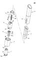
- FIG. 2 shows an exploded view of the rod-shaped material feeding container 100.
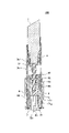
- FIG. 3 shows a cross-sectional view taken along the line I-I of FIG. 1, that is, a cross-sectional view cut along the vertical direction (axial direction)
- FIG. 4 shows a cross-sectional view taken along the line II-II of FIG. 1, that is, the vertical direction.
- FIGS. 1, 3 and 4 show a rod-shaped material feeding container 100 before the rod-shaped material is fed out or in a state where the rod-shaped material is completely contained, that is, in a bottom dead center state.
- the rod-shaped material feeding container 100 has an elongated substantially cylindrical shape as a whole.
- the rod-shaped material feeding container 100 may be provided with a cap 10 for covering from above, as shown by the alternate long and short dash line in FIG.
- the cap 10 may have a shape and a size so that the outer circumferences of the cap 10 and the outer cylinder 8 are flush with each other when the cap 10 is covered.
- the rod-shaped material feeding container 100 includes a rod-shaped material holding portion 3 for holding the rod-shaped material, an outer cylinder 8 that can be operated by the user, and an intermediate mechanism that enables the rod-shaped material to move up and down by rotating the outer cylinder 8.
- a rod-shaped material holding portion 3 for holding the rod-shaped material
- an outer cylinder 8 that can be operated by the user
- an intermediate mechanism that enables the rod-shaped material to move up and down by rotating the outer cylinder 8.
- the rod-shaped material holding portion 3 may have a bottomed cylindrical receiving portion 3a that receives and holds the lower side of the rod-shaped material, and a screw shaft 3b extending downward from the bottom surface of the receiving portion 3a.
- the screw shaft 3b may be solid or hollow, for example cylindrical.
- the rod-shaped material may be directly contained in the receiving portion 3a of the rod-shaped material holding portion 3, or as shown in FIGS. 1 to 4, the rod-shaped material 1 is housed in the middle plate 2, and the middle plate 2 is accommodated. It may be received by the receiving unit 3a. When the middle plate 2 is provided, the rod-shaped material 1 can be easily replaced by making the middle plate 2 detachable from the receiving portion 3a of the rod-shaped material holding portion 3.
- the user can, for example, hold the side peripheral surface of the middle plate 2 and remove or attach the rod-shaped material 1 together with the middle plate 2. That is, the feeding container 100 according to this embodiment can be suitably used as a feeding container in which the rod-shaped material can be exchanged.
- the middle plate 2 is provided with one or more locking protrusions 21 on the side surface, and the locking protrusions 21 are engaged with a notch 31 formed at the upper end of the side portion of the receiving portion 3a of the rod-shaped material holding portion 3. It can be combined (Fig. 2).
- the notch 31 is preferably formed in a substantially L-shape.
- the locking projection 21 of the middle plate 2 is inserted into the substantially L-shaped notch 31 of the receiving portion 3a from top to bottom, the middle plate 2 is received by the receiving portion 3a, and then the middle plate 2 is received. Can be rotated in the circumferential direction to lock the locking projection 21.
- An external screw (external spiral groove or male screw) 32 may be provided on the outer peripheral surface of the screw shaft 3b of the rod-shaped material holding portion 3.
- the external screw 32 may be formed on the entire outer peripheral surface of the screw shaft 3b, and may be formed on the entire surface of the cylindrical shaft, for example. Further, as long as the function as an external screw can be maintained, the external screw 32 may be formed only on a part of the outer peripheral surface of the screw shaft 3b or may be discontinuous. For example, as shown in FIG. 2, the external screw 32 may be formed on two side surfaces of the outer peripheral surface of the screw shaft 3b that face each other in the radial direction.
- this shape is cut along two parallel surfaces along the vertical direction separated from the axis from the state where the external screw is formed on the entire peripheral surface of the columnar shaft.
- the screw shaft 3b has a shape in which an external screw is partially formed on the side surface of a rod having a substantially elliptical or substantially rectangular cross section.
- the outer cylinder 8 is a tubular member arranged on the outermost side of the rod-shaped material feeding container 100 except for the cap 10.
- the rod-shaped material feeding container 100 is provided with a housing 4 extending almost entirely in the vertical direction of the rod-shaped material feeding container 100 (FIGS. 1 to 4), but the outer cylinder 8 is from the housing cylinder 4. Is also arranged radially outside.
- the casing 4 is a member that accommodates and protects the main portion of the feeding mechanism and the rod-shaped material 1, and surrounds the rod-shaped material 1 in the entire vertical direction in the bottom dead center state.
- the user When feeding out the rod-shaped material, for example, the user holds the housing 4 with one hand, holds the outer cylinder 8 with the other hand, and rotates the outer cylinder 8 relative to the housing 4.
- the feeding container 100 can be operated by.
- An outer cylinder inner screw (inner spiral groove or female screw) 82 is formed on the inner peripheral surface of the outer cylinder 8.
- the outer cylinder inner screw 82 is preferably formed up to the upper end of the outer cylinder 8, but does not have to reach the upper end of the outer cylinder 8.
- the outer cylinder 8 and the rod-shaped material holding portion 3 are connected via an intermediate mechanism. More specifically, the intermediate mechanism has an outer engaging portion formed on the radial outer side of the intermediate mechanism and an inner engaging portion formed on the inner side in the radial direction. Then, on the radial outer side, the outer cylinder inner screw 82 of the outer cylinder 8 and the outer engaging portion of the intermediate mechanism are engaged, and on the radial inner side, the inner engaging portion of the intermediate mechanism and the rod-shaped material holding portion 3 are engaged. It is engaged with the screw shaft 3b.
- the above two engagements (the outer cylinder inner screw 82 of the outer cylinder 8 and the outer engagement portion of the intermediate mechanism) are formed in and out of the radial direction.
- the screw shaft 3b can be moved up and down through the radial outer engagement with and the radial inner engagement between the inner engagement portion of the intermediate mechanism and the screw shaft 3b).
- the intermediate mechanism may have a structure including one or more cylindrical members.
- the intermediate mechanism is formed in the radial direction between the outer cylinder 8 and the screw shaft 3b of the rod-shaped material holding portion 3 and below the receiving portion 3a of the rod-shaped material holding portion 3.
- the ratio of the space that can accommodate the rod-shaped material 1 is increased, the amount of the rod-shaped material 1 can be increased, so that the rod-shaped material can be used for a long period of time, which is preferable.
- the shorter the vertical length of the intermediate mechanism the shorter the length of the structure (including the screw shaft 3b) for feeding the rod-shaped material, and as a result, the feeding length may be shortened.
- the outer cylinder 8 since the outer cylinder 8 is provided on the outermost side in the radial direction, the outer cylinder 8 does not depend on the length of the intermediate mechanism and the length of the screw shaft 3b of the rod-shaped material holding portion 3. You can design the vertical length of. Therefore, by lengthening the vertical length of the outer cylinder 8 and forming the outer cylinder inner screw 82 provided on the inner peripheral surface of the outer cylinder 8 in a wide range in the vertical direction, the outer cylinder 8 is outer. The movable range of the intermediate mechanism engaged with the in-cylinder screw 82 in the vertical direction can be increased. If the movable range of the intermediate mechanism with respect to the outer cylinder 8 in the vertical direction can be increased, the feeding length of the rod-shaped material 1 can be lengthened.
- the outer cylinder 8 is provided on the outermost side, it is not necessary to accommodate the outer cylinder 8 in the lower range of the rod-shaped material holding portion 3. Therefore, for example, as shown in FIG. 3, in the bottom dead center state, the position H2 at the upper end of the outer cylinder inner screw 82 of the outer cylinder 8 is set higher than the position H1 at the lower end of the bottom surface of the receiving portion 3a of the rod-shaped material holding portion 3. It can be raised (position H2 can be closer to the tip of rod 1 than position H1).
- the vertical movable range of the outer engaging portion of the intermediate mechanism (in this embodiment, the protrusion formed on the outer periphery of the first intermediate cylinder 5, which will be described in detail later) of the intermediate mechanism that engages with the outer cylinder inner screw 82 is widened, and the rod shape is formed.
- the material 1 can be fed out longer.
- the rod-shaped material holding portion 3 for holding the rod-shaped material, the outer cylinder 8 that can be operated by the user, and the rod-shaped material can be moved up and down by the rotation of the outer cylinder 8.
- the intermediate mechanism may include an inner cylinder 6, a first intermediate cylinder 5, and a second intermediate cylinder 7 arranged in order from the inside in the radial direction (FIGS. 2 to 4).
- An internal screw (inner spiral groove) 64 is formed on the inner peripheral surface of the inner cylinder 6.
- the inner cylinder inner screw 64 is an inner engaging portion of the above-mentioned intermediate mechanism, and is engaged with the outer screw 32 of the screw shaft 3b of the rod-shaped material holding portion 3. By rotating the inner cylinder screw 64, the screw shaft 3b can move up and down, and the rod-shaped material holding portion 3 and eventually the rod-shaped material 1 can move up and down.
- the inner cylinder 6 is housed in the first intermediate cylinder 5.
- the inner cylinder 6 is held by the first intermediate cylinder 5 so as to be rotatable with respect to the first intermediate cylinder 5 but not vertically movable.
- the first intermediate cylinder 5 is provided with a continuous or discontinuous circumferential convex portion 56 formed along the circumferential direction on the upper end side of the inner peripheral surface thereof (FIG. 3).
- a circumferential rib 62 extending along the circumferential direction is provided at the upper end of the inner cylinder 6.
- the circumferential rib 62 may be continuously formed in the circumferential direction or may be discontinuous in the circumferential direction (FIG. 2).
- the circumferential rib 62 formed at the upper end of the inner cylinder 6 is placed on the circumferential convex portion 56 of the first intermediate cylinder 5, specifically, the upper surface of the first intermediate cylinder 5. It is arranged so as to be sandwiched between the convex portion 56 in the circumferential direction and the convex portion 56 in the circumferential direction.
- the inner cylinder 6 and the first intermediate cylinder 5 can rotate relative to each other, but can move up and down as one.
- the configuration for the inner cylinder 6 and the first intermediate cylinder 5 to rotate relative to each other and cannot move up and down is not limited to the one shown in the drawing.
- a groove is provided on the outer peripheral surface of the inner cylinder 6 and faces the groove.
- a circumferential rib may be provided on the inner peripheral surface of the first intermediate cylinder 5 at a position where the intermediate cylinder 5 is to be rotatably engaged with each other.
- the first intermediate cylinder 5 has an upper surface, and an opening 55 is formed on the upper surface (FIG. 2).
- the screw shaft 3b of the rod-shaped material holding portion 3 is arranged through the opening 55 of the first intermediate cylinder 5 (FIGS. 3 and 4).
- the screw shaft 3b can move up and down with respect to the opening 55, but cannot rotate.
- the shape of the opening 55 may be formed so as to match the shape of the screw shaft 3b of the rod-shaped material holding portion 3 so that the screw shaft 3b cannot rotate with respect to the opening 55. That is, the opening 55 can function as a rotation stopper for the rod-shaped material holding portion 3.
- the bulging portions 53, 53 may be formed at the edge of the opening 55 of the first intermediate cylinder 5.
- the screw shaft 3b of the rod-shaped material holding portion 3 is formed with a ridge portion 33 along the vertical direction. Since the ridge portion 33 can be vertically and vertically movably engaged between the bulging portions 53 and 53 formed in the opening 55 of the first intermediate cylinder 5, the screw shaft 3b can be stably moved up and down.
- the first intermediate cylinder 5 is provided with a protrusion 52 on its outer peripheral surface, and this protrusion 52 can be engaged with the outer cylinder inner screw 82 of the outer cylinder 8 (FIG. 4). Further, the protrusion 52 of the first intermediate cylinder 5 is formed so as to be able to move up and down in the slit 41 (FIG. 2) formed along the vertical direction in the housing cylinder 4 arranged on the outside of the first intermediate cylinder 5. ing. Therefore, when the user rotates the outer cylinder 8 with respect to the housing 4, the first intermediate cylinder 5 can move up and down along the slit 41 of the housing 4.
- the protrusions 52 of the first intermediate cylinder 5 are formed at two positions facing each other in the radial direction on the lower end side of the first intermediate cylinder 5, but three or more protrusions 52 are provided on the outer peripheral surface. May be. Further, the slit 41 of the housing tube 4 is formed for each protrusion 52.
- a second intermediate cylinder 7 is arranged between the inner cylinder 6 and the first intermediate cylinder 5.
- the vertical rib 61r of the inner cylinder 6 and the vertical groove 71g of the second intermediate cylinder 7 are engaged with each other, and the vertical groove 61g of the inner cylinder 6 and the vertical groove 7 of the second intermediate cylinder 7 are engaged with each other.
- the second intermediate cylinder 7 is provided with a flange 72 protruding in the radial direction at the lower end.
- the second intermediate cylinder 7 can be inserted into the outer cylinder 8 from below the outer cylinder 8 and mounted.
- the flange 72 of the second intermediate cylinder 7 is attached to the outer cylinder. It can abut on the lower end surface of No. 8 (FIGS. 3 and 4).
- the flange 72 is not continuously formed in the circumferential direction, and may be provided with one or more notches 72c.
- a lower end surface protrusion 85 (FIGS.
- the outer cylinder 8 and the second intermediate cylinder 7 may be formed on the lower end surface of the outer cylinder 8, and by this fitting, the outer cylinder 8 and the second intermediate cylinder 7 may be formed. Is fitted and fixed.
- the outer cylinder 8 and the second intermediate cylinder 7 move integrally. That is, when the outer cylinder 8 is rotated, the second intermediate cylinder 7 can also be rotated integrally with the outer cylinder 8. Further, the second intermediate cylinder 7 does not move up and down with respect to the outer cylinder 8.
- the configuration in which the second intermediate cylinder 7 is fixed to the outer cylinder 8 is not limited to the above, and for example, the flange 72 of the second intermediate cylinder 7 may be adhered to the lower end surface of the outer cylinder 8.
- the first intermediate cylinder 5 can move up and down with respect to the outer cylinder 8 by rotating the outer cylinder 8.
- the second intermediate cylinder 7 is fixed to the outer cylinder 8, cannot move up and down and cannot rotate relative to the outer cylinder 8, and can rotate together with the outer cylinder 8.
- the inner cylinder 6 is housed in the feeding container 100 so as to be vertically movable by the first intermediate cylinder 5 and rotatably by the second intermediate cylinder 7.
- the user rotates the outer cylinder 8 with respect to the casing 4 about the axis (center line along the vertical direction) in the feeding container 100 in the bottom dead center state as shown in FIG.
- the outer cylinder inner screw (female screw) 82 of the outer cylinder 8 rotates, so that the protrusion 52 of the first intermediate cylinder 5 engaged with the outer cylinder inner screw 82 rises.
- the entire first intermediate cylinder 5 rises. That is, when the user rotates the outer cylinder 8 with respect to the casing 4, the first intermediate cylinder 5 moves up and down without rotating relative to the casing 4.
- FIG. 5 shows a state after one rotation of the outer cylinder 8 from the bottom dead center state of the feeding container 100 shown in FIG.
- FIG. 6 shows the top dead center state of the feeding container 100 after the outer cylinder 8 is further rotated from the state of FIG.
- the first intermediate cylinder 5 is raised with respect to the outer cylinder 8.
- the inner cylinder 6 is housed in the first intermediate cylinder 5, but since the circumferential rib 62 at the upper end of the inner cylinder 6 is arranged on the circumferential convex portion 56 of the first intermediate cylinder 5, the first intermediate cylinder 5 is accommodated. 1
- the inner cylinder 6 housed in the first intermediate cylinder 5 also rises.
- the screw shaft 3b having the external screw 32 engaged with the inner cylinder inner screw 64 of the inner cylinder 6 rises, and eventually the rod-shaped material holding portion 3 rises.
- the second intermediate cylinder 7 fixed to the outer cylinder 8 also rotates.
- the second intermediate cylinder 7 is provided with a flange 72 formed at the lower end, and the notch 72c of the flange 72 is fitted to the lower end surface protrusion 85 of the outer cylinder 8. Therefore, as described above, the outer cylinder 8 and the second intermediate cylinder 7 are fitted.
- the intermediate cylinder 7 is relatively non-rotatable and relatively non-movable up and down. Therefore, when the user rotates the outer cylinder 8 with respect to the casing 4, the second intermediate cylinder 7 rotates relative to the casing 4 without moving up and down. Then, as the second intermediate cylinder 7 rotates, the inner cylinder 6 engaged with the second intermediate cylinder 7 also rotates integrally. That is, the inner cylinder 6 rotates with respect to the first intermediate cylinder 5 in the first intermediate cylinder 5.
- the outer screw 32 of the screw shaft 3b of the rod-shaped material holding portion 3 is screwed into the inner screw 64 of the inner cylinder 6 formed on the inner peripheral surface of the inner cylinder 6. Since the screw shaft 3b cannot rotate with respect to the first intermediate cylinder 5 as described above, the screw shaft 3b rises as the inner cylinder 6 rotates with respect to the first intermediate cylinder 5. As a result, the rod-shaped material holding portion 3 rises.
- the inner cylinder 6 rises relatively with respect to the casing 4 via the first intermediate cylinder 5, and the second intermediate cylinder 6 is raised.
- the inner cylinder 6 rotates relative to the casing 4 via the cylinder 7. That is, due to the rotation of the outer cylinder 8, the inner cylinder 6 rises via the first intermediate cylinder 5 and at the same time rotates via the second intermediate cylinder 7.
- the rotation of the outer cylinder 8 not only causes the inner cylinder 6 to rotate or rise, but also allows the inner cylinder 6 to rotate while ascending. Can be obtained.
- the ascending stroke of the screw shaft 3b can be obtained by ascending the inner cylinder 6 itself, and the ascending stroke of the screw shaft 3b screwed with the inner cylinder 6 is also obtained by the rotation of the inner cylinder 6.
- a stroke is obtained.
- the former ascending stroke that is, the ascending stroke due to the ascending of the inner cylinder 6 itself (the ascending stroke due to the function of the first intermediate cylinder 5 ) is set to ⁇ h5
- the latter ascending stroke that is, the ascending stroke due to the rotation of the inner cylinder 6 (the first).
- the first intermediate cylinder 5, the second intermediate cylinder 7, and the inner cylinder 6 included in the intermediate mechanism are housed below the lower end of the receiving portion 3a of the rod-shaped material holding portion 3.
- the intermediate mechanism which occupies a large part of the feeding mechanism, is compactly configured.
- the outer cylinder 8 is formed longer than the intermediate mechanism, and the upper end of the outer cylinder inner screw 82 is located above the lower end of the bottom surface of the receiving portion 3a in the bottom dead center state. The feeding length of the rod-shaped material can be increased.
- the feeding length of the rod-shaped material can be lengthened without allocating the storage space for the rod-shaped material to the storage space of the intermediate mechanism. Therefore, as shown in FIG. 6, the rod-shaped material 1 can be raised and fed out until the middle plate 2 accommodating the rod-shaped material 1 is exposed.
- Each member of the rod-shaped material feeding container 100 may be made of resin or metal.
- the resin include AS (acrylonitrile / styrene), ABS (acrylonitrile / butadiene / styrene), PP (polypropylene), POM (polyacetal), UHMWPE (ultra high molecular weight polyethylene) and the like, and engineering plastics can also be used. Further, if it is a metal, aluminum or the like can be used.
Landscapes
- Engineering & Computer Science (AREA)
- Mechanical Engineering (AREA)
- Containers And Packaging Bodies Having A Special Means To Remove Contents (AREA)
- Mechanical Pencils And Projecting And Retracting Systems Therefor, And Multi-System Writing Instruments (AREA)
Abstract
棒状材を受容する受容部と、前記受容部の底面から下方に延びるねじシャフトとを有する棒状材保持部と、外筒と、前記外筒の回転によって前記ねじシャフトの上下動を可能にする中間機構とを備える棒状材繰出容器であって、前記外筒が外筒内ねじを備え、前記中間機構が、前記ねじシャフトと係合する内側係合部と、前記外筒内ねじと係合する外側係合部とを備えており、前記外筒が、前記受容部より径方向外側に配置され、下死点状態で、前記外筒内ねじの上端が、前記受容部の底面の下端より上に位置する。
Description
本発明は、棒状材繰出容器に関する。
棒状材繰出容器の繰出構造として、いわゆる二重螺旋構造が知られている(例えば、特許文献1、2)。二重螺旋構造においては、周面に螺旋溝が設けられた螺旋部材が径方向内外で2つ設けられている。螺旋部材の螺旋溝は隣接部材と係合しており、この係合によって回転運動を上下運動に変換できるので、使用者の回転操作によって螺旋部材を容易に上昇させて繰り出すことができる。二重螺旋構造を有する繰出容器では、2つの螺旋部材それぞれが繰り出された長さが棒状材の繰出し長さ(操作によって棒状材が上昇するストローク)として加算される。よって、繰出機構を上下方向にコンパクトに構成しつつも、繰出し長さを大きくできる。
繰出容器としては、棒状材を交換可能に構成されたものも知られている。このような繰出容器においては、棒状材を交換しやすいように、棒状材を繰り出した際に棒状材の下端までが露出するように構成することが好ましい。このように、棒状材の繰出し長さを、より一層長くすることが望まれる場合がある。
従来の二重螺旋構造を備えた棒状材繰出容器では、螺旋部材を含む繰出機構は、棒状材の下端よりも下側に収容されている。よって、繰出し長さをさらに長くするためには、繰出機構を長くする必要があり、そうなると棒状材繰出容器の全体を長くせざるを得ない。棒状材繰出容器全体の長さが長くなると、持ち運び又は取り扱いが不都合になり得るため、好まれない場合がある。一方、繰出容器全体の長さを変えずに、棒状材より下側にある繰出し機構を長くすると、棒状材の長さを短くせざるを得ず、使用できる棒状材の量が減ってしまい、棒状材を短期間でしか使用できない。
よって、本発明の一態様は、全体の長さを短く維持しつつ、棒状材の繰出し長さをより一層長くした棒状材繰出容器を提供することを課題とする。
上記課題を解決するため、本発明の一態様では、棒状材を受容する受容部と、前記受容部の底面から下方に延びるねじシャフトとを有する棒状材保持部(3)と、外筒(8)と、前記外筒(8)の回転によって前記ねじシャフトの上下動を可能にする中間機構(5、6、7)とを備える棒状材繰出容器であって、前記外筒(8)が外筒内ねじを備え、前記中間機構(5、6、7)が、前記ねじシャフトと係合する内側係合部と、前記外筒内ねじと係合する外側係合部とを備えており、前記外筒(8)が、前記受容部より径方向外側に配置され、下死点状態で、前記外筒内ねじの上端が、前記受容部の底面の下端より上に位置する。
一態様によれば、棒状材繰出容器において、全体の長さを短く維持しつつ、棒状材の繰出し長さを大きくした棒状材繰出容器を提供できる。
以下、本発明の実施の形態について図面を参照しながら説明する。本発明の一形態は、棒状材(スティック状材)の繰出容器である。棒状材は、所定の形状に形成された固体、或いは静止状態で所定の形状を維持可能な形態であってよい。
本形態による繰出容器は、棒状化粧料の繰出容器として好適に使用できる。棒状化粧料の具体例としては、口紅、リップクリーム、コンシーラー、スティックアイシャドウ、スティックチーク、スティックファンデーション等が挙げられる。また、美容液(美容剤)、保湿剤、美白剤等の、所定の機能を備えた化粧料を棒状に成形したものであってもよい。また、棒状材は、化粧材以外のもの、例えば、制汗剤、日焼け止め、染毛剤、練り香水、虫除け等のパーソナルケア製品(衛生日用品)であってよい。さらに、棒状材は、固体洗剤、糊、接着剤、消しゴム、化粧料を模したおもちゃ等であってもよい。
図1に、本形態による棒状材繰出容器100の斜視図を示す。また、図2に、棒状材繰出容器100の分解図を示す。さらに、図3に、図1のI-I線断面図、すなわち上下方向(軸方向)に沿って切った断面図を示し、図4に、図1のII-II線断面図、すなわち上下方向であるが、I-I線断面に直交する断面で切った図を示す。図1、図3及び図4には、棒状材が繰り出される前の、若しくは棒状材が完全に収容された状態、すなわち下死点状態にある棒状材繰出容器100を示す。
図1に示すように、棒状材繰出容器100は、全体として細長の略円筒形状を有する。棒状材繰出容器100は、図4に一点鎖線で示すような、上から被せるためのキャップ10を備えていてよい。キャップ10は、キャップ10を被せた状態では、キャップ10及び外筒8の外周が面一になるような形状及びサイズを有していてよい。
棒状材繰出容器100は、棒状材を保持する棒状材保持部3と、使用者が操作可能な外筒8と、外筒8の回転によって棒状材の上下動を可能にする中間機構とを、基本要素として備える。
棒状材保持部3は、棒状材の下側を受容して保持する有底円筒形状の受容部3aと、受容部3aの底面から下方に延びるねじシャフト3bとを有していてよい。ねじシャフト3bは中実であってもよいし、中空、例えば円筒状であってもよい。棒状材保持部3の受容部3aには、棒状材が直接収容されていてもよいし、図1~図4に示すように、棒状材1を中皿2に収容し、その中皿2が受容部3aによって受容されていてもよい。中皿2を備えている場合、中皿2を、棒状材保持部3の受容部3aに着脱可能に構成しておくことで、棒状材1を容易に交換できる。交換時には、使用者は、例えば中皿2の側周面を持って、中皿2と共に棒状材1を取り外したり、取り付けたりできる。すなわち、本形態による繰出容器100は、棒状材を交換可能な繰出容器として好適に使用され得る。中皿2には、側面に1以上の係止突起21が設けられており、この係止突起21は、棒状材保持部3の受容部3aの側部の上端に形成された切欠31と係合できる(図2)。切欠31は、好ましくは略L字形状に形成されている。その場合、中皿2の係止突起21を受容部3aの略L字形状の切欠き31に上から下へ挿入するようにして、中皿2を受容部3aによって受容した後、中皿2を周方向に回転させて、係止突起21を係止することができる。
棒状材保持部3のねじシャフト3bの外周面には、外ねじ(外螺旋溝若しくは雄ねじ)32が設けられていてよい。外ねじ32は、ねじシャフト3bの外周面全体に形成されていてよく、例えば円柱状のシャフトの表面全体に形成されていてよい。また、外ねじとしての機能を維持できるのであれば、ねじシャフト3bの外周面の一部のみに形成されている、若しくは外ねじ32が不連続になっていてよい。例えば、図2に示すように、外ねじ32は、ねじシャフト3bの外周面のうち径方向で対向する2つの側面に形成されていてもよい。この形状は、円柱状のシャフトの周面全体に外ねじが形成された状態から、軸線から離間した上下方向に沿った互いに平行な2つの面に沿って切断した形状といえる。或いは、ねじシャフト3bは、略楕円形又は略長方形の断面を有するロッドの側面に部分的に外ねじが形成されてなる形状ともいえる。
外筒8は、キャップ10を除いて、棒状材繰出容器100の最も外側に配置される筒状部材である。棒状材繰出容器100には、棒状材繰出容器100の上下方向にわたってほぼ全体に延在する筐筒4が設けられているが(図1~図4)、外筒8は、この筐筒4よりも径方向外側に配置されている。なお、筐筒4は、繰出機構の主要部及び棒状材1を収容して保護する部材であり、下死点状態では棒状材1を上下方向全体にわたって取り囲んでいる。
使用者は、棒状材を繰り出す際には、例えば、筐筒4を一方の手で押さえ、もう一方の手で外筒8を持って、この外筒8を筐筒4に対し相対回転させることによって繰出容器100を操作できる。
外筒8の内周面には、外筒内ねじ(内螺旋溝若しくは雌ねじ)82が形成されている。外筒内ねじ82は、外筒8の上端まで形成されていると好ましいが、外筒8の上端に達していなくともよい。
外筒8と棒状材保持部3とは、中間機構を介して接続されている。より具体的には、中間機構が、当該中間機構の径方向外側に形成された外側係合部と、径方向内側に形成された内側係合部とを有している。そして、径方向外側で、外筒8の外筒内ねじ82と中間機構の外側係合部とが係合し、また径方向内側で、中間機構の内側係合部と棒状材保持部3のねじシャフト3bとが係合している。棒状材を繰り出す際、使用者が外筒8を回転させると、径方向内外にて形成される上記の2箇所の係合(外筒8の外筒内ねじ82と中間機構の外側係合部との径方向外側の係合、及び中間機構の内側係合部とねじシャフト3bとの径方向内側の係合)を介して、ねじシャフト3bを上下動させることができる。
中間機構は、1以上の筒状の部材を含む構造であってよい。中間機構は、径方向で、外筒8と棒状材保持部3のねじシャフト3bとの間に、且つ棒状材保持部3の受容部3aの下側に形成されている。中間機構をできるだけ短くコンパクトに構成することによって、中間機構の上端位置をより下方に近づけることができるため、棒状材保持部3の受容部3aをより下方に配置させることができる。これにより、棒状材1が収容される空間の割合を、上下方向により大きく確保できる。棒状材1を収容できる空間の割合が増えれば、棒状材1の量を増加できることになるので、棒状材を長期間使用することができ、好ましい。しかしながら、中間機構の上下方向長さを短くするほど、棒状材を繰り出すための構造(ねじシャフト3bを含む)の長さが短くなり、結果として繰出し長さが短くなり得る。
これに対し、本形態では、外筒8を径方向で最も外側に設けているため、中間機構の長さ及び棒状材保持部3のねじシャフト3bの長さに依存することなく、外筒8の上下方向長さを設計できる。よって、外筒8の上下方向長さを長くして、それに伴い外筒8の内周面に設けられた外筒内ねじ82も上下方向に広い範囲に形成することで、外筒8の外筒内ねじ82に係合する中間機構の上下方向での可動範囲を増やすことができる。外筒8に対する中間機構の上下方向の可動範囲を増やすことができれば、棒状材1の繰出し長さを長くできる。
このように、外筒8が最も外側に設けられていることで、外筒8を棒状材保持部3の下側の範囲に収容する必要がない。よって、例えば図3に示すように、下死点状態で、外筒8の外筒内ねじ82の上端の位置H2を、棒状材保持部3の受容部3aの底面の下端の位置H1よりも高くすることができる(位置H2を、位置H1よりも棒状材1の先端に近付けることができる)。これにより、外筒内ねじ82と係合する中間機構の外側係合部(本形態では第1中間筒5の外周に形成された突起、後に詳述)の上下方向の可動範囲が広がり、棒状材1をより長く繰り出すことができる。
続いて、繰出容器100のさらに具体的な構成について説明する。上述のように、本形態による繰出容器100は、棒状材を保持する棒状材保持部3と、使用者が操作可能な外筒8と、外筒8の回転によって棒状材の上下動を可能にする中間機構とを備えている。ここで、中間機構は、径方向内側から順に配置された内筒6、第1中間筒5、及び第2中間筒7を備えていてよい(図2~図4)。
内筒6の内周面には、内ねじ(内螺旋溝)64が形成されている。内筒内ねじ64は、上述の中間機構の内側係合部であって、棒状材保持部3のねじシャフト3bの外ねじ32に係合している。内筒内ねじ64が回転することで、ねじシャフト3bが上下動し、棒状材保持部3、ひいては棒状材1が上下動することができる。
内筒6は、第1中間筒5内に収容されている。そして、内筒6は、第1中間筒5によって、第1中間筒5に対して回転可能であるが上下動不能に保持されている。より具体的には、第1中間筒5は、その内周面の上端側に、周方向に沿って形成された連続又は不連続の周方向凸部56を備えている(図3)。一方、内筒6の上端には、周方向に沿って延びる周方向リブ62が設けられている。周方向リブ62は、周方向に連続して形成されていてもよいし、周方向で不連続になっていてもよい(図2)。組み立てられた繰出容器100においては、内筒6の上端に形成された周方向リブ62は、第1中間筒5の周方向凸部56の上に、具体的には第1中間筒5の上面と周方向凸部56とに挟まれて配置されている。これにより、内筒6と第1中間筒5とは、相対回転可能であるが、一体となって上下動することができる。なお、内筒6と第1中間筒5とが相対回転であり且つ上下動不能となるための構成は図示のものに限られず、例えば内筒6の外周面に溝を設け、この溝に対向する位置に第1中間筒5の内周面に周方向リブを設けておき、両者を回転可能に係合させてもよい。
第1中間筒5は上面を備え、この上面には開口55が形成されている(図2)。組み立てられた状態で、第1中間筒5の開口55には、棒状材保持部3のねじシャフト3bが貫通して配置される(図3及び図4)。ねじシャフト3bは、開口55に対して上下動可能であるが、回転不能となっている。開口55の形状は、ねじシャフト3bが開口55に対して回転不能となるように、棒状材保持部3のねじシャフト3bの形状に適合するように形成されていてよい。すなわち、開口55は、棒状材保持部3のための回転止めとして機能し得る。
第1中間筒5の開口55の縁部には、膨出部53、53が形成されていてよい。一方、棒状材保持部3のねじシャフト3bには上下方向に沿った畝部33が形成されている。この畝部33は、第1中間筒5の開口55に形成された膨出部53、53の間に上下動可能に係合することができるので、ねじシャフト3bが安定して上下動できる。
第1中間筒5は、その外周面に突起52を備えており、この突起52は、外筒8の外筒内ねじ82と係合できる(図4)。また、第1中間筒5の突起52は、第1中間筒5の外側に配置される筐筒4に上下方向に沿って形成されたスリット41(図2)内を上下動できるように形成されている。そのため、使用者が筐筒4に対して外筒8を回転した場合、第1中間筒5が、筐筒4のスリット41に沿って上下動することができる。
図示の形態では、第1中間筒5の突起52は、第1中間筒5の下端側に、径方向で対向する2箇所に形成されているが、突起52は外周面に3つ以上設けられていてもよい。また、筐筒4のスリット41は、突起52ごとに形成されている。
内筒6と第1中間筒5との間には、第2中間筒7が配置されている。内筒6の外周面には、上下方向に沿って延びる複数の上下方向リブ61r、61r、…及び上下方向リブ61r、61r、…間の複数の上下方向溝61g、61g、…が形成されていてよい(図2)。一方、第2中間筒7の内周面には、上下方向に沿って延びる複数の上下方向溝71g、71g、…及び上下方向溝71g、71g、…間の複数の上下方向リブ71r、71r、…が形成されていてよい(図2)。そして、組み立てられた状態では、内筒6の上下方向リブ61rと第2中間筒7の上下方向溝71gとが係合し、内筒6の上下方向溝61gと第2中間筒7の上下方向リブ71rとが係合する。よって、内筒6と第2中間筒7とは、互いに相対的に上下動可能(摺動可能)であるが、相対回転不能となっている。そのため、第2中間筒7を回転させると、内筒6は第2中間筒7と一体となって回転できる。
第2中間筒7は、下端に、径方向に突出するフランジ72を備えている。第2中間筒7は、組み立ての際には、外筒8の下方から外筒8内へと挿入させて装着することができるが、その際、第2中間筒7のフランジ72は、外筒8の下端面に当接することができる(図3及び図4)。さらに、フランジ72は周方向に連続して形成されておらず、1つ以上の切欠き72cが設けられていてよい。外筒8の下端面には、切欠き72cに嵌合可能な下端面突起85(図5及び図6)が形成されていてよく、この嵌合により、外筒8と第2中間筒7とが嵌合されて固定される。外筒8と第2中間筒7が固定されることで、外筒8と第2中間筒7とは一体的に運動する。すなわち、外筒8を回転させた場合に第2中間筒7も外筒8と一体となって回転できる。また、第2中間筒7は、外筒8に対して上下動することもない。なお、第2中間筒7が外筒8に固定される構成は、上述のものに限らず、例えば第2中間筒7のフランジ72を外筒8の下端面に接着させてもよい。
このように、第1中間筒5は、外筒8を回転させることで、外筒8に対して上下動可能となっている。また、第2中間筒7は外筒8に固定されており、外筒8に対して相対的に上下動及び回転不能であり、外筒8と共に回転できる。さらに、内筒6は、第1中間筒5によって上下動可能に、且つ第2中間筒7によって回転可能に、繰出容器100内に収容されている。
次に、繰出容器100から棒状材を繰り出す際の各部材の動きについて説明する。まず、使用者は、図3に示すような下死点状態にある繰出容器100において、外筒8を、軸線(上下方向に沿った中心線)を中心として筐筒4に対し回転させる。外筒8が回転することによって、外筒8の外筒内ねじ(雌ねじ)82が回転するので、これにより外筒内ねじ82と係合している第1中間筒5の突起52が上昇して、第1中間筒5全体が上昇する。すなわち、使用者が外筒8を筐筒4に対して回転させることによって、第1中間筒5は、筐筒4に対して相対回転することなく上下動する。
図5に、図3に示す繰出容器100の下死点状態から、外筒8を1回転した後の状態を示す。また、図6に、図5の状態からさらに外筒8を回転させた後の、繰出容器100の上死点状態を示す。
図5に示すように、第1中間筒5は、外筒8に対して上昇している。第1中間筒5内には内筒6が収容されているが、内筒6の上端の周方向リブ62が第1中間筒5の周方向凸部56の上に配置されているので、第1中間筒5の上昇に伴って、第1中間筒5内に収容されている内筒6も上昇する。そして、内筒6が上昇することで、内筒6の内筒内ねじ64に係合している外ねじ32を備えているねじシャフト3bが上昇し、ひいては棒状材保持部3が上昇する。
また、使用者が外筒8を筐筒4に対して回転させると、外筒8に固定されている第2中間筒7も回転する。第2中間筒7は下端に形成されたフランジ72を備え、フランジ72の切欠き72cが外筒8の下端面突起85と嵌合しているので、上述のように、外筒8と第2中間筒7とは、相対的に回転不能であり且つ相対的に上下動不能となっている。そのため、使用者が外筒8を筐筒4に対して回転させることによって、第2中間筒7は、上下動することなく筐筒4に対して相対回転する。そして、第2中間筒7が回転することで、第2中間筒7と係合している内筒6も一体となって回転する。すなわち、内筒6は、第1中間筒5内で、第1中間筒5に対して回転する。
内筒6の内周面に形成されている内筒6内ねじ64には、棒状材保持部3のねじシャフト3bの外ねじ32が螺合している。そして、ねじシャフト3bは上述のように第1中間筒5に対して回転不能となっているので、内筒6が第1中間筒5に対して回転することで、ねじシャフト3bが上昇し、ひいては棒状材保持部3が上昇する。
このように、使用者が外筒8を筐筒4に対して回転させることによって、第1中間筒5を介して内筒6が筐筒4に対して相対的に上昇し、且つ第2中間筒7を介して内筒6が筐筒4に対して相対回転する。すなわち、外筒8の回転によって、内筒6は、第1中間筒5を介して上昇すると同時に、第2中間筒7を介して回転する。本形態によれば、外筒8の回転によって内筒6が単に回転又は上昇するだけでなく、上昇しつつ回転できるので、外筒8の小さな回転運動で或いは少ない労力でも、より長い繰り出し長さを得ることができる。
より具体的に言うと、内筒6自体が上昇することによって、ねじシャフト3bの上昇ストロークが得られる上、内筒6の回転によっても、内筒6と螺合しているねじシャフト3bの上昇ストロークが得られる。前者の上昇ストローク、すなわち内筒6自体の上昇による上昇ストローク(第1中間筒5の機能に起因する上昇ストローク)をΔh5とし、後者の上昇ストローク、すなわち内筒6の回転による上昇ストローク(第2中間筒7の機能に起因する上昇ストローク)をΔh7とした場合、ねじシャフト3b(又は棒状材保持部3)の上昇ストローク(トータルストローク)をΔhtとすると、Δht=Δh5+Δh7となる。
また、本形態によれば、中間機構に含まれる第1中間筒5、第2中間筒7、及び内筒6が、棒状材保持部3の受容部3aの下端より下側に収容されていて、繰出機構の大きな部分を占める中間機構がコンパクトに構成されている。一方、上述のように外筒8は中間機構に対して長く形成されていて、下死点状態で外筒内ねじ82の上端が受容部3aの底面の下端より上に位置しているので、棒状材の繰出し長さは長くすることができる。よって、従来と同じ全長を有する繰出容器全体において、棒状材の収容空間を中間機構の収容空間に配分することなく、棒状材の繰出し長さを長くできる。そのため、図6に示すように、棒状材1を収容する中皿2が露出するまで棒状材1を上昇させて繰り出すことができる。
棒状材繰出容器100の各部材は、樹脂又は金属で形成されていてよい。樹脂として例えば、AS(アクリロニトリル・スチレン)、ABS(アクリロニトリル・ブタジエン・スチレン)、PP(ポリプロピレン)、POM(ポリアセタール)、UHMWPE(超高分子量ポリエチレン)等が挙げられ、エンジニアリングプラスチックも使用され得る。また、金属であれば、アルミニウム等を使用できる。
本出願は、2020年12月22日に日本国特許庁に出願された特願2020-212625号に基づく優先権を主張するものであり、その全内容を参照によりここに援用する。
1 棒状材
2 中皿
10 キャップ
21 係止突起
3 棒状材保持部
3a 受容部
3b ねじシャフト
32 外ねじ
4 筐筒
41 スリット
5 第1中間筒
52 突起
55 開口
53 開口縁部の膨出部
56 周方向凸部
6 内筒
61g 内筒の上下方向溝
61r 内筒の上下方向リブ
62 周方向リブ
7 第2中間筒
71g 第2中間筒の上下方向溝
71r 第2中間筒の上下方向リブ
72 フランジ
72c フランジの切欠き
8 外筒
82 外筒内ねじ
85 下端面突起
100 棒状材繰出容器
2 中皿
10 キャップ
21 係止突起
3 棒状材保持部
3a 受容部
3b ねじシャフト
32 外ねじ
4 筐筒
41 スリット
5 第1中間筒
52 突起
55 開口
53 開口縁部の膨出部
56 周方向凸部
6 内筒
61g 内筒の上下方向溝
61r 内筒の上下方向リブ
62 周方向リブ
7 第2中間筒
71g 第2中間筒の上下方向溝
71r 第2中間筒の上下方向リブ
72 フランジ
72c フランジの切欠き
8 外筒
82 外筒内ねじ
85 下端面突起
100 棒状材繰出容器
Claims (9)
- 棒状材を受容する受容部と、前記受容部の底面から下方に延びるねじシャフトとを有する棒状材保持部と、
外筒と、
前記外筒の回転によって前記ねじシャフトの上下動を可能にする中間機構と
を備える棒状材繰出容器であって、
前記外筒が外筒内ねじを備え、
前記中間機構が、前記ねじシャフトと係合する内側係合部と、前記外筒内ねじと係合する外側係合部とを備えており、
前記外筒が、前記受容部より径方向外側に配置され、
下死点状態で、前記外筒内ねじの上端が、前記受容部の底面の下端より上に位置する、棒状材繰出容器。 - 前記中間機構が、
前記ねじシャフトと螺合する内筒内ねじを備えた内筒と、
前記内筒を回転可能に保持し、前記内筒と一体となって前記外筒に対して上下動する第1中間筒と、
前記内筒と一体となって回転可能な第2中間筒と
を備える、請求項1に記載の棒状材繰出容器。 - 前記外筒の回転によって、前記第1中間筒が前記外筒に対して上下動すると共に、前記外筒と一体となって前記第2中間筒が回転して前記内筒が回転し、前記棒状材保持部が前記内筒に対して上下動する、請求項2に記載の棒状材繰出容器。
- 前記第1中間筒の外周面に突起が設けられており、前記突起が、前記外筒の前記外筒内ねじに係合する、請求項2又は3に記載の棒状材繰出容器。
- 前記内筒の外周面に周方向リブが設けられ、前記第1中間筒の内周面に前記周方向リブが載置される周方向凸部が設けられている、請求項2から4のいずれか一項に記載の棒状材繰出容器。
- 前記第2中間筒が下端にフランジを備え、前記フランジが、前記外筒の下端面に形成された突起に係合する、請求項2から5のいずれか一項に記載の棒状材繰出容器。
- 前記内筒及び前記第2中間筒の一方の対向面に上下方向溝が設けられ、他方に前記上下方向溝と係合する上下方向リブが設けられている、請求項2から4のいずれか一項に記載の棒状材繰出容器。
- 前記第2中間筒の上部に、前記棒状材保持部を前記第2中間筒に対して相対的に回転不能にする回転止めが設けられている、請求項2から7のいずれか一項に記載の棒状材繰出容器。
- 前記棒状材が化粧料である、請求項1から8のいずれか一項に記載の棒状材繰出容器。
Applications Claiming Priority (2)
| Application Number | Priority Date | Filing Date | Title |
|---|---|---|---|
| JP2020-212625 | 2020-12-22 | ||
| JP2020212625A JP7699926B2 (ja) | 2020-12-22 | 2020-12-22 | 棒状材繰出容器 |
Publications (1)
| Publication Number | Publication Date |
|---|---|
| WO2022138363A1 true WO2022138363A1 (ja) | 2022-06-30 |
Family
ID=82159722
Family Applications (1)
| Application Number | Title | Priority Date | Filing Date |
|---|---|---|---|
| PCT/JP2021/046205 Ceased WO2022138363A1 (ja) | 2020-12-22 | 2021-12-15 | 棒状材繰出容器 |
Country Status (2)
| Country | Link |
|---|---|
| JP (1) | JP7699926B2 (ja) |
| WO (1) | WO2022138363A1 (ja) |
Families Citing this family (1)
| Publication number | Priority date | Publication date | Assignee | Title |
|---|---|---|---|---|
| KR102704981B1 (ko) * | 2023-04-04 | 2024-09-06 | 주식회사 삼화 | 슬림형 스틱 용기 |
Citations (3)
| Publication number | Priority date | Publication date | Assignee | Title |
|---|---|---|---|---|
| JPS6455814U (ja) * | 1987-10-02 | 1989-04-06 | ||
| JP2008055025A (ja) * | 2006-09-01 | 2008-03-13 | Suzuno Kasei Kk | 棒状化粧材繰り出し容器 |
| US20200288845A1 (en) * | 2019-03-12 | 2020-09-17 | HCT Group Holdings Limited | Eco-friendly cosmetic container |
-
2020
- 2020-12-22 JP JP2020212625A patent/JP7699926B2/ja active Active
-
2021
- 2021-12-15 WO PCT/JP2021/046205 patent/WO2022138363A1/ja not_active Ceased
Patent Citations (3)
| Publication number | Priority date | Publication date | Assignee | Title |
|---|---|---|---|---|
| JPS6455814U (ja) * | 1987-10-02 | 1989-04-06 | ||
| JP2008055025A (ja) * | 2006-09-01 | 2008-03-13 | Suzuno Kasei Kk | 棒状化粧材繰り出し容器 |
| US20200288845A1 (en) * | 2019-03-12 | 2020-09-17 | HCT Group Holdings Limited | Eco-friendly cosmetic container |
Also Published As
| Publication number | Publication date |
|---|---|
| JP2022098938A (ja) | 2022-07-04 |
| JP7699926B2 (ja) | 2025-06-30 |
Similar Documents
| Publication | Publication Date | Title |
|---|---|---|
| JP4943509B2 (ja) | 運動が切り離された一体の化粧用コンパクト | |
| CN107568878A (zh) | 双头化妆品容器 | |
| CN101909481A (zh) | 用于双棒形物运动的具有单一棒形物支撑件的容器 | |
| US20180020808A1 (en) | Telescoping container for liquid cosmetic product | |
| JP4155358B2 (ja) | 棒状化粧料繰り出し容器 | |
| WO2022138363A1 (ja) | 棒状材繰出容器 | |
| KR20200000957U (ko) | 듀얼 타입 립스틱 용기의 립스틱 홀더 승강구조 | |
| US3789857A (en) | Stick type cosmetic applicator | |
| KR102522454B1 (ko) | 간섭방지형 립스틱 용기 | |
| US11882915B2 (en) | Refillable container | |
| WO2000076367A1 (en) | Make-up material container | |
| US7172356B2 (en) | Packaging and dispensing device with disengaging mechanism | |
| JP7466273B2 (ja) | 繰出容器 | |
| CN210227246U (zh) | 用于棒状材料的容器 | |
| JP7203601B2 (ja) | 繰出容器 | |
| JP2018029744A (ja) | 棒状化粧料繰り出し容器 | |
| JP4192280B2 (ja) | 化粧料等の繰出容器 | |
| JP2598285Y2 (ja) | 棒状化粧料繰り出し容器 | |
| JP2576226Y2 (ja) | 棒状化粧料繰り出し容器 | |
| US12478164B2 (en) | Retractable press makeup pen | |
| JP2025102506A (ja) | 繰出容器、繰出機構付き収容部、および下部操作機構 | |
| JP4496022B2 (ja) | 気密性繰り出し容器 | |
| JPH08275823A (ja) | 棒状化粧料容器 | |
| JP2002034651A (ja) | 棒状化粧料繰出容器 | |
| JP2540480Y2 (ja) | 液体化粧料容器 |
Legal Events
| Date | Code | Title | Description |
|---|---|---|---|
| 121 | Ep: the epo has been informed by wipo that ep was designated in this application |
Ref document number: 21910511 Country of ref document: EP Kind code of ref document: A1 |
|
| NENP | Non-entry into the national phase |
Ref country code: DE |
|
| 122 | Ep: pct application non-entry in european phase |
Ref document number: 21910511 Country of ref document: EP Kind code of ref document: A1 |