WO2022145437A1 - Système d'authentification personnelle, dispositif d'authentification personnelle, dispositif d'affichage, et procédé d'authentification personnelle - Google Patents
Système d'authentification personnelle, dispositif d'authentification personnelle, dispositif d'affichage, et procédé d'authentification personnelle Download PDFInfo
- Publication number
- WO2022145437A1 WO2022145437A1 PCT/JP2021/048693 JP2021048693W WO2022145437A1 WO 2022145437 A1 WO2022145437 A1 WO 2022145437A1 JP 2021048693 W JP2021048693 W JP 2021048693W WO 2022145437 A1 WO2022145437 A1 WO 2022145437A1
- Authority
- WO
- WIPO (PCT)
- Prior art keywords
- detection
- area
- divided
- personal authentication
- password
- Prior art date
- Legal status (The legal status is an assumption and is not a legal conclusion. Google has not performed a legal analysis and makes no representation as to the accuracy of the status listed.)
- Ceased
Links
Images











Classifications
-
- G—PHYSICS
- G06—COMPUTING OR CALCULATING; COUNTING
- G06F—ELECTRIC DIGITAL DATA PROCESSING
- G06F21/00—Security arrangements for protecting computers, components thereof, programs or data against unauthorised activity
- G06F21/30—Authentication, i.e. establishing the identity or authorisation of security principals
- G06F21/31—User authentication
-
- G—PHYSICS
- G06—COMPUTING OR CALCULATING; COUNTING
- G06F—ELECTRIC DIGITAL DATA PROCESSING
- G06F21/00—Security arrangements for protecting computers, components thereof, programs or data against unauthorised activity
- G06F21/30—Authentication, i.e. establishing the identity or authorisation of security principals
- G06F21/31—User authentication
- G06F21/32—User authentication using biometric data, e.g. fingerprints, iris scans or voiceprints
-
- G—PHYSICS
- G06—COMPUTING OR CALCULATING; COUNTING
- G06V—IMAGE OR VIDEO RECOGNITION OR UNDERSTANDING
- G06V40/00—Recognition of biometric, human-related or animal-related patterns in image or video data
- G06V40/10—Human or animal bodies, e.g. vehicle occupants or pedestrians; Body parts, e.g. hands
- G06V40/12—Fingerprints or palmprints
- G06V40/13—Sensors therefor
- G06V40/1306—Sensors therefor non-optical, e.g. ultrasonic or capacitive sensing
-
- G—PHYSICS
- G06—COMPUTING OR CALCULATING; COUNTING
- G06V—IMAGE OR VIDEO RECOGNITION OR UNDERSTANDING
- G06V40/00—Recognition of biometric, human-related or animal-related patterns in image or video data
- G06V40/10—Human or animal bodies, e.g. vehicle occupants or pedestrians; Body parts, e.g. hands
- G06V40/12—Fingerprints or palmprints
- G06V40/1335—Combining adjacent partial images (e.g. slices) to create a composite input or reference pattern; Tracking a sweeping finger movement
Definitions
- the present invention relates to a personal authentication system, a personal authentication device, a display device, and a personal authentication method.
- An object of the present invention is to provide a personal authentication system, a personal authentication device, a display device, and a personal authentication method that can achieve both enhancement of security and improvement of authentication accuracy without impairing convenience.
- the personal authentication system is a detection device having a first period for detecting an object to be detected that is in contact with or near the sensor unit, and a second period for detecting unevenness on the surface of the object to be detected.
- a control device that performs processing according to the output of the detection device, the detection device is provided with a plurality of first areas in the detection area of the sensor unit as a password input key, and the password.
- a relatively different divided area is assigned in the second area whose center coordinate is the touch detection coordinate in the first area detected in the first period, and each key input of the password is performed.
- the divided image acquired in the divided area in the second period is output to the control device, and the control device synthesizes a plurality of divided images acquired for each key input of the password to generate a fingerprint image.
- the personal authentication device has a detection unit having a first period for detecting an object to be detected that is in contact with or close to the sensor unit, and a second period for detecting unevenness on the surface of the object to be detected.
- a processing unit that performs processing according to the output of the detection unit is provided, and the detection unit is provided with a plurality of first areas in the detection area of the sensor unit as a password input key, and the password.
- a relatively different divided area is assigned in the second area whose center coordinate is the touch detection coordinate in the first area detected in the first period, and each key input of the password is performed.
- the divided image acquired in the divided area in the second period is output to the processing unit, and the processing unit synthesizes a plurality of divided images acquired for each key input of the password to generate a fingerprint image.
- the display device includes the personal authentication device and a display panel provided with a display area for displaying an image overlapping the detection area of the personal authentication device.
- the personal authentication method includes a first period for detecting an object to be detected that is in contact with or near the sensor unit, and a second period for detecting unevenness on the surface of the object to be detected.
- a plurality of first areas are provided in the detection area of the sensor unit as password input keys, and each time the password key is input, the touch detection coordinates in the first area detected in the first period are centered.
- a relatively different divided area is assigned in the second area as coordinates, and a plurality of divided images acquired in the divided area in the second period are combined for each key input of the password to generate a fingerprint image.
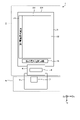
- FIG. 1 is a plan view of a display device having a detection device constituting the personal authentication system according to the embodiment.
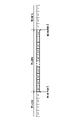
- FIG. 2 is a cross-sectional view taken along the line II-II'of FIG.
- FIG. 3A is a plan view showing a personal authentication system according to an embodiment.
- FIG. 3B is a plan view showing the personal authentication device according to the embodiment.
- FIG. 4A is a block diagram showing a configuration example of the personal authentication system according to the first embodiment.
- FIG. 4B is a block diagram showing a configuration example of the personal authentication device according to the first embodiment.
- FIG. 5 is an explanatory diagram for explaining the basic principle of touch detection of the mutual capacitance method.
- FIG. 6 is a plan view of the sensor substrate.
- FIG. 7 is an enlarged plan view showing a part of the first electrode and the second electrode.
- FIG. 8 is a cross-sectional view taken along the line VII-VII'of FIG.
- FIG. 9 is a timing chart showing an example of the switching operation between the first period and the second period.
- FIG. 10 is a diagram showing an example of the first detection mode.
- FIG. 11 is a diagram showing an example of the second detection mode.
- FIG. 12 is a diagram showing an example of the third detection mode.
- FIG. 13 is a diagram showing an example of the fourth detection mode.
- FIG. 14 is a diagram showing an example of a detection region in the personal authentication method according to the first embodiment.
- FIG. 15 is a diagram showing the positional relationship between the first region and the second region.
- FIG. 15 is a diagram showing the positional relationship between the first region and the second region.
- FIG. 16 is a diagram showing a fingerprint image after image composition in the first embodiment.
- FIG. 17A is a diagram illustrating an area for acquiring a divided image in the personal authentication method according to the first embodiment.
- FIG. 17B is a second diagram illustrating an area for acquiring a divided image in the personal authentication method according to the first embodiment.
- FIG. 17C is a third diagram illustrating an area for acquiring a divided image in the personal authentication method according to the first embodiment.
- FIG. 17D is a fourth diagram illustrating an area for acquiring a divided image in the personal authentication method according to the first embodiment.
- FIG. 18 is a flowchart showing an example of personal authentication data acquisition processing in the personal authentication system and the personal authentication device according to the first embodiment.
- FIG. 18 is a flowchart showing an example of personal authentication data acquisition processing in the personal authentication system and the personal authentication device according to the first embodiment.
- FIG. 19 is a flowchart showing an example of personal authentication processing in the personal authentication system and the personal authentication device according to the first embodiment.
- FIG. 20 is a sub-flow chart showing an example of password authentication processing in the personal authentication system and the personal authentication device according to the first embodiment.
- FIG. 21 is a sub-flow chart showing an example of fingerprint authentication processing in the personal authentication system and the personal authentication device according to the first embodiment.
- FIG. 22 is a sequence diagram showing a specific example of processing in the personal authentication system and the personal authentication device according to the first embodiment.
- FIG. 23A is a diagram illustrating an image acquisition area in the personal authentication method according to the modified example of the first embodiment.
- FIG. 23B is a second diagram illustrating an image acquisition area in the personal authentication method according to the modified example of the first embodiment.
- FIG. 23C is a third diagram illustrating an image acquisition area in the personal authentication method according to the modified example of the first embodiment.
- FIG. 23D is a fourth diagram illustrating an image acquisition area in the personal authentication method according to the modified example of the first embodiment.
- FIG. 24 is a diagram showing a fingerprint image after image composition in the second embodiment.
- FIG. 25A is a diagram illustrating an area for acquiring a divided image in the personal authentication method according to the second embodiment.
- FIG. 25B is a second diagram illustrating an area for acquiring a divided image in the personal authentication method according to the second embodiment.
- FIG. 25C is a third diagram illustrating an area for acquiring a divided image in the personal authentication method according to the second embodiment.
- FIG. 25A is a diagram illustrating an area for acquiring a divided image in the personal authentication method according to the second embodiment.
- FIG. 25B is a second diagram illustrating an area for acquiring a divided image in the personal authentication method according to the second embodiment.
- FIG. 25C is
- FIG. 25D is a fourth diagram illustrating an area for acquiring a divided image in the personal authentication method according to the second embodiment.
- FIG. 26A is a diagram illustrating an image acquisition area in the personal authentication method according to the modified example of the second embodiment.
- FIG. 26B is a second diagram illustrating an image acquisition area in the personal authentication method according to the modified example of the second embodiment.
- FIG. 26C is a third diagram illustrating an image acquisition area in the personal authentication method according to the modified example of the second embodiment.
- FIG. 26D is a fourth diagram illustrating an image acquisition area in the personal authentication method according to the modified example of the second embodiment.
- FIG. 1 is a plan view of a display device having a detection device constituting the personal authentication system according to the embodiment.
- FIG. 2 is a cross-sectional view taken along the line II-II'of FIG.
- the display device 100 of the present embodiment has a display area AA, a frame area GA, and a detection area FA.
- the display area AA is an area for displaying the image of the display panel 30.
- the frame area GA is an area outside the display area AA.
- the detection area FA is a region for detecting unevenness on the surface of a finger or the like that is in contact with or in close proximity to the detection area FA.
- the detection area FA is provided so as to overlap the entire surface of the display area AA.
- the display device 100 of the present embodiment includes a cover member 101, a detection device 2, and a display panel 30.
- the cover member 101 is a plate-shaped member having a first surface 101a and a second surface 101b opposite to the first surface 101a.
- the first surface 101a of the cover member 101 is the detection surface of the detection device 2, and when the detected body comes into contact with the detected surface, the plane coordinate position on the detected surface of the detected body and the detected object are detected. Unevenness on the surface of the body is detected.
- the object to be detected is the finger of the user, and the unevenness on the surface of the object to be detected includes a fingerprint.
- the first surface 101a of the cover member 101 is a display surface for displaying an image of the display panel 30, and is also an observation surface for the user to observe the image.
- the display panel 30 and the sensor unit 10 of the detection device 2 are provided on the second surface 101b side of the cover member 101.
- the cover member 101 is a member for protecting the sensor unit 10 and the display panel 30, and is provided so as to cover the sensor unit 10 and the display panel 30.
- the cover member 101 is, for example, a glass substrate or a resin substrate.
- the cover member 101, the sensor unit 10, and the display panel 30 are not limited to having a rectangular shape in a plan view, but have a circular shape, an oval shape, or an irregular shape in which a part of these external shapes is omitted. It may be a configuration. Further, for example, when the cover member 101 has a circular shape and the sensor unit 10 and the display panel 30 have a regular polygonal shape or the like, the external shapes of the cover member 101 and the sensor unit 10 and the display panel 30 are different. May be.
- As the cover member 101 not only a flat plate shape but also a curved surface display having a curved surface such that the display area AA is formed of a curved surface or the frame area GA is curved toward the display panel 30 can be adopted.
- the decorative layer 110 is provided on the second surface 101b of the cover member 101.
- the decorative layer 110 is a colored layer having a smaller light transmittance than the cover member 101.
- the decorative layer 110 can prevent the observer from seeing the wiring, the circuit, or the like superimposed on the frame region GA.
- the decorative layer 110 is provided on the second surface 101b, but may be provided on the first surface 101a.
- the decorative layer 110 is not limited to a single layer, and may have a configuration in which a plurality of layers are stacked.
- the detection device 2 includes a sensor unit 10 that detects surface irregularities such as a finger Fin that is in contact with or is close to the first surface 101a of the cover member 101.
- the sensor unit 10 of the detection device 2 is provided on the display panel 30. That is, the sensor unit 10 is provided between the cover member 101 and the display panel 30, and overlaps with the display panel 30 when viewed from a direction perpendicular to the first surface 101a.
- a flexible printed circuit board 76 is connected to the sensor unit 10, and a detection signal from the sensor unit 10 can be output to the outside.
- the adhesive layer 71 is, for example, an optical transparent resin (OCR: Optical Clear Resin or LOCA: Liquid Optically Clear Adhesive) which is a liquid UV curable resin.
- the adhesive layer 72 is, for example, an optical adhesive film (OCA: Optical Clear Adhesive).
- the display panel 30 has a first substrate 31, a second substrate 32, a polarizing plate 34 provided on the lower side of the first substrate 31, and a polarizing plate 35 provided on the upper side of the second substrate 32.
- a flexible printed circuit board 75 is connected to the first board 31.
- a liquid crystal display element is provided as a display functional layer between the first substrate 31 and the second substrate 32. That is, the display panel 30 is a liquid crystal panel.
- the display panel 30 is not limited to this, and may be, for example, an organic EL display panel (OLED: Organic Light Emitting Diode) or an inorganic EL display (micro LED, mini LED).
- the display panel may be a liquid crystal display panel (LCD: Liquid Crystal Display) using a liquid crystal element as a display element, or an electrophoresis type display panel (EPD: Electrophoretic Display) using an electrophoresis element as a display element. good.
- LCD Liquid Crystal Display
- EPD Electrophoretic Display
- the sensor unit 10 is arranged at a position closer to the cover member 101 than the display panel 30 in the direction perpendicular to the second surface 101b of the cover member 101. Therefore, for example, the distance between the detection electrode and the first surface 101a, which is the detection surface, can be reduced as compared with the case where the detection electrode for fingerprint detection is provided integrally with the display panel 30. Therefore, according to the display device 100 including the detection device 2 of the present embodiment, the detection performance can be improved.
- the display device 100 has a so-called out-cell configuration in which the sensor unit 10 and the display panel 30 are independent of each other, but the sensor unit 10 and a part of the display panel 30 or electrodes are also used. It may be an in-cell system or an on-cell system.
- FIG. 3A is a plan view showing a personal authentication system according to an embodiment.
- the personal authentication system 1 includes a detection device 2 and a control device 9.
- the detection device 2 includes a substrate 3 and a wiring board 4.
- the control device 9 has a control board 5.
- the control board 5 is electrically connected to the board 3 via the wiring board 4.
- the substrate 3 has the above-mentioned detection region AA and peripheral region GA.
- the sensor unit 10 is provided in the detection area AA.
- the first electrode selection circuit 15 and the detection electrode selection circuit 16 are provided in the peripheral region GA.
- the wiring board 4 is provided with a detection circuit 6.
- the detection circuit 6 is provided in, for example, a detection IC.
- a control circuit 7 is provided on the control board 5.
- the control circuit 7 is provided in, for example, a host IC composed of an FPGA (Field Programmable Gate Array).
- the control circuit 7 supplies a control signal to the sensor unit 10, the first electrode selection circuit 15, the detection electrode selection circuit 16, and the detection circuit 6 to control the detection operation of the sensor unit 10. It is also possible to adopt a configuration in which one or both of the first electrode selection circuit 15 and the detection electrode selection circuit 16 is provided in the detection circuit 6 or the control circuit 7.
- the first electrode selection circuit 15 is provided in a region extending along the second direction Dy in the peripheral region GA.
- the detection electrode selection circuit 16 is provided in a region extending along the first direction Dx in the peripheral region GA, and is provided between the sensor unit 10 and the detection circuit 6.
- the first direction Dx is one direction in a plane parallel to the substrate 3.
- the second direction Dy is one direction in a plane parallel to the substrate 3 and is a direction orthogonal to the first direction Dx.
- the second direction Dy may intersect with the first direction Dx without being orthogonal to each other.
- the third direction Dz is a direction orthogonal to the first direction Dx and the second direction Dy, and is a normal direction of the substrate 3.
- FIG. 3B is a plan view showing the personal authentication device according to the embodiment. As shown in FIG. 3B, the personal authentication device 1a corresponds to the detection device 2 of the personal authentication system 1 shown in FIG. 3A.
- the personal authentication circuit 8 is provided on the wiring board 4.
- the personal authentication circuit 8 is provided in, for example, a detection IC.
- control circuit 7a is provided on the control board 5 of the control device 9a.
- the detection circuit 6 of the personal authentication system 1 shown in FIG. 3A and the personal authentication circuit 8 of the personal authentication device 1a shown in FIG. 3B have different assigned functions.
- FIG. 4A is a block diagram showing a configuration example of the personal authentication system according to the first embodiment.
- the personal authentication system 1 includes a detection device 2 and a control device 9 as a host device of the detection device 2.
- the detection device 2 includes a sensor unit 10, a detection control unit 11, a first electrode selection circuit 15, a detection electrode selection circuit 16, and a detection circuit 6 including a detection unit 40.
- the control device 9 includes a control circuit 7 including a processing unit 50.
- FIG. 4B is a block diagram showing a configuration example of the personal authentication device according to the first embodiment.
- the personal authentication device 1a includes a sensor unit 10, a detection control unit 11, a first electrode selection circuit 15, a detection electrode selection circuit 16, a detection unit 40, and a processing unit 50.
- the authentication circuit 8 and the like are included. That is, in the personal authentication device 1a shown in FIGS. 3B and 4B, the personal authentication circuit 8 has the function of the processing unit 50 of the control circuit 7 of the personal authentication system 1 shown in FIGS. 3A and 4A.
- Each component in the following description is applicable to any of the personal authentication system 1 shown in FIGS. 3A and 4A, and the personal authentication device 1a shown in FIGS. 3B and 4B.
- the sensor unit 10 performs detection according to the second drive signal Vtx2 supplied from the first electrode selection circuit 15. That is, a plurality of first electrodes Tx (see FIG. 6) are individually or simultaneously selected by the operation of the first electrode selection circuit 15. Then, the first electrode selection circuit 15 supplies the second drive signal Vtx2 whose phase is determined based on a predetermined code to each of the selected plurality of first electrodes Tx. Based on the detection principle of the mutual capacitance method, the sensor unit 10 converts the change in the unevenness of the surface of the finger Fin or the hand close to or in contact with the change of the electric signal and outputs it to the detection circuit 6.
- the sensor unit 10 can also detect the position (coordinates) of a finger Fin or the like that is in contact with or is close to the sensor unit 10 according to the first drive signal Vtx1 supplied from the first electrode selection circuit 15.
- the sensor unit 10 scans the first electrode Tx for each first electrode block containing the plurality of first electrode Tx or at a ratio of one for each of the plurality of first electrodes Tx, and detects the entire detection region FA.
- the sensor unit 10 outputs to the detection circuit 6 a change in the electric signal due to the presence or absence of a finger Fin in contact with the detection surface, based on the detection principle of the mutual capacitance method.
- the touch detection of the detection surface by the first drive signal Vtx1 requires only the coordinates of the finger to be detected and specified, so that the detection resolution is lower than the detection by the second drive signal Vtx2.
- the detection control unit 11 is a circuit that supplies control signals to the first electrode selection circuit 15, the detection electrode selection circuit 16, and the detection unit 40, respectively, and controls their operations.
- the detection control unit 11 includes a drive unit 11a and a clock signal output unit 11b.
- the drive unit 11a supplies the power supply voltage VP to the first electrode selection circuit 15.
- the detection control unit 11 supplies various control signals Vctrl to the first electrode selection circuit 15 based on the clock signal of the clock signal output unit 11b.
- the first electrode selection circuit 15 is a circuit that simultaneously or individually selects a plurality of first electrode Tx based on various control signals Vctrl.
- the first electrode selection circuit 15 supplies a first drive signal Vtx1 or a second drive signal Vtx2 to a plurality of selected first electrodes Tx based on various control signals Vctrl and one or a plurality of power supply voltage VPs.
- the first drive signal Vtx1 and the second drive signal Vtx2 have different waveforms themselves including wavelengths and amplitudes, and also include those having the same waveform but different periods of output to the sensor unit 10.
- the sensor unit 10 makes the selection state of the first electrode Tx different by the first electrode selection circuit 15, so that the first detection mode M1, the second detection mode M2, the third detection mode M3, and the fourth detection mode M4 ( (See FIGS. 10 to 13) can be realized.
- the detection electrode selection circuit 16 is a switch circuit that simultaneously selects a plurality of second electrodes Rx (see FIG. 6).
- the detection electrode selection circuit 16 selects a plurality of second electrodes Rx based on the second electrode selection signal Vhsel supplied from the detection control unit 11, and connects the plurality of second electrodes Rx to the detection circuit 6. ..
- the detection unit 40 is a finger on the detection surface at a relatively large pitch based on the control signal supplied from the detection control unit 11 and the first detection signal Vdet1 and the second detection signal Vdet2 supplied from the sensor unit 10. It is a circuit that detects the presence or absence of a touch and detects the fingerprint of the finger at a relatively fine pitch. Each component of the detection unit 40 operates synchronously based on the control signal supplied from the detection control unit 11.
- the detection unit 40 includes a detection signal amplification unit 42, an A / D conversion unit 43, a signal processing unit 44, a coordinate extraction unit 45, a fingerprint detection area setting unit 46, and a divided image generation unit 47 as each component unit. And a detection timing control unit 48. When it is not necessary to distinguish between the first detection signal Vdet1 and the second detection signal Vdet2 in the following description, it is simply referred to as a detection signal Vdet.
- the detection timing control unit 48 includes a detection signal amplification unit 42, an A / D conversion unit 43, a signal processing unit 44, a coordinate extraction unit 45, and a divided image based on the control signal supplied from the detection control unit 11.
- the generation unit 47 and the generation unit 47 are controlled to operate in synchronization with each other.
- the detection signal amplification unit 42 amplifies the detection signal Vdet.
- the A / D conversion unit 43 converts the analog signal output from the detection signal amplification unit 42 into a digital signal.
- the signal processing unit 44 performs a predetermined decoding process based on the output signal of the A / D conversion unit 43. Specifically, the signal processing unit 44 performs a process of extracting a signal (absolute value
- the coordinate extraction unit 45 extracts the coordinates of the object to be detected (hereinafter, also referred to as “touch detection coordinates”) in contact with or close to the sensor unit 10 based on the decoding processing result of the signal processing unit 44, and causes the processing unit 50 to extract the coordinates. Output.
- the fingerprint detection area setting unit 46 sets an area for detection from the detection start coordinates output from the processing unit 50.
- the detection start coordinates and the detection area will be described later.
- the divided image generation unit 47 generates a divided image by extracting the unevenness of the surface of the detected object based on the decoding processing result of the signal processing unit 44. Although the divided image will be described later, the present disclosure is not limited by the method for generating the divided image.
- the personal authentication system 1 shown in FIG. 4A and the personal authentication device 1a shown in FIG. 4B detect a finger Fin in contact with the detection surface of the sensor unit 10 based on the capacitance type detection principle ( Hereinafter referred to as "touch detection”). Further, the personal authentication system 1 and the personal authentication device 1a detect fingerprints by detecting the unevenness of the surface of the finger Fin in contact with the sensor unit 10 based on the capacitance type detection principle (hereinafter,). Called “fingerprint detection").
- touch state the state in which the capacitance is changed by the contact of the finger Fin.
- non-touch state a state in which the capacity is not changed by the finger Fin.
- FIG. 5 is an explanatory diagram for explaining the basic principle of touch detection of the mutual capacitance method. Note that FIG. 5 also shows a detection circuit.
- the capacitive element C1 includes a pair of electrodes, a drive electrode E1 and a detection electrode E2 that are arranged so as to face each other with the dielectric D interposed therebetween.
- an electric field (not shown) formed between the facing surfaces of the drive electrode E1 and the detection electrode E2
- an electric field extending from the end of the drive electrode E1 toward the upper surface of the detection electrode E2 is generated. ..
- One end of the capacitive element C1 is connected to an AC signal source (drive signal source), and the other end is connected to the voltage detector DET.
- the voltage detector DET is, for example, an integrating circuit included in the detection unit 40 shown in FIG.
- An AC rectangular wave Sg having a predetermined frequency (for example, about several kHz to several hundred kHz) is applied from the AC signal source to the drive electrode E1 (one end of the capacitive element C1).
- a current corresponding to the capacitance value of the capacitance element C1 flows through the voltage detector DET.
- the voltage detector DET converts the fluctuation of the current corresponding to the AC square wave Sg into the fluctuation of the voltage.
- the capacitive element C1 gradually acts as a capacitive element having a smaller capacitive value in response to the approach than the capacitive value in the non-contact state.
- the amplitude of the voltage signal output from the voltage detector DET becomes smaller as the finger Fin approaches the contact state as compared with the non-contact state.
- of this voltage difference changes according to the influence of the finger Fin in contact with the detection surface.
- the detection unit 40 determines whether the finger Fin is in contact with or not in contact with the detection surface by comparing the absolute value
- the detection unit 40 determines the unevenness of the finger Fin based on the absolute value
- the fingerprint image is data as surface information formed based on outputs from a plurality of second electrodes Rx, and is a touch that specifies one or several coordinate positions on the detection surface. It is different from the coordinates (point information). More specifically, the fingerprint image is a collection of detection data in a plurality of detection unit regions, and each detection data includes, for example, the coordinates of the detection unit region and the determination result of unevenness at each coordinate position. As for the judgment of the unevenness, it is possible to adopt a binary judgment result such that the detection result is judged to be concave when the detection result is larger than the threshold value and the detection result is judged to be convex when the detection result is larger than the threshold value as described above. can.
- the actual detection signal may be more finely digitized data based on a plurality of threshold values.
- the data may be provided with the magnitude of the output signal at each coordinate as RAW data as it is. By accumulating the data for each of these coordinates, surface information with a two-dimensional spread is formed.
- the present embodiment targets the finger Fin as the detected body and its fingerprint, it goes without saying that the detected body is not limited to the finger and the unevenness of the detected body is not limited to the fingerprint.
- FIG. 6 is a plan view of the sensor substrate.
- FIG. 7 is an enlarged plan view showing a part of the first electrode and the second electrode.
- FIG. 8 is a cross-sectional view taken along the line VII-VII'of FIG.
- the sensor substrate 21 is a glass substrate having a translucency capable of transmitting visible light.
- the sensor substrate 21 may be a translucent resin substrate or a resin film made of a resin such as polyimide.
- the sensor unit 10 is a translucent sensor.
- the first electrode Tx extends in the first direction Dx, and a plurality of the first electrodes Tx are arranged in the second direction Dy.
- the second electrode Rx extends in the second direction Dy, and a plurality of the second electrodes Rx are arranged in the first direction Dx.
- the second electrode Rx extends in a direction intersecting the first electrode Tx in a plan view.
- Each second electrode Rx is connected to a flexible printed circuit board 76 provided on the short side of the frame region GA of the sensor substrate 21 via a frame wiring (not shown).
- the first electrode Tx and the second electrode Rx are provided in the detection region FA.
- the first electrode Tx is made of a translucent conductive material such as ITO (Indium Tin Oxide).
- the second electrode Rx is made of a metal material such as aluminum or an aluminum alloy.
- the first electrode Tx may be made of a metal material, and the second electrode Rx may be made of ITO. However, by using the second electrode Rx as a metal material, the resistance related to the detection signal Vdet can be reduced.
- the first direction Dx is one direction in a plane parallel to the sensor substrate 21, for example, a direction parallel to one side of the detection region FA.
- the second direction Dy is one direction in a plane parallel to the sensor substrate 21 and is a direction orthogonal to the first direction Dx.
- the second direction Dy may intersect with the first direction Dx without being orthogonal to each other.
- plane view refers to a case of being viewed from a direction perpendicular to the sensor substrate 21.
- Capacitance is formed at the intersection of the second electrode Rx and the first electrode Tx.
- the first electrode selection circuit 15 selects the first electrode Tx, and at the same time, the first drive signal Vtx1 or the first drive signal Vtx1 or the first is sent to the selected first electrode Tx. 2 Drive signal Vtx2 is supplied.
- fingerprint detection is performed by outputting a detection signal Vdet corresponding to a capacitance change due to surface irregularities of a finger or the like that is in contact with or adjacent to the second electrode Rx.
- touch detection is performed by outputting a detection signal Vdet corresponding to a change in capacitance due to contact or a nearby finger or the like from the second electrode Rx.
- the first electrode selection circuit 15 includes a first selection circuit 151, a second selection circuit 152, a third selection circuit 153, and a first electrode block selection circuit 154.
- first selection circuit 151, the second selection circuit 152, the third selection circuit 153, and the first electrode block selection circuit 154 are not limited to the configurations provided as individual circuits.
- the first electrode selection circuit 15 may be provided as one integrated circuit including the functions of the first selection circuit 151, the second selection circuit 152, the third selection circuit 153, and the first electrode block selection circuit 154.
- the first electrode selection circuit 15 may be a semiconductor integrated circuit (IC).
- the second electrode Rx is a zigzag-shaped line and has a longitudinal axis in the second direction Dy as a whole.
- the second electrode Rx has a plurality of first straight line portions 26a, a plurality of second straight line portions 26b, and a plurality of bending portions 26x.
- the second straight line portion 26b extends in a direction intersecting with the first straight line portion 26a.
- the bent portion 26x connects the first straight line portion 26a and the second straight line portion 26b.
- the first straight line portion 26a extends in a direction intersecting the first direction Dx and the second direction Dy.
- the second straight line portion 26b also extends in a direction intersecting the first direction Dx and the second direction Dy.
- the first straight line portion 26a and the second straight line portion 26b are arranged so as to be symmetrical with respect to a virtual line (not shown) parallel to the first direction Dx.
- the first straight line portion 26a and the second straight line portion 26b are alternately connected in the second direction Dy.
- the arrangement interval of the bent portion 26x in the second direction Dy is set to Pry. Further, the arrangement interval of the bent portions 26x in the first direction Dx between the adjacent second electrodes Rx is defined as Prx. In this embodiment, for example, Prx ⁇ Pry is preferable.
- the second electrode Rx is not limited to the zigzag shape, and may have other shapes such as a wavy line shape and a linear shape.
- the plurality of first electrodes Tx-1, Tx-2, Tx-3, Tx-4 ... Have a plurality of electrode portions 23a, 23b and a plurality of connection portions 24, respectively.
- the first electrode Tx when it is not necessary to distinguish and explain the first electrode Tx-1, Tx-2, Tx-3, Tx-4 ..., it is simply referred to as the first electrode Tx.
- the first electrodes Tx-1 and Tx-2 intersecting the second straight line portion 26b of the second electrode Rx include an electrode portion 23a having two sides parallel to the second straight line portion 26b.
- the first electrodes Tx-3 and Tx-4 intersecting the first straight line portion 26a of the second electrode Rx include an electrode portion 23b having two sides parallel to the first straight line portion 26a.
- a plurality of electrode portions 23a and 23b are arranged along the second electrode Rx. As a result, the separation distance between the zigzag-shaped second electrode Rx and the electrode portions 23a and 23b can be made constant in a plan view.
- the plurality of electrode portions 23a are arranged in the first direction Dx and are arranged apart from each other. Further, in each of the plurality of first electrodes Tx, the connecting portion 24 connects the adjacent electrode portions 23a among the plurality of electrode portions 23a. Further, in a plan view, each of the plurality of second electrodes Rx passes between the adjacent electrode portions 23a and intersects with the connecting portion 24.
- the first electrodes Tx-3 and Tx-4 have the same configuration.
- the second electrode Rx is a thin metal wire, and the width of the first direction Dx of the second electrode Rx is smaller than the width of the first direction Dx of the electrode portions 23a and 23b. With such a configuration, the area where the first electrode Tx and the second electrode Rx overlap is reduced, and the parasitic capacitance can be suppressed.
- the arrangement interval of the first electrode Tx in the second direction Dy is Pt.
- the arrangement interval Pt is about 1 ⁇ 2 of the arrangement interval Pry of the bent portion 26x of the second electrode Rx.
- the arrangement interval Pt is not limited to this, and may be other than a half-integer multiple of the arrangement interval Pry.
- the arrangement interval Pt is, for example, 50 ⁇ m or more and 100 ⁇ m or less.
- the connecting portions 24 adjacent to the first direction Dx have an arrangement interval Pb in the second direction Dy and are arranged alternately.
- the electrode portions 23a and 23b have parallel four-sided shapes, respectively, but may have other shapes.
- the electrode portions 23a and 23b may have a rectangular shape, a polygonal shape, or an irregular shape.
- the cross section of the frame region GA is a cross section obtained by cutting a portion including the thin film transistor Tr included in the first electrode selection circuit 15.
- FIG. 8 in order to show the relationship between the layer structure of the detection region FA and the layer structure of the frame region GA, a cross section of the detection region FA along the VII-VII'line and a cross section of the portion of the frame region GA including the thin film transistor Tr are shown. And are shown schematically connected.
- a thin film transistor Tr is provided in the frame region GA on the sensor substrate 21.
- the thin film transistor Tr includes a semiconductor layer 61, a source electrode 62, a drain electrode 63, and a gate electrode 64.
- the gate electrode 64 is provided on the sensor substrate 21.
- the first interlayer insulating film 81 is provided on the sensor substrate 21 and covers the gate electrode 64.
- As the material of the gate electrode 64 aluminum (Al), copper (Cu), silver (Ag), molybdenum (Mo) or an alloy thereof is used.
- the first interlayer insulating film 81 is not limited to a single layer, and may be a film having a laminated structure.
- the first interlayer insulating film 81 may be a film having a laminated structure in which a silicon nitride film is formed on a silicon oxide film.
- the semiconductor layer 61 is provided on the first interlayer insulating film 81.
- the second interlayer insulating film 82 is provided on the first interlayer insulating film 81 and covers the semiconductor layer 61.
- the semiconductor layer 61 is exposed at the bottom of the contact hole provided in the second interlayer insulating film 82.
- As the material of the semiconductor layer 61 polysilicon or an oxide semiconductor is used.
- As the material of the second interlayer insulating film 82 a silicon oxide film, a silicon nitride film, or a silicon oxide nitride film is used.
- the second interlayer insulating film 82 is not limited to a single layer, and may be a film having a laminated structure.
- the second interlayer insulating film 82 may be a film having a laminated structure in which a silicon nitride film is formed on a silicon oxide film.
- the source electrode 62 and the drain electrode 63 are provided on the second interlayer insulating film 82.
- the source electrode 62 and the drain electrode 63 are connected to the semiconductor layer 61 via contact holes provided in the second interlayer insulating film 82, respectively.
- titanium aluminum (TiAl) which is an alloy of titanium and aluminum, is used.
- an insulating resin layer 27, an electrode portion 23b of the first electrode Tx, and a connecting portion 24 are provided on the second interlayer insulating film 82.
- the resin layer 27 provided in the frame region GA covers the source electrode 62 and the drain electrode 63. Further, the drain electrode 63 is electrically connected to the first electrode Tx via a contact hole provided in the resin layer 27 provided in the frame region GA.
- the resin layer 27 provided in the detection region FA has a first resin layer 27A and a second resin layer 27B that is thinner than the first resin layer 27A.
- the first resin layer 27A covers a portion of the connecting portion 24 located directly below the second electrode Rx.
- the second resin layer 27B provided in the detection region FA covers a portion of the connecting portion 24 located directly below the electrode portion 23b.
- Contact holes H1 and H2 are provided in the second resin layer 27B.
- the peripheral edge portion of the electrode portion 23b is connected to the connection portion 24 via the contact holes H1 and H2.
- the electrode portion 23b is in contact with the second interlayer insulating film 82.
- the second electrode Rx is provided on the first resin layer 27A.
- the second electrode Rx has, for example, a first metal layer 141, a second metal layer 142, and a third metal layer 143.
- the second metal layer 142 is provided on the third metal layer 143, and the first metal layer 141 is provided on the second metal layer 142.
- molybdenum or a molybdenum alloy is used as the material of the first metal layer 141 and the third metal layer 143.
- Aluminum or an aluminum alloy is used as the material of the second metal layer 142.
- the molybdenum or molybdenum alloy constituting the first metal layer 141 has a lower visible light reflectance than the aluminum or aluminum alloy constituting the second metal layer 142. This makes it possible to make the second electrode Rx invisible.
- An insulating film 83 is provided on the resin layer 27, the electrode portion 23b, and the second electrode Rx. The upper surface and the side surface of the second electrode Rx are covered with the insulating film 83.
- a film having a high refractive index and a low reflectance such as a silicon nitride film, is used.
- the first electrode Tx and the second electrode Rx are formed on the same sensor substrate 21.
- the first electrode Tx and the second electrode Rx are provided in different layers via the resin layer 27 which is an insulating layer.
- the personal authentication data acquisition period in the personal authentication system 1 and the personal authentication device 1a is a first period in which a touch detection period (coordinate detection period) for executing touch detection is provided, and a fingerprint detection for performing fingerprint detection. It has a second period with a period (plane information detection period).
- FIG. 9 is a timing chart showing an example of the switching operation between the first period and the second period.
- TP indicates a touch detection period (coordinate detection period)
- FP indicates a fingerprint detection period (plane information detection period).
- the personal authentication system 1 and the personal authentication device 1a according to the present embodiment shift from the first period to the second period based on the first control signal output from the processing unit 50. Further, the personal authentication system 1 and the personal authentication device 1a according to the present embodiment shift from the second period to the first period based on the second control signal output from the processing unit 50.
- FIG. 10 is a diagram showing an example of the first detection mode.
- FIG. 11 is a diagram showing an example of the second detection mode.
- FIG. 12 is a diagram showing an example of the third detection mode.
- the personal authentication system 1 and the personal authentication device 1a have a first detection pitch Pts larger than that of the second detection mode M2 (see FIG. 11), and the detection region FA.
- the first electrode selection circuit 15 bundles a plurality of first electrodes Tx adjacent to each other or arranged at a predetermined pitch to form a first electrode block, and first drives each of the first electrode blocks.
- the signal Vtx1 is supplied.
- the same first drive signal Vtx1 is supplied to the plurality of first electrodes Tx included in each first electrode block.
- the detection electrode selection circuit 16 bundles a plurality of second electrodes Rx adjacent to each other or arranged at a predetermined pitch to form a second electrode block, and each second electrode block is second.
- the drive signal Vtx2 may be supplied. Further, all the second electrodes Rx may be connected to the detection unit 40, respectively.
- the personal authentication system 1 and the personal authentication device 1a have a second detection pitch Pf smaller than that of the first detection mode M1 (see FIG. 10), and the detection region FA.
- the first electrode selection circuit 15 supplies the second drive signal Vtx2 whose phase is determined based on a predetermined code to each of the plurality of first electrodes Tx.
- the first electrode selection circuit 15 can also adopt a configuration in which each first electrode Tx is individually scanned and a pulse wave as a second drive signal Vtx2 is supplied along with the scanning.
- the supply of the second drive signal Vtx2 includes any of these aspects.
- the personal authentication system 1 and the personal authentication device 1a can perform detection at a second detection pitch Pf smaller than that of the first detection mode M1. More specifically, even if the finger is in contact with the detection surface when viewed from a macro perspective, a part of the finger is detected due to the unevenness of the finger surface when viewed from a micro perspective. It comes into contact with the surface, and a part of it is slightly separated from the detection surface.
- the unevenness of the surface of the object to be detected (here, the unevenness of the surface of the finger, that is, the fingerprint) when viewed from the microscopic point of view is detected.
- the second detection pitch may be smaller than the first detection pitch, and the smallest second detection pitch is two adjacent first electrodes or two adjacent detection electrodes intersecting them. Is the pitch formed by.
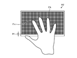
- the personal authentication system 1 and the personal authentication device 1a perform detection on the entire surface of the detection area FA. Therefore, the personal authentication system 1 and the personal authentication device 1a are not limited to fingerprint detection only, and can detect, for example, a palm print. Alternatively, the personal authentication system 1 and the personal authentication device 1a can detect the shape of the hand in contact with or close to the detection area FA and specify the position of the fingertip. In this case, the fingerprint can be detected by performing signal processing or arithmetic processing only in the area where the fingertips are in contact with or close to each other.
- the area where fingerprint detection is performed on the detection surface may be a part of the detection surface.
- the personal authentication system 1 and the personal authentication device 1a perform detection at the second detection pitch Pf in the first partial region FA1 of a part of the detection region FA.
- the first electrode selection circuit 15 supplies the second drive signal Vtx2 only to the plurality of first electrodes Tx included in the first partial region FA1. Even in the third detection mode M3, the personal authentication system 1 and the personal authentication device 1a can perform detection at the second detection pitch Pf.
- the time required for the detection can be shortened, and the processing performed by the detection unit 40 (see FIGS. 4A and 4B) can be reduced.
- the first partial region FA1 is a preset fixed region. However, the position and size of the first partial region FA1 may be changed as appropriate.
- the fingerprint detection may be executed in the third detection mode M3. Specifically, in the first period, touch detection is executed by the first detection mode M1, and in the second period, fingerprint detection is executed by the third detection mode M3. As a result, the fingerprint detection period FP can be shortened, and the time required for detection can be shortened.
- FIG. 13 is a diagram showing an example of the fourth detection mode.
- the personal authentication system 1 and the personal authentication device 1a execute the touch detection of the first detection mode M1 in the first period, and detect whether or not the finger is in contact with the detection surface.
- the personal authentication system 1 and the personal authentication device 1a shift to the second period and execute fingerprint detection in the fourth detection mode M4.
- the personal authentication system 1 and the personal authentication device 1a detect at the second detection pitch Pf only in the second partial region FA2 which is a predetermined region including the position where the finger Fin or the like is detected. conduct.
- the position and size of the second partial region FA2 can be changed based on the information such as the finger Fin detected in the touch detection period TP.
- fingerprint detection in the fourth detection mode M4 may be performed based on the detection result in the first detection mode M1.
- the area of the second partial region FA2 can be reduced, so that the time required for fingerprint detection can be significantly shortened as compared with the case where the fingerprint is detected over the entire detection region.
- the personal authentication method of this disclosure will be described below.
- the personal authentication method in the personal authentication system 1 and the personal authentication device 1a is not limited to the personal authentication methods shown below.
- FIG. 14 is a diagram showing an example of a detection area in the personal authentication method according to the first embodiment.
- a plurality of first area KYs to which different input keys are assigned are provided in the detection area FA.
- the input key is not limited to numbers, and may include, for example, uppercase or lowercase alphabets or symbols such as "#" and "*".
- touch detection is performed by the second detection mode M2 described above, and the key input by the user is identified.
- the input key "5" is input. Identify as being done.
- the coordinates on the detection area FA touched by the user are any of the first area KY “0", “1", “2”, ..., "9".
- a predetermined area having these coordinates as the center coordinate C is defined as a second area FG, and the second area FG is used as an area for acquiring a fingerprint image.
- FIG. 15 is a diagram showing the positional relationship between the first region and the second region.
- FIG. 15 shows an example in which the coordinates identified as the input key “5” in the password input for personal authentication are set as the center coordinates C (Cx, Cy) of the second region FG. That is, the user touches the detection surface to touch the input key "5", but touches a position slightly deviated from the center position of the input key "5", and performs arithmetic processing on the touch via the detection unit and the processing unit. As a result, the center position touched by the user is recognized as the center coordinate C (Cx, Cy). Then, the second region FG for fingerprint detection is determined in relation to the center coordinate C.
- each time each key of the password is input an image of an area smaller than the second area FG shown in FIG. 15 is acquired.
- the detection area to be detected during the time when the touched state of each input key is maintained when the password is input and the image acquired as a result can be made as small as possible. Therefore, it is possible to improve the accuracy of the image acquired for each key input of the password.
- the image acquired for each password key input is combined to generate a fingerprint image for personal authentication. This makes it possible to acquire a highly accurate fingerprint image.
- the scanning direction in touch detection and fingerprint detection is the direction along the second direction Dy.
- FIG. 16 is a diagram showing a fingerprint image after image composition in the first embodiment.
- the divided regions SF1, SF2, SF3, and SF4 for acquiring each divided image are assigned so as to be relatively aligned in the fingerprint scanning direction. The example given is shown.
- the number of divisions of the second region FG that is, the number of division region SFs is not limited to four.
- the number of divisions of the second area FG depends on the number of digits of the password. For example, as shown in FIG. 16, when allocating four divided areas SF1, SF2, SF3, SF4 corresponding to the second area FG, the number of digits of the password needs to be 4 or more. In other words, the number of divisions of the second area FG needs to be equal to or less than the number of digits of the password.
- the processing unit 50 includes a touch determination unit 51, a detection start coordinate setting unit 52, a divided image receiving unit 53, a first storage unit 54, a fingerprint image generation unit 55, and a second.
- a personal authentication result storage unit 515 may be, for example, a RAM (Random).
- first storage unit 54, the second storage unit 56, the third storage unit 57, the fingerprint authentication result storage unit 59, the password storage unit 511, the password authentication result storage unit 513, and the personal authentication result storage unit 515 are one. It may be a RAM, a ROM, a register circuit, or the like.
- the touch determination unit 51 determines whether or not the touch state is valid in the personal authentication method of the present disclosure, based on the touch detection coordinates output from the detection unit 40 in the first period described above.
- the "effective touch state in the personal authentication method of the present disclosure” means that the coordinates on the detection area FA touched by the user, that is, the touch detection coordinates output from the detection unit 40 are shown in FIG. It is shown that the coordinates are in the first region KY shown in. Specifically, when the touch determination unit 51 determines that the touch state is in the coordinates in the first region KY shown in FIG. 14, the touch determination unit 51 transmits a first control signal for shifting to the second period to the detection control unit 11. Output.
- the above-mentioned "effective touch state in the personal authentication method of the present disclosure” is referred to as "key input”.
- the touch determination unit 51 detects that the key has been input, the touch determination unit 51 outputs a first control signal for shifting to the second period to the detection control unit 11.
- the touch determination unit 51 sequentially stores the key input key (“5” in the example shown in FIG. 15) in the password storage unit 511.
- the touch determination unit 51 issues a password authentication start command to the password authentication unit 512 in the subsequent stage. Output.
- the detection start coordinate setting unit 52 uses the key-input touch detection coordinates to determine the fingerprint detection start coordinates (hereinafter, simply referred to as “detection start coordinates”). To set.
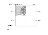
- FIG. 17A is a diagram illustrating an area for acquiring a divided image in the personal authentication method according to the first embodiment.
- FIG. 17B is a second diagram illustrating an area for acquiring a divided image in the personal authentication method according to the first embodiment.
- FIG. 17C is a third diagram illustrating an area for acquiring a divided image in the personal authentication method according to the first embodiment.
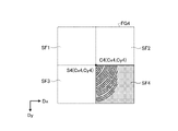
- FIG. 17D is a fourth diagram illustrating an area for acquiring a divided image in the personal authentication method according to the first embodiment.
- FIG. 17A shows an example of allocating the divided area SF1 for acquiring the divided image in the second area FG1 at the time of key input of the first digit of the password.
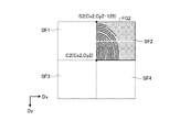
- FIG. 17B shows an example of allocating the divided area SF2 for acquiring the divided image in the second area FG2 at the time of key input of the second digit of the password.
- FIG. 17C shows an example of allocating the divided area SF3 for acquiring the divided image in the second area FG3 at the time of key input of the third digit of the password.
- FIG. 17D shows an example of allocating the divided area SF4 for acquiring the divided image in the second area FG4 at the time of key input of the fourth digit of the password.
- the divided regions SF1, SF2, SF3, and SF4 are relatively fingerprints in the second region FG1, FG2, FG3, and FG4 when each divided image is acquired.
- An example is shown in which they are assigned to line up in the scanning direction.
- the size of the second region FG is 256 ⁇ 256 in the first direction Dx and 256 in the second direction Dy.
- the detection start coordinate setting unit 52 first inputs the first digit of the password to the center coordinates C1 of the second region FG1 as shown in FIG. 17A.
- the detection start coordinates S1 (Cx1-128, Cy1-128) are set for (Cx1, Cy1).
- the fingerprint detection area setting unit 46 of the detection unit 40 has a size of 256 ⁇ 64 starting from the detection start coordinates S1 (Cx1-128, Cy1-128) shown in FIG. 17A as the fingerprint detection area for acquiring the divided image. Allocate the division area SF1 of.
- the detection start coordinate setting unit 52 performs a key input of the second digit of the password, as shown in FIG. 17B, at the center coordinates C2 of the second region FG2.
- the detection start coordinates S2 (Cx2-128, Cy2-128 + 64) are set for (Cx2, Cy2).
- the center coordinate of the second digit of the password is shown as the center coordinate C2 (Cx2, Cy2).
- the fingerprint detection area setting unit 46 of the detection unit 40 has a size of 256 ⁇ 64 starting from the detection start coordinates S2 (Cx2-128, Cy2-128 + 64) shown in FIG. 17B as the fingerprint detection area for acquiring the divided image. Allocate the division area SF2 of. That is, when the detection area of 256 ⁇ 256 defined based on the center coordinates of the finger is divided into four in the second direction Dy, the detection area (divided area SF2) in the second stage from the top is assigned.
- the detection start coordinate setting unit 52 performs the key input of the third digit of the password, as shown in FIG. 17C, at the center coordinates C3 of the second region FG3.
- the detection start coordinates S3 (Cx3-128, Cy3-128 + 64 ⁇ 2) are set for (Cx3, Cy3).
- the center coordinate of the third digit of the password is shown as the center coordinate C3 (Cx3, Cy3).
- the fingerprint detection area setting unit 46 of the detection unit 40 has 256 ⁇ starting from the detection start coordinates S3 (Cx3-128, Cy3-128 + 64 ⁇ 2) shown in FIG. 17C as the fingerprint detection area for acquiring the divided image. Allocate a division area SF3 of 64 size. That is, when the detection area of 256 ⁇ 256 defined based on the center coordinates of the finger is divided into four in the second direction Dy, the detection area (divided area SF3) in the third stage from the top is assigned.
- the detection start coordinate setting unit 52 performs a key input of the fourth digit of the password, as shown in FIG. 17D, at the center coordinates C4 of the second region FG4.
- the detection start coordinates S4 (Cx4-128, Cy4-128 + 64 ⁇ 3) are set for (Cx4, Cy4).
- the center coordinate of the fourth digit of the password is shown as the center coordinate C4 (Cx4, Cy4).
- the fingerprint detection area setting unit 46 of the detection unit 40 has 256 ⁇ starting from the detection start coordinates S4 (Cx4-128, Cy4-128 + 64 ⁇ 3) shown in FIG. 17D as the fingerprint detection area for acquiring the divided image. Allocate a division area SF4 of 64 size. That is, when the detection area of 256 ⁇ 256 defined based on the center coordinates of the finger is divided into four in the second direction Dy, the detection area (divided area SF4) in the fourth stage from the top is assigned.
- the divided image receiving unit 53 receives the divided image output from the detection unit 40 in the second period described above, and stores the divided image as buffering data in the first storage unit 54. ..
- the fingerprint image generation unit 55 reads out the divided image stored as buffering data in the first storage unit 54, and sequentially stores it as buffering data in the second storage unit 56. At this time, the fingerprint image generation unit 55 outputs a second control signal for shifting to the first period to the detection control unit 11.
- the accumulated number m of the divided images stored in the second storage unit 56 is a predetermined number M (in the example shown in FIG. 16, the divided images in the four divided areas SF1, SF2, SF3, SF4).
- M the number M
- the divided images stored in the second storage unit 56 are combined to generate a fingerprint image for personal authentication, and the generated fingerprint image for personal authentication is stored in the third storage unit 57.
- a fingerprint authentication start command is output to the fingerprint authentication unit 58 in the subsequent stage.
- the fingerprint authentication unit 58 performs authentication determination processing of the fingerprint image for personal authentication stored in the third storage unit 57 based on the fingerprint authentication start command from the fingerprint image generation unit 55, and fingerprints the fingerprint authentication determination result. It is stored in the result storage unit 59.
- the present disclosure is not limited by this authentication determination method. For example, the fingerprint image for collation acquired in advance is collated with the fingerprint image for personal authentication stored in the third storage unit 57, and if the predetermined feature points match, the authentication is successful. Is also good.
- the password authentication unit 512 synthesizes the keys stored in the password storage unit 511 to generate a password for personal authentication based on the password authentication start command from the touch determination unit 51, and determines the authentication of the password for personal authentication. Processing is performed, and the password authentication determination result is stored in the password authentication result storage unit 513. Specifically, for example, the preset password for verification and the generated password for personal authentication are collated, and if they match, the authentication is successful.
- the personal authentication unit 514 refers to the password authentication determination result stored in the password authentication result storage unit 513 and the fingerprint authentication determination result stored in the fingerprint authentication result storage unit 59, performs personal authentication determination processing, and performs the individual authentication determination process.
- the authentication processing result is stored in the personal authentication result storage unit 515. Specifically, the personal authentication unit 514 assumes that the personal authentication is successful when the password authentication determination result is the authentication success and the fingerprint authentication determination result is the authentication success.
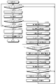
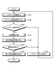
- FIG. 18 is a flowchart showing an example of personal authentication data acquisition processing in the personal authentication system and the personal authentication device according to the first embodiment.
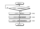
- FIG. 19 is a flowchart showing an example of personal authentication processing in the personal authentication system and the personal authentication device according to the first embodiment.
- FIG. 20 is a sub-flow chart showing an example of password authentication processing in the personal authentication system and the personal authentication device according to the first embodiment.
- FIG. 21 is a sub-flow chart showing an example of fingerprint authentication processing in the personal authentication system and the personal authentication device according to the first embodiment.
- FIG. 22 is a sequence diagram showing a specific example of processing in the personal authentication system and the personal authentication device according to the first embodiment.
- the touch determination unit 51 of the processing unit 50 determines whether or not a key has been input based on the touch detection coordinates acquired in the first period (step S101). If the key is not input (step S101; No), the touch determination unit 51 repeatedly executes the process of step S101 until the key is input (step S101; Yes).
- step S101 When it is determined that the key has been input (step S101; Yes), the touch determination unit 51 counts up (increments) the key accumulation number n (step S102), and the key input key (example shown in FIG. 15). Then, "5") is stored in the password storage unit 511 (step S103).
- the touch determination unit 51 determines whether or not the accumulated number m of the divided images stored in the second storage unit 56 is equal to or greater than a predetermined number M (the number M of the divided area SFs in the second area FG) (step). S104). For example, at this stage, it is assumed that the divided images have not been accumulated at all even when the key input of the first digit of the password is performed. In this case, the number of accumulated divided images is 0, which is smaller than a predetermined number (4 in this embodiment). In this case, the process proceeds to the next step S106.
- step S105 If the accumulated number n of the keys stored in the password storage unit 511 does not reach the predetermined number N (number of digits N of the password) (step S105; No), the process returns to the process of step S101 and is stored in the password storage unit 511. The process up to step S105 is repeated until the accumulated number n of the keys reaches a predetermined number N (step S105; Yes).
- N number of digits N of the password
- step S104 When the accumulated number m of the divided images stored in the second storage unit 56 is less than a predetermined number M (step S104; No), the touch determination unit 51 performs fingerprint detection from the first period of touch detection.
- the first control signal for shifting to the two periods is output to the detection control unit 11 (step S106).
- the detection control unit 11 has the first electrode selection circuit 15 and the detection electrode so as to perform fingerprint detection in the divided region set by the fingerprint detection area setting unit 46 based on the first control signal output from the touch determination unit 51.
- the selection circuit 16 is controlled. As a result, the process shifts to the second period in which fingerprint detection is performed. As described above, at the present stage, the key input of the first digit of the password is performed, so the control for acquiring the divided image shown in FIG. 17A will be performed below.
- the detection start coordinate setting unit 52 sets the detection start coordinates described in FIG. 17A from the touch detection coordinates input by the key (step S107), and outputs the detection start coordinates to the fingerprint detection area setting unit 46 of the detection unit 40. do.
- the fingerprint detection area setting unit 46 allocates the division area described in FIG. 17A as a region for acquiring the division image, starting from the detection start coordinates output from the detection start coordinate setting unit 52 (step S108).
- the divided image generation unit 47 of the detection unit 40 generates a divided image of the divided area allocated by the fingerprint detection area setting unit 46 based on the decoding processing result of the signal processing unit 44 (step S109), and the processing unit 50 generates the divided image. Output.
- the divided image shown in FIG. 17A is generated along with the key input of the first digit of the password, and is output to the divided image receiving unit 53 of the processing unit 50.
- the divided image receiving unit 53 of the processing unit 50 receives the divided image output from the divided image generation unit 47 of the detection unit 40, and stores the divided image as buffering data in the first storage unit 54 (step S110). .. Therefore, in the processing process, the divided image shown in FIG. 17A is stored in the first storage unit 54.
- the fingerprint image generation unit 55 determines whether or not the divided image is stored in the first storage unit 54 (step S111). If the divided image is not stored in the first storage unit 54 (step S111; No), the fingerprint image generation unit 55 repeatedly executes the process of step S111.
- the fingerprint image generation unit 55 reads out the divided image stored as buffering data (step S112) and stores the divided image. A few meters are counted up (incremented) (step S113), and the divided image read from the first storage unit 54 is stored in the second storage unit 56 as buffering data (step S114). Therefore, in the processing process, the divided image shown in FIG. 17A is stored in the second storage unit 56.
- the fingerprint image generation unit 55 outputs a second control signal for shifting from the second period for performing fingerprint detection to the first period for performing touch detection to the detection control unit 11 (step S115).
- the detection control unit 11 controls the first electrode selection circuit 15 and the detection electrode selection circuit 16 so as to perform touch detection in the entire detection region FA based on the second control signal output from the fingerprint image generation unit 55. .. As a result, the process shifts to the first period in which touch detection is performed.
- the fingerprint image generation unit 55 determines whether or not the accumulated number m of the divided images stored in the second storage unit 56 reaches a predetermined number M (the number of divisions of the second region FG) (step S116). ..
- step S116 If the accumulated number m of the divided images stored in the second storage unit 56 does not reach the predetermined number M (step S116; No), the process returns to the process of step S101 and the accumulated number of the divided images stored in the second storage unit 56.
- the process up to step S116 is repeated until m reaches a predetermined number M (step S116; Yes). That is, by going through the processing processes from S101 to S114, the input of the input key of the first digit of the password is confirmed, and the acquisition of the divided image of the fingerprint accompanying the input of the input key is completed. Further, it was confirmed that the fingerprint authentication mode was changed to the normal touch detection mode by going through the processing processes of S115 to S116, and the accumulated number of divided images had not reached the predetermined number yet.
- the process returns to S101, and by going through the processes of S101 to S114 again, the input key of the second digit of the password is acquired and the divided image shown in FIG. 17B is acquired. After that, the input key of each password is acquired by undergoing the same processing, and the processing is sequentially performed in order to acquire the divided image of the fingerprint shown in FIGS. 17C and 17D.
- the fingerprint image generation unit 55 stores the divided image stored in the second storage unit 56 in the third storage unit 57 as one fingerprint image for personal authentication (step S117), and stores it in the fingerprint authentication unit 58 in the subsequent stage.
- the fingerprint authentication start command is output (step S118).
- step S105 the process returns to step S101, and when the stored number n of the keys stored in the password storage unit 511 reaches a predetermined number N (step S105; Yes), the touch determination unit 51 has the divided image storage number m and the key storage number n. Is reset (step S119), and a password authentication start command is output to the password authentication unit 512 in the subsequent stage (step S120).
- the password authentication unit 512 executes the password authentication process shown in FIG. 20 (step S201 in FIG. 19).
- the password authentication unit 512 determines whether or not there is a password authentication start command from the touch determination unit 51 (step S301). If the password authentication start command is not output (step S301; No), the password authentication unit 512 repeats the process of step S301 until the password authentication start command is output from the touch determination unit 51 (step S301; Yes). Run.
- the password authentication unit 512 reads out the key stored in the password storage unit 511 (step S302) and inputs the password for personal authentication.
- the password is generated and the authentication determination process of the password is executed (step S303), and the password authentication determination result is stored in the password authentication result storage unit 513 (step S304).
- the personal authentication unit 514 reads out the password authentication determination result stored in the password authentication result storage unit 513 (step S202), and determines whether or not the password authentication is successful (step S203).
- step S203 the fingerprint authentication unit 58 executes the fingerprint authentication process shown in FIG. 21 (step S204 in FIG. 19).
- the fingerprint authentication unit 58 determines whether or not there is a fingerprint authentication start command from the fingerprint image generation unit 55 (step S401). If the fingerprint authentication start command is not output (step S401; No), the fingerprint authentication unit 58 processes the step S401 until the fingerprint authentication start command is output from the fingerprint image generation unit 55 (step S401; Yes). Is repeated.
- the fingerprint authentication unit 58 reads out the fingerprint image for personal authentication stored in the third storage unit 57 (step S402). ), The fingerprint authentication determination process is executed (step S403), and the fingerprint authentication determination result is stored in the fingerprint authentication result storage unit 59 (step S404).
- the personal authentication unit 514 reads out the fingerprint authentication determination result stored in the fingerprint authentication result storage unit 59 (step S205), and determines whether or not the fingerprint authentication is successful (step S206).
- the personal authentication unit 514 stores the personal authentication processing result indicating that the personal authentication is successful in the personal authentication result storage unit 515 (step S207).
- step S203 If password authentication fails (step S203; No) or fingerprint authentication fails (step S206; No), the personal authentication unit 514 outputs a password re-entry request to a higher-level processing device (not shown). (Step S208).
- a highly accurate fingerprint image can be acquired when entering a password, so that the authentication accuracy can be improved. Moreover, since the fingerprint image can be acquired when the password is input, the security can be enhanced without impairing the convenience.
- a personal authentication system 1 a personal authentication device 1a, a display device 100, and a personal authentication method that can achieve both enhancement of security and improvement of authentication accuracy without impairing convenience.
- FIG. 23A is a diagram illustrating an image acquisition area in the personal authentication method according to the modified example of the first embodiment.
- FIG. 23B is a second diagram illustrating an image acquisition area in the personal authentication method according to the modified example of the first embodiment.
- FIG. 23C is a third diagram illustrating an image acquisition area in the personal authentication method according to the modified example of the first embodiment.
- FIG. 23D is a fourth diagram illustrating an image acquisition area in the personal authentication method according to the modified example of the first embodiment.
- the size of the fingerprint detection region is 256 ⁇ 256 in the first direction Dx and 256 in the second direction Dy, which is the same as the size of the second region FG. ..
- FIG. 23A shows an example of allocating the divided area SF1 for acquiring the divided image in the second area FG1 at the time of key input of the first digit of the password.
- FIG. 23B shows an example of allocating the divided area SF2 for acquiring the divided image in the second area FG2 at the time of key input of the second digit of the password.
- FIG. 23C shows an example of allocating the divided area SF3 for acquiring the divided image in the second area FG3 at the time of key input of the third digit of the password.
- FIG. 23D shows an example of allocating the divided area SF4 for acquiring the divided image in the second area FG4 at the time of key input of the fourth digit of the password.
- the divided regions SF1, SF2, SF3, and SF4 are relatively fingerprints in the second region FG1, FG2, FG3, and FG4 when each divided image is acquired.
- An example is shown in which they are assigned to line up in the scanning direction.
- step S107 by the detection start coordinate setting unit 52, step S108 by the fingerprint detection area setting unit 46, and step S109 by the divided image generation unit 47 are different. ing.
- processing different from FIG. 18 of the detection start coordinate setting unit 52, the fingerprint detection area setting unit 46, and the divided image generation unit 47 will be described.
- the detection start coordinate setting unit 52 receives the detection start coordinate S1 (Cx1-128) with respect to the center coordinate C1 (Cx1, Cy1) of the second region FG1 by the key input of the first digit of the password. , Cy1-128) (see FIG. 23A).
- the fingerprint detection area setting unit 46 of the detection unit 40 allocates a 256 ⁇ 256 size area starting from the detection start coordinates S1 (Cx1-128, Cy1-128) shown in FIG. 23A as the fingerprint detection area.
- the area is divided into four subframes having a size of 256 ⁇ 64, which are divided into four in the scanning direction.
- the divided image generation unit 47 in the subsequent stage generates divided images of four subframes
- the divided image receiving unit 53 of the processing unit 50 includes the division area including the detection start coordinates S1 (Cx1-128, Cy1-128).
- the divided image of the subframe corresponding to SF1 is stored in the first storage unit 54 as buffering data, and the divided image of the remaining three subframes is discarded.
- the detection start coordinate setting unit 52 sets the detection start coordinates S2 (Cx2-128, Cy2-128 + 64) with respect to the center coordinates C2 (Cx2, Cy2) of the second region FG2 by the key input of the second digit of the password. Set (see FIG. 23B).
- the center coordinate of the finger on the detection surface are different from the first digit of the password. Therefore, here, the center coordinate of the second digit of the password is shown as the center coordinate C2 (Cx2, Cy2).
- the fingerprint detection area setting unit 46 of the detection unit 40 allocates a 256 ⁇ 256 size area starting from the detection start coordinates S2 (Cx2-128, Cy2-128 + 64) shown in FIG. 23B as the fingerprint detection area.
- the area is divided into four subframes having a size of 256 ⁇ 64, which are divided into four in the scanning direction. That is, based on the center coordinates of the finger, the detection area of 256 ⁇ 256 starting from the detection start coordinates S2 (Cx2-128, Cy2-128 + 64) shown in FIG. 23B is divided into four in the second direction Dy. Subframes are assigned in order from the upper detection area (divided area SF2).
- the divided image generation unit 47 in the subsequent stage generates divided images of four subframes
- the divided image receiving unit 53 of the processing unit 50 includes the division area including the detection start coordinates S2 (Cx2-128, Cy2-128 + 64).
- the divided image of the subframe corresponding to SF2 is stored in the first storage unit 54 as buffering data, and the divided image of the remaining three subframes is discarded.
- the detection start coordinate setting unit 52 receives the detection start coordinate S3 (Cx3-128, Cy3-128 + 64 ⁇ 2) with respect to the center coordinate C3 (Cx3, Cy3) of the second region FG3 by the key input of the third digit of the password. ) (See FIG. 23C).
- the center coordinate of the third digit of the password is shown as the center coordinate C3 (Cx3, Cy3).
- the fingerprint detection area setting unit 46 of the detection unit 40 uses a 256 ⁇ 256 size area starting from the detection start coordinates S3 (Cx3-128, Cy3-128 + 64 ⁇ 2) shown in FIG. 23C as the fingerprint detection area. Allocate and divide the area into four subframes of size 256 ⁇ 64 divided into four in the scanning direction. That is, when the detection area of 256 ⁇ 256 starting from the detection start coordinates S3 (Cx3-128, Cy3-128 + 64 ⁇ 2) shown in FIG. 23C is divided into four in the second direction Dy based on the center coordinates of the finger. , Subframes are assigned in order from the top detection area (divided area SF3).
- the divided image generation unit 47 in the subsequent stage generates divided images of four subframes
- the divided image receiving unit 53 of the processing unit 50 includes the detection start coordinates S3 (Cx3-128, Cy3-128 + 64 ⁇ 2).
- the divided image of the subframe corresponding to the divided area SF3 is stored in the first storage unit 54 as buffering data, and the divided image of the remaining three subframes is discarded.
- the detection start coordinate setting unit 52 receives the detection start coordinate S4 (Cx4-128, Cy4-128 + 64 ⁇ 3) with respect to the center coordinate C4 (Cx4, Cy4) of the second region FG4 by the key input of the fourth digit of the password. ) (See Fig. 23D).
- the center coordinate of the fourth digit of the password is shown as the center coordinate C4 (Cx4, Cy4).
- the fingerprint detection area setting unit 46 of the detection unit 40 uses a 256 ⁇ 256 size area starting from the detection start coordinates S4 (Cx4-128, Cy4-128 + 64 ⁇ 3) shown in FIG. 23D as the fingerprint detection area. Allocate and divide the area into four subframes of size 256 ⁇ 64 divided into four in the scanning direction. That is, when the detection area of 256 ⁇ 256 starting from the detection start coordinates S4 (Cx4-128, Cy4-128 + 64 ⁇ 3) shown in FIG. 23D is divided into four in the second direction Dy based on the center coordinates of the finger. , Subframes are assigned in order from the top detection area (divided area SF4).
- the divided image generation unit 47 in the subsequent stage generates divided images of four subframes
- the divided image receiving unit 53 of the processing unit 50 includes the detection start coordinates S4 (Cx4-128, Cy4-128 + 64 ⁇ 3).
- the divided image of the subframe corresponding to the divided area SF4 is stored in the first storage unit 54 as buffering data, and the divided image of the remaining three subframes is discarded.
- each of the fingerprint detection is divided into four subframes, but the final required subframe is only the uppermost subframe in each fingerprint detection. Therefore, in any fingerprint detection, it is possible to adopt a fingerprint detection flow in which only 256 ⁇ 64 is recognized as a subframe from the detection start coordinates of the uppermost subframe, and the rest is not recognized as a subframe in the first place.
- FIG. 24 is a diagram showing a fingerprint image after image composition in the second embodiment.
- the second region FG is combined with the second direction Dy, that is, the divided images divided into four in the scanning direction to generate a fingerprint image
- the present embodiment as shown in FIG. 24.
- An example of generating a fingerprint image by synthesizing a second region FG into two in the scanning direction and synthesizing the divided images in the first direction Dx different from the scanning direction will be described.
- the same components as those described in the above-described first embodiment are designated by the same reference numerals, duplicate explanations will be omitted, and points different from those in the first embodiment will be described.
- FIG. 25A is a diagram illustrating an area for acquiring a divided image in the personal authentication method according to the second embodiment.
- FIG. 25B is a second diagram illustrating an area for acquiring a divided image in the personal authentication method according to the second embodiment.
- FIG. 25C is a third diagram illustrating an area for acquiring a divided image in the personal authentication method according to the second embodiment.
- FIG. 25D is a fourth diagram illustrating an area for acquiring a divided image in the personal authentication method according to the second embodiment.
- FIG. 25A shows an example of allocating the divided area SF1 for acquiring the divided image in the second area FG1 at the time of key input of the first digit of the password.
- FIG. 25B shows an example of allocating the divided area SF2 for acquiring the divided image in the second area FG2 at the time of key input of the second digit of the password.
- FIG. 25C shows an example of allocating the divided area SF3 for acquiring the divided image in the second area FG3 at the time of key input of the third digit of the password.
- FIG. 25D shows an example of allocating the divided area SF4 for acquiring the divided image in the second area FG4 at the time of key input of the fourth digit of the password.
- the divided regions SF1, SF2, SF3, and SF4 are relatively fingerprints in the second region FG1, FG2, FG3, and FG4 when each divided image is acquired. They are assigned to line up in two directions, a scan direction (second direction Dy) and a direction different from the scan direction (first direction Dx).
- the size of the second region FG is 256 ⁇ 256 in the first direction Dx and 256 in the second direction Dy.
- step S107 by the detection start coordinate setting unit 52 and step S108 by the fingerprint detection area setting unit 46 are different from the first embodiment.
- processing different from that in FIG. 18 of the detection start coordinate setting unit 52 and the fingerprint detection area setting unit 46 will be described.
- the detection start coordinate setting unit 52 receives the detection start coordinates S1 (Cx1-128, Cy1-) with respect to the center coordinates C1 (Cx1, Cy1) of the second region FG1 by the key input of the first digit of the password. 128) is set (FIG. 25A).
- the fingerprint detection area setting unit 46 of the detection unit 40 has a size of 128 ⁇ 128 starting from the detection start coordinates S1 (Cx1-128, Cy1-128) shown in FIG. 25A as the fingerprint detection area for acquiring the divided image. Allocate the division area SF1 of.
- the detection start coordinate setting unit 52 sets the detection start coordinates S2 (Cx2, Cy2-128) with respect to the center coordinates C2 (Cx2, Cy2) of the second region FG2 in the key input of the second digit of the password. (FIG. 25B).
- the center coordinate of the second digit of the password is shown as the center coordinate C2 (Cx2, Cy2).
- the fingerprint detection area setting unit 46 of the detection unit 40 divides the fingerprint detection area 46 into 128 ⁇ 128 size starting from the detection start coordinates S2 (Cx2, Cy2-128) shown in FIG. 25B as the fingerprint detection area for acquiring the divided image.
- the detection start coordinate setting unit 52 sets the detection start coordinates S3 (Cx3-128, Cy3) with respect to the center coordinates C3 (Cx3, Cy3) of the second region FG3 by the key input of the third digit of the password. (FIG. 25C).
- the center coordinate of the third digit of the password is shown as the center coordinate C3 (Cx3, Cy3).
- the fingerprint detection area setting unit 46 of the detection unit 40 divides the size of 128 ⁇ 128 starting from the detection start coordinates S3 (Cx3-128, Cy3) shown in FIG. 25C as the fingerprint detection area for acquiring the divided image.
- the detection start coordinate setting unit 52 sets the detection start coordinates S4 (Cx4, Cy4) with respect to the center coordinates C4 (Cx4, Cy4) of the second region FG4 by the key input of the fourth digit of the password (FIG. 25D).
- the center coordinate of the fourth digit of the password is shown as the center coordinate C4 (Cx4, Cy4).
- the fingerprint detection area setting unit 46 of the detection unit 40 has a 128 ⁇ 128 size division area SF4 starting from the detection start coordinates S4 (Cx4, Cy4) shown in FIG. 25D as a fingerprint detection area for acquiring the division image.
- a 128 ⁇ 128 division region SF4 starting from the detection start coordinates S4 (Cx4, Cy4) shown in FIG. 25D is assigned.
- FIG. 26A is a diagram illustrating an image acquisition area in the personal authentication method according to the modified example of the second embodiment.
- FIG. 26B is a second diagram illustrating an image acquisition area in the personal authentication method according to the modified example of the second embodiment.
- FIG. 26C is a third diagram illustrating an image acquisition area in the personal authentication method according to the modified example of the second embodiment.
- FIG. 26D is a fourth diagram illustrating an image acquisition area in the personal authentication method according to the modified example of the second embodiment.
- the size of the second region FG is 256 ⁇ 256 in the first direction Dx and 256 in the second direction Dy.
- FIG. 26A shows an example of allocating the divided area SF1 for acquiring the divided image in the second area FG1 at the time of key input of the first digit of the password.
- FIG. 26B shows an example of allocating the divided area SF2 for acquiring the divided image in the second area FG2 at the time of key input of the second digit of the password.
- FIG. 26C shows an example of allocating the divided area SF3 for acquiring the divided image in the second area FG3 at the time of key input of the third digit of the password.
- FIG. 26D shows an example of allocating the divided area SF4 for acquiring the divided image in the second area FG4 at the time of key input of the fourth digit of the password.
- the divided regions SF1, SF2, SF3, and SF4 are relatively fingerprints in the second region FG1, FG2, FG3, and FG4 when each divided image is acquired. They are assigned to line up in two directions, a scan direction (second direction Dy) and a direction different from the scan direction (first direction Dx).
- step S107 by the detection start coordinate setting unit 52, step S108 by the fingerprint detection area setting unit 46, and step S109 by the divided image generation unit 47 are performed. It is different from the first form.
- processing different from FIG. 18 of the detection start coordinate setting unit 52, the fingerprint detection area setting unit 46, and the divided image generation unit 47 will be described.
- the detection start coordinate setting unit 52 receives the detection start coordinate S1 (Cx1-128) with respect to the center coordinate C1 (Cx1, Cy1) of the second region FG1 by the key input of the first digit of the password. , Cy1-128) (see FIG. 26A).
- the fingerprint detection area setting unit 46 of the detection unit 40 allocates a 128 ⁇ 128 size area starting from the detection start coordinates S1 (Cx1-128, Cy1-128) shown in FIG. 26A as the fingerprint detection area. Further, the fingerprint detection area setting unit 46 further divides the area into two subframes having a size of 128 ⁇ 64, which are divided into upper and lower parts in the scanning direction, and instructs the detection control unit 11 to sequentially scan the subframes. put out. In response to this, the detection control unit 11 performs a scan of 128 ⁇ 64 size with the detection start coordinates S1 (Cx1-128, Cy1-128) as a start point, and then performs a second detection start coordinate (Cx1-128, Cx1-128,). A 128 ⁇ 64 size scan is performed with Cy1-64) as the second starting point.
- the divided image generation unit 47 in the subsequent stage the divided images of the two subframes are generated respectively.
- the divided image is output to the divided image receiving unit 53 of the sequential processing unit 50.
- the divided images of the two subframes corresponding to the divided area SF1 including the detection start coordinates S1 (Cx1-128, Cy1-128) are used as buffering data in the first storage unit 54, respectively. Store in.
- the detection start coordinate setting unit 52 sets the detection start coordinates S2 (Cx2, Cy2-128) with respect to the center coordinates C2 (Cx2, Cy2) of the second region FG2 in the key input of the second digit of the password. (See FIG. 26B).
- the center coordinate of the second digit of the password is shown as the center coordinate C2 (Cx2, Cy2).
- the fingerprint detection area setting unit 46 of the detection unit 40 allocates a 128 ⁇ 128 size area starting from the detection start coordinates S2 (Cx2, Cy2-128) shown in FIG. 26B as the fingerprint detection area, and the area is concerned. Is further divided into two 128 ⁇ 64 size subframes divided into upper and lower parts in the scanning direction. That is, when the 128 ⁇ 128 division region SF2 starting from the detection start coordinate S2 (Cx2, Cy2-128) shown in FIG. 26B is divided into two in the second direction Dy based on the center coordinates of the finger, the upper row. Subframes are assigned in order from the area.
- the divided image generation unit 47 in the subsequent stage generates divided images of two subframes, and the divided image receiving unit 53 of the processing unit 50 in the divided region SF2 including the detection start coordinates S2 (Cx2, Cy2-128).
- the divided images of the two corresponding subframes are stored in the first storage unit 54 as buffering data, respectively.
- the detection start coordinate setting unit 52 sets the detection start coordinates S3 (Cx3-128, Cy3) with respect to the center coordinates C3 (Cx3, Cy3) of the second region FG3 by the key input of the third digit of the password. (See FIG. 26C).
- the center coordinate of the third digit of the password is shown as the center coordinate C3 (Cx3, Cy3).
- the fingerprint detection area setting unit 46 of the detection unit 40 allocates a 128 ⁇ 128 size area starting from the detection start coordinates S3 (Cx3-128, Cy3) shown in FIG. 26C as the fingerprint detection area, and the area is concerned. Is further divided into two 128 ⁇ 64 size subframes divided into upper and lower parts in the scanning direction. That is, based on the center coordinates of the finger, the 128 ⁇ 128 division region SF3 starting from the detection start coordinates S3 (Cx3-128, Cy3) shown in FIG. 26C is divided into two in the second direction Dy. Subframes are assigned in order from the area.
- the divided image generation unit 47 in the subsequent stage generates divided images of two subframes, and the divided image receiving unit 53 of the processing unit 50 in the divided region SF3 including the detection start coordinates S3 (Cx3-128, Cy3).
- the divided images of the two corresponding subframes are stored in the first storage unit 54 as buffering data, respectively.
- the detection start coordinate setting unit 52 sets the detection start coordinates S4 (Cx4, Cy4) with respect to the center coordinates C4 (Cx4, Cy4) of the second region FG4 by the key input of the fourth digit of the password (FIG. See 26D).
- the center coordinate of the fourth digit of the password is shown as the center coordinate C4 (Cx4, Cy4).
- the fingerprint detection area setting unit 46 of the detection unit 40 allocates a 128 ⁇ 128 size area starting from the detection start coordinates S4 (Cx4, Cy4) shown in FIG. 26D as the fingerprint detection area, and further allocates the area. It is divided into two 128 x 64 size subframes that are divided into upper and lower parts in the scanning direction. That is, from the upper region when the 128 ⁇ 128 divided region SF4 starting from the detection start coordinate S4 (Cx4, Cy4) shown in FIG. 26D is divided into two in the second direction Dy based on the center coordinates of the finger. Subframes are assigned in order.
- the divided image generation unit 47 in the subsequent stage generates divided images of two subframes
- the divided image receiving unit 53 of the processing unit 50 corresponds to the divided region SF4 including the detection start coordinates S4 (Cx4, Cy4).
- the divided images of the two subframes are stored in the first storage unit 54 as buffering data.
Landscapes
- Engineering & Computer Science (AREA)
- Theoretical Computer Science (AREA)
- General Physics & Mathematics (AREA)
- Computer Security & Cryptography (AREA)
- Physics & Mathematics (AREA)
- Software Systems (AREA)
- General Engineering & Computer Science (AREA)
- Computer Hardware Design (AREA)
- Human Computer Interaction (AREA)
- Multimedia (AREA)
- Image Input (AREA)
- Collating Specific Patterns (AREA)
- Measurement Of The Respiration, Hearing Ability, Form, And Blood Characteristics Of Living Organisms (AREA)
Abstract
Priority Applications (3)
| Application Number | Priority Date | Filing Date | Title |
|---|---|---|---|
| JP2022573092A JP7512441B2 (ja) | 2020-12-28 | 2021-12-27 | 個人認証システム、個人認証装置、表示装置、及び個人認証方法 |
| DE112021005679.4T DE112021005679T5 (de) | 2020-12-28 | 2021-12-27 | Personenauthentifizierungssystem, personenauthentifizierungsvorrichtung, anzeigevorrichtung und personenauthentifizierungsverfahren |
| US18/212,602 US12299102B2 (en) | 2020-12-28 | 2023-06-21 | Personal authentication system, personal authentication device, display device, and personal authentication method |
Applications Claiming Priority (2)
| Application Number | Priority Date | Filing Date | Title |
|---|---|---|---|
| JP2020-218840 | 2020-12-28 | ||
| JP2020218840 | 2020-12-28 |
Related Child Applications (1)
| Application Number | Title | Priority Date | Filing Date |
|---|---|---|---|
| US18/212,602 Continuation US12299102B2 (en) | 2020-12-28 | 2023-06-21 | Personal authentication system, personal authentication device, display device, and personal authentication method |
Publications (1)
| Publication Number | Publication Date |
|---|---|
| WO2022145437A1 true WO2022145437A1 (fr) | 2022-07-07 |
Family
ID=82260727
Family Applications (1)
| Application Number | Title | Priority Date | Filing Date |
|---|---|---|---|
| PCT/JP2021/048693 Ceased WO2022145437A1 (fr) | 2020-12-28 | 2021-12-27 | Système d'authentification personnelle, dispositif d'authentification personnelle, dispositif d'affichage, et procédé d'authentification personnelle |
Country Status (4)
| Country | Link |
|---|---|
| US (1) | US12299102B2 (fr) |
| JP (1) | JP7512441B2 (fr) |
| DE (1) | DE112021005679T5 (fr) |
| WO (1) | WO2022145437A1 (fr) |
Citations (3)
| Publication number | Priority date | Publication date | Assignee | Title |
|---|---|---|---|---|
| JP2001167274A (ja) * | 1999-12-10 | 2001-06-22 | Sony Corp | 指紋照合装置および指紋照合方法 |
| JP2015184717A (ja) * | 2014-03-20 | 2015-10-22 | ソフトバンク株式会社 | 認証装置及びプログラム |
| JP2017504853A (ja) * | 2013-11-04 | 2017-02-09 | クアルコム,インコーポレイテッド | モバイルデバイスにおけるユーザ認証バイオメトリクス |
Family Cites Families (9)
| Publication number | Priority date | Publication date | Assignee | Title |
|---|---|---|---|---|
| JP2006085559A (ja) | 2004-09-17 | 2006-03-30 | Canon Inc | 個人認証装置および個人認証方法および記憶媒体 |
| CN101626417A (zh) * | 2008-07-08 | 2010-01-13 | 鸿富锦精密工业(深圳)有限公司 | 移动终端身份认证的方法 |
| US20140359757A1 (en) | 2013-06-03 | 2014-12-04 | Qualcomm Incorporated | User authentication biometrics in mobile devices |
| EP4243428A3 (fr) * | 2014-03-21 | 2023-12-06 | Samsung Electronics Co., Ltd. | Appareil de terminal utilisateur, appareil électronique, système et procédé de commande associé |
| CN105426729B (zh) * | 2015-12-21 | 2018-08-31 | 联想(北京)有限公司 | 一种信息处理方法及电子设备 |
| EP3547187B1 (fr) * | 2018-02-01 | 2021-08-04 | Shenzhen Goodix Technology Co., Ltd. | Procédé de connexion par empreinte digitale, unité de micro-commande, ensemble d'alimentation électrique par empreinte digitale et terminal électronique |
| KR102065912B1 (ko) * | 2018-05-09 | 2020-01-14 | 주식회사 슈프리마 | 압력 감지를 이용한 사용자 인증 영상 획득 장치 및 방법 |
| CN113924569A (zh) * | 2019-05-31 | 2022-01-11 | 伊格鲁私人有限公司 | 认证输入设备 |
| US11620367B2 (en) * | 2020-11-06 | 2023-04-04 | International Business Machines Corporation | Key specific fingerprint based access control |
-
2021
- 2021-12-27 JP JP2022573092A patent/JP7512441B2/ja active Active
- 2021-12-27 WO PCT/JP2021/048693 patent/WO2022145437A1/fr not_active Ceased
- 2021-12-27 DE DE112021005679.4T patent/DE112021005679T5/de active Pending
-
2023
- 2023-06-21 US US18/212,602 patent/US12299102B2/en active Active
Patent Citations (3)
| Publication number | Priority date | Publication date | Assignee | Title |
|---|---|---|---|---|
| JP2001167274A (ja) * | 1999-12-10 | 2001-06-22 | Sony Corp | 指紋照合装置および指紋照合方法 |
| JP2017504853A (ja) * | 2013-11-04 | 2017-02-09 | クアルコム,インコーポレイテッド | モバイルデバイスにおけるユーザ認証バイオメトリクス |
| JP2015184717A (ja) * | 2014-03-20 | 2015-10-22 | ソフトバンク株式会社 | 認証装置及びプログラム |
Also Published As
| Publication number | Publication date |
|---|---|
| JP7512441B2 (ja) | 2024-07-08 |
| US20230334134A1 (en) | 2023-10-19 |
| US12299102B2 (en) | 2025-05-13 |
| JPWO2022145437A1 (fr) | 2022-07-07 |
| DE112021005679T5 (de) | 2023-09-14 |
Similar Documents
| Publication | Publication Date | Title |
|---|---|---|
| TWI566156B (zh) | 具指紋辨識功能的觸控裝置 | |
| US6628810B1 (en) | Hand biometrics sensing device | |
| EP3252578B1 (fr) | Affichur comprenant avec capteur d'empreinte | |
| US12300017B2 (en) | Elongated fingerprint sensor | |
| AU2013396757A1 (en) | Improvements in or relating to user authentication | |
| CN116894239A (zh) | 个人认证系统、个人认证装置以及个人认证方法 | |
| US9569007B2 (en) | Touch pad using piezo effect | |
| US11580772B2 (en) | Method and device for monitoring a mobile input device | |
| US10318785B2 (en) | Creation of virtual intersection points on a touchscreen to permit static, non swiping fingerprint user authentication | |
| WO2019138621A1 (fr) | Écran tactile équipé d'un capteur d'empreinte digitale | |
| EP3043474A2 (fr) | Pavé tactile utilisant un effet piézo-électrique | |
| JP7512441B2 (ja) | 個人認証システム、個人認証装置、表示装置、及び個人認証方法 | |
| JP2023044288A (ja) | 個人認証システム、個人認証装置、表示装置、及び個人認証方法 | |
| CN113553561A (zh) | 包括指纹传感器的显示装置及驱动该显示装置的方法 | |
| CN104978552A (zh) | 指纹识别装置及包含其的电子设备 | |
| CN203773561U (zh) | 指纹识别装置及包含其的电子装置 | |
| WO2022025271A1 (fr) | Dispositif de détection, dispositif d'affichage, système de détection et procédé de détection | |
| US20140153790A1 (en) | Biometrics Touchscreen | |
| CN104978556B (zh) | 指纹识别装置及包含其的电子装置 | |
| WO2021071762A1 (fr) | Techniques pour la détection d'empreintes digitales et l'authentification d'utilisateur | |
| JP2005028152A (ja) | 指紋認識集積回路 |
Legal Events
| Date | Code | Title | Description |
|---|---|---|---|
| 121 | Ep: the epo has been informed by wipo that ep was designated in this application |
Ref document number: 21915295 Country of ref document: EP Kind code of ref document: A1 |
|
| ENP | Entry into the national phase |
Ref document number: 2022573092 Country of ref document: JP Kind code of ref document: A |
|
| WWE | Wipo information: entry into national phase |
Ref document number: 112021005679 Country of ref document: DE |
|
| 122 | Ep: pct application non-entry in european phase |
Ref document number: 21915295 Country of ref document: EP Kind code of ref document: A1 |