WO2022158116A1 - Système de purification de gaz d'échappement cyclonique - Google Patents
Système de purification de gaz d'échappement cyclonique Download PDFInfo
- Publication number
- WO2022158116A1 WO2022158116A1 PCT/JP2021/043305 JP2021043305W WO2022158116A1 WO 2022158116 A1 WO2022158116 A1 WO 2022158116A1 JP 2021043305 W JP2021043305 W JP 2021043305W WO 2022158116 A1 WO2022158116 A1 WO 2022158116A1
- Authority
- WO
- WIPO (PCT)
- Prior art keywords
- exhaust gas
- duct
- peripheral surface
- inner peripheral
- opening
- Prior art date
- Legal status (The legal status is an assumption and is not a legal conclusion. Google has not performed a legal analysis and makes no representation as to the accuracy of the status listed.)
- Ceased
Links
Images








Classifications
-
- B—PERFORMING OPERATIONS; TRANSPORTING
- B01—PHYSICAL OR CHEMICAL PROCESSES OR APPARATUS IN GENERAL
- B01D—SEPARATION
- B01D53/00—Separation of gases or vapours; Recovering vapours of volatile solvents from gases; Chemical or biological purification of waste gases, e.g. engine exhaust gases, smoke, fumes, flue gases, aerosols
- B01D53/14—Separation of gases or vapours; Recovering vapours of volatile solvents from gases; Chemical or biological purification of waste gases, e.g. engine exhaust gases, smoke, fumes, flue gases, aerosols by absorption
- B01D53/18—Absorbing units; Liquid distributors therefor
- B01D53/185—Liquid distributors
-
- B—PERFORMING OPERATIONS; TRANSPORTING
- B01—PHYSICAL OR CHEMICAL PROCESSES OR APPARATUS IN GENERAL
- B01D—SEPARATION
- B01D53/00—Separation of gases or vapours; Recovering vapours of volatile solvents from gases; Chemical or biological purification of waste gases, e.g. engine exhaust gases, smoke, fumes, flue gases, aerosols
- B01D53/14—Separation of gases or vapours; Recovering vapours of volatile solvents from gases; Chemical or biological purification of waste gases, e.g. engine exhaust gases, smoke, fumes, flue gases, aerosols by absorption
-
- B—PERFORMING OPERATIONS; TRANSPORTING
- B01—PHYSICAL OR CHEMICAL PROCESSES OR APPARATUS IN GENERAL
- B01D—SEPARATION
- B01D53/00—Separation of gases or vapours; Recovering vapours of volatile solvents from gases; Chemical or biological purification of waste gases, e.g. engine exhaust gases, smoke, fumes, flue gases, aerosols
- B01D53/14—Separation of gases or vapours; Recovering vapours of volatile solvents from gases; Chemical or biological purification of waste gases, e.g. engine exhaust gases, smoke, fumes, flue gases, aerosols by absorption
- B01D53/1456—Removing acid components
- B01D53/1481—Removing sulfur dioxide or sulfur trioxide
-
- B—PERFORMING OPERATIONS; TRANSPORTING
- B01—PHYSICAL OR CHEMICAL PROCESSES OR APPARATUS IN GENERAL
- B01D—SEPARATION
- B01D53/00—Separation of gases or vapours; Recovering vapours of volatile solvents from gases; Chemical or biological purification of waste gases, e.g. engine exhaust gases, smoke, fumes, flue gases, aerosols
- B01D53/14—Separation of gases or vapours; Recovering vapours of volatile solvents from gases; Chemical or biological purification of waste gases, e.g. engine exhaust gases, smoke, fumes, flue gases, aerosols by absorption
- B01D53/18—Absorbing units; Liquid distributors therefor
-
- B—PERFORMING OPERATIONS; TRANSPORTING
- B01—PHYSICAL OR CHEMICAL PROCESSES OR APPARATUS IN GENERAL
- B01D—SEPARATION
- B01D53/00—Separation of gases or vapours; Recovering vapours of volatile solvents from gases; Chemical or biological purification of waste gases, e.g. engine exhaust gases, smoke, fumes, flue gases, aerosols
- B01D53/34—Chemical or biological purification of waste gases
- B01D53/46—Removing components of defined structure
- B01D53/48—Sulfur compounds
- B01D53/50—Sulfur oxides
-
- B—PERFORMING OPERATIONS; TRANSPORTING
- B01—PHYSICAL OR CHEMICAL PROCESSES OR APPARATUS IN GENERAL
- B01D—SEPARATION
- B01D53/00—Separation of gases or vapours; Recovering vapours of volatile solvents from gases; Chemical or biological purification of waste gases, e.g. engine exhaust gases, smoke, fumes, flue gases, aerosols
- B01D53/34—Chemical or biological purification of waste gases
- B01D53/74—General processes for purification of waste gases; Apparatus or devices specially adapted therefor
- B01D53/77—Liquid phase processes
- B01D53/78—Liquid phase processes with gas-liquid contact
-
- B—PERFORMING OPERATIONS; TRANSPORTING
- B01—PHYSICAL OR CHEMICAL PROCESSES OR APPARATUS IN GENERAL
- B01D—SEPARATION
- B01D53/00—Separation of gases or vapours; Recovering vapours of volatile solvents from gases; Chemical or biological purification of waste gases, e.g. engine exhaust gases, smoke, fumes, flue gases, aerosols
- B01D53/34—Chemical or biological purification of waste gases
- B01D53/92—Chemical or biological purification of waste gases of engine exhaust gases
-
- F—MECHANICAL ENGINEERING; LIGHTING; HEATING; WEAPONS; BLASTING
- F01—MACHINES OR ENGINES IN GENERAL; ENGINE PLANTS IN GENERAL; STEAM ENGINES
- F01N—GAS-FLOW SILENCERS OR EXHAUST APPARATUS FOR MACHINES OR ENGINES IN GENERAL; GAS-FLOW SILENCERS OR EXHAUST APPARATUS FOR INTERNAL-COMBUSTION ENGINES
- F01N3/00—Exhaust or silencing apparatus having means for purifying, rendering innocuous, or otherwise treating exhaust
- F01N3/08—Exhaust or silencing apparatus having means for purifying, rendering innocuous, or otherwise treating exhaust for rendering innocuous
-
- B—PERFORMING OPERATIONS; TRANSPORTING
- B01—PHYSICAL OR CHEMICAL PROCESSES OR APPARATUS IN GENERAL
- B01D—SEPARATION
- B01D2247/00—Details relating to the separation of dispersed particles from gases, air or vapours by liquid as separating agent
- B01D2247/10—Means for removing the washing fluid dispersed in the gas or vapours
- B01D2247/101—Means for removing the washing fluid dispersed in the gas or vapours using a cyclone
Definitions
- the present disclosure relates to a cyclone-type exhaust gas purification device that reduces sulfur oxides contained in exhaust gas generated by burning fossil fuels such as coal or heavy oil.
- a cyclone-type exhaust gas purifier is an example of an exhaust gas purifying device that uses an absorbent containing alkaline components to reduce sulfur oxides contained in exhaust gas generated by burning fossil fuels.
- exhaust gas flows along the inner peripheral surface from the bottom of a cylindrical structure that functions as an absorption tower. The exhaust gas that has flowed into the structure rises while swirling within the structure, and comes into contact with the absorption liquid that is sprayed into the structure. Exhaust gas whose sulfur oxides have been reduced by contact with the absorbing liquid is exhausted from a chimney communicating with the structure.
- Patent Document 1 A part of the absorbent sprayed into the structure and a part of the absorbent that has already been used to absorb sulfur oxides swirl around the inner peripheral surface of the structure and flow down diagonally. If the liquid that flows down while swirling on the inner peripheral surface of the structure flows into the duct that allows the exhaust gas to flow into the structure, problems such as the formation of scale will occur.
- a canopy is provided above the opening to which the duct is connected, and a baffle is provided next to the opening to prevent the liquid from flowing down while swirling on the inner peripheral surface of the structure from flowing into the duct. A technique for doing so is disclosed.
- the liquid caught by the eaves provided at the top of the opening may become drops and drip into the flow path of the exhaust gas.
- the droplets When droplets drip into the flow path of the exhaust gas, the droplets are blown off by the inflowing exhaust gas and re-scattered within the structure. Energy is taken away from the exhaust gas in the process of re-splashing the liquid that drips into the flow path of the exhaust gas, increasing the pressure loss.
- the present disclosure has been made in view of the above-described problems.
- the liquid that descends obliquely while swirling on the inner peripheral surface of the structure drips into the flow path of the exhaust gas.
- the purpose is to provide a technology to prevent
- the exhaust gas purification apparatus of the present disclosure includes a cylindrical structure provided with a square opening having four corners, and connected to the opening, exhaust gas generated by burning fossil fuels. a duct into which the exhaust gas flows; a spraying device for spraying an absorption liquid containing an alkaline component for absorbing the sulfur oxides contained in the exhaust gas into the structure; a projecting portion provided along two sides forming one corner positioned most upstream in the flow of the absorbing liquid that descends obliquely along the inner peripheral surface of the structure.
- FIG. 3 is a diagram showing a part of the cross section of the structure 10 along the plane BB in FIG. 2;
- FIG. 3 is a diagram showing a part of the cross section of the structure 10 along the plane CC in FIG. 2;
- FIG. 4A and 4B are diagrams showing another configuration example of the projecting portion 100.
- FIG. 4A and 4B are diagrams showing another configuration example of the projecting portion 100.
- FIG. 4A and 4B are diagrams showing another configuration example of the projecting portion 100.
- FIG. 4A and 4B are diagrams showing another configuration example of the projecting portion 100.
- FIG. It is a figure which shows an example of the simulation result about the pressure loss in the conventional exhaust gas purification apparatus. It is a figure which shows an example of the simulation result about the pressure loss in 1 A of exhaust gas purification apparatuses.
- FIG. 3 is a conceptual diagram for explaining the configuration of an exhaust gas purifier 1C according to Modification 1;
- FIG. 3 is a conceptual diagram for explaining the configuration of an exhaust gas purifier 1D according to Mod
- FIG. 1 is a conceptual diagram showing a configuration example of an exhaust gas purification device 1A according to a first embodiment of the present disclosure.
- 1 A of exhaust gas purification apparatuses are mounted in the ship 2 which burns fossil fuels, such as heavy oil or coal, and generates propulsion.
- the combustion engine that generates the propulsion force in the ship 2 includes an internal combustion engine such as a gasoline engine or a diesel engine, or an external combustion engine that includes a turbine and a boiler that supplies steam to the turbine.
- An exhaust gas purifier 1A shown in FIG. 1 is a device for reducing sulfur oxides such as sulfur dioxide contained in exhaust gas generated by combustion of fossil fuels.
- the exhaust gas whose sulfur oxides have been reduced by the exhaust gas purifier 1A is discharged from the chimney 3 to an external space, specifically the atmosphere.
- the exhaust gas purification apparatus 1A includes a structure 10, a spray device 20, a water absorption pipe 30, a water supply pipe 32, a drain pipe 34, a drain pipe 36, a tank 40, and a collection part. 50 , a drain pipe 60 , a pump 70 , a swirler 80 , a duct 90 and a protrusion 100 .
- the structure 10 is an absorption tower for reducing sulfur oxides contained in exhaust gas.
- the structure 10 communicates with the chimney 3 .
- the structure 10 may be integral with the chimney 3 .
- the structure 10 is provided with a rectangular opening 11 having four corners, and a duct 90 is connected to this opening 11 .
- the duct 90 is a tube shaped like a square cylinder. Exhaust gas generated by combustion of fossil fuel by a combustion engine flows into the duct 90 . That is, the duct 90 is a pipeline for supplying exhaust gas to the structure 10 .
- FIG. 2 is a diagram showing an example of a cross section of the structure 10 along the AA line in FIG.
- the structure 10 is formed in a cylindrical shape.
- the structure 10 is installed so that the central axis extends in the vertical direction.
- the exhaust gas purifier 1A of this embodiment is a cyclone type exhaust gas purifier.
- the duct 90 is offset from the central axis of the structure 10 and connected to the structure 10 so that the exhaust gas flows into the structure 10 along a tangent to the circle that forms the bottom surface of the structure 10. be done. Exhaust gas flowing into the structure 10 through the duct 90 swirls along the inner peripheral surface of the structure 10 .
- the spray device 20 in FIG. 1 includes, for example, multiple spray nozzles.
- the spray device 20 sprays the absorbent into the structure 10 .
- the absorption liquid is a liquid for absorbing sulfur oxides contained in the exhaust gas flowing into the structure 10 .
- the ship 2 navigates the ocean. Seawater SW around the ship 2 is used as an absorbent for absorbing sulfur oxides. Most of the seawater SW that has absorbed the sulfur dioxide and dust in the exhaust gas is separated from the exhaust gas by the centrifugal force of the swirl and the effect of gravity during the process of swirling around the inner periphery of the structure 10 together with the exhaust gas.
- the pump 70 sucks seawater SW around the ship 2 and sends the sucked seawater SW to the spray device 20 .
- a suction port of the pump 70 is connected to a water suction pipe 30 that opens to the bottom of the ship 2 .
- the pump 70 sucks seawater SW around the ship 2 through the water suction pipe 30 .
- One end of the water pipe 32 is connected to the discharge side of the pump 70 .
- the other end of the water pipe 32 branches into three branches, each of which is connected to the spray device 20 .
- the pump 70 sends out the seawater SW sucked through the water suction pipe 30 to the spray device 20 through the water pipe 32 .
- the spray devices 20 are provided in three stages in the vertical direction.
- the inner diameter of the structure 10 cannot be sufficiently large, and a sufficient number of spray devices 20 cannot be provided in the radial direction of the structure 10. sometimes not.
- the spray devices 20 are provided in three stages in the vertical direction, even if the inner diameter of the structure 10 cannot be sufficiently secured, a sufficient number of the spray devices 20 can be provided for the structure 10 as a whole. Can be placed.
- the number of stages of the spray device 20 in the vertical direction may be one or two.
- the number of stages of the spray devices 20 in the vertical direction may be four or more.
- sulfur oxides in the exhaust gas are absorbed by using the alkali component (HCO 3 ⁇ ) contained in the seawater SW. More specifically, when the absorbent sprayed by the spray device 20 contacts the exhaust gas, sulfur oxides contained in the exhaust gas are absorbed in the absorbent. In the process of absorbing sulfur oxides, sulfite ions (HSO 3 ⁇ ) are generated in the absorbent. The absorbent used to absorb sulfur oxides is oxidized by contact with a large amount of air in the tank 40, and the sulfite ions in the used absorbent are detoxified as sulfate ions (SO 4 2 ⁇ ). be.
- HCO 3 ⁇ alkali component
- the used absorbent that has undergone the oxidation treatment is neutralized and aerated in the tank 40 to adjust the pH and recover the dissolved oxygen before being released into the ocean.
- the chemical reactions of absorption, oxidation, and neutralization in the exhaust gas purifier 1A are as follows. Absorption: SO 2 +H 2 O ⁇ H + +HSO 3 ⁇ Oxidation: HSO 3 ⁇ +(1/2)O 2 ⁇ H + +SO 4 2 ⁇ Neutralization: HCO 3 ⁇ +H + ⁇ H 2 O+CO 2 ⁇
- the absorbent sprayed into the structure 10 by the spray device 20 and used to absorb the sulfur dioxide contained in the exhaust gas is drained from the structure 10 to the tank 40 via the drain pipe 34 .
- liquid drained from the structure 10 via the drain pipe 34 may be referred to as waste liquid.
- the tank 40 is, for example, a gas seal chamber. Waste liquid drained from the drain pipe 34 is stored in the tank 40 together with air. A drain pipe 36 that opens to the bottom of the ship 2 protrudes into the internal space of the tank 40 . The waste liquid stored in the tank 40 is inspected for pH and dissolved oxygen content by the water treatment system 4 and discharged to the sea through the drain pipe 36 . The reference values for inspection of pH and dissolved oxygen content by the water treatment system 4 are determined according to the sea area where the ship 2 navigates. That is, the exhaust gas purifier 1A of the present embodiment is an open-loop type exhaust gas purifier that discards without reusing the absorbent that has been used to absorb sulfur oxides contained in the exhaust gas.
- the sea on which the ship 2 carrying the exhaust gas purifier 1A navigates serves as an external water source for the absorbent.
- the waste liquid discharged from the drain pipe 34 is stored in the tank 40, inspected for pH and dissolved oxygen content by the water treatment system 4, and discharged to the ocean via the drain pipe 36.
- the tank 40 may be omitted and the drain pipe 36 may be directly connected to the drain pipe 34 .
- the waste liquid discharged from the drain pipe 34 is directly discharged to the sea through the drain pipe 36 .
- a part of the waste liquid extracted from the drain pipe 34 or the drain pipe 36 is inspected by the water treatment system 4 .
- a valve (not shown) may be installed in the drain pipe 36 and the valve may be opened and closed according to the water level of the water treatment system 4 or the tank 40 .
- the exhaust gas that has flowed into the structure 10 comes into contact with the absorbent sprayed by the spray device 20 .
- the exhaust gas from which at least part of the sulfur oxides has been absorbed and removed by contact with the absorbing liquid rises toward the chimney 3 .
- the exhaust gas in which at least part of the sulfur oxides has been absorbed is hereinafter referred to as treated exhaust gas.
- the swirler 80 is a guide blade that applies centrifugal force to the treated exhaust gas rising from the structure 10 toward the chimney 3 .
- a swirler 80 is provided at the boundary between the structure 10 and the chimney 3 . That is, in this embodiment, the portion below the swirler 80 is the structure 10 and the portion above the swirler 80 is the chimney 3 .
- the treated flue gas rises along the swirler 80 to be given centrifugal force, and rises along the inner peripheral surface of the chimney 3 .
- the treated exhaust gas rising along the inner peripheral surface of the chimney 3 may be accompanied by droplets of unused absorbent or used absorbent. be.
- the collection unit 50 is for separating the droplets from the treated exhaust gas entrained with the droplets. As shown in FIG. 1 , in this embodiment, the trapping part 50 is provided at the upper end of the chimney 3 . position. The collection part 50 has an opening that opens to the inner surface of the chimney 3 . At least part of the droplets rising along the inner peripheral surface of the chimney 3 together with the treated exhaust gas are collected by the collecting section 50 through the opening. The droplets collected by the collection unit 50 are drained to the tank 40 via the drain pipe 60 .
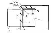
- FIG. 3 is a diagram showing a part of the cross section of the structure 10 cut by a plane along line BB in FIG.
- the arrows indicate the liquid that descends obliquely in a spiral along the inner peripheral surface of the structure 10 .
- two of the four sides defining the opening 11 to which the duct 90 is connected are the first side 111 and the second side 112.
- a protrusion 100 is provided. More specifically, as shown in FIG. 3, of the four corners of the opening 11, one corner (hereinafter referred to as " Protrusions 100 are provided along the first side 111 and the second side 112 forming ⁇ (referred to as the "most upstream angle"). The uppermost flow angle ⁇ is compared to the other three angles when the liquid flow is decomposed into a first vertical flow and a second vertical flow perpendicular to the vertical direction.
- the projecting portion 100 is a gutter projecting from the inner peripheral surface of the structure 10.
- the projecting portion 100 includes a first member 100a1 and a second member 100a2.
- the first member 100a1 is provided along the first side 111, which is one of the two sides forming the most upstream angle ⁇ .
- the first side 111 is the upper side of the two sides vertically facing each other in the opening 11 of the structure 10 .
- the first member 100a1 is fixed to the inner peripheral surface of the structure 10 by welding, for example.
- the second member 100a2 is provided along the second side 112, which is the other side of the two sides forming the most upstream angle ⁇ .
- the second side 112 is the left side of the two sides facing each other in the left-right direction in the opening 11 of the structure 10 .
- the second member 100a2 is also fixed to the inner peripheral surface of the structure 10 by welding, for example.
- the first member 100a1 is provided to prevent the liquid from flowing into the opening 11 from the first side 111 side of the two sides forming the most upstream angle ⁇ .
- the second member 100a2 is provided to prevent the liquid from flowing into the opening 11 from the second side 112 side of the two sides forming the uppermost flow angle ⁇ .
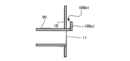
- FIG. 4 is a diagram showing a cross section of the structure 10 and the first member 100a1 cut by a plane along line CC in FIG.
- the cross section of the first member 100a1 is L-shaped.
- the first member 100a1 is composed of a horizontal portion that horizontally protrudes from the inner peripheral surface of the structure 10, and a vertical portion that vertically protrudes upward from the tip of the horizontal portion. Therefore, the first groove 100b1 is defined by the first member 100a1 and the inner peripheral surface of the structure 10.
- the length W of the first member 100a1 in the radial direction of the structure 10 is 40 mm.
- the length W of the first member 100a1 is determined in consideration of the increase in pressure loss caused by the projection of the first member 100a1 into the structure 10. As shown in FIG. In this embodiment, the length W of the first member 100a1 is set to 40 mm in order to keep the pressure loss in the exhaust gas purifier 1A within 1000 Pa.
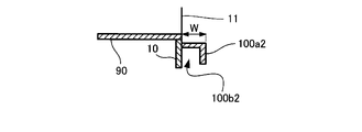
- FIG. 5 is a diagram showing a cross section of the structure 10 and the second member 100a2 cut by a plane along line DD in FIG.
- the cross section of the second member 100a2 is L-shaped like the cross section of the first member 100a1.
- the second member 100a2 is composed of a radial portion that protrudes radially from the inner peripheral surface of the structure 10 into the inner envelope, and a circumferential portion that protrudes in the circumferential direction from the tip of the radial portion. . Therefore, the second groove 100b2 is defined by the second member 100a2 and the inner peripheral surface of the structure 10.
- the first groove 100b1 is continuous with the second groove 100b2.
- the length W of the second member 100a2 in the radial direction of the structure 10 is also 40 mm.
- the reason why the projecting portion 100 is formed by fixing the first member 100a1 and the second member 100a2 to the inner peripheral surface of the structure 10 by welding is as follows.
- the tip of the duct 90 is protruded from the opening 11 provided in the structure 10 toward the inside of the structure 10, and the plate-like first member 100a1 is welded to the tip.
- the welding operation becomes difficult depending on the length W of the first member 100a1, which hinders the manufacture of the exhaust gas purification device 1A.
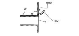
- the first groove 100b1 may be formed as shown in FIG.
- the first groove 100b1 may be formed as shown in FIG.
- the first groove 100b1 may be formed using a first member 100a1 having an arc-shaped cross section, and as shown in FIG.
- the first groove 100b1 may be formed by attaching obliquely to the inner peripheral surface of the body 10 .
- the second groove 100b2 may be similarly formed in the manner of FIG. 6, FIG. 7 or FIG.
- the projecting portion 100 receives the liquid that descends obliquely while swirling along the inner peripheral surface of the structure 10 .
- the liquid received by the protrusion 100 is guided along the first groove 100b1 and the second groove 100b2 and flows down to the bottom of the structure 10. FIG. That is, the liquid does not drip into the flow path of the exhaust gas. Therefore, pressure loss is suppressed.
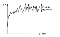
- FIG. 9 and 10 are diagrams for explaining the effects of this embodiment. More specifically, FIG. 9 is a diagram showing an example of a simulation result of pressure fluctuations in an exhaust gas purifying device in which the projecting portion 100 is removed from the exhaust gas purifying device 1A, ie, a conventional cyclone type exhaust gas purifying device.
- FIG. 10 is a diagram showing an example of simulation results of pressure fluctuations in the exhaust gas purifier 1A in this embodiment.
- the pressure loss caused by the liquid dropping diagonally while swirling on the inner peripheral surface of the structure 10 drips into the flow path of the exhaust gas. A pressure fluctuation of 300 Pa occurs.
- the exhaust gas purifier 1A the liquid descending obliquely while swirling on the inner peripheral surface of the structure 10 does not drip into the flow path, and the pressure fluctuation is suppressed to about 100 Pa.
- FIG. 11 is a diagram showing a configuration example of an exhaust gas purification device 1B according to a second embodiment of the present disclosure.
- the same reference numerals are assigned to the same components as in FIG.
- the exhaust gas purification device 1B differs from the exhaust gas purification device 1A in that it includes a flow path 150 that communicates with the projecting portion 100 .
- Flow path 15 is provided along the outer circumference of duct 90 .
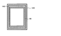
- FIG. 12 is a diagram showing an example of a cross section of the vicinity of the exhaust gas purifier 1B to which the duct 90 is connected.
- the exhaust gas purifier 1B includes a pipe 120, a flange 130, and a wall member 140.
- the tip of duct 90 protrudes into structure 10 through opening 11 .
- a flange 130 is connected to the tip of the duct 90 .
- Flange 130 protrudes from the outer peripheral surface of duct 90 .
- the flanges 130 are provided on the four sides forming the outer circumference of the tip of the duct 90, but there may be sides on which the flanges 130 are not provided.
- tube 120 forms a double tube with part of duct 90 .
- the tube 120 is installed concentrically with the duct 90 so as to surround the duct 90 . That is, the inner peripheral surface of the pipe 120 faces the outer peripheral surface of the duct 90 with a gap therebetween.
- Tube 120 has a first end 121 and a second end 122 .
- a first end 121 of tube 120 is connected to the outer peripheral surface of structure 10 .
- Second end 122 of tube 120 and duct 90 are connected to wall member 140 .
- the projecting portion 100 is formed by the outer peripheral surface of the portion 91 of the duct 90 that projects toward the inside of the structure 10 and the flange 130 .
- Flow path 150 is the space between the inner peripheral surface of tube 120 and the outer peripheral surface of duct 90 .
- flow path 150 is formed by the inner peripheral surface of pipe 120 , the outer peripheral surface of a portion of duct 90 , and wall member 140 .
- the liquid received by the protruding portion 100 flows down to the bottom of the structure 10 via the flow path 150 .
- the projecting portion 100 receives the liquid descending obliquely while swirling along the inner peripheral surface of the structure 10 . Liquid received by protrusion 100 flows down to the bottom of structure 10 via channel 150 . That is, the liquid does not drip into the flow path of the exhaust gas. Therefore, pressure loss is suppressed.
- the liquid flowing through the flow path 150 can cool the exhaust gas flowing through the duct 90 while suppressing the pressure loss due to the contact between the exhaust gas and the waste water. Pressure loss can be further reduced by reducing the volumetric flow rate of the exhaust gas by cooling. It is considered that the liquid flowing through the flow path 150 contains the used absorbent, and the temperature of the used absorbent increases when sulfur oxides are absorbed. However, since the amount of the absorbent sprayed into the structure 10 from the spray device 20 is very large, the temperature rise in the case of complete heat exchange until it reaches the same temperature as the exhaust gas is about several degrees Celsius compared to the temperature of seawater. becomes. In this way, even if the temperature of the liquid flowing through the flow path 150 rises somewhat, the temperature of the exhaust gas flowing through the duct 90 is generally 250 to 350° C., so it can sufficiently act as cooling water for this exhaust gas. .
- the exhaust gas purifier 1A in the first embodiment is an open-loop type exhaust gas purifier that takes in seawater SW acting as an absorbent from around the ship 2 and discharges the used absorbent to the outside of the ship 2 .
- the technical features of the first embodiment may be applied to a closed-loop type exhaust gas purifier that reuses the used absorbent.
- the technical features of the second embodiment may be applied to a closed-loop exhaust gas purifier. Even if it is a closed-loop type exhaust gas purifying device, if it is a cyclone type exhaust gas purifying device, the liquid that descends obliquely while rotating on the inner peripheral surface of the structure will become drops and drip into the flow path of the exhaust gas. This is because pressure loss may occur due to
- FIG. 14 is a diagram showing an example in which the technical features of the first embodiment are applied to a closed-loop exhaust gas purifier.
- a constant amount of absorbent is stored in the tank 40 in advance.
- the exhaust gas purifier 1C does not have a water absorption pipe 30.
- the suction port of the pump 70 is connected to the tank 40 via the circulation pipe 38 .
- the pump 70 sucks the absorbent stored in the tank 40 through the circulation pipe 38 and sends it out to the spray device 20 through the water pipe 32 .
- the used absorbent returned to the tank 40 is reused as the absorbent after neutralization and aeration. Since the exhaust gas purifier 1C also has the protrusion 100 similar to that of the first embodiment, the same effects as those of the exhaust gas purifier 1A of the first embodiment can be obtained.
- 14 has a second pump different from the pump 70 and the water suction pipe 30, and the water suction pipe 30 is connected to the tank 40 via the second pump. may be In this configuration, when the amount of the absorbent stored in the tank 40 falls below a predetermined threshold value, the tank 40 can be filled with water by the second pump. The capacity of the second pump may be less than the capacity of pump 70 .
- FIG. 15 is a diagram showing an example of applying the technical features of the first embodiment to an exhaust gas purifier of a hybrid system.
- An exhaust gas purifier 1D shown in FIG. 15 includes a water absorption pipe 30 and a circulation pipe 38 .
- the suction port of the pump 70 is connected to the water suction pipe 30 and the circulation pipe 38 via a switching valve (not shown).
- one of the water suction pipe 30 and the circulation pipe 38 communicates with the suction port of the pump 70 by switching a switching valve (not shown).
- the exhaust gas purifier 1D functions as an open loop type exhaust gas purifier.
- the exhaust gas purifier 1D functions as a closed loop type exhaust gas purifier.
- exhaust gas can be purified in an open-loop type in sea areas where regulations on wastewater to the ocean are loose, while exhaust gas can be purified in a closed-loop type in sea areas where wastewater discharge regulations are strict.
- An example of a sea area where wastewater regulations are loose is the open ocean.
- Coastal seas are one example of seas where wastewater regulations are strict.
- the exhaust gas purifier 1D shown in FIG. 15 may be modified to have a configuration in which the circulation pipe 38 is connected to the water absorption pipe 30 via a switching valve. This configuration may be modified to a configuration in which the above-described second pump is further provided and the seawater sucked by the second pump is injected into the tank 40 via the circulation pipe 38 .
- a configuration in which the circulation pipe 38 is connected to the water pipe 32 is also conceivable. is required.
- the vessel 2 in each of the above embodiments is a vessel that navigates the ocean, it may be a vessel that navigates freshwater areas.
- sodium hydroxide, magnesium hydroxide, or the like may be added to the water sucked from around the ship 2 to replenish the alkali component.
- the absorbing liquid in the present disclosure is not limited to seawater, and may be an alkaline aqueous solution containing an alkaline component.
- the alkali component is not limited to HCO 3 - .
- One aspect of the exhaust gas purifying apparatus of the present disclosure is a cyclone type exhaust gas purifying apparatus comprising a cylindrical structure 10, a duct 90, and a spray device. 20 and a protrusion 100 .
- the structure 10 is provided with a rectangular opening 11 having four corners.
- Duct 90 is connected to opening 11 of structure 10 .
- Exhaust gas generated by combustion of fossil fuel flows into the duct 90 .
- the spray device 20 sprays into the structure 10 an absorption liquid containing an alkaline component for absorbing sulfur oxides contained in the exhaust gas.
- the projecting portion 100 is positioned most upstream in the flow of the absorbing liquid that obliquely descends along the inner peripheral surface of the structure 10 after the sulfur oxides are absorbed, among the four corners of the opening 11 of the structure 10. It is provided along two sides (first side 111 and second side 112) forming one corner (most upstream angle ⁇ ).
- the protrusion 100 receives the liquid that descends obliquely while swirling along the inner peripheral surface of the structure 10 . Since the liquid received by the projecting portion 100 is guided along the projecting portion 100 and flows down to the bottom of the structure 10, the liquid does not drip into the flow path of the exhaust gas and flows along the inner peripheral surface of the structure 10. The pressure loss caused by the liquid descending obliquely while swirling is suppressed.
- the projecting portion 100 may include a first member 100a1 and a second member 100a2.
- the first member 100a1 is one of the four corners of the opening 11 of the structure 10 that is positioned most upstream in the flow of the absorption liquid that has absorbed the sulfur oxides that descends obliquely along the inner peripheral surface of the structure 10. It is provided along the first side 111 which is one side of the first side 111 and the second side 112 forming the angle (most upstream angle ⁇ ).
- the second member 100 a 2 is provided along the second side 112 that is the other side of the first side 111 and the second side 112 .
- the projecting portion can be formed by retrofitting the first member 100a1 and the second member 100a2 to the structure.
- the first groove 100b1 is defined by the inner peripheral surface of the structure 10 and the first member 100a1.
- the second groove 100b2 that is continuous with the first groove 100b1 is defined by the inner peripheral surface of the structure 10 and the second member 100a2.
- the liquid descending obliquely while swirling along the inner peripheral surface of the structure 10 is guided by the first groove 100b1 and the second groove 100b2 and flows down to the bottom of the structure 10 .
- This aspect also suppresses the pressure loss caused by the liquid descending obliquely while swirling along the inner peripheral surface of the structure 10 .
- the cross section of the first member 100a1 cut by a plane perpendicular to the first side 111 is L-shaped
- the cross section of the first member 100a1 cut by a plane perpendicular to the second side 112 is L-shaped.
- the cross section of the two-member 100a2 may be L-shaped.
- the first member 100a1 is welded to the inner peripheral surface of the structure 10 along the first side 111
- the second member 100a2 is welded to the inner peripheral surface of the structure 10 along the second side 112. Further, by welding the first member 100a1 and the second member 100a2 together, it is possible to easily manufacture the exhaust gas purification apparatus of the present disclosure.
- cyclone type exhaust gas purifier may include a flow path 150 that communicates with the projecting portion 100 and is provided along the outer circumference of the duct 90 .
- the liquid received by the projecting portion flows through the flow path 150 provided along the outer periphery of the duct 90, so that the liquid received by the projecting portion 100 flows through the duct 90. It can be used for cooling the exhaust gas flowing into the structure 10 .
- the tip of the duct 90 may protrude into the structure 10 through the opening 11 .
- the exhaust gas purifier of this aspect may include a flange 130, a pipe 120, and a wall member 140 described below.
- Flange 130 is provided at the tip of duct 90 protruding toward the inside of structure 10 through opening 11 .
- Tube 120 has a first end and a second end and surrounds duct 90 . Also, the first end of the tube 120 is connected to the outer peripheral surface of the structure 10 .
- Wall member 140 connects the second end of tube 120 and duct 90 .
- the projecting portion 100 is formed by the flange 130 and the outer peripheral surface of the portion of the duct 90 that projects toward the inside of the structure 10 .
- the flow path 150 is formed by the inner peripheral surface of the pipe 120 , the outer peripheral surface of a portion of the duct 90 , and the wall member 140 .
- the liquid received by the projecting portion 100 can also be used to cool the exhaust gas flowing into the structure 10 through the duct 90 .
Landscapes
- Chemical & Material Sciences (AREA)
- Engineering & Computer Science (AREA)
- Analytical Chemistry (AREA)
- General Chemical & Material Sciences (AREA)
- Oil, Petroleum & Natural Gas (AREA)
- Chemical Kinetics & Catalysis (AREA)
- Environmental & Geological Engineering (AREA)
- Health & Medical Sciences (AREA)
- Biomedical Technology (AREA)
- Combustion & Propulsion (AREA)
- General Engineering & Computer Science (AREA)
- Mechanical Engineering (AREA)
- Treating Waste Gases (AREA)
- Gas Separation By Absorption (AREA)
- Exhaust Gas After Treatment (AREA)
Abstract
Priority Applications (2)
| Application Number | Priority Date | Filing Date | Title |
|---|---|---|---|
| KR1020227046362A KR20230016692A (ko) | 2021-01-19 | 2021-11-26 | 사이클론식의 배기가스 정화 장치 |
| CN202180045247.3A CN115720529A (zh) | 2021-01-19 | 2021-11-26 | 旋风式的排气净化装置 |
Applications Claiming Priority (2)
| Application Number | Priority Date | Filing Date | Title |
|---|---|---|---|
| JP2021-006214 | 2021-01-19 | ||
| JP2021006214A JP2022110669A (ja) | 2021-01-19 | 2021-01-19 | サイクロン式の排ガス浄化装置 |
Publications (1)
| Publication Number | Publication Date |
|---|---|
| WO2022158116A1 true WO2022158116A1 (fr) | 2022-07-28 |
Family
ID=82549650
Family Applications (1)
| Application Number | Title | Priority Date | Filing Date |
|---|---|---|---|
| PCT/JP2021/043305 Ceased WO2022158116A1 (fr) | 2021-01-19 | 2021-11-26 | Système de purification de gaz d'échappement cyclonique |
Country Status (4)
| Country | Link |
|---|---|
| JP (1) | JP2022110669A (fr) |
| KR (1) | KR20230016692A (fr) |
| CN (1) | CN115720529A (fr) |
| WO (1) | WO2022158116A1 (fr) |
Cited By (1)
| Publication number | Priority date | Publication date | Assignee | Title |
|---|---|---|---|---|
| CN120618216A (zh) * | 2025-05-15 | 2025-09-12 | 盘山县职业教育中心 | 一种用于石油提炼烟气净化处理的湿式处理器 |
Citations (7)
| Publication number | Priority date | Publication date | Assignee | Title |
|---|---|---|---|---|
| JPS5522360A (en) * | 1978-08-08 | 1980-02-18 | Babcock Hitachi Kk | Vapor-liquid contacting apparatus |
| JPS5654929U (fr) * | 1979-10-01 | 1981-05-13 | ||
| JPS5878131U (ja) * | 1981-11-16 | 1983-05-26 | 石川島播磨重工業株式会社 | ガス吸収塔スケ−リング防止装置 |
| JPH05293333A (ja) * | 1991-08-09 | 1993-11-09 | Babcock Hitachi Kk | 湿式排煙脱硫装置 |
| JPH1119457A (ja) * | 1997-07-04 | 1999-01-26 | Niigata Eng Co Ltd | 塩化水素ガス吸収装置 |
| WO2008087769A1 (fr) * | 2007-01-17 | 2008-07-24 | Babcock-Hitachi Kabushiki Kaisha | Equipement de désulfuration par voie humide des gaz de combustion |
| JP2015532205A (ja) * | 2012-10-23 | 2015-11-09 | バブコック・アンド・ウィルコックス・パワー・ジェネレイション・グループ・インコーポレイテッドBabcock & Wilcox Power Generation Group,Inc. | 湿式煙道ガス脱硫におけるスケール堆積の制御システム及び方法 |
Family Cites Families (2)
| Publication number | Priority date | Publication date | Assignee | Title |
|---|---|---|---|---|
| CN102600701B (zh) * | 2012-01-13 | 2014-01-15 | 浙江天蓝环保技术股份有限公司 | 一种烟气湿法脱硫的工艺及装置 |
| CN210699380U (zh) * | 2019-09-24 | 2020-06-09 | 石城县柏邺文具有限公司 | 一种量角尺雕刻用烟气处理装置 |
-
2021
- 2021-01-19 JP JP2021006214A patent/JP2022110669A/ja not_active Withdrawn
- 2021-11-26 CN CN202180045247.3A patent/CN115720529A/zh active Pending
- 2021-11-26 KR KR1020227046362A patent/KR20230016692A/ko not_active Ceased
- 2021-11-26 WO PCT/JP2021/043305 patent/WO2022158116A1/fr not_active Ceased
Patent Citations (7)
| Publication number | Priority date | Publication date | Assignee | Title |
|---|---|---|---|---|
| JPS5522360A (en) * | 1978-08-08 | 1980-02-18 | Babcock Hitachi Kk | Vapor-liquid contacting apparatus |
| JPS5654929U (fr) * | 1979-10-01 | 1981-05-13 | ||
| JPS5878131U (ja) * | 1981-11-16 | 1983-05-26 | 石川島播磨重工業株式会社 | ガス吸収塔スケ−リング防止装置 |
| JPH05293333A (ja) * | 1991-08-09 | 1993-11-09 | Babcock Hitachi Kk | 湿式排煙脱硫装置 |
| JPH1119457A (ja) * | 1997-07-04 | 1999-01-26 | Niigata Eng Co Ltd | 塩化水素ガス吸収装置 |
| WO2008087769A1 (fr) * | 2007-01-17 | 2008-07-24 | Babcock-Hitachi Kabushiki Kaisha | Equipement de désulfuration par voie humide des gaz de combustion |
| JP2015532205A (ja) * | 2012-10-23 | 2015-11-09 | バブコック・アンド・ウィルコックス・パワー・ジェネレイション・グループ・インコーポレイテッドBabcock & Wilcox Power Generation Group,Inc. | 湿式煙道ガス脱硫におけるスケール堆積の制御システム及び方法 |
Cited By (1)
| Publication number | Priority date | Publication date | Assignee | Title |
|---|---|---|---|---|
| CN120618216A (zh) * | 2025-05-15 | 2025-09-12 | 盘山县职业教育中心 | 一种用于石油提炼烟气净化处理的湿式处理器 |
Also Published As
| Publication number | Publication date |
|---|---|
| KR20230016692A (ko) | 2023-02-02 |
| CN115720529A (zh) | 2023-02-28 |
| JP2022110669A (ja) | 2022-07-29 |
Similar Documents
| Publication | Publication Date | Title |
|---|---|---|
| KR101959401B1 (ko) | 배기가스 처리장치의 배출 세정액 내의 유해가스 제거 시스템 및 방법 | |
| US8496742B2 (en) | Wet flue-gas desulfurization equipment | |
| JP2014188406A (ja) | 海水排煙脱硫装置とその運用方法 | |
| JP2013193653A (ja) | イナートガス供給システム | |
| CN105879555B (zh) | 一种船舶低速柴油机废气复合洗涤装置 | |
| WO2008035703A1 (fr) | Appareil de désulfuration d'echappement de type humide | |
| KR101638803B1 (ko) | 배기가스 정화장치 | |
| KR20180038420A (ko) | 다수의 플러드형 스크러버 헤드들을 갖는 다중 레벨 가스 스크러버 | |
| JP2015178084A (ja) | 湿式集塵装置 | |
| WO2022158116A1 (fr) | Système de purification de gaz d'échappement cyclonique | |
| KR101981066B1 (ko) | 부식 방지 기능을 가진 배기가스 처리 시스템 | |
| CN108479324B (zh) | 一种小型化的船舶脱硫降硝除尘装置 | |
| CN212594923U (zh) | 一种垃圾焚烧烟气喷淋脱酸塔 | |
| CN2305242Y (zh) | 湿式复合型锅炉烟气净化装置 | |
| CN205700139U (zh) | 一种锅炉废气净化除雾装置 | |
| JP7323076B2 (ja) | 排ガス浄化装置 | |
| KR101838591B1 (ko) | 오토퍼징기능을 가지는 선박의 황산화물 제거장치용 모니터링 장치 및 그 방법 | |
| JP7323077B2 (ja) | 排ガス浄化装置 | |
| KR101908561B1 (ko) | 다중 리액터와 선형 커넥터를 구비한 scr 시스템 | |
| TWI802860B (zh) | 脫硫裝置的吸收塔 | |
| CN223324327U (zh) | 一种用于化工工业锅炉的尾气脱硫装置 | |
| JPH06285328A (ja) | 簡易型排煙脱硫装置 | |
| CN215585986U (zh) | 一种光催化氧化协同治理废气的喷淋塔 | |
| KR20210066881A (ko) | 드레인 배출 장치 | |
| JP2024138783A (ja) | 排ガス処理装置 |
Legal Events
| Date | Code | Title | Description |
|---|---|---|---|
| 121 | Ep: the epo has been informed by wipo that ep was designated in this application |
Ref document number: 21921219 Country of ref document: EP Kind code of ref document: A1 |
|
| ENP | Entry into the national phase |
Ref document number: 20227046362 Country of ref document: KR Kind code of ref document: A |
|
| NENP | Non-entry into the national phase |
Ref country code: DE |
|
| 122 | Ep: pct application non-entry in european phase |
Ref document number: 21921219 Country of ref document: EP Kind code of ref document: A1 |
|
| WWR | Wipo information: refused in national office |
Ref document number: 1020227046362 Country of ref document: KR |