WO2022158129A1 - Dispositif de revêtement double face - Google Patents
Dispositif de revêtement double face Download PDFInfo
- Publication number
- WO2022158129A1 WO2022158129A1 PCT/JP2021/044043 JP2021044043W WO2022158129A1 WO 2022158129 A1 WO2022158129 A1 WO 2022158129A1 JP 2021044043 W JP2021044043 W JP 2021044043W WO 2022158129 A1 WO2022158129 A1 WO 2022158129A1
- Authority
- WO
- WIPO (PCT)
- Prior art keywords
- die
- paint
- gas
- base material
- double
- Prior art date
- Legal status (The legal status is an assumption and is not a legal conclusion. Google has not performed a legal analysis and makes no representation as to the accuracy of the status listed.)
- Ceased
Links
Images


Classifications
-
- B—PERFORMING OPERATIONS; TRANSPORTING
- B05—SPRAYING OR ATOMISING IN GENERAL; APPLYING FLUENT MATERIALS TO SURFACES, IN GENERAL
- B05C—APPARATUS FOR APPLYING FLUENT MATERIALS TO SURFACES, IN GENERAL
- B05C5/00—Apparatus in which liquid or other fluent material is projected, poured or allowed to flow on to the surface of the work
- B05C5/02—Apparatus in which liquid or other fluent material is projected, poured or allowed to flow on to the surface of the work the liquid or other fluent material being discharged through an outlet orifice by pressure, e.g. from an outlet device in contact or almost in contact, with the work
- B05C5/0254—Coating heads with slot-shaped outlet
-
- B—PERFORMING OPERATIONS; TRANSPORTING
- B05—SPRAYING OR ATOMISING IN GENERAL; APPLYING FLUENT MATERIALS TO SURFACES, IN GENERAL
- B05C—APPARATUS FOR APPLYING FLUENT MATERIALS TO SURFACES, IN GENERAL
- B05C13/00—Means for manipulating or holding work, e.g. for separate articles
- B05C13/02—Means for manipulating or holding work, e.g. for separate articles for particular articles
-
- B—PERFORMING OPERATIONS; TRANSPORTING
- B05—SPRAYING OR ATOMISING IN GENERAL; APPLYING FLUENT MATERIALS TO SURFACES, IN GENERAL
- B05C—APPARATUS FOR APPLYING FLUENT MATERIALS TO SURFACES, IN GENERAL
- B05C9/00—Apparatus or plant for applying liquid or other fluent material to surfaces by means not covered by any preceding group, or in which the means of applying the liquid or other fluent material is not important
- B05C9/04—Apparatus or plant for applying liquid or other fluent material to surfaces by means not covered by any preceding group, or in which the means of applying the liquid or other fluent material is not important for applying liquid or other fluent material to opposite sides of the work
-
- B—PERFORMING OPERATIONS; TRANSPORTING
- B05—SPRAYING OR ATOMISING IN GENERAL; APPLYING FLUENT MATERIALS TO SURFACES, IN GENERAL
- B05C—APPARATUS FOR APPLYING FLUENT MATERIALS TO SURFACES, IN GENERAL
- B05C9/00—Apparatus or plant for applying liquid or other fluent material to surfaces by means not covered by any preceding group, or in which the means of applying the liquid or other fluent material is not important
- B05C9/06—Apparatus or plant for applying liquid or other fluent material to surfaces by means not covered by any preceding group, or in which the means of applying the liquid or other fluent material is not important for applying two different liquids or other fluent materials, or the same liquid or other fluent material twice, to the same side of the work
-
- B—PERFORMING OPERATIONS; TRANSPORTING
- B05—SPRAYING OR ATOMISING IN GENERAL; APPLYING FLUENT MATERIALS TO SURFACES, IN GENERAL
- B05C—APPARATUS FOR APPLYING FLUENT MATERIALS TO SURFACES, IN GENERAL
- B05C9/00—Apparatus or plant for applying liquid or other fluent material to surfaces by means not covered by any preceding group, or in which the means of applying the liquid or other fluent material is not important
- B05C9/08—Apparatus or plant for applying liquid or other fluent material to surfaces by means not covered by any preceding group, or in which the means of applying the liquid or other fluent material is not important for applying liquid or other fluent material and performing an auxiliary operation
-
- H—ELECTRICITY
- H01—ELECTRIC ELEMENTS
- H01M—PROCESSES OR MEANS, e.g. BATTERIES, FOR THE DIRECT CONVERSION OF CHEMICAL ENERGY INTO ELECTRICAL ENERGY
- H01M10/00—Secondary cells; Manufacture thereof
- H01M10/04—Construction or manufacture in general
- H01M10/0404—Machines for assembling batteries
-
- H—ELECTRICITY
- H01—ELECTRIC ELEMENTS
- H01M—PROCESSES OR MEANS, e.g. BATTERIES, FOR THE DIRECT CONVERSION OF CHEMICAL ENERGY INTO ELECTRICAL ENERGY
- H01M4/00—Electrodes
- H01M4/02—Electrodes composed of, or comprising, active material
- H01M4/04—Processes of manufacture in general
-
- H—ELECTRICITY
- H01—ELECTRIC ELEMENTS
- H01M—PROCESSES OR MEANS, e.g. BATTERIES, FOR THE DIRECT CONVERSION OF CHEMICAL ENERGY INTO ELECTRICAL ENERGY
- H01M4/00—Electrodes
- H01M4/02—Electrodes composed of, or comprising, active material
- H01M4/04—Processes of manufacture in general
- H01M4/0402—Methods of deposition of the material
- H01M4/0404—Methods of deposition of the material by coating on electrode collectors
-
- H—ELECTRICITY
- H01—ELECTRIC ELEMENTS
- H01M—PROCESSES OR MEANS, e.g. BATTERIES, FOR THE DIRECT CONVERSION OF CHEMICAL ENERGY INTO ELECTRICAL ENERGY
- H01M4/00—Electrodes
- H01M4/02—Electrodes composed of, or comprising, active material
- H01M4/13—Electrodes for accumulators with non-aqueous electrolyte, e.g. for lithium-accumulators; Processes of manufacture thereof
- H01M4/139—Processes of manufacture
-
- Y—GENERAL TAGGING OF NEW TECHNOLOGICAL DEVELOPMENTS; GENERAL TAGGING OF CROSS-SECTIONAL TECHNOLOGIES SPANNING OVER SEVERAL SECTIONS OF THE IPC; TECHNICAL SUBJECTS COVERED BY FORMER USPC CROSS-REFERENCE ART COLLECTIONS [XRACs] AND DIGESTS
- Y02—TECHNOLOGIES OR APPLICATIONS FOR MITIGATION OR ADAPTATION AGAINST CLIMATE CHANGE
- Y02E—REDUCTION OF GREENHOUSE GAS [GHG] EMISSIONS, RELATED TO ENERGY GENERATION, TRANSMISSION OR DISTRIBUTION
- Y02E60/00—Enabling technologies; Technologies with a potential or indirect contribution to GHG emissions mitigation
- Y02E60/10—Energy storage using batteries
Definitions
- the present disclosure relates to a double-sided coating device.
- an electrode active material layer is formed by applying a coating material containing an electrode active material on both sides of the substrate while conveying a substrate such as a metal foil by a roll-to-roll method.
- a double-side coating apparatus a structure is known in which first a first paint is applied to the first surface of the substrate and dried, and then a second paint is applied to the second surface of the substrate and dried. ing.
- first a first paint is applied to the first surface of the substrate and dried, and then a second paint is applied to the second surface of the substrate and dried. ing.
- first the first paint is applied to the first surface of the base material, then the second paint is applied to the second surface, and then the first paint and the second paint are dried at once.
- a tool has been proposed.
- the first paint can be applied to the first surface while the second surface is supported by the backup roll.
- the second coating is applied to the second surface, the first surface coated with the undried first coating cannot be supported by the backup roll. Therefore, it is necessary to apply the second paint to the second surface while the substrate is suspended in the air.
- Patent Document 1 proposes a thin film coating apparatus in which the tip of a nozzle portion that ejects paint is brought into contact with a substrate being conveyed, and the nozzle portion supports the substrate while applying the paint.
- the present disclosure has been made in view of such circumstances, and its purpose is to provide a technique for suppressing the deflection and vibration of the substrate while suppressing the generation of particles in a double-sided coating apparatus.
- a certain aspect of the present disclosure is a double-sided coating device.
- This apparatus comprises a conveying mechanism for continuously conveying a long substrate having a first surface and a second surface opposite to the first surface, and a first die for applying a first paint to the first surface.
- a second die that is positioned downstream of the first die in the direction of conveyance of the base material and that applies the second coating material to the second surface;
- a support that supports the substrate at a target coating height at which the second surface is separated from the second die by a predetermined amount by means of gas transfer to the second surface, including discharge and suction of gas interposed between the second surface and the second surface. and a part.
- FIG. 4 is a plan view of a second die; It is sectional drawing of the 2nd die
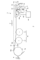
- FIG. 1 is a side view schematically showing a double-sided coating device 1 according to an embodiment.
- FIG. 2 is a side view showing an enlarged part of the double-sided coating apparatus 1.
- the double-sided coating apparatus 1 includes a conveying mechanism 2, a first die 4, a second die 6, a support section 8, and a drying oven 10.
- the first die 4 , the second die 6 and the drying oven 10 are arranged in the listed order from the upstream side in the direction A in which the substrate 12 is conveyed by the conveying mechanism 2 .
- the first die 4, the second die 6 and the drying oven 10 are arranged approximately horizontally.
- the support portion 8 is fixed to the outer surface of the second die 6 . Therefore, the second die 6 and the support portion 8 are positioned downstream in the transport direction A from the first die 4 .
- the transport mechanism 2 continuously transports the long thin-film base material 12 .
- the base material 12 is in a wound state, is drawn out from the wound body by the conveying mechanism 2, passes through the first die 4, the second die 6 and the drying oven 10, and is wound up on a winding reel (not shown).
- the conveying mechanism 2 has a roll 14 and a retracting section 16 .
- the roll 14 is located on the upstream side of the second die 6 in the conveying direction A of the substrate 12, and conveys the substrate 12 while supporting it on its peripheral surface.
- the roll 14 of the present embodiment is arranged so that the peripheral surface faces the discharge port of the first die 4 with a predetermined gap (coating gap), and functions as a backup roll.
- the base material 12 has a first surface 12a and a second surface 12b opposite to the first surface 12a.
- the roll 14 conveys the base material 12 and passes it through the gap between the first die 4 and the roll 14 while supporting the second surface 12b on its peripheral surface.
- the first die 4 applies the first paint 18 to the first surface 12 a of the base material 12 passing through the gap between the first die 4 and the roll 14 .
- the first die 4 is oriented so that the ejection port faces the horizontal direction, and is horizontally aligned with the roll 14 .
- the double-sided coating apparatus 1 of the present embodiment is used for manufacturing electrode plates of secondary batteries.
- An electrode plate of a secondary battery is a sheet-shaped electrode material obtained by applying an electrode slurry to a current collector and drying the slurry. Therefore, in the present embodiment, the base material 12 is a secondary battery current collector, and the first paint 18 is a secondary battery electrode slurry. The second paint 20 discharged from the second die 6 is also the electrode slurry of the secondary battery.
- a current collector is, for example, a metal foil.
- the electrode slurry is, for example, a mixture of a positive electrode active material or a negative electrode active material and a solvent.
- a positive electrode plate is produced by coating an aluminum foil with a slurry containing a positive electrode active material such as lithium cobalt oxide or lithium iron phosphate.
- the negative electrode plate is prepared by applying a slurry containing a negative electrode active material such as graphite onto a copper foil.
- the first paint 18 and the second paint 20 may be the same paint or different paints.
- the double-sided coating apparatus 1 can also be used for manufacturing articles other than electrode plates.
- the roll 14 feeds the substrate 12 downstream in the transport direction A with the first surface 12a coated with the first paint 18 facing upward and the second surface 12b not coated with the second paint 20 facing downward.
- the base material 12 is delivered from the roll 14 in a substantially horizontal direction.
- the upper end of the peripheral surface of the roll 14 is located at a position higher than the target coating height H1 of the substrate 12 .
- the height of the position 14a at which the substrate 12 is separated from the peripheral surface of the roll 14, that is, the delivery height H2 is higher than the target coating height H1.
- the target coating height H1 is the height at which the second surface 12b is separated from the second die 6 by a predetermined amount.
- a predetermined coating gap G is formed between the ejection port of the second die 6 and the second surface 12b.
- the delivery height H2 is roughly the same height as the upper end of the peripheral surface of the roll 14, but strictly speaking, the base material 12 is pulled downward by the pulling part 16, so that it shifts slightly below the upper end of the peripheral surface. .
- a retracting section 16 is arranged between the roll 14 and the second die 6 in the conveying direction A.
- the substrate 12 delivered from the roll 14 is drawn by the drawing section 16 so as to approach the target coating height H1.
- the lead-in portion 16 has a suction portion 22 that sucks gas such as atmospheric gas (for example, air).
- the retracting portion 16 can retract the base material 12 downward by sucking the atmospheric gas interposed between the second surface 12b and the suction portion 22 .
- the suction unit 22 can be composed of a known suction roller, suction plate, suction type air knife, or the like.
- the height of the suction part 22 is mechanically adjustable, and is adjusted to an optimum height according to the thickness and mass of the base material 12 .
- the retracting section 16 of the present embodiment has a plurality of suction sections 22 arranged in the transport direction A.
- Two suction units 22 are arranged in the transport direction A in FIGS.
- the plurality of suction units 22 are arranged so that the installation height becomes lower toward the downstream side in the transport direction A.
- the suction portion 22 located downstream in the transport direction A is lower than the suction portion 22 located upstream in the transport direction A, in other words, it is closer to the target coating height H1.
- the substrate 12 is drawn to the target coating height H1 by the drawing-in portion 16, and sent out to the downstream side in the conveying direction A.
- Three or more suction units 22 may be arranged in the transport direction A, or one suction unit 22 may be provided. Further, if the delivery height H2 of the rolls 14 substantially coincides with the target coating height H1, the retraction section 16 may be omitted.
- a second die 6 is arranged on the downstream side in the conveying direction A of the retracting section 16 .
- the second die 6 applies the second paint 20 to the second surface 12b of the base material 12 which is floating in the air. At least the area facing the second die 6 of the base material 12 is suspended in the air.
- the second die 6 is oriented such that the discharge port 50 faces vertically upward, and applies the second paint 20 to the second surface 12b facing vertically downward.
- a support portion 8 is fixed to the outer surface of the second die 6 .
- the support part 8 supports the substrate 12 at the target coating height H1 by transferring the gas to the second surface 12b.
- the transfer of the gas to the second surface 12b includes both the discharge of the gas to the second surface 12b and the suction of the gas (that is, ambient gas) interposed between the second surface 12b and the second surface 12b.
- the gas discharged from the support portion 8 is, for example, atmospheric gas. That is, the support part 8 of the present embodiment supports the substrate 12 at the target coating height H1 by a combination of gas discharge and suction.
- the second die 6 has a first body 24 , a second body 26 , a manifold 38 , a paint channel 48 and a discharge port 50 .
- the first main body 24 and the second main body 26 are elongated in the width direction B of the substrate 12 perpendicular to the conveying direction A. As shown in FIG.
- the first main body 24 is arranged downstream in the transport direction A from the second main body 26 .
- the first main body 24 of the present embodiment has a tapered surface 24a that slopes toward the second main body 26 as it approaches the second surface 12b.
- the second body 26 also has a tapered surface 26a that slopes toward the first body 24 as it approaches the second surface 12b.
- the tapered surfaces 24a and 26a are arranged at the end of the second die 6 on the second surface 12b side.
- a discharge port 50 that opens toward the second surface 12b and a paint flow path 48 that communicates with the discharge port 50 are arranged.
- a sheet-like shim 52 is interposed between the first body 24 and the second body 26 .
- a gap corresponding to the thickness of the shim 52 is formed between the first main body 24 and the second main body 26 .
- This gap constitutes the paint flow path 48 .
- the open end facing the second surface 12b of the gap constitutes the discharge port 50.
- the first main body 24 has a recess elongated in the width direction B on the surface facing the second main body 26 side. This recess forms a manifold 38 . Note that the manifold 38 may be provided on the second main body 26 .
- a supply pipe for the second paint 20 is connected to the manifold 38, and the second paint 20 is supplied from the outside.
- the end of the paint flow path 48 opposite to the discharge port 50 communicates with the manifold 38 .
- the second paint 20 supplied to the manifold 38 flows through the paint flow path 48 and is discharged from the discharge port 50 onto the second surface 12b.
- a support portion 8 is fixed to the outer surface of the second main body 26 facing the upstream side in the conveying direction A. Therefore, the support portion 8 is positioned upstream in the transport direction A from the ejection port 50 .
- the support portion 8 of this embodiment is fixed to the tapered surface 26a.
- the support portion 8 may be fixed to the outer surface of the first main body 24 and positioned downstream in the transport direction A from the discharge port 50 .
- the support portion 8 is fixed to the tapered surface 24a, for example.
- the end of the support portion 8 on the side of the second surface 12b is arranged so as to be flush with the discharge port 50 . Therefore, the support portion 8 and the ejection port 50 are separated by the same distance from the second surface 12b.
- the support section 8 of the present embodiment has a porous material 40, a pipe 42 and an air supply device 44 as an example.
- the porous material 40 is fixed to the tapered surface 26a, and the tip on the side of the second surface 12b faces the second surface 12b.
- the porous material 40 may be fixed to the second body 26 with a fixture such as a bracket, or may be adhered to the second body 26 with an adhesive.
- the tip of the porous material 40 on the side of the second surface 12 b is substantially flush with the discharge port 50 .
- FIG. 3 is a plan view of the second die 6.
- the x marks surrounded by circles represent the flow of gas to be sucked, and the marks surrounded by circles represent the flow of gas to be discharged.
- the porous material 40 of the present embodiment is divided into a plurality of regions having different gas transfer amounts (discharge amount and suction amount). For example, each area is airtightly partitioned by a partition plate.
- a region for discharging gas is referred to as a discharge region 40a
- a region for sucking gas is referred to as a suction region 40b.
- the porous material 40 of this embodiment has a plurality of ejection regions 40a and a plurality of suction regions 40b. At least part of the plurality of ejection regions 40a have different gas ejection amounts.
- at least some of the plurality of suction regions 40b differ from each other in gas suction amounts.
- the plurality of regions are arranged in the width direction B of the base material 12 .
- a plurality of ejection regions 40a and a plurality of suction regions 40b are alternately arranged in the width direction B.
- the more the ejection regions 40a are located outside in the width direction B the more the gas ejection amount decreases, and the more the plurality of suction regions 40b are located outside the width direction B, the more the gas suction amount increases. .
- the retraction amount of the base material 12 can be increased toward the outer side in the width direction B. As shown in FIG.
- the more the plurality of ejection regions 40a are located on the outer side in the width direction B the more the gas ejection amount is increased, and the more the plurality of suction regions 40b are located on the outer side of the width direction B, the more the gas suction amount is decreased.
- the extrusion amount of the base material 12 can be increased toward the outer side in the width direction B.
- the plurality of ejection regions 40a may have the same ejection amount, and the plurality of suction regions 40b may have different suction amounts. Also, the ejection amounts of the plurality of ejection regions 40a may be different from each other, and the suction amounts of the plurality of suction regions 40b may be equal to each other. Also, the plurality of areas may be arranged in the transport direction A. FIG. Further, in the support portion 8, the ejection area 40a may not be divided into a plurality of areas, and the ejection amount may be uniform. Further, the suction area 40b of the support portion 8 may not be divided into a plurality of areas, and the suction amount may be uniform.
- an air supply device 44 is connected to the porous material 40 via a pipe 42 .
- the suction device 44 is composed of, for example, a compressor that discharges gas and a vacuum pump that sucks gas.
- a compressor is connected to each discharge region 40a through a pipe 42, and a vacuum pump is connected to each suction region 40b through a pipe 42.
- Different air supply amounts in the respective discharge regions 40a may be realized by connecting separate compressors to the respective discharge regions 40a, or may be realized by varying the porosity or the like of the respective discharge regions 40a.
- the amount of suction in each suction region 40b may be realized by connecting a separate vacuum pump to each suction region 40b, or by varying the porosity of each suction region 40b. good too.
- the air supply device 44 By driving the air supply device 44, gas is blown from each discharge region 40a to the second surface 12b, and the gas interposed between the second die 6 and the second surface 12b is sucked from each suction region 40b.
- the substrate 12 floats in the air due to the balance between the positive pressure generated by the ejection of gas from each ejection region 40a and the negative pressure generated by the suction of gas from each suction region 40b. It is supported at the working height H1.
- the second paint 20 is applied with a desired coating gap G formed between the base material 12 and the second die 6 and with the flatness of the base material 12 maintained with high accuracy. It can be applied to the second surface 12b.
- the support portion 8 may have another known structure capable of discharging and sucking gas.
- a drying oven 10 is arranged on the downstream side of the second die 6 in the conveying direction A.
- gas injection nozzles 46 for blowing out gas (for example, hot air) for drying the first coating material 18 and the second coating material 20 are provided above and below.
- the substrate 12 having the first paint 18 applied to the first surface 12a and the second paint 20 applied to the second surface 12b is suspended in the drying furnace 10 by the gas jetted from the gas injection nozzle 46. is transported.
- the substrate 12, from which the first coating material 18 and the second coating material 20 have been dried in the course of passing through the drying oven 10, is taken up on a take-up reel after leaving the drying oven 10. As shown in FIG.
- the double-side coating apparatus 1 includes the transport mechanism 2, the first die 4, the second die 6, and the support section 8.
- the transport mechanism 2 continuously transports the substrate 12 having the first surface 12a and the second surface 12b.
- the first die 4 applies the first paint 18 to the first surface 12a.
- the second die 6 is positioned downstream in the transport direction A from the first die 4 and applies the second paint 20 to the second surface 12b.
- the support portion 8 is located downstream of the first die 4 in the conveying direction A, and is capable of discharging gas to the second surface 12b and sucking gas interposed between the support portion 8 and the second surface 12b.
- Substrate 12 is supported at target coating height H1 by transport of the gas involved.
- the support portion 8 (the porous material 40 in this embodiment) is fixed to the outer surface of the second die 6 .
- the base material 12 is supported at one end by a roll 14 and at the other end on the downstream side of the drying oven 10 by a transport roll or a take-up roll (not shown).
- a transport roll or a take-up roll (not shown).
- the portion of the substrate 12 between the two rolls is suspended in the air, and a state in which the substrate 12 is not in contact with the second die 6 can be created.
- the base material 12 in a state of being suspended in the air bends considerably due to its own weight.
- the vibration of the base material 12 due to the rotation of the rolls 14, the hot air from the drying furnace 10, etc. is likely to propagate through the base material 12, making it difficult to stably hold the position of the base material 12. become.
- the base material 12 is distorted and the flatness is lowered.
- the support unit 8 both discharges and sucks the gas to and from the base material 12, so that the target coating height is achieved while the base material 12 is suspended in the air. It supports H1.
- the height of the base material 12 can be adjusted to the target coating height H1 with higher accuracy than when either one is used alone.
- the support portion 8 is fixed to the outer surface of the second die 6 . Therefore, the substrate 12 can be supported at the target coating height H1 at a position extremely close to the ejection port 50 of the second coating material 20 .
- the second paint 20 can be applied to the second surface 12b while the position and flatness of the substrate 12 are maintained with high accuracy. As a result, it is possible to form a coating film of the second paint 20 with higher precision and higher quality.
- the support portion 8 is divided into a plurality of regions with different gas transfer amounts.
- the porous material 40 of the support portion 8 is divided into a plurality of ejection regions 40a and a plurality of suction regions 40b. At least some of the plurality of ejection regions 40a have different gas ejection amounts. At least some of the plurality of suction regions 40b have different gas suction amounts.
- the plurality of regions are arranged in the width direction B of the base material 12 .
- the substrate 12 tends to bend more easily at both ends than at the central portion in the width direction B. As shown in FIG. Therefore, by making it possible to adjust the extrusion amount and the retraction amount of the base material 12 in the width direction B, the flatness of the base material 12 can be further improved.
- the end of the support portion 8 on the second surface 12b side is arranged so as to be flush with the discharge port 50 .
- the tip of the porous material 40 of the support portion 8 is flush with the discharge port 50 .
- the first die 4 may also be provided with the support portion 8 .
- the first paint 18 is applied from the first die 4 to the first surface 12a while the substrate 12 is suspended in the air.
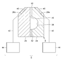
- FIG. 4 is a cross-sectional view of the second die 6 included in the double-sided coating apparatus 1 according to the modification.
- the support portion 8 of this modification transfers the gas to the second surface 12b on both the upstream side and the downstream side in the transport direction A of the discharge port 50 .
- the support 8 as an example has two sets of combinations of the porous material 40 , the pipe 42 and the air supply device 44 .
- One porous material 40 is fixed to the tapered surface 26 a of the second body 26 and the other porous material 40 is fixed to the tapered surface 24 a of the first body 24 .
- Each porous material 40 is connected to a separate air supply device 44 via tubing 42 . Then, gas is discharged and sucked from each porous material 40 to support the base material 12 .
- the two porous materials 40 may be connected to a common air supply device 44 .
- the position and flatness of the portion of the substrate 12 facing the ejection port 50 can be maintained with higher accuracy.
- the vibration of the substrate 12 caused by being exposed to the hot air in the drying oven 10 can Propagation to the opposing portion can be suppressed.
- a coating film of the second paint 20 having a more uniform film thickness can be formed.
- Embodiments may be specified by items described below.
- a support (8) that supports the substrate (12) at a target coating height (H1) at which the second surface (12b) is separated from the second die (6) by a predetermined amount by the transfer of Double-sided coating device (1).
- the support part (8) transfers the gas on both the upstream side and the downstream side in the conveying direction (A) of the discharge port of the second coating material (20).
- the support part (8) is divided into a plurality of regions (40a, 40b) in which the amount of gas transferred is different from each other, 3.
- the plurality of regions (40a, 40b) are arranged in the width direction (B) of the substrate (12), A double-sided coating apparatus (1) according to item 3.
- a double-sided coating apparatus (1) according to item 3.
- the end of the support portion (8) on the second surface (12b) side is arranged so as to be flush with the discharge port (50) of the second paint (20), 5.
- a double-sided coating apparatus (1) according to any one of items 1 to 4.
- the base material (12) is a current collector of a secondary battery
- the first paint (18) and the second paint (20) are secondary battery electrode slurries, A double-sided coating apparatus (1) according to any one of items 1 to 5.
- the present disclosure can be used for double-sided coating equipment.
- 1 double-sided coating device 2 transport mechanism, 4 first die, 6 second die, 8 support part, 12 base material, 12a first surface, 12b second surface, 18 first paint, 20 second paint, 50 discharge Exit, A: Conveying direction, B: Width direction, H1: Target coating height.
Landscapes
- Engineering & Computer Science (AREA)
- Chemical & Material Sciences (AREA)
- Manufacturing & Machinery (AREA)
- Chemical Kinetics & Catalysis (AREA)
- Electrochemistry (AREA)
- General Chemical & Material Sciences (AREA)
- Materials Engineering (AREA)
- Coating Apparatus (AREA)
Abstract
Priority Applications (4)
| Application Number | Priority Date | Filing Date | Title |
|---|---|---|---|
| US18/255,075 US20240001399A1 (en) | 2021-01-20 | 2021-12-01 | Both-sides coating apparatus |
| EP21921231.3A EP4282538A4 (fr) | 2021-01-20 | 2021-12-01 | Dispositif de revêtement double face |
| JP2022577012A JP7769947B2 (ja) | 2021-01-20 | 2021-12-01 | 両面塗工装置 |
| CN202180080069.8A CN116568408A (zh) | 2021-01-20 | 2021-12-01 | 双面涂布装置 |
Applications Claiming Priority (2)
| Application Number | Priority Date | Filing Date | Title |
|---|---|---|---|
| JP2021006873 | 2021-01-20 | ||
| JP2021-006873 | 2021-01-20 |
Publications (1)
| Publication Number | Publication Date |
|---|---|
| WO2022158129A1 true WO2022158129A1 (fr) | 2022-07-28 |
Family
ID=82549676
Family Applications (1)
| Application Number | Title | Priority Date | Filing Date |
|---|---|---|---|
| PCT/JP2021/044043 Ceased WO2022158129A1 (fr) | 2021-01-20 | 2021-12-01 | Dispositif de revêtement double face |
Country Status (5)
| Country | Link |
|---|---|
| US (1) | US20240001399A1 (fr) |
| EP (1) | EP4282538A4 (fr) |
| JP (1) | JP7769947B2 (fr) |
| CN (1) | CN116568408A (fr) |
| WO (1) | WO2022158129A1 (fr) |
Citations (6)
| Publication number | Priority date | Publication date | Assignee | Title |
|---|---|---|---|---|
| JPH0615761U (ja) * | 1992-07-29 | 1994-03-01 | 石川島播磨重工業株式会社 | 塗工装置 |
| JPH0857396A (ja) * | 1994-08-26 | 1996-03-05 | Chugai Ro Co Ltd | ダイコータ |
| JP2005246194A (ja) * | 2004-03-03 | 2005-09-15 | Toyota Motor Corp | 両面塗布装置 |
| JP2011143388A (ja) | 2010-01-18 | 2011-07-28 | Clean Technology Kk | 薄膜塗工装置並びに両面薄膜塗工装置 |
| JP2014079708A (ja) * | 2012-10-17 | 2014-05-08 | Tokyo Ohka Kogyo Co Ltd | 両面塗布装置 |
| JP2019130491A (ja) * | 2018-02-01 | 2019-08-08 | パナソニックIpマネジメント株式会社 | 塗工方法および塗工装置 |
Family Cites Families (12)
| Publication number | Priority date | Publication date | Assignee | Title |
|---|---|---|---|---|
| CA2098784A1 (fr) * | 1992-07-08 | 1994-01-09 | Bentley Boger | Installation et methodes pour deposer un revetement conforme sur des plaquettes de circuits electroniques |
| CA2207801C (fr) * | 1996-06-19 | 2004-03-30 | Hideki Kaido | Pile a electrolyte non aqueux |
| JP2000237650A (ja) * | 1999-02-24 | 2000-09-05 | Toshiba Battery Co Ltd | 電池用電極の塗布装置 |
| JP3314338B2 (ja) * | 1999-06-14 | 2002-08-12 | 株式会社ヒラノテクシード | 塗工装置 |
| JP4865893B2 (ja) * | 2009-09-28 | 2012-02-01 | パナソニック株式会社 | ダイヘッドおよび液体塗布装置 |
| DE202010010497U1 (de) * | 2010-07-21 | 2011-10-24 | Delle Vedove Deutschland Gmbh | Beschichtungsvorrichtung für langgestreckte Werkstücke |
| DE102011002069A1 (de) * | 2011-04-14 | 2012-10-18 | Nordenia Deutschland Gronau Gmbh | Klebstoffdüse zum Aufbringen von Klebstoff auf eine bewegte Materialbahn |
| JP2013107053A (ja) * | 2011-11-22 | 2013-06-06 | Hirano Tecseed Co Ltd | 両面塗工装置 |
| JP2014065000A (ja) * | 2012-09-26 | 2014-04-17 | Dainippon Screen Mfg Co Ltd | 両面塗工装置、両面塗工方法および塗膜形成システム |
| JP6539069B2 (ja) * | 2015-03-09 | 2019-07-03 | 東レエンジニアリング株式会社 | 塗布装置 |
| US20190081317A1 (en) * | 2017-09-11 | 2019-03-14 | Andreas Keil | Web coating and calendering system and method |
| JP7088783B2 (ja) * | 2018-08-21 | 2022-06-21 | 株式会社ヒラノテクシード | 塗工装置 |
-
2021
- 2021-12-01 JP JP2022577012A patent/JP7769947B2/ja active Active
- 2021-12-01 WO PCT/JP2021/044043 patent/WO2022158129A1/fr not_active Ceased
- 2021-12-01 EP EP21921231.3A patent/EP4282538A4/fr active Pending
- 2021-12-01 US US18/255,075 patent/US20240001399A1/en active Pending
- 2021-12-01 CN CN202180080069.8A patent/CN116568408A/zh active Pending
Patent Citations (6)
| Publication number | Priority date | Publication date | Assignee | Title |
|---|---|---|---|---|
| JPH0615761U (ja) * | 1992-07-29 | 1994-03-01 | 石川島播磨重工業株式会社 | 塗工装置 |
| JPH0857396A (ja) * | 1994-08-26 | 1996-03-05 | Chugai Ro Co Ltd | ダイコータ |
| JP2005246194A (ja) * | 2004-03-03 | 2005-09-15 | Toyota Motor Corp | 両面塗布装置 |
| JP2011143388A (ja) | 2010-01-18 | 2011-07-28 | Clean Technology Kk | 薄膜塗工装置並びに両面薄膜塗工装置 |
| JP2014079708A (ja) * | 2012-10-17 | 2014-05-08 | Tokyo Ohka Kogyo Co Ltd | 両面塗布装置 |
| JP2019130491A (ja) * | 2018-02-01 | 2019-08-08 | パナソニックIpマネジメント株式会社 | 塗工方法および塗工装置 |
Non-Patent Citations (1)
| Title |
|---|
| See also references of EP4282538A4 |
Also Published As
| Publication number | Publication date |
|---|---|
| CN116568408A (zh) | 2023-08-08 |
| US20240001399A1 (en) | 2024-01-04 |
| JPWO2022158129A1 (fr) | 2022-07-28 |
| EP4282538A1 (fr) | 2023-11-29 |
| EP4282538A4 (fr) | 2024-07-31 |
| JP7769947B2 (ja) | 2025-11-14 |
Similar Documents
| Publication | Publication Date | Title |
|---|---|---|
| EP4098375B1 (fr) | Appareil de revêtement double face | |
| TWI483786B (zh) | 兩面塗覆裝置 | |
| JP6917329B2 (ja) | 塗布装置 | |
| WO2016143511A1 (fr) | Dispositif de revêtement | |
| WO2022158128A1 (fr) | Dispositif de revêtement double face | |
| JP2014065000A (ja) | 両面塗工装置、両面塗工方法および塗膜形成システム | |
| KR20120022072A (ko) | 성막 장치 | |
| WO2022158129A1 (fr) | Dispositif de revêtement double face | |
| CN116923831A (zh) | 背膜分离装置 | |
| JP4229670B2 (ja) | 薄板状材の搬送方法及び装置 | |
| JP2009174001A (ja) | 成膜装置および成膜方法 | |
| JP2015044138A (ja) | ウエブ塗工装置 | |
| KR102848076B1 (ko) | 전극 제조용 건조 장치 및 이를 이용한 전극의 제조방법 | |
| JP2009209380A (ja) | 成膜装置 | |
| JP2014226620A (ja) | 薄膜の形成方法および薄膜 | |
| JP2017075024A (ja) | シート材のエアフロート装置 | |
| US20110214609A1 (en) | Atmospheric plasma apparatus | |
| CN209697211U (zh) | 浮动厚边吹扫消减装置及粉末静电喷涂装置 | |
| JP2015026733A (ja) | 基板処理装置 | |
| JP2012202650A (ja) | 乾燥装置、および処理装置 | |
| CN221132928U (zh) | 一种柔性功能结构薄膜的卷对卷连续生产设备 | |
| CN220224333U (zh) | 支撑辊及处理设备 | |
| WO2023037640A1 (fr) | Dispositif de séchage | |
| JP5347256B2 (ja) | 塗布物の製造装置および製造方法 | |
| WO2023037574A1 (fr) | Dispositif de séchage |
Legal Events
| Date | Code | Title | Description |
|---|---|---|---|
| 121 | Ep: the epo has been informed by wipo that ep was designated in this application |
Ref document number: 21921231 Country of ref document: EP Kind code of ref document: A1 |
|
| ENP | Entry into the national phase |
Ref document number: 2022577012 Country of ref document: JP Kind code of ref document: A |
|
| WWE | Wipo information: entry into national phase |
Ref document number: 202180080069.8 Country of ref document: CN |
|
| WWE | Wipo information: entry into national phase |
Ref document number: 18255075 Country of ref document: US |
|
| NENP | Non-entry into the national phase |
Ref country code: DE |
|
| ENP | Entry into the national phase |
Ref document number: 2021921231 Country of ref document: EP Effective date: 20230821 |