WO2022158167A1 - Turbine à capacité variable et compresseur de suralimentation - Google Patents
Turbine à capacité variable et compresseur de suralimentation Download PDFInfo
- Publication number
- WO2022158167A1 WO2022158167A1 PCT/JP2021/045835 JP2021045835W WO2022158167A1 WO 2022158167 A1 WO2022158167 A1 WO 2022158167A1 JP 2021045835 W JP2021045835 W JP 2021045835W WO 2022158167 A1 WO2022158167 A1 WO 2022158167A1
- Authority
- WO
- WIPO (PCT)
- Prior art keywords
- exhaust gas
- turbine rotor
- turbine
- groove
- plate
- Prior art date
- Legal status (The legal status is an assumption and is not a legal conclusion. Google has not performed a legal analysis and makes no representation as to the accuracy of the status listed.)
- Ceased
Links
Images


Classifications
-
- F—MECHANICAL ENGINEERING; LIGHTING; HEATING; WEAPONS; BLASTING
- F01—MACHINES OR ENGINES IN GENERAL; ENGINE PLANTS IN GENERAL; STEAM ENGINES
- F01D—NON-POSITIVE DISPLACEMENT MACHINES OR ENGINES, e.g. STEAM TURBINES
- F01D17/00—Regulating or controlling by varying flow
- F01D17/10—Final actuators
- F01D17/12—Final actuators arranged in stator parts
- F01D17/14—Final actuators arranged in stator parts varying effective cross-sectional area of nozzles or guide conduits
- F01D17/16—Final actuators arranged in stator parts varying effective cross-sectional area of nozzles or guide conduits by means of nozzle vanes
- F01D17/165—Final actuators arranged in stator parts varying effective cross-sectional area of nozzles or guide conduits by means of nozzle vanes for radial flow, i.e. the vanes turning around axes which are essentially parallel to the rotor centre line
-
- F—MECHANICAL ENGINEERING; LIGHTING; HEATING; WEAPONS; BLASTING
- F01—MACHINES OR ENGINES IN GENERAL; ENGINE PLANTS IN GENERAL; STEAM ENGINES
- F01D—NON-POSITIVE DISPLACEMENT MACHINES OR ENGINES, e.g. STEAM TURBINES
- F01D25/00—Component parts, details, or accessories, not provided for in, or of interest apart from, other groups
- F01D25/24—Casings; Casing parts, e.g. diaphragms, casing fastenings
-
- F—MECHANICAL ENGINEERING; LIGHTING; HEATING; WEAPONS; BLASTING
- F02—COMBUSTION ENGINES; HOT-GAS OR COMBUSTION-PRODUCT ENGINE PLANTS
- F02B—INTERNAL-COMBUSTION PISTON ENGINES; COMBUSTION ENGINES IN GENERAL
- F02B37/00—Engines characterised by provision of pumps driven at least for part of the time by exhaust
- F02B37/12—Control of the pumps
- F02B37/22—Control of the pumps by varying cross-section of exhaust passages or air passages, e.g. by throttling turbine inlets or outlets or by varying effective number of guide conduits
-
- F—MECHANICAL ENGINEERING; LIGHTING; HEATING; WEAPONS; BLASTING
- F02—COMBUSTION ENGINES; HOT-GAS OR COMBUSTION-PRODUCT ENGINE PLANTS
- F02B—INTERNAL-COMBUSTION PISTON ENGINES; COMBUSTION ENGINES IN GENERAL
- F02B37/00—Engines characterised by provision of pumps driven at least for part of the time by exhaust
- F02B37/12—Control of the pumps
- F02B37/24—Control of the pumps by using pumps or turbines with adjustable guide vanes
-
- Y—GENERAL TAGGING OF NEW TECHNOLOGICAL DEVELOPMENTS; GENERAL TAGGING OF CROSS-SECTIONAL TECHNOLOGIES SPANNING OVER SEVERAL SECTIONS OF THE IPC; TECHNICAL SUBJECTS COVERED BY FORMER USPC CROSS-REFERENCE ART COLLECTIONS [XRACs] AND DIGESTS
- Y02—TECHNOLOGIES OR APPLICATIONS FOR MITIGATION OR ADAPTATION AGAINST CLIMATE CHANGE
- Y02T—CLIMATE CHANGE MITIGATION TECHNOLOGIES RELATED TO TRANSPORTATION
- Y02T10/00—Road transport of goods or passengers
- Y02T10/10—Internal combustion engine [ICE] based vehicles
- Y02T10/12—Improving ICE efficiencies
Definitions
- the present disclosure relates to a variable capacity turbine and a supercharger including the variable capacity turbine.
- This application claims priority based on Japanese Patent Application No. 2021-008190 filed with the Japan Patent Office on January 21, 2021, the contents of which are incorporated herein.
- variable displacement exhaust turbocharger equipped with a variable displacement turbine
- a variable capacity turbine has a plurality of nozzle vanes arranged in the circumferential direction of the turbine rotor in an exhaust gas flow path for sending the exhaust gas from the scroll flow path of the turbine to the turbine rotor.
- the cross-sectional area of the exhaust gas flow path (the flow path between adjacent nozzle vanes) can be adjusted.
- the variable capacity turbine adjusts the cross-sectional area of the exhaust gas flow path to change the flow velocity and pressure of the exhaust gas guided to the turbine rotor, thereby enhancing the supercharging effect.
- Patent Document 1 discloses that unevenness is formed on the wall surface defining the exhaust gas flow path in order to change the flow of the exhaust gas before passing between the nozzle vanes. It doesn't change the flow.
- an object of at least one embodiment of the present disclosure is to provide a variable capacity turbine capable of improving the efficiency of the turbine at low flow rates, and a supercharger including the variable capacity turbine. be.
- a variable capacity turbine includes: a turbine rotor; a scroll passage forming portion that forms a scroll passage on the outer peripheral side of the turbine rotor; an exhaust gas passage forming portion forming an exhaust gas passage for guiding exhaust gas from the scroll passage to the turbine rotor; A variable nozzle unit for adjusting the flow of the exhaust gas in the exhaust gas flow path, the variable nozzle unit including a plurality of nozzle vanes arranged in the exhaust gas flow path and configured to be rotatable about respective rotation centers.
- the exhaust gas flow path forming portion is a first plate member having an annular first plate portion; An annular second plate portion defining the exhaust gas flow path between the first plate portion and the second plate portion, the second plate being arranged closer to the turbine exit side than the first plate portion in the axial direction of the turbine rotor. a second plate member having a portion, The first plate-shaped member has at least one groove extending outwardly from the inner peripheral edge of the first plate in a hub-side channel surface facing the exhaust gas channel of the first plate.
- a turbocharger includes: the variable capacity turbine; a centrifugal compressor configured to be driven by the variable capacity turbine.
- variable capacity turbine capable of improving the efficiency of the turbine at low flow rates and a supercharger including the variable capacity turbine are provided.
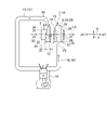
- FIG. 1 is a schematic configuration diagram that schematically shows the configuration of an internal combustion engine system that includes a turbocharger according to an embodiment of the present disclosure
- FIG. 1 is a schematic cross-sectional view schematically showing a turbine side of a turbocharger provided with a variable capacity turbine according to an embodiment of the present disclosure
- FIG. 4 is an explanatory diagram for explaining a variable nozzle unit according to an embodiment of the present disclosure
- FIG. 3 is an explanatory diagram for explaining the relationship between the flow rate of exhaust gas supplied to a variable capacity turbine and the efficiency of a turbocharger
- FIG. 5 is an explanatory diagram for explaining the exhaust gas flow in the vicinity of the trailing edge side of the turbine rotor of the variable capacity turbine according to the comparative example
- FIG. 5 is an explanatory diagram for explaining an exhaust gas flow in the vicinity of a turbine rotor of a variable capacity turbine according to a comparative example
- FIG. 4 is a schematic view of the exhaust gas flow path of the variable capacity turbine according to the embodiment as viewed from the turbine exit side in the axial direction, and is a schematic view showing a state in which the nozzle vanes are open.
- FIG. 4 is a schematic view of the exhaust gas flow path of the variable capacity turbine according to one embodiment as viewed from the turbine exit side in the axial direction, and is a schematic view showing a state in which the nozzle vanes are closed.
- FIG. 4 is a schematic view of the exhaust gas flow path of the variable capacity turbine according to one embodiment as viewed from the turbine exit side in the axial direction, and is a schematic view showing a state in which the nozzle vanes are closed.
- FIG. 4 is an explanatory diagram for explaining the exhaust gas flow in the vicinity of the trailing edge side of the turbine rotor of the variable capacity turbine according to one embodiment
- FIG. 3 is an explanatory diagram for explaining an exhaust gas flow in the vicinity of a turbine rotor of the variable capacity turbine according to one embodiment
- FIG. 4 is a schematic view of the exhaust gas flow path of the variable capacity turbine according to one embodiment as viewed from the turbine outlet side in the axial direction, and is a schematic view showing an enlarged vicinity of the groove.
- FIG. 2 is a schematic cross-sectional view schematically showing a cross section of a first plate member in the variable capacity turbine according to one embodiment along the axial direction of the turbine rotor;
- expressions that express shapes such as squares and cylinders do not only represent shapes such as squares and cylinders in a geometrically strict sense, but also include irregularities and chamfers to the extent that the same effect can be obtained.
- the shape including the part etc. shall also be represented.
- the expressions “comprising”, “including”, or “having” one component are not exclusive expressions excluding the presence of other components.
- symbol may be attached
- FIG. 1 is a schematic configuration diagram that schematically shows the configuration of an internal combustion engine system that includes a supercharger according to an embodiment of the present disclosure.
- an exhaust turbocharger 1A will be described as an example, but the present disclosure is applicable to turbochargers 1 other than the exhaust turbocharger 1A.
- a supercharger 1 according to some embodiments, as shown in FIG. 1, is driven by the energy of exhaust gas discharged from an internal combustion engine 10 (engine) and configured to compress a fluid (for example, air). including exhaust turbocharger 1A.
- the turbocharger 1 (exhaust turbocharger 1A) includes a variable capacity turbine 2 and a centrifugal compressor 3 configured to be driven by the variable capacity turbine 2, as shown in FIG.
- the turbocharger 1 includes a rotating shaft 11, a turbine rotor 21 provided on one side (right side in FIG. 1) of the rotating shaft 11, and a turbine rotor 21 on the other side of the rotating shaft 11 (right side in FIG. 1). left), a bearing 12 configured to rotatably support the rotating shaft 11, and configured to accommodate these (rotating shaft 11, turbine rotor 21, impeller 31 and bearing 12). and a housing 13 .
- the housing 13 is configured to house a turbine housing 22 configured to house a turbine rotor 21 , a compressor housing 32 configured to house an impeller 31 , and bearings 12 . and a bearing housing 14 .
- the variable capacity turbine 2 includes the above-described turbine rotor 21 and the above-described turbine housing 22 .
- the centrifugal compressor 3 includes the impeller 31 described above and the compressor housing 32 described above.
- the direction in which the axis LA of the turbine rotor 21 extends is defined as the axial direction X of the turbine rotor 21, and the direction orthogonal to the axis LA is defined as the radial direction Y.
- the side of the axial direction X where the turbine rotor 21 is positioned with respect to the impeller 31 is the turbine side XT, and the side opposite to the turbine side XT, that is, the side where the impeller 31 is positioned with respect to the turbine rotor 21 is the compressor side XC.
- the outer side in the radial direction Y may be simply referred to as the outer peripheral side
- the inner side in the radial direction Y may simply be referred to as the inner peripheral side.
- the bearing housing 14 is arranged in the axial direction X between the turbine housing 22 and the compressor housing 32 .
- the bearing 12 is positioned between the turbine rotor 21 and the impeller 31 in the axial direction X and supported by the bearing housing 14 .
- the bearing housing 14 may be fastened to each of the turbine housing 22 and the compressor housing 32 by fastening members (for example, bolts) not shown.
- the compressor housing 32 has a gas introduction port 33 for introducing gas thereinto and a gas discharge port 34 for discharging the gas that has passed through the impeller 31 to the outside.
- the gas introduction port 33 is formed at one end of the turbocharger 1 in the axial direction X (the end on the compressor side XC) and opens toward the compressor side XC.
- a gas introduction path 35 for introducing gas introduced from outside the compressor housing 32 through a gas introduction port 33 to the impeller 31, and a gas discharge port 34 for discharging the gas that has passed through the impeller 31 to the outside.
- a spiral scroll channel 37 for discharging is formed.
- the gas introduction path 35 extends along the axial direction X. As shown in FIG.
- the scroll passage 37 is formed on the outer peripheral side of the impeller 31 .
- the compressor housing 32 has a gas introduction passage forming portion 36 forming a gas introduction passage 35 and a scroll passage forming portion 38 forming a scroll passage 37 .
- the gas introduction port 33 is formed at the upstream end of the gas introduction path forming portion 36
- the gas discharge port 34 is formed at the downstream end of the scroll flow path forming portion 38 .
- the impeller 31 is configured to guide the gas introduced along the axial direction X from the compressor side XC outward in the radial direction Y. As shown in FIG.
- the turbine housing 22 has an exhaust gas introduction port 23 for introducing exhaust gas thereinto and an exhaust gas discharge port 24 for discharging the exhaust gas that has passed through the turbine rotor 21 to the outside.
- the exhaust gas discharge port 24 is formed at the other end of the supercharger 1 in the axial direction X (the end on the turbine side XT) and opens toward the turbine side XT.
- a spiral scroll passage 25 for guiding exhaust gas introduced from the outside of the turbine housing 22 through an exhaust gas inlet 23 to the turbine rotor 21, and an exhaust gas outlet 24 through which the exhaust gas passes through the turbine rotor 21. and an exhaust gas discharge path 27 for discharging the exhaust gas to the outside.
- the exhaust gas discharge passage 27 extends along the axial direction X.
- the scroll passage 25 is formed on the outer peripheral side of the turbine rotor 21 .
- the turbine housing 22 has a scroll passage forming portion 26 forming a scroll passage 25 and an exhaust gas discharge passage forming portion 28 forming an exhaust gas discharge passage 27 .
- the exhaust gas discharge port 24 is formed at the downstream end of the exhaust gas discharge passage forming portion 28 .
- the turbine rotor 21 is configured to guide the exhaust gas introduced from the outside in the radial direction Y along the axial direction X to the turbine side XT.
- the turbocharger 1 includes a gas line 15 for guiding gas from the centrifugal compressor 3 to the internal combustion engine 10 and an exhaust gas line 16 for guiding exhaust gas from the internal combustion engine 10 to the variable capacity turbine 2 .
- the gas line 15 includes a conduit 151 having one side connected to the internal combustion engine 10 and the other side connected to the gas discharge port 34 of the centrifugal compressor 3 .
- the exhaust gas line 16 includes a conduit 161 having one side connected to the internal combustion engine 10 and the other side connected to the exhaust gas inlet 23 of the variable capacity turbine 2 .
- the gas that has passed through the impeller 31 of the centrifugal compressor 3 and the scroll passage 37 is guided to the internal combustion engine 10 (engine) through the gas line 15 and is used for combustion in the internal combustion engine 10 .
- Exhaust gas generated by combustion in the internal combustion engine 10 passes through the exhaust gas line 16 and the scroll flow path 25 of the variable capacity turbine 2 and is guided to the turbine rotor 21 .
- the turbocharger 1 is configured to rotate the turbine rotor 21 with the energy of the exhaust gas discharged from the internal combustion engine 10 . Since the impeller 31 is mechanically connected to the turbine rotor 21 via the rotating shaft 11 , it rotates in conjunction with the rotation of the turbine rotor 21 . The turbocharger 1 is configured to compress gas passing through the impeller 31 by rotating the impeller 31 , increase the density of the gas, and send the gas to the internal combustion engine 10 .
- FIG. 2 is a schematic cross-sectional view schematically showing a turbine side of a turbocharger provided with a variable capacity turbine according to an embodiment of the present disclosure;
- the supercharger 1 is schematically shown in cross section along the axis LA of the rotating shaft 11 .
- the variable capacity turbine 2 as shown in FIG.
- An exhaust gas passage forming portion 4 forming an exhaust gas passage (nozzle passage) 40 for guiding exhaust gas to the turbine rotor 21, and a variable nozzle unit 5 for adjusting the flow of the exhaust gas in the exhaust gas passage 40.
- the exhaust gas flow path 40 is formed between the scroll flow path 25 and the turbine rotor 21 so as to surround the turbine rotor 21 (outside in the radial direction Y).
- the turbine rotor 21 includes a hub 211 and a plurality of blades 212 provided on the outer surface of the hub 211, as shown in FIG.
- the turbine rotor 21 is configured to guide the exhaust gas introduced from the outside in the radial direction to the turbine outlet side in the axial direction X (turbine side XT).
- the exhaust gas passage forming portion 4 includes a first plate-like member (nozzle mount) 41 fixed to the housing 13 and a turbine exit side ( a second plate-like member (nozzle plate) 42 arranged on the turbine side (XT) and defining an exhaust gas flow path 40 between itself and the first plate-like member 41 .
- the compressor side XC in the exhaust gas flow path 40 may be referred to as the hub side
- the turbine side XT in the exhaust gas flow path 40 may be referred to as the shroud side.
- the first plate member 41 includes an annular first plate portion 43 extending along the circumferential direction of the turbine rotor 21 on the outer peripheral side of the turbine rotor 21 .
- the first plate member 41 has a hub-side flow path surface 44 formed on the turbine-side XT of the first plate portion 43 .
- the first plate member 41 is fixed to the housing 13 by sandwiching the outer peripheral edge of the first plate portion 43 between the turbine housing 22 and the bearing housing 14 . .
- the second plate member 42 includes an annular second plate portion 45 extending along the circumferential direction of the turbine rotor 21 on the outer peripheral side of the turbine rotor 21 and an annular second plate portion 45 extending in the axial direction X from the inner peripheral edge portion of the second plate portion 45 .
- the second plate-like member 42 has a shroud-side flow path surface 47 formed on the compressor side XC of the second plate portion 45, and a shroud surface 48 that continues to the shroud-side flow path surface 47 and curves in a convex shape.
- the shroud surface 48 is formed on the inner peripheral edge portion of the second plate portion 45 , and a gap (clearance) is formed between the shroud surface 48 and the tip of the blade of the turbine rotor 21 .
- the exhaust gas flow path 40 is defined between a hub-side flow path surface 44 and a shroud-side flow path surface 47 .
- Each of the hub-side flow path surface 44 and the shroud-side flow path surface 47 extends along a direction intersecting (for example, perpendicular to) the axis LA of the rotating shaft 11 .
- the shroud-side flow path surface 47 is located closer to the turbine side XT than the hub-side flow path surface 44 and faces the hub-side flow path surface 44 .
- the exhaust gas flow path forming portion 4 may further include at least one nozzle support 49 that supports the first plate-like member 41 and the second plate-like member 42 while being separated from each other. At least one nozzle support 49 has one side fixed to the first plate portion 43 of the first plate member 41 and the other side fixed to the second plate portion 45 of the second plate member 42 . The second plate-like member 42 is supported by at least one nozzle support 49 so as to be separated from the first plate-like member 41 in the axial direction X. As shown in FIG. In the illustrated embodiment, the at least one nozzle support 49 includes a plurality of nozzle supports 49 each spaced circumferentially of the turbine rotor 21 . That is, the exhaust gas flow path forming portion 4 includes multiple nozzle supports 49 .
- the exhaust gas introduced into the turbine housing 22 passes through the scroll flow path 25 and then through the exhaust gas flow path 40, and is guided to the turbine rotor 21 to rotate the turbine rotor 21. After passing through the turbine rotor 21 , the exhaust gas is discharged to the outside of the turbine housing 22 through an exhaust gas discharge port 24 after passing through an exhaust gas discharge passage 27 .
- variable nozzle unit 5 includes a plurality of nozzle vanes 6 arranged at intervals in the circumferential direction of the turbine rotor 21 in the exhaust gas flow path 40 described above, and the plurality of nozzle vanes 6 arranged at respective rotation centers. and a rotation mechanism 51 configured to rotate around the RC.
- the variable nozzle unit 5 can adjust the channel cross-sectional area of the exhaust gas channel 40 by changing the vane angles of the plurality of nozzle vanes arranged in the exhaust gas channel 40 using the rotation mechanism 51 .
- the variable capacity turbine 2 can change the flow velocity and pressure of the exhaust gas guided to the turbine rotor 21 by increasing or decreasing the channel cross-sectional area of the exhaust gas channel 40 using the variable nozzle unit 5 . can control the boost pressure of
- each of the plurality of nozzle vanes 6 has a hub-side end 61 formed with a gap (clearance) from the hub-side flow path surface 44 and a gap (clearance) between the shroud-side flow path surface 47 and the shroud-side flow path surface 47. and a shroud side edge 62 in which a clearance is formed.
- the rotation mechanism 51 includes an annular drive ring 52 that is rotatable along the circumferential direction of the turbine rotor 21 with respect to the first plate member 41, and a plurality of vane shafts. 53, a plurality of lever plates 54, an actuator 55 configured to rotate the drive ring 52 about its axis LC, and driving the drive shaft 56 of the actuator 55 (i.e., along the circumferential direction about the axis LC). and a controller 57 configured to control the amount of movement.
- FIG. 3 is an explanatory diagram for explaining the variable nozzle unit according to one embodiment of the present disclosure.
- the variable nozzle unit 5 is schematically shown as viewed from the compressor side XC in the axial direction X.
- the rotation mechanism 51 includes the same number of vane shafts 53 and lever plates 54 as the number of nozzle vanes 6 included in the variable nozzle unit 5 .
- One side of the vane shaft 53 is fixed to the nozzle vane 6 and the other side is mechanically connected to one side of the lever plate 54 .
- the other side of lever plate 54 is mechanically connected to drive ring 52 .
- Actuator 55 includes an electric motor, an air cylinder, and the like.
- a drive shaft 56 of actuator 55 is mechanically coupled to drive ring 52 .
- Each of the plurality of lever plates 54 includes a fitting portion 541 that fits into a fitted portion 521 formed on the drive ring 52 .
- the fitted portion 521 includes a groove portion 522 formed on the outer peripheral edge portion of the drive ring 52, and the fitting portion 541 is accommodated inside the groove portion 522 and configured to loosely fit into the groove portion 522. .
- the first plate-like member 41 has a plurality of insertion holes 411 formed at positions spaced apart from each other along the circumferential direction around the axis LA.
- the first plate-shaped member 41 is formed with insertion holes 411 equal in number to the number of nozzle vanes 6 included in the variable nozzle unit 5 .
- Each of the plurality of vane shafts 53 is rotatably inserted through one of the plurality of insertion holes 411 .
- a rear surface 412 located on the opposite side (compressor side XC) of the hub-side flow path surface 44 of the first plate portion 43 of the first plate-shaped member 41 and a turbine-side XT of the bearing housing 14 are provided.
- An annular internal space 17 is formed inside them by the formed annular groove portion 141 .
- the drive ring 52 and the plurality of lever plates 54 are accommodated in the internal space 17 formed inside the housing 13 .
- the drive shaft 56 and the drive ring 52, the drive ring 52 and the lever plate 54, and the lever plate 54 and the vane shaft 53 are connected to each other.
- the actuator 55 is driven by the controller 57
- the drive ring 52 is rotated around the axis LC as the drive shaft 56 of the actuator 55 is moved.
- the plurality of nozzle vanes 6 are rotated about their respective rotation centers RC via the lever plate 54 and the vane shaft 53 in conjunction with the rotation of the drive ring 52, and the blade angle change.
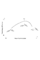
- FIG. 4 is an explanatory diagram for explaining the relationship between the flow rate of the exhaust gas supplied to the variable capacity turbine and the efficiency of the supercharger.
- the relationship between the flow rate of the exhaust gas and the efficiency of the turbocharger 1 is shown in a graph in which the horizontal axis represents the flow rate of the exhaust gas supplied to the variable capacity turbine 2 and the vertical axis represents the efficiency of the turbocharger 1.
- a curve C1 and a schematic diagram showing the opening/closing state between the nozzle vanes 6 when the flow rate of the exhaust gas supplied to the variable capacity turbine 2 is low, when the efficiency is at peak, and when the flow rate is higher than the efficiency peak is shown.
- the supercharger 1 is configured so that the efficiency of the supercharger 1 reaches its peak when the flow rate of the exhaust gas supplied to the variable capacity turbine 2 is high.
- the nozzle vanes 6 adjacent in the circumferential direction of the turbine rotor 21 are closer to each other than when the flow rate is high. , and the channel cross-sectional area of the exhaust gas channel 40 is small.
- each of the nozzle vanes 6 takes a posture along the circumferential direction, so that the inflow angle of the exhaust gas passing between the nozzle vanes 6 into the turbine rotor 21 is along the circumferential direction.
- the angle of inflow into the turbine rotor 21 is not uniform in the span direction, and the inflow angle on the hub side and the shroud side differs from that in the central portion in the span direction due to clearances formed therebetween.
- FIG. 5 is an explanatory diagram for explaining the exhaust gas flow in the vicinity of the trailing edge side of the turbine rotor of the variable capacity turbine according to the comparative example.
- FIG. 6 is an explanatory diagram for explaining the exhaust gas flow in the vicinity of the turbine rotor of the variable capacity turbine according to the comparative example.
- a hub-side flow path surface 44 in the variable capacity turbine 2 according to the comparative example is not formed with a groove portion 7 described later, and is flat over the entire surface.
- the angle at which the exhaust gas flows into the turbine rotor 21 is along the circumferential direction. Therefore, as shown in FIG.
- a large eddy current V may be generated in the vicinity.
- this large vortex V flows along the outer surface of the hub 211 toward the trailing edge 214 of the turbine rotor 21 . Flow loss may occur due to the swirl V, and the efficiency of the variable capacity turbine 2 may decrease.
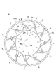
- FIG. 7 and 8 are schematic views of the exhaust gas flow path of the variable capacity turbine according to one embodiment, viewed from the turbine exit side in the axial direction.
- FIG. 7 shows a state in which the nozzle vanes are open at a high flow rate
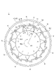
- FIG. 8 is a schematic diagram showing a state in which the nozzle vanes are closed at a low flow rate.
- FIG. 8 when the nozzle vanes 6 are closed, a gap is formed between the adjacent nozzle vanes 6 in the circumferential direction of the turbine rotor 21, and the exhaust gas passes through this gap.
- the first plate member 41 extends from an inner peripheral edge 431 of the first plate portion 43 to an outer peripheral edge 431 of the first plate portion 43 on the hub-side channel surface 44 facing the exhaust gas channel 40 .
- At least one laterally extending groove 7 is formed.
- the same number of grooves 7 as the nozzle vanes 6 are formed in the hub-side flow path surface 44 .
- At least a part of each of the plurality of grooves 7 is positioned between the rotation centers RC of the nozzle vanes 6 adjacent in the circumferential direction of the turbine rotor 21 .
- the outer peripheral end 74 of each of the plurality of grooves 7 is located radially inside the rotation center RC.
- the variable capacity turbine 2 according to some embodiments, as shown in FIG. 40, and a variable nozzle unit 5 including a plurality of nozzle vanes 6 described above.
- the exhaust gas flow path forming portion 4 includes a first plate-like member 41 having the above-described annular first plate portion 43 and a second plate-like member having the above-described annular second plate portion 45. a member 42; As shown in FIGS. 7 and 8 , the first plate-like member 41 extends from the inner peripheral edge 431 of the first plate portion 43 to the outer peripheral edge 43 of the first plate portion 43 on the hub-side channel surface 44 facing the exhaust gas channel 40 . At least one laterally extending groove 7 is formed.
- the groove portion 7 formed in the hub-side flow passage surface 44 extends outward from the inner peripheral edge 431 of the first plate portion 43 , so that the exhaust gas flowing into the groove portion 7 is discharged from the groove portion 7 . It can lead directly to the turbine rotor 21 .
- the exhaust gas flowing through the groove portion 7 is guided by the wall surface (first wall surface 71) of the groove portion 7, so that the inflow angle to the turbine rotor 21 is corrected to the angle along the wall surface.
- the inflow angle (inclination angle with respect to the radial direction) of the exhaust gas flowing on the hub side to the front edge 213 of the turbine rotor 21 when the flow rate is low can be maintained at a predetermined angle (fixed value ⁇ ).
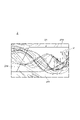
- FIG. 9 is an explanatory diagram for explaining the exhaust gas flow in the vicinity of the trailing edge side of the turbine rotor of the variable capacity turbine according to one embodiment.
- FIG. 10 is an explanatory diagram for explaining the exhaust gas flow in the vicinity of the turbine rotor of the variable capacity turbine according to one embodiment.
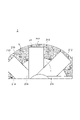
- FIG. 11 is a schematic view of the exhaust gas flow path of the variable capacity turbine according to the embodiment as viewed from the turbine exit side in the axial direction, and is a schematic view showing an enlarged vicinity of the groove portion.
- the plurality of nozzle vanes 6 includes an upstream nozzle vane 6A that is adjacent to one of the plurality of grooves 7 on the upstream side in the rotational direction RD of the turbine rotor 21, and an upstream nozzle vane 6A. and a downstream nozzle vane 6 ⁇ /b>B adjacent to one groove 7 on the downstream side in the rotational direction RD of the turbine rotor 21 .
- Each of the plurality of grooves 7 has a first wall surface 71 and a second wall surface 72 extending from the hub-side flow path surface 44 of the first plate portion 43 toward the opposite rear surface 412 , and the first wall surface 71 and the second wall surface 72 . and a third wall surface (bottom surface) 73 that connects the
- At least one groove portion 7 described above is located downstream of an outer peripheral end 74 of the groove portion 7 and the outer peripheral end 74 in the rotational direction RD of the turbine rotor 21 . It includes a first wall surface 71 connecting the downstream end 711 on the inner peripheral edge 431 of the groove portion 7 .
- the exhaust gas flowing through the groove portion 7 is guided by the first wall surface 71 and corrected to an angle along the first wall surface 71 . Due to the first wall surface 71, the inflow angle (inclination angle with respect to the radial direction of the turbine rotor 21) of the exhaust gas flowing on the hub side to the front edge 213 of the turbine rotor 21 when the flow rate is low can be maintained at a predetermined angle (fixed value ⁇ ). Since the first wall surface 71 connects the outer peripheral end 74 of the groove portion 7 and the downstream end 711 on the inner peripheral edge 431 of the groove portion 7 , the flow direction of the exhaust gas can be adjusted without hindering the flow of the exhaust gas flowing through the groove portion 7 . can be fixed.
- the above-described first wall surface 71 is formed between the outer peripheral end 74 of the groove portion 7 and the downstream end on the inner peripheral edge 431 in plan view perpendicular to the axis LA of the turbine rotor 21 . 711 and 711 in a straight line, and includes a convex curved surface 71A protruding downstream in the rotation direction RD.
- the first wall surface 71 includes the convex curved surface 71A projecting downstream in the rotation direction RD of the turbine rotor 21, so that the exhaust gas flowing through the groove portion 7 can be gently guided.
- separation of the exhaust gas from the first wall surface 71 can be suppressed, so that the flow direction of the exhaust gas can be corrected without the first wall surface 71 hindering the flow of the exhaust gas.
- the above-described convex surface 71A has an inclination angle of the tangent line TL of the convex surface 71A in a plan view orthogonal to the axis LA of the turbine rotor 21 with respect to the radial direction of the turbine rotor 21.
- ⁇ is inclined so as to decrease toward the downstream end 711 side.
- the inclination angle ⁇ becomes a minimum angle ⁇ .
- the inflow angle of the exhaust gas flowing along the convex curved surface 71A into the turbine rotor 21 also becomes the angle ⁇ .
- the convex curved surface 71A is such that the inclination angle ⁇ of the tangent line TL of the convex curved surface 71A in a plan view perpendicular to the axis LA of the turbine rotor 21 with respect to the radial direction of the turbine rotor 21 increases toward the downstream end 711 side. Since it is inclined to be small, separation of the exhaust gas from the convex curved surface 71A is suppressed, and the inflow angle (angle of inclination with respect to the radial direction) of the exhaust gas flowing along the convex curved surface 71A into the turbine rotor 21 is made small. can be fixed.
- the above-described plurality of nozzle vanes 6 are downstream adjacent to the above-described at least one groove portion 7 in the rotational direction RD of the turbine rotor 21 .
- the hub-side flow path surface 44 of the first plate-shaped member 41 described above is formed by the first wall surface 71 of the groove portion 7 in the rotation direction RD of the turbine rotor 21 and the downstream nozzle vane 6B. and an area A1 in which the groove portion 7 is not formed.
- the rotation region RA1 of the downstream nozzle vane 6B is the range in which the downstream nozzle vane 6B exists from the state in which the downstream nozzle vane 6B is open (see FIG. 7) to the state in which it is closed (see FIG. 8). is projected onto the hub-side flow passage surface 44 of the first plate portion 43 in FIG. The groove portion 7 is not formed in the rotation area RA1.
- the hub-side flow passage surface 44 has the region A1 where the groove portion 7 is not formed between the first wall surface 71 and the rotation region RA1 of the downstream nozzle vane 6B.
- An increase in the clearance between the flow path surface 44 and the hub-side end 61 of the downstream nozzle vane 6B can be suppressed, and an increase in flow loss of the exhaust gas due to the increase in the clearance can be suppressed.
- the hub-side flow path surface 44 has an area A1 in which the groove portion 7 is not formed between the first wall surface 71 and the rotation area RA1 of the downstream nozzle vane 6B, thereby setting the shape of the first wall surface 71. The degree of freedom in the shape of the first wall surface 71 can be increased.
- At least one groove portion 7 described above is positioned upstream of the outer peripheral end 74 of the groove portion 7 and the outer peripheral end 74 in the rotational direction RD of the turbine rotor 21 . It further includes a second wall surface 72 connecting the upstream end 721 on the inner peripheral edge 431 of the groove portion 7 .
- the second wall surface 72 linearly connects the outer peripheral end 74 and the upstream end 721 in a plan view perpendicular to the axis LA of the turbine rotor 21 . and may be connected in a curved line.
- the groove portion 7 includes the first wall surface 71 connecting the outer peripheral end 74 of the groove portion 7 and the downstream end 711 on the inner peripheral edge 431 of the groove portion 7, the outer peripheral end 74 of the groove portion 7 and the inner peripheral edge of the groove portion 7. and a second wall surface 72 connecting with an upstream end 721 on 431 .
- the area (projected area) of the groove 7 in plan view perpendicular to the axis LA of the turbine rotor 21 can be increased, so that a large amount of exhaust gas can flow into the groove 7 .
- the flow direction of a large amount of exhaust gas in the groove portion 7 can be corrected by the groove portion 7, the flow of the exhaust gas flowing on the hub side can be effectively corrected when the flow rate is low.
- the plurality of nozzle vanes 6 described above are adjacent to the at least one groove portion 7 described above on the upstream side in the rotational direction RD of the turbine rotor 21 .
- the hub-side flow path surface 44 of the first plate-like member 41 described above is formed by the second wall surface 72 of the groove portion 7 in the rotational direction RD of the turbine rotor 21 and the upstream nozzle vane 6A. and an area A2 in which the groove portion 7 is not formed.
- the rotation area RA2 of the upstream nozzle vane 6A is the range in which the upstream nozzle vane 6A exists from the state in which the upstream nozzle vane 6A is open (see FIG. 7) to the state in which it is closed (see FIG. 8). is projected onto the hub-side flow passage surface 44 of the first plate portion 43 in FIG. The groove portion 7 is not formed in the rotation area RA2.
- the hub-side flow path surface 44 has the area A2 where the groove 7 is not formed between the second wall surface 72 and the rotation area RA2 of the upstream nozzle vane 6A.
- An increase in the clearance between the flow path surface 44 and the hub-side end 61 of the upstream nozzle vane 6A can be suppressed, and an increase in flow loss of the exhaust gas due to the increase in the clearance can be suppressed.
- FIG. 12 is a schematic cross-sectional view schematically showing a cross section along the axial direction of the turbine rotor of the first plate member in the variable capacity turbine according to one embodiment.
- FIG. 12 schematically shows a cross section of the first plate-like member 41 taken along the line AB shown in FIG. 7, viewed from the upstream side in the rotation direction RD. Also, the shape of the groove portion 7 in the CD cross section shown in FIG. 7 is indicated by the dotted line in FIG.
- the hub-side flow path surface 44 described above includes a flat surface 44A extending along the radial direction of the turbine rotor 21 .
- At least one groove portion 7 described above is configured such that the depth from the flat surface 44A increases toward the inner peripheral side of the first plate portion 43 .
- the groove portion 7 is configured so that the depth from the flat surface 44A increases toward the inner peripheral side of the first plate portion 43, so that the exhaust gas flowing along the flat surface 44A flows into the groove portion 7. Easier to get inside. Further, the wall surface (the third wall surface 73 ) of the groove portion 7 gently guides the exhaust gas flowing through the groove portion 7 toward the inner peripheral side and guides it to the turbine rotor 21 . As a result, it is possible to suppress the occurrence of turbulence in the flow of the exhaust gas flowing on the hub side and the exhaust gas flowing in the groove portion 7 when the flow rate is low.
- the at least one groove portion 7 described above extends along a direction intersecting the flat surface 44A in plan view along the axis LA of the turbine rotor 21 as shown in FIG.
- An inclined surface 73A that satisfies the condition of 0° ⁇ 15° with respect to an imaginary extension surface 44B obtained by extending the flat surface 44A.
- the exhaust gas may separate from the inclined surface 73A and the inclined surface 73A may become unable to guide the exhaust gas.
- the inclination angle ⁇ of the inclined surface 73A By setting the inclination angle ⁇ of the inclined surface 73A to satisfy the above conditions, separation of the exhaust gas from the inclined surface 73A can be suppressed, so that the exhaust gas flowing through the groove portion 7 can be guided to the inner peripheral side by the inclined surface 73A.
- the hub-side flow path surface 44 described above includes a flat surface 44A extending along the radial direction of the turbine rotor 21 .
- the at least one groove portion 7 described above satisfies 0 ⁇ T1 ⁇ 0.2T, where T is the thickness of the first plate portion 43 and T1 is the maximum depth of the at least one groove portion 7 from the flat surface 44A. is configured to meet
- the groove portion 7 has the maximum depth from the flat surface 44A at the inner peripheral edge 431 . If the groove portion 7 is too deep (that is, the maximum depth T1 is too large), the flow toward the back surface of the turbine rotor 21 increases, and the thrust force applied to the turbine rotor 21 may change.
- the groove portion 7 is preferably configured to satisfy the condition 0 ⁇ T1 ⁇ 0.1T.
- the maximum depth T1 of the groove portion 7 from the flat surface 44A is too large, the amount of exhaust gas flowing into the groove portion 7 increases, the flow of the main stream in the exhaust gas passage 40 is hindered, and the exhaust gas flows. Flow losses may increase.
- the maximum depth T1 it is possible to prevent the flow of the main flow in the exhaust gas flow path 40 from being obstructed by the groove portion 7, and to prevent the efficiency of the turbine 2 from being lowered.
- a turbocharger 1 includes the above-described variable capacity turbine 2 and a centrifugal compressor 3 configured to be driven by the variable capacity turbine 2, as shown in FIG. .
- the vortex V generated in the vicinity of the leading edge 213 of the hub 211 of the turbine rotor 21 at the time of low flow can be reduced. Efficiency can be improved.
- a variable capacity turbine (2) according to at least one embodiment of the present disclosure, a turbine rotor (21); a scroll passage forming portion (26) for forming a scroll passage (25) on the outer peripheral side of the turbine rotor (21); an exhaust gas passage forming portion (4) forming an exhaust gas passage (40) for guiding exhaust gas from the scroll passage (25) to the turbine rotor (21); A variable nozzle unit (5) for adjusting the flow of the exhaust gas in the exhaust gas channel (40), the variable nozzle unit (5) being arranged in the exhaust gas channel (40) and configured to be rotatable around each rotation center.
- a variable nozzle unit (5) comprising a plurality of nozzle vanes (6) with
- the exhaust gas flow path forming portion (4) is a first plate member (41) having an annular first plate portion (43); An annular second plate portion (45) defining the exhaust gas flow path (40) between itself and the first plate portion (43), wherein the first plate portion (45) extends along the axial direction of the turbine rotor (21). a second plate member (42) having a second plate portion (45) arranged closer to the turbine exit side than (43);
- the first plate-like member (41) is provided on the inner peripheral edge (43) of the first plate (43) on the hub-side channel surface (44) facing the exhaust gas channel (40). 431) was formed with at least one groove (7) extending to the outer peripheral side.
- the groove portion (7) formed in the hub-side flow passage surface (44) extends outward from the inner peripheral edge (431) of the first plate portion (43). 7)
- the exhaust gas that has flowed into the groove portion (7) can be directly guided from the inside of the groove portion (7) to the turbine rotor (21).
- the exhaust gas flowing through the groove (7) is guided by the wall surface (first wall surface 71) of the groove (7), so that the inflow angle to the turbine rotor (21) is corrected to the angle along the wall surface.
- the inflow angle (inclination angle with respect to the radial direction) of the exhaust gas flowing on the hub side to the front edge (213) of the turbine rotor (21) at a low flow rate can be maintained at a predetermined angle (fixed value ⁇ ).
- a predetermined angle fixed value ⁇
- the loss of the turbine rotor (21) due to the vortex can be reduced, so the efficiency of the turbine (2) can be improved at low flow rates.
- variable capacity turbine (2) of 1) above wherein Said at least one groove (7) is on the outer peripheral edge (74) of the groove (7) and the inner peripheral edge (431) of the groove (7) located downstream of the outer peripheral edge (74) in the rotational direction of the turbine rotor (21) It includes a first wall surface (71) connecting the downstream end (711).
- the exhaust gas flowing in the groove (7) is guided by the first wall surface (71) and corrected to an angle along the first wall surface (71).
- the first wall surface (71) maintains the inflow angle (inclination angle with respect to the radial direction) of the exhaust gas flowing on the hub side to the leading edge (213) of the turbine rotor (21) at a predetermined angle (fixed value ⁇ ) when the flow rate is low. can. Since the first wall surface (71) connects the outer peripheral end (74) of the groove (7) and the downstream end (711) on the inner peripheral edge (431) of the groove (7), the inside of the groove (7) The flow direction of the exhaust gas can be corrected without disturbing the flow of the flowing exhaust gas.
- variable capacity turbine (2) of 2) above wherein
- the first wall surface (71) is In a plan view orthogonal to the axis of the turbine rotor (21), an imaginary line connecting the outer peripheral end (74) of the groove (7) and the downstream end (711) on the inner peripheral edge (431) It includes a convex curved surface (71A) projecting downstream in the direction of rotation with respect to the line (IL).
- the first wall surface (71) includes a convex curved surface (71A) protruding downstream in the rotational direction of the turbine rotor (21). can guide you to As a result, separation of the exhaust gas from the first wall surface (71) can be suppressed, so that the flow direction of the exhaust gas can be corrected without the first wall surface (71) hindering the flow of the exhaust gas.
- variable capacity turbine (2) of 3) above wherein
- the convex curved surface (71A) has an angle of inclination of a tangent line (TL) of the convex curved surface (71A) in plan view perpendicular to the axis of the turbine rotor (21) with respect to the radial direction of the turbine rotor (21). It is inclined so that it becomes smaller toward the end (711) side.
- the convex curved surface (71A) is inclined with respect to the radial direction of the turbine rotor (21) by the tangent line (TL) of the convex curved surface (71A) in plan view orthogonal to the axis of the turbine rotor (21). Since the angle is inclined to become smaller toward the downstream end side, the turbine rotor (21) for the exhaust gas flowing along the convex curved surface (71A) while suppressing separation of the exhaust gas from the convex curved surface (71A). It is possible to correct the inflow angle (tilt angle with respect to the radial direction) to a small one.
- the hub-side flow path surface (44) of the first plate member (41) is In a plan view orthogonal to the axis of the turbine rotor (21), the first wall surface (71) of the groove (7) in the rotational direction of the turbine rotor (21) and the rotation of the downstream nozzle vane (6B). It has an active area (RA1) and an area (A1) in which the groove (7) is not formed.
- the hub-side flow path surface (44) has the groove (7) formed between the first wall surface (71) and the rotation area (RA1) of the downstream nozzle vane (6B). Since the groove portion (7) has the region (A1) where there is no air flow, it is possible to suppress an increase in the clearance between the hub-side flow path surface (44) and the hub-side end (61) of the downstream nozzle vane (6B). It is possible to suppress an increase in the flow loss of the exhaust gas due to the increase. Further, the hub-side flow path surface (44) has an area (A1) where the groove (7) is not formed between the first wall surface (71) and the rotation area (RA1) of the downstream nozzle vane (6B). Therefore, when setting the shape of the first wall surface (71), it is not necessary to consider the rotation area (RA1) of the downstream nozzle vane (6B), so the degree of freedom of the shape of the first wall surface (71) is can increase
- variable capacity turbine (2) of any one of 2) to 5) above wherein Said at least one groove (7) is on the outer peripheral edge (74) of the groove (7) and the inner peripheral edge (431) of the groove (7) located upstream in the rotational direction of the turbine rotor (21) from the outer peripheral edge (74); It further includes a second wall surface (72) connecting the upstream end (721).
- the groove (7) has a first wall surface ( 71) and a second wall surface (72) connecting the outer peripheral edge (74) of the groove (7) and the upstream edge (721) on the inner peripheral edge (431) of the groove (7).
- the area (projected area) of the groove (7) in plan view perpendicular to the axis of the turbine rotor (21) can be increased, so that a large amount of exhaust gas can flow into the groove (7). .
- the flow direction of a large amount of exhaust gas in the groove portion (7) can be corrected by the groove portion (7), the flow of the exhaust gas flowing on the hub side can be effectively corrected when the flow rate is low.
- variable capacity turbine (2) of 6) wherein
- the plurality of nozzle vanes (6) includes an upstream nozzle vane (6A) adjacent to the at least one groove (7) on the upstream side in the rotational direction of the turbine rotor (21);
- the hub-side flow path surface (44) of the first plate member (41) is In a plan view orthogonal to the axis of the turbine rotor (21), the second wall surface (72) of the groove (7) in the rotational direction of the turbine rotor (21) and the rotation of the upstream nozzle vane (6A) It has an active area (RA2) and an area (A2) where the groove (7) is not formed therebetween.
- the hub-side flow path surface (44) has the groove (7) formed between the second wall surface (72) and the rotation area (RA2) of the upstream nozzle vane (6A). Since the groove portion (7) has the region (A2) where there is no air flow, it is possible to suppress an increase in the clearance between the hub-side flow path surface (44) and the hub-side end (61) of the upstream nozzle vane (6A). It is possible to suppress an increase in the flow loss of the exhaust gas due to the increase.
- variable capacity turbine (2) of any one of 1) to 7) above, wherein
- the hub-side flow path surface (44) includes a flat surface (44A) extending along the radial direction of the turbine rotor (21),
- the at least one groove portion (7) is configured such that the depth from the flat surface (44A) increases toward the inner peripheral side of the first plate portion (43).
- the depth of the groove portion (7) from the flat surface (44A) increases toward the inner peripheral side of the first plate portion (43), so that the flat surface ( 44A) becomes easier to flow into the groove (7).
- the wall surface (third wall surface 73) of the groove (7) gently guides the exhaust gas flowing through the groove (7) to the inner peripheral side and guides it to the turbine rotor (21). As a result, it is possible to suppress the occurrence of turbulence in the flow of the exhaust gas flowing on the hub side and the exhaust gas flowing in the groove portion (7) when the flow rate is low.
- variable capacity turbine (2) of 8) above, Said at least one groove (7) is In a plan view along the axis of the turbine rotor (21), an inclined surface (73A) extending along a direction intersecting the flat surface (44A) and extending the flat surface (44A) An inclined surface (73A) satisfying the condition of 0° ⁇ 15° is included.
- variable capacity turbine (2) of any one of 1) to 9) above, wherein
- the hub-side flow path surface (44) includes a flat surface (44A) extending along the radial direction of the turbine rotor (21),
- the at least one groove portion (7) is , 0 ⁇ T1 ⁇ 0.2T.
- the maximum depth T1 of the groove (7) from the flat surface (44A) is too large, the amount of exhaust gas flowing into the groove (7) increases, and the exhaust gas flow path (40) increases. The flow of the main flow in the is obstructed, and there is a risk that the flow loss of the exhaust gas increases.
- the maximum depth (T1) so as to satisfy the above conditions, it is possible to suppress the obstruction of the main stream flow in the exhaust gas flow path (40) by the groove (7), thereby reducing the efficiency of the turbine (2). can be suppressed.
- a turbocharger (1) according to at least one embodiment of the present disclosure, A variable capacity turbine (2) according to any one of 1) to 10) above; a centrifugal compressor (3) configured to be driven by the variable capacity turbine (2).
Landscapes
- Engineering & Computer Science (AREA)
- Mechanical Engineering (AREA)
- General Engineering & Computer Science (AREA)
- Chemical & Material Sciences (AREA)
- Combustion & Propulsion (AREA)
- Supercharger (AREA)
- Control Of Turbines (AREA)
Abstract
Priority Applications (3)
| Application Number | Priority Date | Filing Date | Title |
|---|---|---|---|
| US18/272,700 US12158073B2 (en) | 2021-01-21 | 2021-12-13 | Variable geometry turbine and turbocharger |
| CN202180090662.0A CN116761933B (zh) | 2021-01-21 | 2021-12-13 | 可变容量涡轮及增压器 |
| DE112021005961.0T DE112021005961T5 (de) | 2021-01-21 | 2021-12-13 | Turbine mit variabler geometrie und turbolader |
Applications Claiming Priority (2)
| Application Number | Priority Date | Filing Date | Title |
|---|---|---|---|
| JP2021008190A JP7444799B2 (ja) | 2021-01-21 | 2021-01-21 | 可変容量タービンおよび過給機 |
| JP2021-008190 | 2021-01-21 |
Publications (1)
| Publication Number | Publication Date |
|---|---|
| WO2022158167A1 true WO2022158167A1 (fr) | 2022-07-28 |
Family
ID=82548333
Family Applications (1)
| Application Number | Title | Priority Date | Filing Date |
|---|---|---|---|
| PCT/JP2021/045835 Ceased WO2022158167A1 (fr) | 2021-01-21 | 2021-12-13 | Turbine à capacité variable et compresseur de suralimentation |
Country Status (5)
| Country | Link |
|---|---|
| US (1) | US12158073B2 (fr) |
| JP (1) | JP7444799B2 (fr) |
| CN (1) | CN116761933B (fr) |
| DE (1) | DE112021005961T5 (fr) |
| WO (1) | WO2022158167A1 (fr) |
Families Citing this family (2)
| Publication number | Priority date | Publication date | Assignee | Title |
|---|---|---|---|---|
| CN119053772A (zh) * | 2022-05-25 | 2024-11-29 | 株式会社Ihi | 涡轮机以及增压器 |
| DE102024127618A1 (de) * | 2024-09-24 | 2026-03-26 | Borgwarner Inc. | Leiteinrichtung für eine turbine |
Citations (3)
| Publication number | Priority date | Publication date | Assignee | Title |
|---|---|---|---|---|
| JP2005299660A (ja) * | 2004-04-08 | 2005-10-27 | Holset Eng Co Ltd | 可変形態タービン |
| US20160146100A1 (en) * | 2014-11-21 | 2016-05-26 | Ford Global Technologies, Llc | Systems and methods for a variable geometry turbine nozzle |
| JP2020165374A (ja) * | 2019-03-29 | 2020-10-08 | 株式会社Ihi | タービンおよび過給機 |
Family Cites Families (11)
| Publication number | Priority date | Publication date | Assignee | Title |
|---|---|---|---|---|
| US4355953A (en) * | 1980-04-07 | 1982-10-26 | Guy F. Atkinson Company | Flow-adjusted hydraulic rotary machine |
| DE19805476C1 (de) * | 1998-02-11 | 1999-10-07 | Daimler Chrysler Ag | Abgasturbolader für eine Brennkraftmaschine |
| EP2351920B1 (fr) * | 2008-11-05 | 2016-04-13 | IHI Corporation | Turbocompresseur |
| JP5402548B2 (ja) | 2009-11-12 | 2014-01-29 | トヨタ自動車株式会社 | 可変容量型過給機 |
| US9267427B2 (en) * | 2013-06-11 | 2016-02-23 | Ford Global Technologies, Llc | Variable geometry turbine vane |
| US9845810B2 (en) * | 2014-06-24 | 2017-12-19 | Concepts Nrec, Llc | Flow control structures for turbomachines and methods of designing the same |
| WO2017109995A1 (fr) * | 2015-12-25 | 2017-06-29 | 三菱重工業株式会社 | Mécanisme à buse variable et turbocompresseur à géométrie variable |
| US10731503B2 (en) * | 2016-03-30 | 2020-08-04 | Mitsubishi Heavy Industries Engine & Turbocharger, Ltd. | Turbocharger |
| JP2018053800A (ja) | 2016-09-29 | 2018-04-05 | 株式会社豊田自動織機 | ターボチャージャ |
| JP2019167844A (ja) | 2018-03-22 | 2019-10-03 | 株式会社豊田自動織機 | 可変ノズルターボチャージャー |
| JP7146703B2 (ja) | 2019-06-28 | 2022-10-04 | 株式会社クボタ | 作業機 |
-
2021
- 2021-01-21 JP JP2021008190A patent/JP7444799B2/ja active Active
- 2021-12-13 US US18/272,700 patent/US12158073B2/en active Active
- 2021-12-13 WO PCT/JP2021/045835 patent/WO2022158167A1/fr not_active Ceased
- 2021-12-13 DE DE112021005961.0T patent/DE112021005961T5/de active Pending
- 2021-12-13 CN CN202180090662.0A patent/CN116761933B/zh active Active
Patent Citations (3)
| Publication number | Priority date | Publication date | Assignee | Title |
|---|---|---|---|---|
| JP2005299660A (ja) * | 2004-04-08 | 2005-10-27 | Holset Eng Co Ltd | 可変形態タービン |
| US20160146100A1 (en) * | 2014-11-21 | 2016-05-26 | Ford Global Technologies, Llc | Systems and methods for a variable geometry turbine nozzle |
| JP2020165374A (ja) * | 2019-03-29 | 2020-10-08 | 株式会社Ihi | タービンおよび過給機 |
Also Published As
| Publication number | Publication date |
|---|---|
| DE112021005961T5 (de) | 2023-09-14 |
| CN116761933A (zh) | 2023-09-15 |
| US20240076996A1 (en) | 2024-03-07 |
| JP7444799B2 (ja) | 2024-03-06 |
| JP2022112371A (ja) | 2022-08-02 |
| CN116761933B (zh) | 2026-04-21 |
| US12158073B2 (en) | 2024-12-03 |
Similar Documents
| Publication | Publication Date | Title |
|---|---|---|
| CN107816440B (zh) | 离心压缩机 | |
| US9771856B2 (en) | Centrifugal compressor | |
| CN113217469A (zh) | 压缩机壳体、具备该压缩机壳体的压缩机以及具备该压缩机的涡轮增压机 | |
| CN103026005B (zh) | 可变容量涡轮 | |
| WO2018146753A1 (fr) | Compresseur centrifuge et turbocompresseur | |
| WO2022158167A1 (fr) | Turbine à capacité variable et compresseur de suralimentation | |
| US11821339B2 (en) | Turbocharger | |
| JP6959992B2 (ja) | タービン及びターボチャージャ | |
| CN111448374B (zh) | 涡轮及涡轮增压器 | |
| JP7123029B2 (ja) | 遠心圧縮機 | |
| CN118176365A (zh) | 离心压缩机的叶轮、离心压缩机以及涡轮增压器 | |
| US12158099B2 (en) | Turbine and turbocharger | |
| JP7423557B2 (ja) | 可変容量タービンおよび過給機 | |
| US12180848B2 (en) | Centrifugal compressor and turbocharger | |
| JP7808692B2 (ja) | 遠心圧縮機のケーシング、遠心圧縮機及びターボチャージャ | |
| JP7749509B2 (ja) | タービンハウジングおよび可変容量型のターボチャージャ | |
| WO2020188763A1 (fr) | Compresseur centrifuge et turbocompresseur de suralimentation | |
| JP2023000817A (ja) | ターボチャージャ | |
| WO2022196234A1 (fr) | Turbine et compresseur de suralimentation | |
| JP2023023914A (ja) | 遠心圧縮機 | |
| JP2023118180A (ja) | タービン及び過給機 | |
| CN113423929A (zh) | 喷嘴叶片 |
Legal Events
| Date | Code | Title | Description |
|---|---|---|---|
| 121 | Ep: the epo has been informed by wipo that ep was designated in this application |
Ref document number: 21921269 Country of ref document: EP Kind code of ref document: A1 |
|
| WWE | Wipo information: entry into national phase |
Ref document number: 112021005961 Country of ref document: DE |
|
| WWE | Wipo information: entry into national phase |
Ref document number: 202180090662.0 Country of ref document: CN |
|
| WWE | Wipo information: entry into national phase |
Ref document number: 18272700 Country of ref document: US |
|
| 122 | Ep: pct application non-entry in european phase |
Ref document number: 21921269 Country of ref document: EP Kind code of ref document: A1 |