WO2022158255A1 - 情報処理装置、および移動装置、並びに情報処理システム - Google Patents
情報処理装置、および移動装置、並びに情報処理システム Download PDFInfo
- Publication number
- WO2022158255A1 WO2022158255A1 PCT/JP2021/048264 JP2021048264W WO2022158255A1 WO 2022158255 A1 WO2022158255 A1 WO 2022158255A1 JP 2021048264 W JP2021048264 W JP 2021048264W WO 2022158255 A1 WO2022158255 A1 WO 2022158255A1
- Authority
- WO
- WIPO (PCT)
- Prior art keywords
- area
- stage
- map
- data
- potential map
- Prior art date
- Legal status (The legal status is an assumption and is not a legal conclusion. Google has not performed a legal analysis and makes no representation as to the accuracy of the status listed.)
- Ceased
Links
Images













Classifications
-
- G—PHYSICS
- G01—MEASURING; TESTING
- G01C—MEASURING DISTANCES, LEVELS OR BEARINGS; SURVEYING; NAVIGATION; GYROSCOPIC INSTRUMENTS; PHOTOGRAMMETRY OR VIDEOGRAMMETRY
- G01C21/00—Navigation; Navigational instruments not provided for in groups G01C1/00 - G01C19/00
- G01C21/20—Instruments for performing navigational calculations
- G01C21/206—Instruments for performing navigational calculations specially adapted for indoor navigation
-
- G—PHYSICS
- G01—MEASURING; TESTING
- G01C—MEASURING DISTANCES, LEVELS OR BEARINGS; SURVEYING; NAVIGATION; GYROSCOPIC INSTRUMENTS; PHOTOGRAMMETRY OR VIDEOGRAMMETRY
- G01C21/00—Navigation; Navigational instruments not provided for in groups G01C1/00 - G01C19/00
- G01C21/38—Electronic maps specially adapted for navigation; Updating thereof
- G01C21/3804—Creation or updating of map data
- G01C21/3833—Creation or updating of map data characterised by the source of data
- G01C21/3837—Data obtained from a single source
-
- G—PHYSICS
- G01—MEASURING; TESTING
- G01C—MEASURING DISTANCES, LEVELS OR BEARINGS; SURVEYING; NAVIGATION; GYROSCOPIC INSTRUMENTS; PHOTOGRAMMETRY OR VIDEOGRAMMETRY
- G01C21/00—Navigation; Navigational instruments not provided for in groups G01C1/00 - G01C19/00
- G01C21/005—Navigation; Navigational instruments not provided for in groups G01C1/00 - G01C19/00 with correlation of navigation data from several sources, e.g. map or contour matching
-
- G—PHYSICS
- G05—CONTROLLING; REGULATING
- G05D—SYSTEMS FOR CONTROLLING OR REGULATING NON-ELECTRIC VARIABLES
- G05D1/00—Control of position, course, altitude or attitude of land, water, air or space vehicles, e.g. using automatic pilots
- G05D1/02—Control of position or course in two dimensions
Definitions
- the present disclosure relates to information processing devices, mobile devices, and information processing systems. More specifically, in a configuration where a performance such as a performer's song performed on the stage is filmed with a camera attached to a moving device (automatic traveling robot) that moves on the stage, it collides with an object such as a performer or a speaker on the stage.
- the present invention relates to an information processing device, a moving device, and an information processing system that generate a map that sets a route that does not interfere with the line of sight of spectators, and controls movement according to the map.
- the camera When performing such image capturing, the camera is mounted on a moving device (cart) such as an automatic traveling robot, moves to various positions on the stage, and captures images from various angles.
- a moving device such as an automatic traveling robot
- Patent Document 1 Japanese Unexamined Patent Application Publication No. 2020-087061
- Patent Document 2 Patent No. 5160322
- Patent Document 1 discloses an unmanned mobile body that monitors a person so as not to interfere with the person to be monitored. Specifically, it is a configuration in which a region in which a moving object is difficult to be sensed by the sensory organs of a person to be monitored is determined, and monitoring is performed from the determined region.
- Patent Document 2 discloses a robot device that follows a certain object, and even if an obstacle enters between the object to be followed and the robot and the robot is about to lose sight of the object to be followed, the robot continues the following process.
- An enabling configuration is disclosed.
- Patent Document 1 selects an area to be monitored that is difficult for a human to perceive, and monitors from the selected position. , each merely disclosing a configuration for achieving a particular purpose.
- Patent Documents 1 and 2 do not disclose a control configuration for determining the optimum route for moving the camera in consideration of such various situations.
- the present disclosure has been made, for example, in view of the above problems, and it is possible to optimize the camera according to various situations such as the movement position of the performer performing on the stage, the position of the equipment on the stage, and the line of sight of the audience.
- the present invention provides an information processing device, a mobile device, and an information processing system that determine a suitable position and travel route and control the movement of a mobile device (camera).
- a first aspect of the present disclosure includes: having a data processing unit that generates a potential map that defines a travel allowable area of an image capturing robot that moves on a stage and captures an image;
- the data processing unit Acquiring at least one of action schedule data of the performer on the stage and arrangement schedule data of the object on the stage, and determining a probability of collision with the performer or the object on the stage based on the acquired data.
- An information processing device that generates a potential map that defines a permissible travel area below a value.
- a second aspect of the present disclosure is A map generated based on at least one of action schedule data of a performer on the stage and arrangement schedule data of an object on the stage, wherein the probability of collision with the performer or object on the stage is a specified threshold value.
- a storage unit that stores travel route information generated based on a potential map that defines the following permissible travel regions, or at least one of a communication unit that acquires the travel route information from an external device, The mobile device executes travel processing according to either the travel route information acquired from the storage unit or the travel route information acquired via the communication unit.
- a third aspect of the present disclosure is An information processing system having an image capturing robot and a server
- the image capturing robot is an image capturing robot that moves on a stage to capture an image
- the server is a data processing unit that generates a potential map that defines an allowable travel area of the imaging robot;
- the data processing unit Acquiring at least one of action schedule data of the performer on the stage and arrangement schedule data of the object on the stage, and determining a probability of collision with the performer or the object on the stage based on the acquired data.
- the imaging robot is An information processing system that travels along a travel route determined based on the potential map generated by the server.
- a system is a logical collective configuration of a plurality of devices, and the devices of each configuration are not limited to being in the same housing.
- a map for determining a safe running route that does not collide with performers and objects on the stage is generated, and the imaging robot is caused to travel along the route determined based on the map. becomes possible.
- a potential map is generated that defines an allowable travel area for an image capturing robot that moves on a stage to capture images.
- the data processing unit acquires the action schedule data of the performer on the stage, the arrangement schedule data of the object, and the lighting control schedule data on the stage, and based on the acquired data, an area that does not collide with the performer or the object and is not conspicuous due to lighting. is defined as the permissible travel area.
- the robot travel route is determined and the robot travels.
- the robot travel route is determined and the robot travels.
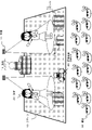
- FIG. 2 is a diagram illustrating an overview of a live stage and an overview of processing of the present disclosure
- FIG. FIG. 2 is a diagram illustrating an overview of a live stage and an overview of processing of the present disclosure
- FIG. FIG. 2 is a diagram illustrating an overview of a live stage and an overview of processing of the present disclosure
- FIG. It is a figure explaining the structure and process of the information processing apparatus of this indication. It is a figure explaining the structure and process of the information processing system of this indication.
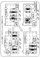
- FIG. 4 is a diagram illustrating an example of a performer-based potential map generated by an individual potential map generation unit
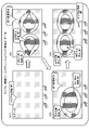
- FIG. 4 is a diagram illustrating an example of a lighting base potential map generated by an individual potential map generation unit
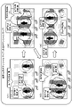
- FIG. 4 is a diagram illustrating an example of an object-based potential map generated by an individual potential map generation unit;
- FIG. 4 is a diagram illustrating an example of a pre-generated potential map generated by a potential map synthesizing unit; It is a figure explaining the structure and process of the information processing apparatus of this indication.
- FIG. 4 is a diagram illustrating an example of an imaging robot travel route determined based on a pre-generated potential map;
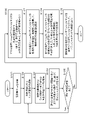
- FIG. 10 is a diagram showing a flowchart describing a performer-based potential map generation processing sequence executed by the information processing apparatus of the present disclosure;
- FIG. 10 is a diagram showing a flowchart describing a lighting-based potential map generation processing sequence executed by the information processing apparatus of the present disclosure;
- FIG. 10 is a diagram showing a flowchart describing a lighting-based potential map generation processing sequence executed by the information processing apparatus of the present disclosure
- FIG. 4 is a diagram showing a flowchart describing an object-based potential map generation processing sequence executed by the information processing apparatus of the present disclosure
- FIG. 5 is a diagram showing a flowchart describing a pre-generated potential map generation processing sequence executed by the information processing apparatus of the present disclosure
- FIG. 4 is a diagram describing an example of a simulation image generated by the information processing apparatus of the present disclosure
- FIG. 11 is a diagram illustrating processing in a second embodiment of the present disclosure
- FIG. FIG. 11 is a diagram illustrating processing in a second embodiment of the present disclosure
- FIG. 10 is a diagram illustrating a configuration example and processing of an information processing apparatus according to a second embodiment of the present disclosure
- FIG. 10 is a diagram illustrating an example of a priority spectator & TV camera base potential map generated by an information processing apparatus according to a second embodiment of the present disclosure
- FIG. 4 is a diagram showing a flowchart describing a processing sequence for generating a priority spectator & TV camera base potential map executed by the information processing apparatus of the present disclosure
- FIG. 12 is a diagram showing a flowchart describing a pre-generated potential map generation processing sequence executed by the information processing apparatus according to the second embodiment of the present disclosure
- FIG. 11 is a diagram illustrating a configuration example and processing of an information processing apparatus according to a third embodiment of the present disclosure
- FIG. 11 is a diagram illustrating the configuration and processing of an information processing system according to Example 3 of the present disclosure
- FIG. 11 is a diagram illustrating an example of a potential map generated by an information processing apparatus according to Example 3 of the present disclosure
- FIG. 11 is a diagram illustrating an example of a potential map generated by an information processing apparatus according to Example 3 of the present disclosure
- FIG. 12 is a diagram illustrating a flowchart describing a real-time data reflection potential map generation processing sequence executed by an information processing apparatus according to a third embodiment of the present disclosure
- FIG. 12 is a diagram illustrating a flowchart describing a real-time data reflection potential map generation processing sequence executed by an information processing apparatus according to a third embodiment of the present disclosure
- It is a figure explaining the hardware structural example of the information processing apparatus of this indication.
- FIG. 1 is a diagram showing an example of a performance such as a live music performance on a stage.
- the example shown in FIG. 1 is an example in which a performer 20 who is a duo of idol singers is performing live music on the stage 10 .
- a large number of spectators 30 are in front of the stage 10 and are watching the performance of the performers 20 .
- the image capturing robot 50 shown in FIG. 1 is a mobile device on which a camera is mounted, that is, a running robot, and moves around the stage to capture the performance of the performer 20 from various angles.
- the image capturing robot 50 is an automatic traveling robot (moving device) such as a trolley equipped with a camera, and captures images from various angles while traveling on the stage, for example, following a predetermined running route.
- moving device such as a trolley equipped with a camera
- the image capturing robot 50 needs to select a safe running route and move so as not to collide with the performers moving around on the stage and equipment such as microphones and speakers installed on the stage. In addition, it is also required to move so as not to interfere with the line of sight of the audience in front of the stage and surroundings.
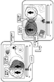
- speakers 12, monitors 13, and various decorative objects 14 are placed on a stage 10 where live performances are actually performed, and lighting 11 is also applied to performers 20 and the like.
- the performer 20 moves around the stage as the live performance progresses, and the position, brightness, and color of the lighting 11 change according to this movement. Also, the decoration objects 14 are replaced one after another according to the progress of the live performance.
- the stage state shown in FIG. 2 is a scene at time t1 during a live performance.
- the stage state at a certain time t2 after that for example, as shown in FIG. 3, the position of the performer 20 is changed, and the position, brightness, and color of the illumination 11 are also changed.
- the decoration object 14 is also replaced.
- the position of the performer 20 on the stage, the position, brightness and color of the lighting 11, the position of the decoration object, etc. are sequentially changed according to the time period during which the live performance is performed.
- the image capturing robot 50 needs to run so as not to collide with the performer 20, the decoration object 14 on the stage, the speaker 12, and other objects arranged thereon.
- the present disclosure determines the optimal camera position and travel route according to various situations such as the movement position of the performer performing on the stage, the position of the equipment on the stage, the lighting, the line of sight of the audience, etc. camera). Details of the configuration and processing of the present disclosure will be described below.
- FIG. 4 is a diagram illustrating a configuration example of the information processing apparatus 100 according to the first embodiment of the present disclosure.
- the information processing apparatus 100 may be configured inside the moving apparatus running on the stage shown in FIGS.
- a device that is independent of the image capturing robot 50 may be used.
- FIG. 5 shows a configuration example of an information processing system in which the information processing apparatus having the configuration shown in FIG. 4 is independent of the image capturing robot 50 .
- an information processing system 180 is constructed in which an information processing device (server) 100, a live venue information acquisition device 60, an image capturing robot 50 in the live venue, etc. are connected via a communication network. do.
- the information processing apparatus (server) 100 has the configuration shown in FIG.
- the live venue information acquisition device 60 is composed of a camera that captures images of the live venue, a microphone that acquires audio information of the live venue, an illuminance meter that detects lighting conditions, a color analysis device, etc., and acquires information such as the acquired image. , to the information processing apparatus (server) 100 via the communication network.
- the information processing device (server) 100 performs processing for generating a map (potential map) for determining the running route of the image capturing robot 50 in the live venue, determining the running route using the map, and determining the determined running route. Accordingly, processing for generating travel control information for the image capturing robot 50 and the like are performed.
- the information processing device (server) 100 further transmits the generated travel control information to the image capturing robot 50 via the communication network.
- the image capturing robot 50 runs on the stage according to the running control information received from the information processing device (server) 100 . For example, it is possible to perform processing using such an information processing system.
- the information processing device 100 has a storage unit 110 , an individual potential map generation unit 120 , a potential map synthesis unit 130 and a travel route generation unit 160 .
- the information processing apparatus 100 may be configured inside the moving apparatus that runs on the stage shown in FIGS. It may be a device independent of the image capturing robot 50, such as a device capable of communicating with the image capturing robot 50, like the information processing device (server) 100 shown.
- the storage unit 110 stores the following three data.
- A. performer action schedule data 111 B. stage lighting control schedule data 112
- these three scheduled data are data that are prepared in advance and stored in the storage unit 110 before the start of the live performance. That is, it is schedule data prepared in advance according to a program such as a live progress table prepared before the start of the live performance.
- the information processing apparatus 100 uses these schedule data to generate a map (potential map) for setting a safe travel route that does not cause the image capturing robot 50 to collide with objects such as performers and speakers.
- a map potential map
- the image capturing robot 50 is caused to travel according to a safe travel route selected using the generated potential map.
- the performer action schedule data 111 is time-series position data of performers moving around on stage during a live performance. That is, it is time-series position data of the performer from the start to the end of the live (performance).
- the stage lighting control schedule data 112 is time-series data of lighting control information including lighting setting information such as the lighting position, brightness, and color of the lighting from the start to the end of the live (performance).
- the on-stage object placement schedule data 113 is time-series data of on-stage object placement position information including the placement positions of on-stage objects from the start to the end of a live performance (performance).
- the on-stage objects include speakers, monitors, decorative objects, and the like placed on the stage.
- All of these three types of data are time-series scheduled data from the start to the end of a live performance (performance). In other words, for example, if it is a one-hour live, A. performer action schedule data 111, B. stage lighting control schedule data 112, C. On-stage object placement schedule data 113, These three types of time-series schedule data for one hour are recorded in the storage unit 110 .
- the data stored in the storage unit 110 is used in the individual potential map generation unit 120.
- FIG. The individual potential map generating section 120 generates the following three types of individual potential maps by using the three types of time-series data A, B, and C individually.
- map a performer base potential map
- map b lighting base potential map
- map c object-based potential map
- the potential map is a map that defines a travel prohibited area, a travel caution area, and a travel permitted area for the image capturing robot 50 described with reference to FIGS. All of the above three types of maps a to c are time-series maps.
- Map b lighting base potential map shows each area (no driving area, caution driving area, permitted driving area) according to the lighting conditions (lighting position, brightness, color, etc.) from the start to the end of the live (performance).
- Map c Object-based potential map is a time series map that dynamically changes each area (no driving area, caution driving area, permitted driving area) according to the object placement position from the start to the end of the live (performance) is.
- the individual potential map generation unit 120 executes each process of steps S11 to S13 shown in the figure. i.e.
- steps S11 to S13 can be executed as parallel processing. These processes will be sequentially described below.
- Performer Base Potential Map is a time series map that dynamically changes each area (no driving area, caution driving area, permitted driving area) according to the position of the performer from the start to the end of the live (performance).
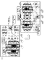
- FIG. 6 shows an example of a performer base potential map at four timings (t1 to t4).
- the map (t1) in the upper left of FIG. 6 is an example of the "performer base potential map" at time t1.
- the potential map is a map generated before the actual start of the live performance, and the position of the performer is the expected position of the performer estimated according to the live program such as the live progress chart.
- the action schedule data indicating the position of the performer from the start to the end of the live (performance) is stored in A. It is generated and recorded in advance as performer action schedule data 111 .
- Performer Base Potential Map is a map in which different colors are assigned for each area according to the area (driving prohibited area, cautionary driving area, permitted driving area) determined according to the distance from the performer's position as shown below. is.
- a close-range position of the performer position is set to red as a travel-prohibited area.
- the mid-distance position of the performer position is set to yellow as a driving caution area.
- the long-distance position of the performer's position is set to blue as the travel-permissible region.
- the map (t2) in the upper right of FIG. 6 is an example of the "performer's base potential map" at time t2 after a certain period of time has elapsed from time t1.
- the two actors are moving to different positions than at time t1.
- the setting of these three areas ie, the travel prohibited area (red), the travel caution area (yellow), and the travel permitted area (blue), also changes.
- the map (t3) in the lower left of FIG. 6 is an example of the "performer's base potential map" at time t3 after a certain period of time has elapsed from time t2.
- the two actors are moving to positions different from those at times t1 and t2.
- the setting of these three areas ie, the travel prohibited area (red), the travel caution area (yellow), and the travel permitted area (blue), also changes.
- the map (t4) in the lower right of FIG. 6 is an example of the "performer's base potential map" at time t4 after a certain period of time has elapsed from time t3.
- the two performers are moving to positions different from those at times t1-t3.
- the setting of these three areas ie, the travel prohibited area (red), the travel caution area (yellow), and the travel permitted area (blue), also changes.
- the "Performer Base Potential Map” dynamically changes each area (driving prohibited area, cautionary driving area, permitted driving area) according to the position of the performer from the start time to the end time of the live (performance). This is a time series map.
- the action schedule data indicating the position of the performer from the start to the end of the live (performance) is stored in A. It is generated and recorded in advance as performer action schedule data 111 .
- the individual potential map generation unit 120 stores the A.
- Generate a ⁇ performer-based potential map''.
- the "Lighting Base Potential Map” is used for each area (no-driving area, caution-not-driving area, This is a time-series map in which the allowable area) is dynamically changed, and is a time-series map in which the following three areas (b1 to b3) are set.
- No-travel area (red) Area conspicuous due to lighting conditions (bright area or lighting area with a different color than the image capturing robot) b3.
- Permissible travel area (blue) Inconspicuous area due to lighting conditions (dark area or lighting area with the same color as the image capturing robot) b2.
- Driving caution area (yellow) intermediate area between b1 and b3
- FIG. 7 shows an example of illumination base potential maps at four timings (t1 to t4).
- the map (t1) in the upper left of FIG. 7 is an example of the "illumination base potential map" at time t1.
- This map (t1) is an example of a map in a state where the illumination is dark overall at the start of a live performance, for example.
- the map (t2) in the upper right of FIG. 7 is an example of the "illumination base potential map" at time t2 after a certain period of time has elapsed from time t1.
- the illumination state (illumination position, brightness, color, etc.) is set to a state different from that at time t1.
- the setting of these three areas ie, no-travel area (red), caution-driving area (yellow), and permissible-travel area (blue), also changes.
- Lighting Base Potential Map is based on areas (no-driving areas, caution-driving areas, permissible driving areas) determined according to lighting conditions (lighting position, brightness, color, etc.) as shown below.
- a map with different colors That is, areas that are conspicuous due to lighting conditions (bright areas or illumination areas with a color different from that of the image capturing robot) are set to red as travel-prohibited areas. Areas that are inconspicuous due to the lighting conditions (dark areas and illumination areas of the same color as the image capturing robot) are set to blue as travel-permissible areas. An intermediate area between the travel-prohibited area and the travel-allowed area is set in yellow as a travel caution area.
- the map (t3) in the lower left of FIG. 7 is an example of the "illumination base potential map" at time t3 after a certain period of time has elapsed from time t2.
- the lighting conditions (illumination position, brightness, color, etc.) are different from those at times t1 and t2.
- the setting of these three areas ie, no-travel area (red), caution-driving area (yellow), and permissible-travel area (blue), also changes.
- the map (t4) in the lower right of FIG. 7 is an example of the "illumination base potential map" at time t4 after a certain period of time has elapsed from time t3.
- the lighting conditions (illumination position, brightness, color, etc.) are set to a state different from that at times t1 to t3.
- the setting of these three areas ie, no-travel area (red), caution-driving area (yellow), and permissible-travel area (blue), also changes.
- the "Lighting Base Potential Map” can be used for each area (no driving area, caution driving area, etc.) according to changes in the lighting conditions (lighting position, brightness, color, etc.) from the start time to the end time of the live (performance). It is a time-series map in which the area, driving allowable area) is dynamically changed.
- transition schedule data of lighting conditions (lighting position, brightness, color, etc.) from the start to the end of a live performance (performance) are stored in B. It is generated and recorded in advance as stage lighting control schedule data 112 .
- the individual potential map generation unit 120 stores the B.
- Generate map b “illumination base potential map”.
- Objects are objects placed on the stage, such as speakers, monitors, and decorative objects.
- FIG. 8 shows examples of object-based potential maps at four timings (t1 to t4).
- the map (t1) in the upper left of FIG. 8 is an example of the "object-based potential map" at time t1. Speakers, monitors, decorative objects, and the like are placed on the stage, and some of these are moved or replaced as the live progresses.
- the "object-based potential map” has different colors for each area according to the area (no-driving area, cautionary driving area, permitted driving area) determined according to the distance from the object placement position as shown below. is a map.
- the close distance position of the object arrangement position is set to red as a travel prohibited area.
- a middle-distance position of the object arrangement position is set to yellow as a driving caution area.
- the long-distance position of the object placement position is set to blue as the travel permissible region.
- the map (t2) on the upper right of FIG. 8 is an example of the "object-based potential map" at time t2 after a certain period of time has elapsed from time t1.
- the object on the stage has been moved or replaced to a different position than at time t1.
- the setting of these three areas ie, the travel prohibited area (red), the travel caution area (yellow), and the travel permitted area (blue), also changes.
- the map (t3) in the lower left of FIG. 8 is an example of the "object-based potential map" at time t3 after a certain period of time has elapsed from time t2.
- the object on the stage has been moved or replaced to a position different from that at times t1 and t2.
- the setting of these three areas ie, the travel prohibited area (red), the travel caution area (yellow), and the travel permitted area (blue), also changes.
- the map (t4) in the lower right of FIG. 8 is an example of the "object-based potential map" at time t4 after a certain period of time has elapsed from time t3.
- the object on the stage has moved or been replaced to a position different from that at times t1-t3.
- the setting of these three areas ie, the travel prohibited area (red), the travel caution area (yellow), and the travel permitted area (blue), also changes.
- the "object-based potential map” moves each area (no driving area, caution driving area, permitted driving area) according to the position of objects on the stage from the start time to the end time of the live (performance). It is a time-series map that changes dynamically.
- on-stage object placement schedule data indicating the placement positions of objects from the start to the end of a live (performance) is stored in the C.I. It is generated and recorded in advance as on-stage object placement schedule data 113 .
- the individual potential map generation unit 120 stores the C.I.
- the on-stage object placement schedule data 113 is acquired, the acquired data is referenced, and each area (no-driving area, caution-driving area, permissible-driving area) is dynamically changed from the start to the end of the live (performance).
- Generate a series map c “object-based potential map”.
- map a performer base potential map
- map b lighting base potential map
- map c object-based potential map
- the potential map synthesizing unit 130 generates a pre-generated potential map 150 by synthesizing the three individual potential maps generated by the individual potential map generating unit 120 .
- the pre-generated potential map 150 is also a time-series map in which each region (driving prohibited region, cautionary driving region, permitted driving region) is dynamically changed from the start to the end of the live (performance).
- FIG. 1 A specific example of the pre-generated potential map 150 generated by the potential map synthesizing unit 130 is shown in FIG.
- FIG. 9 shows an example of pre-generated potential maps 150 at four timings (t1 to t4) similar to the individual potential maps described with reference to FIGS. 6 to 8.
- FIG. 9 shows an example of pre-generated potential maps 150 at four timings (t1 to t4) similar to the individual potential maps described with reference to FIGS. 6 to 8.
- the pre-generated potential maps for the four timings (t1 to t4) shown in FIG. 9 are respectively generated by synthesizing the individual potential maps for the same four timings (t1 to t4) shown in FIGS. 6 to 8 for each timing. It is a map that
- the map (t1) in the upper left of FIG. 9 is the “pre-generated potential map” at time t1.
- This "pre-generated potential map” at time t1 is a performer base potential map at time t1 shown in FIG. 6 (t1); an illumination base potential map at time t1 shown in FIG. 7 (t1); Object-based potential map at time t1 shown in FIG. 8 (t1), This map is obtained by synthesizing these three individual potential maps at the same timing (t1).
- a specific synthesizing process sequence will be described later, but for example, the synthesizing process is performed by the following process.
- Such quantification is performed, the numerical values of each region of each individual potential map are added, and a pre-generated potential map as a composite map is generated based on the addition result.
- an area with an additional value of 10 or more is a driving prohibited area
- an area with an additional value of 5 or more and less than 10 is a driving caution area
- an area with an additional value of less than 5 is a driving permitted area.
- the "pre-generated potential map" shown in FIG. 9 (t1) is a performer base potential map at time t1 shown in FIG. 6 (t1); an illumination base potential map at time t1 shown in FIG. 7 (t1); Object-based potential map at time t1 shown in FIG. 8 (t1), A map generated by digitizing and adding each area (driving prohibition area, caution driving area, driving allowable area) of the individual potential map at the same timing (t1), and performing area division based on the above added value. be.
- Pre-generated potential map considers all of the performer's position, lighting conditions (lighting position, brightness, color), and object placement position, and determines the driving prohibited area, driving caution area, and driving permitted area. This is a map in which the following different colors are assigned for each area.
- the no-travel area is set in red.
- the driving caution area is set to yellow.
- the permissible travel area is set in blue.
- the map (t2) in the upper right of FIG. 9 is an example of a composite map at time t2 after a certain period of time has elapsed from time t1, that is, a "previously generated potential map.”
- the performer's position, lighting conditions (lighting position, brightness, color), and object placement positions are set differently from those at time t1.
- the "pre-generated potential map" at time t2 is a performer base potential map at time t2 shown in FIG. 6 (t2); an illumination base potential map at time t2 shown in FIG. 7 (t2); Object-based potential map at time t2 shown in FIG. 8 (t2), This map is generated by quantifying and adding the respective regions (driving prohibited region, cautionary driving region, and permitted driving region) of these three individual potential maps at the same timing (t2), and performing region division based on the added value.
- the map (t3) in the lower left of FIG. 9 is an example of a synthesized map at time t3 after a certain period of time has elapsed from time t2, that is, a "previously generated potential map.”
- the performer's position, lighting conditions (lighting position, brightness, color), and object placement positions are set differently from those at times t1 and t2.
- the "pre-generated potential map" at time t3 is a performer base potential map at time t3 shown in FIG. 6 (t3); an illumination base potential map at time t3 shown in FIG. 7 (t3); Object-based potential map at time t3 shown in FIG. 8 (t3), This map is generated by quantifying and adding the respective regions (driving prohibited region, cautionary driving region, and permitted driving region) of these three individual potential maps at the same timing (t3), and performing region division based on the added value.
- the map (t4) in the lower right of FIG. 9 is an example of a composite map at time t4 after a certain period of time has elapsed from time t3, that is, a "previously generated potential map.”
- the performer's position, lighting conditions (lighting position, brightness, color), and object placement positions are set differently from those at times t1 to t3.
- the "pre-generated potential map" at time t4 is a performer base potential map at time t4 shown in FIG. 6 (t4); an illumination base potential map at time t4 shown in FIG. 7 (t4); Object-based potential map at time t4 shown in FIG. 8 (t4), This map is generated by quantifying and adding the respective regions (driving prohibited region, cautionary driving region, and permitted driving region) of these three individual potential maps at the same timing (t4), and performing region division based on the added value.
- the potential map synthesizing unit 130 digitizes and adds each region (driving prohibited region, cautionary driving region, permissible driving region) of a plurality of individual potential maps at the same timing, performs region segmentation based on the added value, and generates in advance. Generate a potential map 150 .
- the pre-generated potential map 150 generated by the potential map synthesizing section 130 is provided to the driving route generating section 160, and the driving route generating section 160 generates a map from the start to the end of the live (performance) based on the pre-generated potential map 150.
- a travel route of the image capturing robot 50 is determined.
- the travel route generating unit 160 receives the pre-generated potential map 150 generated by the potential map synthesizing unit 130, and the image capturing robot 50 performs live (performance) from start to finish.
- Running route information 165 is generated in which a route for selecting and running an area that is not conspicuous due to illumination is selected without colliding with objects on the stage or on the stage.
- the travel route generator 160 for example, creates a travel route that travels only in the permissible travel area in the pre-generated potential map 150.
- the generated travel route is provided to the travel control unit 170 that controls travel of the image capturing robot 50 , and the travel control unit 170 causes the image capturing robot 50 to travel according to the generated travel route information 165 .
- the traveling control unit 170 may be configured as an information processing device within the image capturing robot 50 or may be configured as an information processing device capable of communicating with a robot outside the image capturing robot 50 .
- the image capturing robot 50 can be placed on the performer or on the stage from the start to the end of the live (performance). It is possible to select and run an area that is not conspicuous due to illumination without colliding with objects.
- FIG. 11 shows an example of the travel route of the image capturing robot 50 from time (t3) to (t4).
- the travel route of the image capturing robot 50 from time (t3) to (t4) shown in FIG. is.
- the performer and objects on the stage will be affected from the start to the end of the live (performance). It is possible to select and run an area that is not conspicuous by lighting without colliding.
- FIG. 12 Sequence for generating map a "performer base potential map”
- Fig. 13 to Fig. 14 Sequence for generating map b "illumination base potential map”
- Fig. 15 Map c "object base potential map” ” generation sequence
- FIG. 16 is a processing sequence for generating a "previously generated potential map", which is a synthetic map, executed by the potential map synthesizing unit 130 of the information processing apparatus 100 shown in FIG.
- the processing according to the flow described below can be executed, for example, according to a program stored in the storage unit of the information processing device, under the control of a control unit having a program execution function such as a CPU. is executed in Details of the processing of the flow shown in FIG. 14 will be sequentially described below.
- step S11 executed by the individual potential map generation unit 120 described above with reference to FIG. Equivalent to detailed sequence.
- map a base potential of the performer, which is a time-series map in which each area (no-driving area, caution-not-driving area, permitted-driving area) is dynamically changed according to the position of the performer from the start to the end of the live performance. 4 is a detailed sequence of map generation processing;
- This is, for example, performer action schedule data generated based on a preset live program, that is, "A. performer action schedule data 111" stored in the storage unit 110 of the information processing apparatus 100 shown in FIG. Executed as a process to get from
- Step S102 the data processing unit of the information processing device 100 selects one performer P to be analyzed.
- step S103 the data processing unit of the information processing apparatus 100 acquires time-series behavior data of the analysis target performer P from the start to the end of the live performance.
- This process also includes, for example, performer action schedule data generated based on a preset live program, that is, “A. ” is executed as a process to obtain from
- Step S104 the data processing unit of the information processing apparatus 100 generates a potential map based on the time-series action data of the performer P to be analyzed from the start to the end of the live performance.
- the close distance position of the position of the performer P is set to red as a travel prohibition area.
- the medium-distance position of the position of the performer P is set to yellow as a driving caution area.
- the long-distance position of the position of the performer P is set in blue as the travel-permissible region.
- step S105 the data processing unit of the information processing device 100 determines the presence or absence of an analysis-unprocessed performer. That is, it is determined whether or not generation of all performer base potential maps for the number of performers na acquired in step S101 has been completed.
- step S105 If there is an unprocessed performer, the determination in step S105 is Yes. In this case, the processing of step S102 and subsequent steps is executed for the unprocessed performers. On the other hand, if there is no unprocessed performer, that is, if it is determined that generation of all performer base potential maps for the number of performers na obtained in step S101 has been completed, the determination in step S105 is No. In this case, the process proceeds to step S106.
- Step S106 When the generation of all actor-based potential maps is completed, the data processing unit of the information processing apparatus 100 executes the processing from step S106 onwards.
- step S107 the data processing unit of the information processing apparatus 100 adds the numerical values corresponding to the regions of the potential maps of all the performers 1 to na for each region to calculate the added value corresponding to the regions.
- Step S108 the data processing unit of the information processing apparatus 100 resets the area divisions based on the added values corresponding to the areas of the potential maps of all the performers 1 to na.
- step S109 the data processing unit of the information processing apparatus 100 outputs the potential map whose area segmentation has been reset in step S108 to the potential map synthesizing unit 130 as a "performer base potential map.”
- map a is a time-series map in which each area (driving prohibited area, cautionary driving area, permitted driving area) is dynamically changed according to the performer's position from the start to the end of the live (performance). A base potential map is generated.
- step S12 executed by the individual potential map generator 120 described above with reference to FIG. It corresponds to the detailed sequence of generation processing.
- a map b which is a series map, is a detailed sequence of processing for generating an illumination base potential map.
- This processing is performed, for example, by the lighting control schedule data generated based on a preset live program, that is, the “B. 112”.
- Step S122 the data processing unit of the information processing device 100 selects one illumination position segmented region Q to be analyzed.
- step S123 the data processing unit of the information processing apparatus 100 acquires time-series lighting brightness information from the start to the end of the live performance of one lighting position segmented region Q selected as an analysis target.
- step S124 the data processing unit of the information processing device 100 generates a potential map based on the time-series lighting brightness data from the start to the end of the live performance of one lighting position segmented region Q selected as an analysis target. .
- the following area setting and color setting are performed.
- the brightness of the illumination position segmented region Q is equal to or higher than the specified threshold value Thd1, it is set to red as a travel-prohibited region.
- the brightness of the lighting position segmented region Q is within the range of the prescribed threshold values Thd1 and Thd2, it is set to yellow as the driving caution region. If the brightness of the illumination position segmented region Q is equal to or less than the specified threshold value Thd2, it is set to blue as the travel-permissible region.
- an illumination brightness base potential map corresponding to one illumination position segmented area Q is generated.
- step S125 the data processing unit of the information processing apparatus 100 determines whether or not there is an unanalyzed illumination position segmented area. In other words, it is determined whether or not the generation of the lighting brightness base potential maps for all of the number of lighting position segmented regions nb obtained in step S121 has been completed.
- step S125 If there is an unprocessed illumination position segmented area, the determination in step S125 is Yes. In this case, the processing from step S122 onward is executed for the unprocessed illumination position segmented regions. On the other hand, if there is no unprocessed illumination position segmented region, that is, if it is determined that the illumination brightness base potential map generation for all the illumination position segmented regions nb acquired in step S121 has been completed, the determination in step S125 is No. In this case, the process proceeds to step S126.
- Step S126 When the generation of all lighting brightness base potential maps is completed, the data processing unit of the information processing device 100 executes the processing from step S126 onward.
- step S126 one illumination position segmented area Q to be analyzed is selected.
- step S127 the data processing unit of the information processing apparatus 100 acquires time-series lighting color information from the start to the end of the live performance of one lighting position segmented region Q selected as an analysis target.
- Step S128 the data processing unit of the information processing device 100 generates a potential map based on the time-series illumination light color data from the start to the end of the live performance of one illumination position segmented region Q selected as an analysis target. .
- the following area setting and color setting are performed.
- red is set as the travel prohibition area.
- the illumination light color of the illumination position segmented area Q is a color different from that of the image capturing robot, if it is not a similar color, it is set to yellow as a travel caution area.
- blue is set as the travel permitted area.
- an illumination color base potential map corresponding to one illumination position segmented area Q is generated.
- step S129 the data processing unit of the information processing device 100 determines whether or not there is an unanalyzed illumination position segmented area. That is, it is determined whether or not all the lighting color base potential maps for the lighting position segmented region number nb obtained in step S121 have been generated.
- step S129 If there is an unprocessed illumination position segmented area, the determination in step S129 is Yes. In this case, the processing from step S126 onward is executed for the unprocessed illumination position segmented regions. On the other hand, if there is no unprocessed illumination position segmented region, that is, if it is determined that the illumination color base potential map generation for all the illumination position segmented regions nb acquired in step S121 is completed, the determination in step S129 is No. becomes. In this case, the process proceeds to step S131.
- Step S131 When the generation of all lighting color base potential maps is completed, the data processing unit of the information processing device 100 executes the processing from step S131 onward.
- Step S132 the data processing unit of the information processing apparatus 100 adds the numerical values corresponding to the set areas of the illumination brightness base potential map and the illumination color base potential map for each area, Calculate the value.
- the map is time-series data, ie, run for all stage positions on the map at all times.
- Step S133 the data processing unit of the information processing apparatus 100 resets the area divisions based on the added values corresponding to the areas of the illumination brightness base potential map and the illumination color base potential map.
- Step S134 the data processing unit of the information processing apparatus 100 outputs the potential map whose area division has been reset in step S133 to the potential map synthesizing unit 130 as an "illumination base potential map.”
- map b illumination base potential map generation processing executed by the individual potential map generation unit 120 .
- each area no driving area, caution driving area, permitted driving area
- a map b illumination base potential map, which is a time-series map, is generated.
- processing according to the flowchart shown in FIG. 15 is the processing of step S13 executed by the individual potential map generation unit 120 described above with reference to FIG. Equivalent to detailed sequence.
- Objects are objects placed on the stage, such as speakers, monitors, and decorative objects.
- This is, for example, stage object placement schedule data generated based on a preset live program, that is, "C.
- Stage object placement schedule data stored in the storage unit 110 of the information processing apparatus 100 shown in FIG. It is executed as a process of acquiring from the schedule data 113.
- Step S152 the data processing unit of the information processing device 100 selects one object Ob to be analyzed.
- Step S153 the data processing unit of the information processing apparatus 100 acquires time-series arrangement data from the start to the end of the live performance of the object Ob to be analyzed.
- This process is also performed, for example, on-stage object placement schedule data generated based on a preset live program, that is, "C. on-stage object arrangement data" stored in the storage unit 110 of the information processing apparatus 100 shown in FIG. It is executed as a process of acquiring from the arrangement schedule data 113.
- Step S154 the data processing unit of the information processing device 100 generates a potential map based on the time-series arrangement data from the start to the end of the live performance of the object Ob to be analyzed.
- the short distance position of the arrangement position of the object Ob is set to red as a travel prohibited area.
- the middle distance position of the arrangement position of the object Ob is set to yellow as a driving caution area.
- the long-distance position of the arrangement position of the object Ob is set to blue as the travel-permissible region.
- step S155 the data processing unit of the information processing apparatus 100 determines whether or not there is an analysis-unprocessed object. That is, it is determined whether generation of all object-based potential maps for the number of objects nc acquired in step S151 has been completed.
- step S155 If there is an unprocessed object, the determination in step S155 is Yes. In this case, the processing of step S152 and subsequent steps is executed for the unprocessed object. On the other hand, if there are no unprocessed objects, that is, if it is determined that generation of all object-based potential maps for the number of objects nc acquired in step S151 has been completed, the determination in step S155 is No. In this case, the process proceeds to step S156.
- Step S156 When the generation of all object-based potential maps is completed, the data processing unit of the information processing device 100 executes the processes from step S156 onward.
- step S157 the data processing unit of the information processing apparatus 100 adds the numerical values corresponding to the regions of the potential maps of all the objects 1 to nc for each region to calculate the added value corresponding to the regions.
- Step S158 the data processing unit of the information processing apparatus 100 resets the area divisions based on the added values corresponding to the areas of the potential maps of all the objects 1 to nc.
- Step S159 the data processing unit of the information processing apparatus 100 outputs the potential map whose area division has been reset in step S158 to the potential map synthesizing unit 130 as an "object-based potential map.”
- map c object-based potential map generation processing executed by the individual potential map generation unit 120 .
- the map c which is a time-series map in which each area (driving prohibition area, caution driving area, driving permitted area) is dynamically changed according to the object arrangement position from the start to the end of the live (performance). An object-based potential map is generated.
- the flowchart shown in FIG. 16 is a sequence of generating a pre-generated potential map executed by the potential map synthesizing unit 130 .
- processing of each step of the flow shown in FIG. 16 will be described in order.
- step S174 the data processing unit of the information processing apparatus 100 generates the potential map with the area segmentation reset in step S173 as a synthesized map, that is, a "previously generated potential map.”
- the pre-generated potential map 150 generated by the potential map synthesizing section 130 is provided to the driving route generating section 160, and the driving route generating section 160 generates a map from the start to the end of the live (performance) based on the pre-generated potential map 150.
- a travel route of the image capturing robot 50 is determined.
- the travel route generating unit 160 receives the pre-generated potential map 150 generated by the potential map synthesizing unit 130, and the image capturing robot 50 performs live (performance).
- Running route information 165 is generated in which a route for selecting and running an area that is not conspicuous by illumination without colliding with performers or objects on the stage from the start to the end of is set. For example, a travel route that travels only in the permissible travel area in the pregenerated potential map 150 is generated.
- the generated travel route is provided to the travel control unit 170 that controls travel of the image capturing robot 50 , and the travel control unit 170 causes the image capturing robot 50 to travel according to the generated travel route information 165 .
- the image capturing robot 50 can be placed on the performer and on the stage from the start to the end of the live (performance). It is possible to select and run an area that is not conspicuous due to illumination without colliding with objects.
- the travel route of the image capturing robot 50 generated using the pre-generated potential map 150 can be displayed as a simulation image on the display unit of the information processing device 100, for example.
- the data processing unit of the information processing device 100 displays the planned travel route of the image capturing robot 50 from the start to the end of the live performance based on the travel route information 165 generated using the generated pre-generated potential map 150. Generate simulation data for A specific display example of this simulation data is shown in FIG.
- FIG. 17 shows an example of display data indicating the running positions of the image capturing robot 50 at time t3 and time t4, as a display example of simulation data.
- a user such as a robot control operator can confirm the travel route generated using the generated pre-generated potential map 150 .
- map a performer base potential map
- map b lighting base potential map
- map c object-based potential map
- the generated pre-generated potential map is used to determine the traveling route of the image capturing robot 50. It was a configuration that determined the For example, it is configured to perform processing for selecting a travel-permissible region in the pre-generated potential map and determining a travel route for the image capturing robot 50 .
- a fourth individual potential map is created in consideration of the line of sight of the spectators and the line of sight of the television camera on the side of the spectator seats. This is an embodiment for generating a pre-generated potential map that also considers the 4 individual potential maps.
- the image capturing robot 50 shown in FIG. 18 is a mobile device on which a camera is mounted, that is, a traveling robot, similar to the image capturing robot 50 shown in FIG. Shoot from an angle.
- the image capturing robot 50 may enter between the performer 20 and the audience 30 or TV camera 31 on the audience seat side.
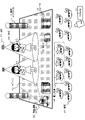
- FIG. 19 shows an example of a live venue where the processing of the second embodiment is performed. As shown in FIG. 19, on a stage 10 where a live performance is actually performed, a speaker 12, a monitor 13, and various decoration objects 14 are placed.
- the performer 20 moves around the stage as the live performance progresses, and the position, brightness, and color of the lighting 11 change according to this movement.
- the decoration object 14 is also changed in various ways.
- FIG. 19 there are many spectators 30 on the side of the audience seats, and a TV camera 31 is also arranged to photograph the live performance of the performer 20 .
- a potential map is generated in consideration of the viewpoint positions of some of the spectators 30, that is, the priority spectators 35 shown in the figure and the viewpoint positions of the TV camera 31.
- a potential map is generated in consideration of the viewpoint positions of all spectators, a potential map is generated in which the entire stage is set as a travel-prohibited area, and there is almost no travel-permissible area for the image capturing robot 50. Processing considering the viewpoint position of the priority spectator 35 is performed.
- the priority spectator 35 shown in the drawing is, for example, a seat reserved as a seat for related persons, and a reserved seat already reserved as a reserved seat for an important audience.
- a potential map is generated in consideration of the viewpoint position of the priority spectator 35 and the viewpoint position of the TV camera 31 . Details of the second embodiment will be described with reference to FIG. 20 and subsequent drawings.
- FIG. 20 is a diagram illustrating a configuration example of the information processing apparatus 100b according to the second embodiment of the present disclosure.
- the information processing device 100b may be configured inside the mobile device running on the stage shown in FIGS. or an independent device from the image capturing robot 50.
- FIG. 20 is a diagram illustrating a configuration example of the information processing apparatus 100b according to the second embodiment of the present disclosure.
- the information processing device 100b may be configured inside the mobile device running on the stage shown in FIGS. or an independent device from the image capturing robot 50.
- the information processing device 100 b has a storage section 110 , an individual potential map generation section 120 , a potential map synthesis section 130 and a travel route generation section 160 .
- These basic configurations are the same as those of the information processing apparatus 100 previously described with reference to FIG.
- the information processing device 100b shown in FIG. 20 may also be configured inside the moving device traveling on the stage shown in FIGS. 5, it may be a device independent of the image capturing robot 50, such as a device (server) capable of communicating with the image capturing robot 50.
- a device server
- the storage unit 110 stores the following four data.
- A. performer action schedule data 111 B. stage lighting control schedule data 112
- C. On-stage object placement schedule data 113 D. Priority spectators, TV camera viewpoint position data 114,
- these four scheduled data are data that are prepared in advance and stored in the storage unit 110 before the start of the live performance. That is, it is schedule data prepared in advance according to a program such as a live progress table prepared before the start of the live performance.
- Data A to C are the same data as the data described with reference to FIG. 4 in the first embodiment. i.e. A.
- the performer action schedule data 111 is time-series position data of performers moving around on stage during a live performance. That is, it is time-series position data of the performer from the start to the end of the live (performance).
- the stage lighting control schedule data 112 is time-series data of lighting control information including lighting setting information such as the lighting position, brightness, and color of the lighting from the start to the end of the live (performance).
- the on-stage object placement schedule data 113 is time-series data of on-stage object placement position information including the placement positions of on-stage objects from the start to the end of a live performance (performance).
- the on-stage objects include speakers, monitors, decorative objects, and the like placed on the stage.
- Example 2 in addition to these data A to C, D. Priority spectators, TV camera viewpoint position data 114, This data D is stored in the storage unit 110 .
- the priority spectator/TV camera viewpoint position data 114 is the viewpoint position data of the priority spectator on the spectator seat side from the start to the end of the live (performance) and the viewpoint position data of the TV camera.
- the priority spectator and TV camera viewpoint position data 114 are chronological data that dynamically change with the passage of time. However, when the viewpoint position of the priority audience and the viewpoint position of the TV camera are at the same position from the start to the end of the live (performance), D.
- the priority spectator and TV camera viewpoint position data 114 can be one fixed data.
- the data A to D stored in the storage unit 110 are used in the individual potential map generation unit 120.
- FIG. The individual potential map generation unit 120 uses the four types of data A, B, C, and D individually to generate the following four types of individual potential maps.
- map a performer base potential map
- map b lighting base potential map
- map c object-based potential map
- map d priority spectator, TV camera viewpoint position base potential map,
- Maps a to c are the individual potential maps previously described in the first embodiment.
- Map b lighting base potential map shows each area (no driving area, caution driving area, permitted driving area) according to the lighting conditions (lighting position, brightness, color, etc.) from the start to the end of the live (performance). This is a dynamically changed time series map.
- Map c Object-based potential map is a time series map that dynamically changes each area (no driving area, caution driving area, permitted driving area) according to the object placement position from the start to the end of the live (performance) is.
- Map d priority spectator, TV camera viewpoint position base
- the potential map is a map in which each area (driving prohibited area, caution caution area, permitted driving area) is set according to the priority spectator on the spectator seat side and TV camera viewpoint position. be.
- this map changes the setting area (running prohibited area) with the passage of time.
- driving caution area, driving permissible area) becomes time-series data that dynamically changes.
- the viewpoint position of the priority spectators and the viewpoint position of the TV camera are at the same position from the start to the end of the live performance (performance), the set areas (no driving area, caution driving area, permitted driving area) will move. It becomes one map that does not change dynamically.
- the individual potential map generator 120 generates the following four maps in steps S11 to S14 shown in FIG. i.e.
- step S14 the individual potential map generation unit 120 generates a moving image from a short-distance position to a long-distance position on a straight line connecting the priority audience viewpoint position and the TV camera viewpoint position to the stage center position.
- Generate a map d priority spectator, TV camera viewpoint position base potential map divided into prohibited area (red), driving caution area (yellow), and driving permitted area (blue).
- the individual potential map generator 120 generates the following four individual potential maps.
- map a performer base potential map
- map b lighting base potential map
- map c object-based potential map
- map d priority spectator, TV camera viewpoint position base potential map
- the potential map synthesizing unit 130 performs synthesizing processing of the four individual potential maps generated by the individual potential map generating unit 120 to generate pre-generated potential maps b, 150b.
- the pre-generated potential maps b, 150b are also time-series maps in which each region (driving prohibited region, cautionary driving region, permitted driving region) is dynamically changed from the start to the end of the live (performance).
- the “pre-generated potential map b” generated in the second embodiment takes into consideration all of the performer position, lighting conditions (lighting position, brightness, color), object placement position, and the priority audience viewpoint and TV camera viewpoint.
- This is a map in which a driving prohibited area, a driving caution area, and a driving permitted area are determined by using the map, and the following different colors are assigned for each determined area.
- the no-travel area is set in red.
- the driving caution area is set to yellow.
- the permissible travel area is set in blue.
- the pre-generated potential map b, 150b generated by the potential map synthesizing unit 130 is provided to the driving route generating unit 160, and the driving route generating unit 160 starts the live (performance) based on the pre-generated potential map b, 150b.
- a running route of the image capturing robot 50 from 1 to 1 is determined.
- the running route generating unit 160 receives the pre-generated potential maps b and 150b generated by the potential map synthesizing unit 130, and the image capturing robot 50 collides with performers and objects on the stage from the start to the end of the live (performance). Also, the driving route information 165 is generated in which a route for driving is set by selecting an area that is not conspicuous due to lighting and an area that does not interfere with the line of sight of the priority spectators 35 or the photographing of the TV camera 31. .
- the travel route generation unit 160 for example, generates a travel route that travels only in the permissible travel area in the pre-generated potential map b, 150b.
- the generated travel route is provided to the travel control unit 170 that controls travel of the image capturing robot 50 , and the travel control unit 170 causes the image capturing robot 50 to travel according to the generated travel route information 165 .
- the image capturing robot 50 can be used as a live (performance) map. From the start to the end of , select and run an area that does not collide with performers or objects on the stage, does not stand out due to lighting, and does not interfere with the line of sight of the priority audience 35 or the shooting of the TV camera 31. becomes possible.
- Step S202 the data processing unit of the information processing apparatus 100 selects one priority spectator viewpoint or TV camera viewpoint S to be analyzed.
- step S203 the data processing unit of the information processing apparatus 100 acquires time-series position data from the start of the live performance to the end of the priority audience viewpoint or the TV camera viewpoint S to be analyzed.
- This processing is also performed, for example, based on the priority spectator viewpoint and TV camera viewpoint position data generated based on a preset live program, that is, the "D. Priority audience, TV camera viewpoint position data 114”.
- the time-series position data from the live start to the end of the priority audience viewpoint or the TV camera viewpoint S may be data that dynamically changes with the passage of time, or one fixed data that does not change. Sometimes.
- Step S204 the data processing unit of the information processing apparatus 100 generates a potential map based on the position data from the live start to the end of the priority audience viewpoint or TV camera viewpoint S selected as the analysis target.
- each area (travel prohibition area, travel caution area, travel permission area) is set according to the map as described above with reference to FIG. Generate a map.
- a priority spectator/TV camera viewpoint base potential map corresponding to one priority spectator viewpoint or TV camera viewpoint S to be analyzed is generated.
- step S205 the data processing unit of the information processing apparatus 100 determines whether or not there is a priority spectator viewpoint or a TV camera viewpoint that has not been analyzed yet. That is, it is determined whether or not generation of the priority spectator/TV camera viewpoint base potential map for all the priority spectators and the TV camera viewpoint number nd acquired in step S201 is completed.
- step S205 If there is an unprocessed priority audience viewpoint or TV camera viewpoint, the determination in step S205 is Yes. In this case, the processing from step S202 onward is executed for the unprocessed priority spectator viewpoint or TV camera viewpoint. On the other hand, if there are no unprocessed priority spectator viewpoints or TV camera viewpoints, that is, generation of the priority spectator and TV camera viewpoint base potential map for all of the priority spectator and TV camera viewpoints nd acquired in step S201 is completed. If so, the determination in step S205 is No. In this case, the process proceeds to step S206.
- Step S206 When the generation of the base potential maps for all priority spectators and TV camera viewpoints is completed, the data processing unit of the information processing apparatus 100 executes the processing from step S206 onwards.
- step S207 the data processing unit of the information processing apparatus 100 adds the numerical values corresponding to the regions of the potential maps of all the priority spectator viewpoints or the TV camera viewpoints 1 to nd for each region, Calculate the added value.
- the total number of priority spectator and TV camera viewpoints is 3, and individual priority spectator and TV camera viewpoint base potential maps (m1 to m3) corresponding to the three priority spectator viewpoints or TV camera viewpoints are generated.
- Such addition processing is performed for all maps. Note that when the map is time-series data, all stage positions of the map at all times are executed.
- step S208 the data processing unit of the information processing apparatus 100 resets the area divisions based on the added values corresponding to the areas of the potential maps of all the priority spectator viewpoints or the TV camera viewpoints 1 to nd.
- step S209 the data processing unit of the information processing apparatus 100 outputs the potential map whose area segmentation has been reset in step S208 to the potential map synthesizing unit 130 as a "priority spectator, TV camera viewpoint base potential map".
- the flowchart shown in FIG. 23 is the sequence of generating the pre-generated potential map b executed by the potential map synthesizing unit 130 .
- processing of each step of the flow shown in FIG. 23 will be described in order.
- Such addition processing is performed for all maps.
- the map is time-series data, ie, run for all stage positions on the map at all times.
- step S224 the data processing unit of the information processing apparatus 100 generates the potential map with the area segmentation reset in step S223 as a synthesized map, ie, "previously generated potential map b".
- the pre-generated potential maps b and 150b generated by the potential map synthesizing section 130 are provided to the driving route generating section 160, and the driving route generating section 160 performs live (performance) from the start to the end based on the pre-generated potential map 150. Determine the travel route of the image capturing robot 50 up to .
- the travel route generating unit 160 receives the pre-generated potential maps b and 150b generated by the potential map synthesizing unit 130, and the image capturing robot 50 performs live ( (Performance) from start to finish without colliding with performers or objects on stage, select areas that will not be conspicuous due to lighting, and will not obstruct the view of the priority audience or TV cameras.
- the travel route information 165 that sets the route to be taken is generated. For example, a travel route that travels only in the permissible travel area in the pregenerated potential map 150 is generated.
- the generated travel route is provided to the travel control unit 170 that controls travel of the image capturing robot 50 , and the travel control unit 170 causes the image capturing robot 50 to travel according to the generated travel route information 165 .
- the image capturing robot 50 can be placed on the performer or on the stage from the start to the end of the live (performance). It is possible to select and run an area that does not collide with an object, is not conspicuous due to illumination, and does not obstruct the view of priority spectators or TV cameras.
- Example 3 Regarding an example of generating a real-time data reflection potential map using information during live performance
- Example 3 an example of generating a real-time data reflection potential map using information during live performance will be described.
- data that can be acquired before a live performance on the stage is started that is, data stored in the storage unit 110 of the information processing apparatus 100 shown in FIGS.
- a potential map was generated using the following data.
- Each of the above data A to D used in the first and second embodiments is generated on the premise that the performer acts according to the live program, lighting control is performed, and objects are arranged. data. However, when a live performance actually starts, the performer's movement, lighting control, and the like may be performed differently from the original live program.
- Embodiment 3 described below is intended to prevent such a situation, and is an embodiment in which a potential map is generated by acquiring real-time data during an actual live performance, i.e., when performers are performing. be.
- FIG. 24 shows a configuration example of the information processing apparatus 200 of the third embodiment.
- the information processing device 200 includes a real-time stage information acquisition unit 201, a real-time spectator seat information acquisition unit 202, a real-time net information acquisition unit 203, a real-time stage information analysis unit 204, a storage unit 205, and a pre-generated potential map correction unit. It has a unit 206 , a real-time attention area analysis unit 207 , and a real-time data reflection potential map generation unit 208 .
- the information processing apparatus 200 shown in FIG. 24 may be configured, for example, inside the moving apparatus running on the stage shown in FIGS.
- a device independent of the image capturing robot 50 such as a device that can communicate with the image capturing robot 50, may be used.
- FIG. 25 shows a configuration example of an information processing system in which the information processing apparatus having the configuration shown in FIG. 24 is independent of the image capturing robot 50 .
- an information processing device (server) 200 a live venue information acquisition device 60, an image capturing robot 50 in the live venue, and an SNS server 290 are connected via a communication network.
- Build system 280 a communication network.
- the information processing apparatus (server) 100 has the configuration shown in FIG.
- the live venue information acquisition device 60 is composed of a camera that captures images of the live venue, a microphone that acquires audio information of the live venue, an illuminance meter that detects lighting conditions, a color analysis device, etc., and acquires information such as the acquired image. , to the information processing apparatus (server) 200 via the communication network.
- the information processing device (server) 200 analyzes information received from the live venue information acquisition device 60 and information acquired from the SNS server 290, and determines the travel route of the image capturing robot 50 in the live venue. A map (potential map) generation process, a travel route determination process using the map, and a travel control information generation process for the image capturing robot 50 according to the determined travel route are performed.
- the SNS server 290 is a server that collects comment information such as tweets of users browsing the live on the Internet.
- the information processing device (server) 200 analyzes the information acquired from the SNS server 290 and analyzes the attention area of the user who is watching the live performance via the net.
- the information processing device (server) 200 further transmits the generated travel control information to the image capturing robot 50 via the communication network.
- the image capturing robot 50 runs on the stage according to the running control information received from the information processing device (server) 100 . For example, it is possible to perform processing using such an information processing system.
- the real-time stage information acquisition unit 201 is configured by, for example, a camera, an illuminance meter, and the like, and acquires in real time information about an actual live performance, that is, a stage where a performer is performing.
- the real-time stage information acquisition unit 201 acquires the following information as real-time data, as shown in the drawing. performer position 211, lighting conditions 212; on-stage object position 213; image capturing robot position 214;
- the illumination state includes information on the position of the illuminated stage, the brightness of the illumination, and the color of the illumination.
- the real-time stage information acquisition unit 201 continuously acquires the performer position 211, the lighting state 212, the on-stage object position 213, the image capturing robot position 214, and each of these information as real-time data during the live performance period. is output to the real-time stage information analysis unit 204 .
- the real-time stage information analysis unit 204 acquires the performer position 211, the lighting state 212, the on-stage object position 213, and the image capturing robot position 214 input from the real-time stage information acquisition unit 201, and information stored in the storage unit 205 in advance. Compare schedule data 231 based on the live program currently in use and the pre-generated potential map 150 generated according to Example 1 or Example 2 above.
- the schedule data 231 based on the live program stored in the storage unit 205 is the same data as the following information described above with reference to FIGS. 4 and 20.
- the real-time stage information analysis unit 204 acquires the performer position 211, the lighting state 212, the on-stage object position 213, and the image capturing robot position 214 input from the real-time stage information acquisition unit 201, and information stored in the storage unit 205 in advance.
- the schedule data 231 based on the live program that is currently running is compared to confirm whether or not there is a difference.
- the image capturing robot 50 runs along the running route set using the pre-generated potential map 150 generated according to the first or second embodiment, it does not collide with the performer or the object. , and can be driven without being conspicuous by lighting.
- the image capturing robot 50 when the image capturing robot 50 is run along the running route set using the pre-generated potential map 150 generated according to the first or second embodiment, it will come into contact with the performer or the object. There is a possibility that the driving may be conspicuous due to lighting.
- the real-time stage information analysis unit 204 acquires the performer position 211, the lighting state 212, the on-stage object position 213, and the image capturing robot position 214 input from the real-time stage information acquisition unit 201, and information stored in the storage unit 205 in advance. If a difference is detected in the schedule data 231 based on the live program that is currently running, furthermore, whether there is any problem in driving the driving route according to the pre-generated potential map 150 generated according to the first or second embodiment. determine whether
- the pre-potential map correction unit 206 When a correction request for the pre-generated potential map is input from the real-time stage information analysis unit 204, the pre-potential map correction unit 206 reduces the possibility of contact with performers and objects and the possibility of conspicuous running due to lighting. , modify the pre-generated potential map 150 .
- a pre-potential map correction unit 206 corrects the pre-generated potential map 150 to generate a real-time stage information reflecting potential map.
- the real-time stage information reflection potential map reflects the real-time performer position 211, the lighting state 212, the on-stage object position 213, and the image capturing robot position 214 acquired by the real-time stage information acquisition unit 201, and each area (running prohibited area, running It is a map in which a caution area and a driving allowable area) are set.
- FIG. 26 shows the following two potential maps.
- Pre-generated potential map (2) Real-time stage information reflection potential map
- the pre-generated potential map is the pre-generated potential map 150 generated according to the first or second embodiment, and is a potential map stored in the storage unit 205 of the information processing apparatus 200 shown in FIG. be.
- the real-time stage information reflecting potential map is a map generated by the pre-potential map correction unit 206 correcting the pre-generated potential map 150 . That is, each area (no-run area, caution-run area, permitted-run area) reflects the real-time performer position 211, lighting state 212, on-stage object position 213, and image capturing robot position 214 acquired by the real-time stage information acquisition unit 201. ) is reconfigured.
- a pre-potential map correction unit 206 corrects the pre-generated potential map using real-time stage information to generate a real-time stage information-reflecting potential map.
- the real-time stage information reflecting potential map generated by the pre-potential map correction unit 206 is a map generated by reflecting the performer's position, lighting state, and object position in real time, and is a map in which the following area setting is performed, for example.
- Allowable travel area (blue) area far from real-time performer position and object position, and determined to be the least conspicuous based on real-time lighting conditions
- No-running area (red) area close to real-time performer position and object position, and determined to be conspicuous based on real-time lighting conditions
- Caution driving area (yellow) Intermediate area between the allowable driving area (blue) and the prohibited driving area (red),
- the real-time stage information reflecting potential map generated by the pre-potential map correcting unit 206 is output to the real-time data reflecting potential map generating unit 208 .
- the real-time audience seat information acquisition unit 202 is specifically composed of, for example, a camera, and acquires in real time the information of the audience seats in front of the stage where the performers are performing.
- the real-time spectator seat information acquisition unit 202 acquires the following information as real-time data, as shown in the figure. Audience line of sight direction 215, Audience seat side TV camera shooting direction 216,
- the audience viewpoint position 215 is the line-of-sight direction of the audience in front of the stage where the live performance is being performed.
- the audience seat side TV camera shooting direction 216 is the shooting direction of the TV camera in front of the stage where the live performance is being performed.
- the real-time net information acquisition unit 203 has a communication unit connected to a communication network such as the Internet, and acquires so-called SNS information 217 such as tweets of many live viewers on the net.
- the obtained SNS information 217 is input to the real-time attention area analysis unit 207 .
- the real-time attention area analysis unit 207 analyzes the audience line-of-sight direction 215 input from the real-time audience seat information acquisition unit 202, the audience seat side TV camera shooting direction 216, and the SNS information 217 input from the real-time net information acquisition unit 203. , which part of the stage the audience is looking at, which part of the stage is captured by the TV camera, and which part of the stage the live viewers on the Internet pay attention to.
- Real-time attention area analysis section 207 estimates the current attention area on the stage based on these analysis results, and outputs the estimated area to real-time data reflection potential map generation section 208 as real-time attention area information 221 shown in the figure. .
- the real-time data reflecting potential map generation unit 208 receives the following data. (1) “Real-time stage information reflecting potential map” generated by the prior potential map correction unit 206 (2) Real-time attention area information 221 generated by the real-time attention area analysis unit 207 The real-time data reflecting potential map generation unit 208 receives each of these data and generates a real-time data reflecting potential map 230 based on these input data.
- the real-time data reflecting potential map generation unit 208 sequentially executes the following processes 1 and 2.
- Process 1 Based on the real-time region-of-interest information 221 generated by the real-time region-of-interest analysis unit 207, a real-time region-of-interest-reflecting potential map that reflects the real-time region of interest is generated.
- a "real-time stage information reflection potential map" in which each area (travel prohibited area, caution caution area, allowable travel area) is set by reflecting the performer position 211, the lighting state 212, the on-stage object position 213, and the image capturing robot position 214. , the real-time attention area reflecting potential maps generated in process 1 are combined to generate a real-time data reflecting potential map 230 .
- FIG. 27 shows the following three potential maps.
- the real-time attention area reflected potential map is a map generated by the above (process 1) executed by the real-time data reflected potential map generation unit 208, and the real-time attention area information 221 generated by the real-time attention area analysis unit 207 is a potential map generated by reflecting the real-time region of interest based on.
- the real-time region-of-interest-reflecting potential map is a map generated by reflecting real-time audience, TV camera, and net information, and is a map in which the following region settings are made.
- Permissible driving area (blue) Non-attention area with the lowest attention based on real-time spectators, TV cameras, and net information
- No-driving areas (red) attention areas with the highest degree of attention based on real-time spectators, TV cameras, and internet information
- Caution driving area (yellow) Intermediate area between the allowable driving area (blue) and the prohibited driving area (red)
- the (4) real-time data reflection potential map 230 shown in FIG. 27 is shown in FIG. (2) Real-time stage information reflecting potential map (3) Real-time attention area reflecting potential map This map is generated by synthesizing two potential maps.
- the real-time data reflection potential map 230 generated by the real-time data reflection potential map generation unit 208 is a map generated by reflecting real-time information on the stage, real-time audience seat information, and real-time net information.
- the real-time data reflection potential map 230 generated by the real-time data reflection potential map generation unit 208 is a map generated by reflecting all real-time performer positions, lighting conditions, object positions, audience, TV cameras, and net information. area is set.
- Permissible travel area (blue) The most inconspicuous non-attention area based on real-time performer position, lighting condition, object position, audience, TV camera, net information
- No-running area (red) most conspicuous area of interest based on real-time performer position, lighting conditions, object position, audience, TV camera, and internet information
- Caution driving area (yellow) Intermediate area between the allowable driving area (blue) and the prohibited driving area (red)
- the real-time data reflecting potential map 230 generated by the real-time data reflecting potential map generating unit 208 is provided to the running route generating unit 240, and the running route generating unit 240 determines the running of the imaging robot 50 based on the real-time data reflecting potential map 230. determine the route.
- the travel route generation unit 240 inputs the real-time data reflection potential map 230, and the image capturing robot 50 does not collide with performers or objects on the stage, does not stand out due to lighting, and furthermore, travels to the audience and TV.
- Driving route information is generated in which a route for selecting and driving an area other than the attention area of the viewer on the camera and the Internet is set.
- the travel route generation unit 240 can set the travel route as described above, for example, by generating a travel route that travels only in the permissible travel area in the real-time data reflecting potential map 230 .
- the generated travel route is provided to the travel control unit that performs travel control of the image capturing robot 50, and the travel control unit causes the image capturing robot 50 to travel according to the generated travel route information.
- the image capturing robot 50 is caused to travel according to the travel route information generated using the real-time data reflection potential map 230 generated in the third embodiment, thereby performing a live performance of the image capturing robot 50.
- Step S301 First, in step S301, the information processing apparatus 200 acquires real-time stage information (performer position, lighting state, on-stage object position, image capturing robot position).
- This processing is processing executed by the real-time stage information acquisition unit 201 of the information processing apparatus 200 shown in FIG.
- the real-time stage information acquisition unit 201 is configured by, for example, a camera, an illuminance meter, etc., and acquires the performer's position, the performer's position, the performer's position, the information of the stage where the performer's performance is performed, as real-time stage information. Information on lighting conditions, object positions on the stage, and image capturing robot positions is acquired.
- Step S302 the information processing apparatus 200 modifies the previously generated potential map based on the real-time stage information acquired in step S301 to generate a potential map reflecting real-time stage information.
- step S302 is processing executed by the prior potential map correction unit 206 of the information processing apparatus 200 shown in FIG.
- step S301 the real-time stage information analysis unit 204 of the information processing apparatus 200 shown in FIG. position, illumination state, object position on the stage, image capturing robot position) and schedule data 231 based on the live program stored in advance in the storage unit 205, and the running route according to the pre-generated potential map 150 Analyze the problems of running.
- step S302 is a subsequent process, and when a request for correction of the pre-generated potential map is input from the real-time stage information analysis unit 204, the pre-potential map correction unit 206 receives a request for correction of the pre-generated potential map from the real-time stage information analysis unit 204.
- the pre-generated potential map 150 is modified to generate a real-time stage information reflecting potential map so as to reduce the possibility of conspicuous running due to .
- the real-time stage information reflecting potential map generated by the pre-potential map correction unit 206 is a map generated by reflecting the performer's position, lighting state, and object position in real time.
- Allowable travel area (blue) area far from real-time performer position and object position, and determined to be the least conspicuous based on real-time lighting conditions;
- No-running area (red) area close to real-time performer position and object position, and determined to be conspicuous based on real-time lighting conditions;
- Caution driving area (yellow) Intermediate area between the allowable driving area (blue) and the prohibited driving area (red),
- step S303 the information processing apparatus 200 acquires real-time spectator seat information and real-time net information.
- the real-time spectator seat information acquisition unit 202 acquires each of the following information as real-time data, as described above with reference to FIG. Audience line of sight direction 215, Audience seat side TV camera shooting direction 216, Also, the real-time net information acquisition unit 203 acquires so-called SNS information 217 such as tweets of impressions of many live viewers on the Internet, and inputs the acquired SNS information 217 to the real-time attention area analysis unit 207 .
- SNS information 217 such as tweets of impressions of many live viewers on the Internet
- Step S304 the information processing apparatus 200 analyzes the real-time attention area based on the real-time spectator seat information and the real-time net information acquired in step S303.
- This process is executed by the real-time attention area analysis unit 207 of the information processing apparatus 200 shown in FIG.
- the real-time attention area analysis unit 207 analyzes the audience line-of-sight direction 215 input from the real-time audience seat information acquisition unit 202, the audience seat side TV camera shooting direction 216, and the SNS information 217 input from the real-time net information acquisition unit 203. , which part of the stage the audience is looking at, which part of the stage the TV camera is shooting, and which part of the stage the live viewers on the Internet are paying attention to.
- Real-time attention area analysis section 207 estimates the current attention area on the stage based on these analysis results, and outputs the estimated area to real-time data reflection potential map generation section 208 as real-time attention area information 221 shown in FIG. do.
- Step S305 the information processing apparatus 200 generates a "real-time attention area reflecting potential map" reflecting the real-time attention area analyzed based on the real-time spectator seat information and the real-time net information.
- This process is executed by the real-time data reflecting potential map generation unit 208 of the information processing apparatus 200 shown in FIG.
- the real-time data reflection potential map generation unit 208 generates a "real-time attention area reflection potential map" that reflects real-time attention areas analyzed based on real-time spectator seat information and real-time net information.
- the real-time region-of-interest-reflecting potential map is a map generated by reflecting real-time audience, TV camera, and net information, and is a map in which the following region settings are made.
- Permissible driving area (blue) Non-attention area with the lowest attention based on real-time spectators, TV cameras, and net information
- No-driving areas (red) attention areas with the highest degree of attention based on real-time spectators, TV cameras, and internet information
- Caution driving area (yellow) Intermediate area between the allowable driving area (blue) and the prohibited driving area (red)
- step S306 the information processing apparatus 200 quantifies the "real-time stage information reflecting potential map", the “real-time attention area reflecting potential map”, and the set areas of each map.
- step S307 the information processing apparatus 200 adds the "real-time stage information reflecting potential map", the "real-time attention area reflecting potential map”, and the numerical values corresponding to the regions of each map to each region. Calculate the added value of
- This process is also a process executed by the real-time data reflection potential map generation unit 208 of the information processing apparatus 200 shown in FIG.
- step S308 the data processing unit of the information processing apparatus 200 resets the area division based on the added value corresponding to the area calculated in step S307.
- This process is also a process executed by the real-time data reflection potential map generation unit 208 of the information processing apparatus 200 shown in FIG.
- step S309 the data processing unit of the information processing apparatus 200 outputs the potential map with the area segmentation reset in step S308 as a "real-time data reflected potential map.”
- This process is also a process executed by the real-time data reflection potential map generation unit 208 of the information processing apparatus 200 shown in FIG.
- steps S301 and S302 of the flowchart shown in FIG. 28 the following processes are performed. Acquisition processing of real-time stage information (performer position, lighting state, on-stage object position, image capturing robot position) by the real-time stage information acquisition unit 201 of the information processing device 200 shown in FIG. Real-time stage information reflecting potential map generation processing is performed by correcting the potential map.
- real-time stage information performer position, lighting state, on-stage object position, image capturing robot position
- step S309 the real-time data reflection potential map 230 is generated. Based on this, the travel route of the image capturing robot 50 is determined and travel control is performed.
- the flowchart shown in FIG. 29 is a flow that can be executed by replacing the processing of steps S301 to S302 of the flow shown in FIG. Hereinafter, processing of each step of the flow shown in FIG. 29 will be described in order.
- Step S321 First, in step S321, the information processing apparatus 200 shown in FIG. 24 determines whether it is time to acquire real-time stage information.
- This process is executed by the real-time stage information acquisition unit 201 of the information processing apparatus 200 shown in FIG. 24 or by the control unit that controls the real-time stage information acquisition unit 201 .
- the acquisition timing of the real-time stage information is defined in advance such that the real-time stage information is acquired at regular intervals, such as every 10 seconds.
- step S321 it is determined whether or not it is time to acquire real-time stage information according to this rule. If it is determined that it is time to acquire real-time stage information, the process proceeds to step S322.
- Step S322 When it is determined in step S321 that it is time to acquire real-time stage information, the information processing apparatus 200 acquires real-time stage information (performer position, lighting state, on-stage object position, image capturing robot position) in step S322. .
- the real-time stage information acquisition unit 201 is configured by, for example, a camera, an illuminance meter, etc., and acquires the performer's position, the performer's position, the performer's position, the information of the stage where the performer's performance is performed, as real-time stage information. Information on lighting conditions, object positions on the stage, and image capturing robot positions is acquired.
- Step S323 the information processing apparatus 200 determines whether or not it is time for the image capturing robot to finish running.
- Information about the travel end time of the image capturing robot is stored in advance in the storage unit 205 of the information processing apparatus 200 . For example, it is recorded in association with the scheduled travel route of the image capturing robot.
- the information processing apparatus 200 refers to this recorded information and determines whether or not the current time is the end time of the image capturing robot running.
- step S324 If the current time is the running end time of the image capturing robot, the process ends. On the other hand, if the current time is not the running end time of the image capturing robot, the process proceeds to step S324.
- Step S324 If it is determined in step S323 that it is not the travel end time of the image capturing robot, the information processing apparatus 200 determines in step S324 whether it is the travel route change permissible time of the image capturing robot.
- Information as to whether or not it is the travel route change permissible time for the image capturing robot is stored in advance in the storage unit 205 of the information processing apparatus 200 . For example, it is recorded in association with the scheduled travel route of the image capturing robot.
- the information processing apparatus 200 refers to this recorded information and determines whether or not the current time is the travel route change permissible time for the image capturing robot.
- step S325 If the current time is not the travel route change permissible time for the image capturing robot, the process returns to step S321 without proceeding to step S325, and repeats the processes of steps S321 to S324. Only when it is determined that the current time is within the allowable travel route change time for the image capturing robot, the process proceeds to step S325.
- Step S325) If it is determined in step S324 that the current time is within the allowable travel route change time for the image capturing robot, the process of step S325 is executed.
- step S325 the information processing apparatus 200 combines the real-time stage information acquired in step S321 (the position of the performer, the lighting state, the position of the object on the stage, the position of the image capturing robot) with the previously generated potential map. comparison processing.
- step S325 is a process executed by the real-time stage information analysis unit 204 of the information processing device 200 shown in FIG.
- Step S326 the information processing apparatus 200 converts the travel route of the image capturing robot based on the pre-generated potential map into the real-time stage information (performer position, lighting state, on-stage object position, image capturing robot position) acquired in step S321. It is determined whether or not the setting is to pass through the dangerous area estimated from the position).
- step S326 is also a process executed by the real-time stage information analysis unit 204 of the information processing apparatus 200 shown in FIG.
- a real-time stage information analysis unit 204 analyzes real-time stage information (performer position, lighting state, object position on stage, image capturing robot position) input from the real-time stage information acquisition unit 201 and a live program stored in the storage unit 205 in advance. and the risk of the travel route according to the pre-generated potential map 150.
- step S321 If it is determined that there is no danger, that is, if the image capturing robot 50 runs along the running route set using the pre-generated potential map 150, there is a possibility that the robot will come into contact with a performer or an object, and the running will be conspicuous due to lighting. If it is determined that there is no possibility of being caught, the process returns to step S321 without proceeding to step S327, and the processes from step S321 onward are repeated.
- step S327 when it is determined that there is a danger, that is, when the image capturing robot 50 is caused to travel along the travel route set using the pre-generated potential map 150, there is a possibility that the robot 50 may come into contact with the performer or an object, or the travel may be conspicuous due to lighting. is likely to be performed, the process proceeds to step S327.
- Step S327) If it is determined in step S326 that the travel route set using the pre-generated potential map 150 has a risk of colliding with the performer, the information processing device executes the processing of step S327.
- step S327 the information processing apparatus 200 modifies the pre-generated potential map 150 stored in the storage unit 205 to generate a real-time stage information reflecting potential map.
- step S327 is a process executed by the pre-generated potential map correction unit 206 of the information processing apparatus 200 shown in FIG.
- a pre-potential map correction unit 206 corrects the pre-generated potential map 150 so as to reduce the possibility of contact with performers and objects and the possibility of conspicuous running due to lighting, and generates a potential map reflecting real-time stage information. do.
- the real-time stage information reflecting potential map generated by the pre-potential map correction unit 206 is a map generated by reflecting the performer's position, lighting state, and object position in real time.
- Allowable travel area (blue) area far from real-time performer position and object position, and determined to be the least conspicuous based on real-time lighting conditions;
- No-running area (red) area close to real-time performer position and object position, and determined to be conspicuous based on real-time lighting conditions;
- Caution driving area (yellow) Intermediate area between the allowable driving area (blue) and the prohibited driving area (red),
- step S303 onward of the flow shown in FIG. 28 is executed. That is, the processes of steps S303 to S309 are executed, and finally in step S309, the real-time data reflection potential map 230 is generated. A travel route is determined and travel control is performed.
- FIG. 30 includes the information processing apparatus 100 described with reference to FIG. 4, the information processing apparatus 100b described with reference to FIG. 20, and the information processing apparatus 200 described with reference to FIG. It is an example of the hardware configuration of.
- the hardware configuration shown in FIG. 30 will be described.
- a CPU (Central Processing Unit) 301 functions as a data processing section that executes various processes according to programs stored in a ROM (Read Only Memory) 302 or a storage section 308 . For example, the process according to the sequence described in the above embodiment is executed.
- a RAM (Random Access Memory) 303 stores programs and data executed by the CPU 301 . These CPU 301 , ROM 302 and RAM 303 are interconnected by a bus 304 .
- the CPU 301 is connected to an input/output interface 305 via a bus 304.
- the input/output interface 305 includes an input unit 306 including various sensors, a camera, a switch, a keyboard, a mouse, a microphone, and the like, and an output unit 307 including a display, a speaker, and the like. is connected.
- a storage unit 308 connected to the input/output interface 305 consists of, for example, a hard disk, and stores programs executed by the CPU 301 and various data.
- a communication unit 309 functions as a transmission/reception unit for data communication via a network such as the Internet or a local area network, and communicates with an external device.
- a drive 310 connected to the input/output interface 305 drives a removable medium 311 such as a magnetic disk, an optical disk, a magneto-optical disk, or a semiconductor memory such as a memory card to record or read data.
- a removable medium 311 such as a magnetic disk, an optical disk, a magneto-optical disk, or a semiconductor memory such as a memory card to record or read data.
- the technique disclosed in this specification can take the following configurations. (1) having a data processing unit that generates a potential map that defines an allowable travel area of an image capturing robot that moves on a stage and captures images; The data processing unit Acquiring at least one of the action schedule data of the performer on the stage and the arrangement schedule data of the object on the stage, and determining the probability of collision with the performer or the object on the stage based on the acquired data. An information processing device that generates a potential map that defines a permissible travel area below a value.
- the data processing unit Acquiring time-series data of action schedule data of the performer on the stage or arrangement schedule data of the object on the stage, and based on the obtained data, the probability of collision with the performer or the object on the stage is equal to or less than a prescribed threshold.
- the information processing device which generates time-series data of a potential map that defines a permissible travel area of .
- the data processing unit Acquisition of scheduled data for brightness control of illumination on the stage, and based on the acquired data, an area other than an area where the brightness of the illumination illuminated on the stage is equal to or higher than a predetermined threshold value is defined as an allowable travel area.
- the information processing apparatus according to any one of (1) to (3), which generates a defined potential map.
- the data processing unit Color control schedule data for lighting on the stage is acquired, and based on the acquired data, a potential map is generated in which an area other than an area where the illumination on the stage has a predetermined color value is defined as an allowable travel area.
- the information processing apparatus according to any one of (1) to (4).
- the data processing unit a permissible travel area in which the probability of collision with performers or objects on the stage is below a specified threshold;
- the information processing apparatus according to any one of (1) to (5), which generates a potential map defining a travel-prohibited area, which is an area closer to the performer or object on the stage than the allowable travel area.
- the data processing unit The information processing apparatus according to (6), which generates a potential map defining a travel caution area at an intermediate position between the allowable travel area and the prohibited travel area.
- the data processing unit (a) a performer-based potential map that defines a permissible travel region in which the possibility of collision with the performer on the stage is equal to or less than a specified threshold value, based on the action schedule data of the performer on the stage; (b) an object-based potential map that defines a permissible travel region in which the possibility of collision with an object on the stage is equal to or less than a predetermined threshold value, based on the arrangement plan data of the object on the stage; (c) Based on the lighting control schedule data on the stage, a region other than the region where the lighting state value calculated based on the lighting irradiated on the stage is equal to or greater than a predetermined threshold value is defined as the travel-permissible region.
- the pre-generated potential map is Areas other than areas where the possibility of collision with performers and objects on the stage is below a specified threshold and where the lighting condition value calculated based on lighting is above a predetermined threshold is defined as an allowable travel area.
- the data processing unit In the process of synthesizing the three types of individual potential maps (a) to (c), For each of the permissible driving region, the cautionary driving region, and the prohibited driving region defined in each of the three types of individual potential maps (a) to (c) above, quantification processing is performed on a region-by-region basis. An added value is calculated by adding the numerical values of each potential map, and based on the calculated added value, the travel-permissible region, the caution-driving region, and the travel-prohibited region are reset to generate the pre-generated potential map.
- the information processing device according to (8) or (9).
- the data processing unit At least one of viewpoint position data of a spectator seat side viewing the stage and viewpoint position data of a camera is acquired, and based on the acquired data, the viewpoint position of the spectator or the camera is moved from the center of the stage.
- the information processing apparatus according to any one of (1) to (10), wherein a potential map is generated that defines a position far from a line connecting positions as an allowable travel area.
- the data processing unit (a) a performer-based potential map that defines a permissible travel region in which the possibility of collision with the performer on the stage is equal to or less than a specified threshold value, based on the action schedule data of the performer on the stage; (b) an object-based potential map that defines a permissible travel region in which the possibility of collision with an object on the stage is equal to or less than a predetermined threshold value, based on the arrangement plan data of the object on the stage; (c) Based on the lighting control schedule data on the stage, a region other than the region where the lighting state value calculated based on the lighting irradiated on the stage is equal to or greater than a predetermined threshold value is defined as the travel-permissible region.
- the data processing unit Acquiring real-time data of at least one of behavior data of the performer and arrangement data of objects on the stage as real-time data during performance by the performer on the stage;
- the information processing apparatus according to any one of (1) to (12), which generates a real-time data reflection potential map that defines a travel permissible region in which the possibility of collision with the above performer or object is equal to or less than a predetermined threshold value.
- the data processing unit As real-time data during a performance by said performer on said stage, Acquire at least one data of the line-of-sight direction of the audience on the side of the audience seat looking at the stage and the shooting direction of the camera, analyze the attention area based on the acquired data, and set the area other than the attention area as the allowable travel area.
- the information processing device As real-time data during a performance by said performer on said stage, Acquire at least one data of the line-of-sight direction of the audience on the side of the audience seat looking at the stage and the shooting direction of the camera, analyze the attention area based on the acquired data, and set the area other than the attention area as the allowable travel area.
- the information processing device 13, which generates a defined real-time data reflection potential map.
- the data processing unit further Acquire user comments while browsing the performance of the performer on the stage via the Internet, analyze the attention area of the Internet browsing user based on the obtained comments, and define the area other than the attention area as the allowable driving area.
- the data processing unit The information processing apparatus according to any one of (1) to (15), which generates a route along which the imaging robot travels based on the potential map.
- the data processing unit The information processing apparatus according to (16), which generates a travel route in which the image capturing robot is set to travel within the permissible travel region defined in the potential map.
- the data processing unit The information processing apparatus according to any one of (1) to (17), which generates simulation data for displaying a travel route of the imaging robot generated based on the potential map on a display unit.
- a storage unit that stores travel route information generated based on a potential map that defines an allowable travel area below a threshold; or at least one of a communication unit that acquires the travel route information from an external device, A mobile device that executes travel processing according to either the travel route information acquired from the storage unit or the travel route information acquired via the communication unit.
- An information processing system having an image capturing robot and a server
- the image capturing robot is an image capturing robot that moves on a stage to capture an image
- the server is a data processing unit that generates a potential map that defines an allowable travel area of the imaging robot;
- the data processing unit Acquiring at least one of action schedule data of the performer on the stage and arrangement schedule data of the object on the stage, and determining a probability of collision with the performer or the object on the stage based on the acquired data.
- the imaging robot is An information processing system that travels along a travel route determined based on the potential map generated by the server.
- the series of processes described in the specification can be executed by hardware, software, or a composite configuration of both.
- a program recording the processing sequence is installed in the memory of a computer built into dedicated hardware and executed, or the program is loaded into a general-purpose computer capable of executing various processing. It can be installed and run.
- the program can be pre-recorded on a recording medium.
- the program can be received via a network such as a LAN (Local Area Network) or the Internet and installed in a recording medium such as an internal hard disk.
- a system is a logical collective configuration of a plurality of devices, and the devices of each configuration are not limited to being in the same housing.
- a map for determining a safe driving route that does not collide with performers and objects on the stage is generated, and the route is determined based on the map. It is possible to run the image capturing robot according to. Specifically, for example, a potential map is generated that defines an allowable travel area for an image capturing robot that moves on a stage to capture images.
- the data processing unit acquires the action schedule data of the performer on the stage, the arrangement schedule data of the object, and the lighting control schedule data on the stage, and based on the acquired data, an area that does not collide with the performer or the object and is not conspicuous due to lighting. is defined as the permissible travel area.
- the robot travel route is determined and the robot travels.
Landscapes
- Engineering & Computer Science (AREA)
- Radar, Positioning & Navigation (AREA)
- Remote Sensing (AREA)
- Physics & Mathematics (AREA)
- General Physics & Mathematics (AREA)
- Automation & Control Theory (AREA)
- Aviation & Aerospace Engineering (AREA)
- Control Of Position, Course, Altitude, Or Attitude Of Moving Bodies (AREA)
- Traffic Control Systems (AREA)
Abstract
Description
また、ステージ前方や周囲の観客の視線の邪魔にならないような移動を行なうことも求められる。
上記特許文献1,2は、このような様々な状況を考慮してカメラを移動する最適経路を決定する制御構成については開示していない。
ステージ上を移動して画像撮影を行う画像撮影ロボットの走行許容領域を規定したポテンシャルマップを生成するデータ処理部を有し、
前記データ処理部は、
前記ステージ上の演者の行動予定データ、または前記ステージ上のオブジェクトの配置予定データの少なくともいずれかのデータを取得し、取得データに基づいて、ステージ上の演者またはオブジェクトに対する衝突可能性が規定しきい値以下の走行許容領域を規定したポテンシャルマップを生成する情報処理装置にある。
ステージ上の演者の行動予定データ、または前記ステージ上のオブジェクトの配置予定データの少なくともいずれかのデータに基づいて生成されるマップであり、ステージ上の演者またはオブジェクトに対する衝突可能性が規定しきい値以下の走行許容領域を規定したポテンシャルマップに基づいて生成される走行ルート情報を格納した記憶部、
または前記走行ルート情報を外部装置から取得する通信部の少なくともいずれかを有し、
前記記憶部から取得した前記走行ルート情報、または前記通信部を介して取得した前記走行ルート情報のいずれかに従った走行処理を実行する移動装置にある。
画像撮影ロボットと、サーバを有する情報処理システムであり、
前記画像撮影ロボットは、ステージ上を移動して画像撮影を行う画像撮影ロボットであり、
前記サーバは、
前記画像撮影ロボットの走行許容領域を規定したポテンシャルマップを生成するデータ処理部を有し、
前記データ処理部は、
前記ステージ上の演者の行動予定データ、または前記ステージ上のオブジェクトの配置予定データの少なくともいずれかのデータを取得し、取得データに基づいて、ステージ上の演者またはオブジェクトに対する衝突可能性が規定しきい値以下の走行許容領域を規定したポテンシャルマップを生成し、
前記画像撮影ロボットは、
前記サーバの生成した前記ポテンシャルマップに基づいて決定される走行ルートに従って走行する情報処理システムにある。
具体的には、例えば、ステージ上を移動して画像撮影を行う画像撮影ロボットの走行許容領域を規定したポテンシャルマップを生成する。データ処理部は、ステージ上の演者の行動予定データやオブジェクトの配置予定データ、ステージ上の照明制御予定データを取得し、取得データに基づいて演者やオブジェクトに衝突せず、かつ照明によって目立たない領域を走行許容領域として規定したポテンシャルマップを生成する。さらに、生成マップに基づいてロボットの走行ルートを決定してロボットを走行させる。
本構成により、ステージ上の演者やオブジェクトに衝突することのない安全な走行ルートを決定するマップを生成し、マップに基づいて決定するルートに従って画像撮影ロボットを走行させることが可能となる。
なお、本明細書に記載された効果はあくまで例示であって限定されるものではなく、また付加的な効果があってもよい。
1.本開示の処理の概要について
2.(実施例1)本開示の実施例1の情報処理装置の構成と処理の詳細について
3.本開示の実施例1の情報処理装置が実行する処理のシーケンスについて
3-(1)マップa「演者ベースポテンシャルマップ」の生成シーケンスについて
3-(2)マップb「照明ベースポテンシャルマップ」の生成シーケンスについて
3-(3)マップc「オブジェクトベースポテンシャルマップ」の生成シーケンスについて
3-(4)個別ポテンシャルマップを合成した事前生成ポテンシャルマップの生成シーケンスについて
4.(実施例2)観客の視線や、観客席側のテレビカメラの視線を考慮したマップ作成を行う情報処理装置の構成と処理の詳細について
5.(実施例3)ライブ実行中の情報を利用したリアルタイムデータ反映ポテンシャルマップを生成する実施例について
6.各装置のハードウェア構成例について
7.本開示の構成のまとめ
まず、図1以下を参照して、本開示の処理の概要について説明する。
ステージ10の前には多数の観客30がおり、演者20のパフォーマンスを見ている。
また、ステージ前方や周囲の観客の視線の邪魔にならないような移動を行なうことも求められる。
このようなライブの実行期間中、画像撮影ロボット50は、演者20やステージ上の装飾オブジェクト14やスピーカ12等の配置物に衝突しないように走行させる必要がある。
以下、本開示の構成と処理の詳細について説明する。
以下、本開示の実施例1の情報処理装置の構成と処理の詳細について説明する。
なお、この情報処理装置100は、図1~3に示すステージ上を走行する移動装置、すなわち、カメラを搭載した画像撮影ロボット50の内部に構成してもよいし、画像撮影ロボット50と通信可能な装置等、画像撮影ロボット50と独立した装置としてもよい。
例えば、図5に示すように、情報処理装置(サーバ)100と、ライブ会場情報取得装置60と、ライブ会場内の画像撮影ロボット50等を、通信ネットワークを介して接続した情報処理システム180を構築する。
情報処理装置(サーバ)100は、図4に示す構成を有する。
画像撮影ロボット50は、情報処理装置(サーバ)100から受信する走行制御情報に従ってステージ上を走行する。
例えばこのような情報処理システムを利用した処理を行うことが可能である。
図4に示すように、情報処理装置100は、記憶部110、個別ポテンシャルマップ生成部120、ポテンンシャルマップ合成部130、走行ルート生成部160を有する。なお、前述したように、情報処理装置100は、図1~3に示すステージ上を走行する移動装置、すなわち、カメラを搭載した画像撮影ロボット50の内部に構成してもよいし、図5に示す情報処理装置(サーバ)100のように、画像撮影ロボット50と通信可能な装置等、画像撮影ロボット50と独立した装置としてもよい。
A.演者行動予定データ111、
B.ステージ照明制御予定データ112、
C.ステージ上オブジェクト配置予定データ113、
A.演者行動予定データ111は、ステージ上を動き回る演者のライブ期間中の時系列位置データである。すなわちライブ(パフォーマンス)の開始から終了までの演者の時系列位置データである。
なお、ステージ上オブジェクトには、ステージ上に配置されるスピーカやモニタ、装飾オブジェクト等が含まれる。
A.演者行動予定データ111、
B.ステージ照明制御予定データ112、
C.ステージ上オブジェクト配置予定データ113、
これらの3種類の1時間分の時系列予定データが記憶部110に記録される。
個別ポテンシャルマップ生成部120は、上記A,B,Cの3種類の時系列データを個別に利用して、以下の3種類の個別のポテンシャルマップを生成する。
マップa=演者ベースポテンシャルマップ、
マップb=照明ベースポテンシャルマップ、
マップc=オブジェクトベースポテンシャルマップ、
上記3種類のマップa~cは、いずれも時系列マップである。
マップb=照明ベースポテンシャルマップは、ライブ(パフォーマンス)の開始から終了までの照明状態(照明位置、明るさ、色等)に応じて各領域(走行禁止領域、走行注意領域、走行許容領域)を動的に変化させた時系列マップである。
マップc=オブジェクトベースポテンシャルマップは、ライブ(パフォーマンス)の開始から終了までのオブジェクト配置位置に応じて各領域(走行禁止領域、走行注意領域、走行許容領域)を動的に変化させた時系列マップである。
すなわち、
ステップS11において、マップa=演者ベースポテンシャルマップを生成する。
ステップS12において、マップb=照明ベースポテンシャルマップを生成する。
ステップS13において、マップc=オブジェクトベースポテンシャルマップを生成する。
なお、これらステップS11~S13の処理は、並列処理として実行可能である。
以下、これらの処理について、順次、説明する。
個別ポテンシャルマップ生成部120は、ステップS11において、マップa=「演者ベースポテンシャルマップ」を生成する。
「演者ベースポテンシャルマップ」は、上述のように、ライブ(パフォーマンス)の開始から終了までの演者位置に応じて各領域(走行禁止領域、走行注意領域、走行許容領域)を動的に変化させたマップであり、以下のような3つの領域(a1~a3)を設定した時系列マップである。
a1.走行禁止領域(赤色)=演者位置の近距離位置
a2.走行注意領域(黄色)=演者位置の中距離位置
a3.走行許容領域(青色)=演者位置の遠距離位置
a1.走行禁止領域(赤色)=演者に対する衝突可能性が予め規定した第1しきい値Tha1以上の領域
a2.走行注意領域(黄色)=演者に対する衝突可能性が予め規定した第1しきい値Tha1~第2しきい値Tha2の範囲にある領域
a3.走行許容領域(青色)=演者に対する衝突可能性が予め規定した第2しきい値Tha2以下の領域
例えば、これらの領域区分がなされたマップである。
「演者ベースポテンシャルマップ」は、ライブ(パフォーマンス)の開始から終了までの演者位置に応じて各領域(走行禁止領域、走行注意領域、走行許容領域)を動的に変化させた時系列マップであり、図6には、4つのタイミング(t1~t4)の演者ベースポテンシャルマップの例を示している。
ステージ上には、先に図1~図3を参照して説明したと同様、2人の演者がいる。
なお、前述したように、ポテンシャルマップは、実際のライブ開始前に生成されるマップであり、演者の位置等はライブ進行表等のライブプログラムに従って推定される演者の予定位置である。ライブ(パフォーマンス)の開始から終了までの演者の位置を示す行動予定データは、記憶部110のA.演者行動予定データ111として予め生成され記録されている。
演者位置の近距離位置は、走行禁止領域として赤色に設定される。
演者位置の中距離位置は、走行注意領域として黄色に設定される。
演者位置の遠距離位置は、走行許容領域として青色に設定される。
時間t2では、2人の演者は時間t1とは異なる位置に移動している。この演者の移動に伴い、走行禁止領域(赤)、走行注意領域(黄)、走行許容領域(青)、これら3つの領域の設定も変化する。
時間t3では、2人の演者は時間t1,t2とは異なる位置に移動している。この演者の移動に伴い、走行禁止領域(赤)、走行注意領域(黄)、走行許容領域(青)、これら3つの領域の設定も変化する。
時間t4では、2人の演者は時間t1~t3とは異なる位置に移動している。この演者の移動に伴い、走行禁止領域(赤)、走行注意領域(黄)、走行許容領域(青)、これら3つの領域の設定も変化する。
個別ポテンシャルマップ生成部120は、ステップS11において、このような、マップa=「演者ベースポテンシャルマップ」を生成する。
個別ポテンシャルマップ生成部120は、ステップS11において、記憶部110のA.演者行動予定データ111を取得し、取得データを参照して、ライブ(パフォーマンス)の開始から終了まで各領域(走行禁止領域、走行注意領域、走行許容領域)を動的に変化させた時系列マップa=「演者ベースポテンシャルマップ」を生成する。
さらに、個別ポテンシャルマップ生成部120は、ステップS12において、マップb=「照明ベースポテンシャルマップ」を生成する。
「照明ベースポテンシャルマップ」は、上述のように、ライブ(パフォーマンス)の開始から終了までの照明状態(照明位置、明るさ、色等)に応じて各領域(走行禁止領域、走行注意領域、走行許容領域)を動的に変化させた時系列マップであり、以下のような3つの領域(b1~b3)を設定した時系列マップである。
b1.走行禁止領域(赤色)=照明状態に起因して目立つ領域(明るい領域や、画像撮影ロボットと異なる色の照明領域)
b3.走行許容領域(青色)=照明状態に起因して目立たない領域(暗い領域や、画像撮影ロボットと同系色の照明領域)
b2.走行注意領域(黄色)=b1とb3の中間領域
b1.走行禁止領域(赤色)=照明状態(照明位置、明るさ、色等)に基づいて算出される照明状態値が予め規定した第1しきい値Thb1以上の領域(=目立つ領域(明るい領域や、画像撮影ロボットと異なる色の照明領域))
b3.走行許容領域(青色)=照明状態(照明位置、明るさ、色等)に基づいて算出される照明状態値が予め規定した第2しきい値Thb2未満の領域(=目立たない領域(暗い領域や、画像撮影ロボットと同系色の照明領域))
b2.走行注意領域(黄色)=b1とb3の中間領域
例えば、これらの領域区分がなされたマップである。
「照明ベースポテンシャルマップ」は、ライブ(パフォーマンス)の開始から終了までの照明状態(照明位置、明るさ、色等)に応じて各領域(走行禁止領域、走行注意領域、走行許容領域)を動的に変化させた時系列マップであり、図7には、4つのタイミング(t1~t4)の照明ベースポテンシャルマップの例を示している。
このマップ(t1)は、例えばライブ開始時において照明が全体的に暗い状態におけるマップの例である。
この場合、ステージ全体が暗く設定されているため、ステージ全体が走行許容領域(青色)=照明状態に起因して目立たない領域(暗い領域や、画像撮影ロボットと同系色の照明領域)として設定される。
時間t2では、照明状態(照明位置、明るさ、色等)が時間t1とは異なる状態に設定されている。この照明状態(照明位置、明るさ、色等)の変化に伴い、走行禁止領域(赤)、走行注意領域(黄)、走行許容領域(青)、これら3つの領域の設定も変化する。
すなわち、照明状態に起因して目立つ領域(明るい領域や、画像撮影ロボットと異なる色の照明領域)は、走行禁止領域として赤色に設定される。
照明状態に起因して目立たない領域(暗い領域や、画像撮影ロボットと同系色の照明領域)は、走行許容領域として青色に設定される。
上記走行禁止領域と走行許容領域の中間領域は、走行注意領域として黄色に設定される。
時間t3では、照明状態(照明位置、明るさ、色等)は時間t1,t2とは異なる状態となる。この照明状態(照明位置、明るさ、色等)の変化に伴い、走行禁止領域(赤)、走行注意領域(黄)、走行許容領域(青)、これら3つの領域の設定も変化する。
時間t4でも、照明状態(照明位置、明るさ、色等)は時間t1~t3とは異なる状態に設定される。この照明状態(照明位置、明るさ、色等)の変化に伴い、走行禁止領域(赤)、走行注意領域(黄)、走行許容領域(青)、これら3つの領域の設定も変化する。
個別ポテンシャルマップ生成部120は、ステップS12において、記憶部110のB.ステージ照明制御予定データ112を取得し、取得データを参照して、ライブ(パフォーマンス)の開始から終了まで各領域(走行禁止領域、走行注意領域、走行許容領域)を動的に変化させた時系列マップb=「照明ベースポテンシャルマップ」を生成する。
個別ポテンシャルマップ生成部120は、ステップS13において、マップc=「オブジェクトベースポテンシャルマップ」を生成する。
「オブジェクトベースポテンシャルマップ」は、上述のように、ライブ(パフォーマンス)の開始から終了までのステージ上のオブジェクト配置位置に応じて各領域(走行禁止領域、走行注意領域、走行許容領域)を動的に変化させたマップであり、以下のような3つの領域(c1~c3)を設定した時系列マップである。
c1.走行禁止領域(赤色)=オブジェクト配置位置の近距離位置
c2.走行注意領域(黄色)=オブジェクト配置位置の中距離位置
c3.走行許容領域(青色)=オブジェクト配置位置の遠距離位置
c1.走行禁止領域(赤色)=オブジェクトに対する衝突可能性が予め規定した第1しきい値Thc1以上の領域
c2.走行注意領域(黄色)=オブジェクトに対する衝突可能性が予め規定した第1しきい値Thc1~第2しきい値Thc2の範囲にある領域
c3.走行許容領域(青色)=オブジェクトに対する衝突可能性が予め規定した第2しきい値Thc2以下の領域
例えば、これらの領域区分がなされたマップである。
「オブジェクトベースポテンシャルマップ」は、ライブ(パフォーマンス)の開始から終了までのオブジェクト配置位置に応じて各領域(走行禁止領域、走行注意領域、走行許容領域)を動的に変化させた時系列マップであり、図8には、4つのタイミング(t1~t4)のオブジェクトベースポテンシャルマップの例を示している。
ステージ上には、スピーカやモニタ、装飾オブジェクト等が配置され、これらの一部はライブ進行に伴って移動や置き換えなどが行われる。
オブジェクト配置位置の近距離位置は、走行禁止領域として赤色に設定される。
オブジェクト配置位置の中距離位置は、走行注意領域として黄色に設定される。
オブジェクト配置位置の遠距離位置は、走行許容領域として青色に設定される。
時間t2では、ステージ上のオブジェクトは時間t1とは異なる位置に移動、または置き換えられている。このオブジェクトの移動や置き換えに伴い、走行禁止領域(赤)、走行注意領域(黄)、走行許容領域(青)、これら3つの領域の設定も変化する。
時間t3では、ステージ上のオブジェクトは時間t1,t2とは異なる位置に移動、または置き換えられている。このオブジェクトの移動や置き換えに伴い、走行禁止領域(赤)、走行注意領域(黄)、走行許容領域(青)、これら3つの領域の設定も変化する。
時間t4では、ステージ上のオブジェクトは時間t1~t3とは異なる位置に移動、または置き換えられている。このオブジェクトの移動や置き換えに伴い、走行禁止領域(赤)、走行注意領域(黄)、走行許容領域(青)、これら3つの領域の設定も変化する。
個別ポテンシャルマップ生成部120は、ステップS13において、このような、マップc=「オブジェクトベースポテンシャルマップ」を生成する。
個別ポテンシャルマップ生成部120は、ステップS13において、記憶部110のC.ステージ上オブジェクト配置予定データ113を取得し、取得データを参照して、ライブ(パフォーマンス)の開始から終了まで各領域(走行禁止領域、走行注意領域、走行許容領域)を動的に変化させた時系列マップc=「オブジェクトベースポテンシャルマップ」を生成する。
ステップS11において、マップa=演者ベースポテンシャルマップを生成する。
ステップS12において、マップb=照明ベースポテンシャルマップを生成する。
ステップS13において、マップc=オブジェクトベースポテンシャルマップを生成する。
マップa=演者ベースポテンシャルマップ、
マップb=照明ベースポテンシャルマップ、
マップc=オブジェクトベースポテンシャルマップ、
これらの3つのマップは、ポテンシャルマップ合成部130に入力される。
なお、事前生成ポテンシャルマップ150もライブ(パフォーマンス)の開始から終了まで各領域(走行禁止領域、走行注意領域、走行許容領域)を動的に変化させた時系列マップである。
マップa=演者ベースポテンシャルマップ、
マップb=照明ベースポテンシャルマップ、
マップc=オブジェクトベースポテンシャルマップ
これら3つの時系列データの全てを反映した合成データとして生成される。
この時間t1の「事前生成ポテンシャルマップ」は、
図6(t1)に示す時間t1の演者ベースポテンシャルマップと、
図7(t1)に示す時間t1の照明ベースポテンシャルマップと、
図8(t1)に示す時間t1のオブジェクトベースポテンシャルマップ、
これら3つの同一タイミング(t1)の個別ポテンシャルマップを合成したマップである。
各個別ポテンシャルマップの領域(走行禁止領域、走行注意領域、走行許容領域)を数値化する。
例えば、
走行禁止領域=10、
走行注意領域=5、
走行許容領域=0
このような数値化を行い、各個別ポテンシャルマップの各領域の数値を加算し、加算結果に基づいて、合成マップとしての事前生成ポテンシャルマップを生成する。
図6(t1)に示す時間t1の演者ベースポテンシャルマップと、
図7(t1)に示す時間t1の照明ベースポテンシャルマップと、
図8(t1)に示す時間t1のオブジェクトベースポテンシャルマップ、
これら3つの同一タイミング(t1)の個別ポテンシャルマップの各領域(走行禁止領域、走行注意領域、走行許容領域)を数値化して加算し、上記の加算値に基づく領域区分を行って生成したマップである。
走行禁止領域は、赤色に設定される。
走行注意領域は、黄色に設定される。
走行許容領域は、青色に設定される。
時間t2では、演者位置、照明状態(照明位置、明るさ、色)、オブジェクト配置位置が時間t1とは異なる設定となる。
図6(t2)に示す時間t2の演者ベースポテンシャルマップと、
図7(t2)に示す時間t2の照明ベースポテンシャルマップと、
図8(t2)に示す時間t2のオブジェクトベースポテンシャルマップ、
これら3つの同一タイミング(t2)の個別ポテンシャルマップの各領域(走行禁止領域、走行注意領域、走行許容領域)を数値化して加算し、加算値に基づく領域区分を行って生成したマップである。
時間t3では、演者位置、照明状態(照明位置、明るさ、色)、オブジェクト配置位置が時間t1,t2とは異なる設定となる。
図6(t3)に示す時間t3の演者ベースポテンシャルマップと、
図7(t3)に示す時間t3の照明ベースポテンシャルマップと、
図8(t3)に示す時間t3のオブジェクトベースポテンシャルマップ、
これら3つの同一タイミング(t3)の個別ポテンシャルマップの各領域(走行禁止領域、走行注意領域、走行許容領域)を数値化して加算し、加算値に基づく領域区分を行って生成したマップである。
時間t4では、演者位置、照明状態(照明位置、明るさ、色)、オブジェクト配置位置が時間t1~t3とは異なる設定となる。
図6(t4)に示す時間t4の演者ベースポテンシャルマップと、
図7(t4)に示す時間t4の照明ベースポテンシャルマップと、
図8(t4)に示す時間t4のオブジェクトベースポテンシャルマップ、
これら3つの同一タイミング(t4)の個別ポテンシャルマップの各領域(走行禁止領域、走行注意領域、走行許容領域)を数値化して加算し、加算値に基づく領域区分を行って生成したマップである。
マップa=演者ベースポテンシャルマップ、
マップb=照明ベースポテンシャルマップ、
マップc=オブジェクトベースポテンシャルマップ
これらの個別ポテンシャルマップの合成処理を実行して、事前生成ポテンシャルマップ150を生成する。
なお、走行制御部170は、画像撮影ロボット50内の情報処理装置に構成してもよいし、画像撮影ロボット50外のロボットと通信可能な情報処理装置に構成してもよい。
図11には、時間(t3)~(t4)の画像撮影ロボット50の走行ルートの例を示している。
次に、本開示の実施例1の情報処理装置が実行する処理のシーケンスについて説明する。
図12~図15に示すフローチャートは、情報処理装置100の個別ポテンシャルマップ生成部120が実行する処理のシーケンスであり、以下の3種類の個別ポテンシャルマップの生成シーケンスに相当する。
(1)図12=マップa「演者ベースポテンシャルマップ」の生成シーケンス
(2)図13~図14=マップb「照明ベースポテンシャルマップ」の生成シーケンス
(3)図15=マップc「オブジェクトベースポテンシャルマップ」の生成シーケンス
まず、図12に示すフローチャートを参照して、情報処理装置100の個別ポテンシャルマップ生成部120が実行するマップa「演者ベースポテンシャルマップ」の生成シーケンスについて説明する。
(ステップS101)
まず、情報処理装置100のデータ処理部(個別ポテンシャルマップ生成部120)は、ステップS101において、演者ベースポテンシャルマップの生成対象とするライブのライブ実行期間中の演者数=naを取得する。
これは、例えば、予め設定されたライブプログラムに基づいて生成された演者行動予定データ、すなわち、図4に示す情報処理装置100の記憶部110内に格納された「A.演者行動予定データ111」から取得する処理として実行される。
次に、情報処理装置100のデータ処理部は、ステップS102において、解析対象とする1人の演者Pを選択する。
次に、情報処理装置100のデータ処理部は、ステップS103において、解析対象演者Pのライブ開始から終了までの時系列行動データを取得する。
次に、情報処理装置100のデータ処理部は、ステップS104において、解析対象演者Pのライブ開始~終了までの時系列行動データに基づくポテンシャルマップを生成する。
演者Pの位置の近距離位置は、走行禁止領域として赤色に設定する。
演者Pの位置の中距離位置は、走行注意領域として黄色に設定する。
演者Pの位置の遠距離位置は、走行許容領域として青色に設定する。
次に、情報処理装置100のデータ処理部は、ステップS105において、解析未処理演者の有無を判定する。
すなわち、ステップS101で取得された演者数naの全ての演者ベースポテンシャルマップ生成が完了したか否かを判定する。
一方、未処理の演者がない場合、すなわち、ステップS101で取得された演者数naの全ての演者ベースポテンシャルマップの生成が完了したと判定した場合は、ステップS105の判定はNoとなる。この場合は、ステップS106に進む。
全ての演者ベースポテンシャルマップの生成が完了すると、情報処理装置100のデータ処理部は、ステップS106以下の処理を実行する。
走行禁止領域=10、
走行注意領域=5、
走行許容領域=0
このような領域単位の数値化を行う。
次に、情報処理装置100のデータ処理部は、ステップS107において、全ての演者1~naのポテンシャルマップの領域対応の数値を、各領域ごとに加算して、領域対応の加算値を算出する。
マップm1の数値=5(走行注意領域)
マップm2の数値=5(走行注意領域)
マップm3の数値=0(走行許容領域)
この場合、加算値は、5+5+0=10となる。
このような加算処理を全てのマップについて実行する。なお、マップは時系列データであり、すなわち全ての時間のマップの全てのステージ位置について実行する。
次に、情報処理装置100のデータ処理部は、ステップS108において、全ての演者1~naのポテンシャルマップの領域対応の加算値に基づいて領域区分を再設定する。
加算値が10点以上=走行禁止領域、
加算値が5点以上=走行注意領域、
加算値が5点未満=走行許容領域、
例えば上記ルールに従って領域の再設定を行う。
次に、情報処理装置100のデータ処理部は、ステップS109において、ステップS108で領域区分を再設定したポテンシャルマップを「演者ベースポテンシャルマップ」として、ポテンシャルマップ合成部130に出力する。
この処理によって、ライブ(パフォーマンス)の開始から終了までの演者位置に応じて各領域(走行禁止領域、走行注意領域、走行許容領域)を動的に変化させた時系列マップであるマップa=演者ベースポテンシャルマップが生成される。
次に、図13~図14に示すフローチャートを参照して、情報処理装置100の個別ポテンシャルマップ生成部120が実行するマップb「照明ベースポテンシャルマップ」の生成シーケンスについて説明する。
(ステップS121)
まず、情報処理装置100のデータ処理部(個別ポテンシャルマップ生成部120)は、ステップS121において、照明ベースポテンシャルマップの生成対象とするライブのライブ実行期間中の照明位置区分領域数=nbを取得する。
次に、情報処理装置100のデータ処理部は、ステップS122において、解析対象とする1つの照明位置区分領域Qを選択する。
次に、情報処理装置100のデータ処理部は、ステップS123において、解析対象として選択した1つの照明位置区分領域Qのライブ開始から終了までの時系列の照明の明るさ情報を取得する。
次に、情報処理装置100のデータ処理部は、ステップS124において、解析対象として選択した1つの照明位置区分領域Qのライブ開始~終了までの時系列の照明明るさデータに基づくポテンシャルマップを生成する。
照明位置区分領域Qの明るさが規定しきい値Thd1以上の明るさである場合は、走行禁止領域として赤色に設定する。
照明位置区分領域Qの明るさが規定しきい値Thd1~Thd2の範囲にある場合は、走行注意領域として黄色に設定する。
照明位置区分領域Qの明るさが規定しきい値Thd2以下の明るさである場合は、走行許容領域として青色に設定する。
次に、情報処理装置100のデータ処理部は、ステップS125において、解析未処理の照明位置区分領域の有無を判定する。
すなわち、ステップS121で取得された照明位置区分領域数nbの全ての照明明るさベースポテンシャルマップ生成が完了したか否かを判定する。
一方、未処理の照明位置区分領域がない場合、すなわち、ステップS121で取得された照明位置区分領域nbの全ての照明明るさベースポテンシャルマップ生成が完了したと判定した場合は、ステップS125の判定はNoとなる。この場合は、ステップS126に進む。
全ての照明明るさベースポテンシャルマップの生成が完了すると、情報処理装置100のデータ処理部は、ステップS126以下の処理を実行する。
次に、情報処理装置100のデータ処理部は、ステップS127において、解析対象として選択した1つの照明位置区分領域Qのライブ開始から終了までの時系列の照明の色情報を取得する。
次に、情報処理装置100のデータ処理部は、ステップS128において、解析対象として選択した1つの照明位置区分領域Qのライブ開始~終了までの時系列の照明光色データに基づくポテンシャルマップを生成する。
照明位置区分領域Qの照明光色が画像撮影ロボットと異なる色である場合は、走行禁止領域として赤色に設定する。
照明位置区分領域Qの照明光色が画像撮影ロボットと異なる色でも、類似する色でない場合は、走行注意領域として黄色に設定する。
照明位置区分領域Qの照明光色が画像撮影ロボットと類似する色である場合は、走行許容領域として青色に設定する。
次に、情報処理装置100のデータ処理部は、ステップS129において、解析未処理の照明位置区分領域の有無を判定する。
すなわち、ステップS121で取得された照明位置区分領域数nbの全ての照明色ベースポテンシャルマップ生成が完了したか否かを判定する。
一方、未処理の照明位置区分領域がない場合、すなわち、ステップS121で取得された照明位置区分領域nbの全ての照明色ベースポテンシャルマップ生成が完了したと判定した場合は、ステップS129の判定はNoとなる。この場合は、ステップS131に進む。
全ての照明色ベースポテンシャルマップの生成が完了すると、情報処理装置100のデータ処理部は、ステップS131以下の処理を実行する。
走行禁止領域=10、
走行注意領域=5、
走行許容領域=0
このような領域単位の数値化を行う。
次に、情報処理装置100のデータ処理部は、ステップS132において、照明明るさベースポテンシャルマップと、照明色ベースポテンシャルマップの設定領域対応の数値を、各領域ごとに加算して、領域対応の加算値を算出する。
照明明るさベースポテンシャルマップm1の数値=5(走行注意領域)
照明色ベースポテンシャルマップm2の数値=0(走行許容領域)
この場合、加算値は、5+0=5となる。
このような加算処理を全てのマップについて実行する。なお、マップは時系列データであり、すなわち全ての時間のマップの全てのステージ位置について実行する。
次に、情報処理装置100のデータ処理部は、ステップS133において、照明明るさベースポテンシャルマップと、照明色ベースポテンシャルマップの領域対応の加算値に基づいて領域区分を再設定する。
加算値が10点以上=走行禁止領域、
加算値が5点以上=走行注意領域、
加算値が5点未満=走行許容領域、
例えば上記ルールに従って領域の再設定を行う。
次に、情報処理装置100のデータ処理部は、ステップS134において、ステップS133で領域区分を再設定したポテンシャルマップを「照明ベースポテンシャルマップ」として、ポテンシャルマップ合成部130に出力する。
この処理によって、ライブ(パフォーマンス)の開始から終了までの照明状態(照明位置、明るさ、色等)に応じて各領域(走行禁止領域、走行注意領域、走行許容領域)を動的に変化させた時系列マップであるマップb=照明ベースポテンシャルマップが生成される。
まず、図15に示すフローチャートを参照して、情報処理装置100の個別ポテンシャルマップ生成部120が実行するマップc「オブジェクトベースポテンシャルマップ」の生成シーケンスについて説明する。
(ステップS151)
まず、情報処理装置100のデータ処理部(個別ポテンシャルマップ生成部120)は、ステップS151において、オブジェクトベースポテンシャルマップの生成対象とするライブのライブ実行期間中のオブジェクト数=ncを取得する。
これは、例えば、予め設定されたライブプログラムに基づいて生成されたステージ上オブジェクト配置予定データ、すなわち、図4に示す情報処理装置100の記憶部110内に格納された「C.ステージ上オブジェクト配置予定データ113」から取得する処理として実行される。
次に、情報処理装置100のデータ処理部は、ステップS152において、解析対象とする1つのオブジェクトObを選択する。
次に、情報処理装置100のデータ処理部は、ステップS153において、解析対象オブジェクトObのライブ開始から終了までの時系列配置データを取得する。
次に、情報処理装置100のデータ処理部は、ステップS154において、解析対象オブジェクトObのライブ開始~終了までの時系列配置データに基づくポテンシャルマップを生成する。
オブジェクトObの配置位置の近距離位置は、走行禁止領域として赤色に設定する。
オブジェクトObの配置位置の中距離位置は、走行注意領域として黄色に設定する。
オブジェクトObの配置位置の遠距離位置は、走行許容領域として青色に設定する。
次に、情報処理装置100のデータ処理部は、ステップS155において、解析未処理オブジェクトの有無を判定する。
すなわち、ステップS151で取得されたオブジェクト数ncの全てのオブジェクトベースポテンシャルマップ生成が完了したか否かを判定する。
一方、未処理のオブジェクトがない場合、すなわち、ステップS151で取得されたオブジェクト数ncの全てのオブジェクトベースポテンシャルマップの生成が完了したと判定した場合は、ステップS155の判定はNoとなる。この場合は、ステップS156に進む。
全てのオブジェクトベースポテンシャルマップの生成が完了すると、情報処理装置100のデータ処理部は、ステップS156以下の処理を実行する。
走行禁止領域=10、
走行注意領域=5、
走行許容領域=0
このような領域単位の数値化を行う。
次に、情報処理装置100のデータ処理部は、ステップS157において、全てのオブジェクト1~ncのポテンシャルマップの領域対応の数値を、各領域ごとに加算して、領域対応の加算値を算出する。
マップm1の数値=5(走行注意領域)
マップm2の数値=5(走行注意領域)
マップm3の数値=0(走行許容領域)
この場合、加算値は、5+5+0=10となる。
このような加算処理を全てのマップについて実行する。なお、マップは時系列データであり、すなわち全ての時間のマップの全てのステージ位置について実行する。
次に、情報処理装置100のデータ処理部は、ステップS158において、全てのオブジェクト1~ncのポテンシャルマップの領域対応の加算値に基づいて領域区分を再設定する。
加算値が10点以上=走行禁止領域、
加算値が5点以上=走行注意領域、
加算値が5点未満=走行許容領域、
例えば上記ルールに従って領域の再設定を行う。
次に、情報処理装置100のデータ処理部は、ステップS159において、ステップS158で領域区分を再設定したポテンシャルマップを「オブジェクトベースポテンシャルマップ」として、ポテンシャルマップ合成部130に出力する。
この処理によって、ライブ(パフォーマンス)の開始から終了までのオブジェクト配置位置に応じて各領域(走行禁止領域、走行注意領域、走行許容領域)を動的に変化させた時系列マップであるマップc=オブジェクトベースポテンシャルマップが生成される。
次に、図16に示すフローチャートを参照して、情報処理装置100のポテンシャルマップ合成部130が実行する事前生成ポテンシャルマップの生成シーケンスについて説明する。
マップa=演者ベースポテンシャルマップ、
マップb=照明ベースポテンシャルマップ、
マップc=オブジェクトベースポテンシャルマップ
これら3つのポテンシャルマップを合成して、これら3つのポテンシャルマップの時系列データの全てを反映した合成データである事前生成ポテンシャルマップを生成する。
まず、図4に示す情報処理装置100のデータ処理部(ポテンシャルマップ合成部130)はステップS171において、個別ポテンシャルマップ生成部120が生成した3つの個別ポテンシャルマップ、すなわち、
マップa=演者ベースポテンシャルマップ、
マップb=照明ベースポテンシャルマップ、
マップc=オブジェクトベースポテンシャルマップ
これら3つのポテンシャルマップ各々の設定領域を数値化する。例えば、
走行禁止領域=10、
走行注意領域=5、
走行許容領域=0
このような領域単位の数値化を行う。
次に、情報処理装置100のデータ処理部は、ステップS172において、3つの個別ポテンシャルマップ、すなわち、
マップa=演者ベースポテンシャルマップ、
マップb=照明ベースポテンシャルマップ、
マップc=オブジェクトベースポテンシャルマップ
これら3つのポテンシャルマップ各々の設定領域対応の数値を、各領域ごとに加算して、領域対応の加算値を算出する。
マップa=演者ベースポテンシャルマップの数値=5(走行注意領域)
マップb=照明ベースポテンシャルマップの数値=0(走行許容領域)
マップc=オブジェクトベースポテンシャルマップの数値=5(走行注意領域)
この場合、加算値は、5+0+5=10となる。
このような加算処理を全てのマップについて実行する。なお、マップは時系列データであり、すなわち全ての時間のマップの全てのステージ位置について実行する。
次に、情報処理装置100のデータ処理部は、ステップS173において、3つの個別ポテンシャルマップ、すなわち、
マップa=演者ベースポテンシャルマップ、
マップb=照明ベースポテンシャルマップ、
マップc=オブジェクトベースポテンシャルマップ
これら3つのポテンシャルマップの領域対応の加算値に基づいて領域区分を再設定する。
加算値が10点以上=走行禁止領域、
加算値が5点以上=走行注意領域、
加算値が5点未満=走行許容領域、
例えば上記ルールに従って領域の再設定を行う。
次に、情報処理装置100のデータ処理部は、ステップS174において、ステップS173で領域区分を再設定したポテンシャルマップを合成マップ、すなわち「事前生成ポテンシャルマップ」として生成する。
このように、ポテンシャルマップ合成部130は、個別ポテンシャルマップ生成部120が生成した3つの個別ポテンシャルマップ、すなわち、
マップa=演者ベースポテンシャルマップ、
マップb=照明ベースポテンシャルマップ、
マップc=オブジェクトベースポテンシャルマップ
これらの個別ポテンシャルマップの合成処理を実行して、事前生成ポテンシャルマップ150を生成する。
例えば、事前生成ポテンシャルマップ150内の走行許容領域のみを走行するような走行ルートを生成する。
このように、事前生成ポテンシャルマップ150を利用して生成した走行ルート情報165に従って画像撮影ロボット50を走行させることで、画像撮影ロボット50を、ライブ(パフォーマンス)の開始から終了まで演者やステージ上のオブジェクトに衝突することなく、また、照明によって目立つことのない領域を選択して走行させることが可能となる。
図17には、シミュレーションデータの表示例として、時間t3と、時間t4の画像撮影ロボット50の走行位置を示す表示データの例を示している。
次に、本開示の実施例2として、観客の視線や、観客席側のテレビカメラの視線を考慮したマップ作成を行う情報処理装置の構成と処理の詳細について説明する。
マップa=演者ベースポテンシャルマップ、
マップb=照明ベースポテンシャルマップ、
マップc=オブジェクトベースポテンシャルマップ、
例えば、事前生成ポテンシャルマップ内の走行許容領域を選択して画像撮影ロボット50の走行ルートを決定する処理を行う構成であった。
観客席側のTVカメラ31も同様であり、TVカメラ31が演者20を撮影しようとして演者の方向に撮影方向(視線)を向けても、画像撮影ロボット50が撮影画像内に入り、演者20の撮影の邪魔になるという問題が発生する。
以下の実施例2は、このような問題を解決する実施例である。
図19に示すように、実際にライブが行われるステージ10には、スピーカ12やモニタ13、さらに様々な装飾オブジェクト14が置かれ、また、演者20に対しては照明11も照射される。
本実施例2では、観客30の一部の観客、すなわち図に示す優先観客35の視点位置と、TVカメラ31の視点位置を考慮したポテンシャルマップの生成を行う。
本実施例2では、前述の実施例1の処理に加えて、この優先観客35の視点位置と、TVカメラ31の視点位置を考慮したポテンシャルマップの生成を行う。
図20以下を参照して、本実施例2の詳細について説明する。
なお、この情報処理装置100bは、図1~3に示すステージ上を走行する移動装置、すなわち、カメラを搭載した画像撮影ロボット50の内部に構成してもよいし、画像撮影ロボット50と通信可能な装置、あるいは画像撮影ロボット50と独立した装置としてもよい。
図20に示すように、情報処理装置100bは、記憶部110、個別ポテンシャルマップ生成部120、ポテンンシャルマップ合成部130、走行ルート生成部160を有する。
これらの基本構成は、先に図4を参照して説明した情報処理装置100と同じである。
A.演者行動予定データ111、
B.ステージ照明制御予定データ112、
C.ステージ上オブジェクト配置予定データ113、
D.優先観客、TVカメラ視点位置データ114、
A.演者行動予定データ111は、ステージ上を動き回る演者のライブ期間中の時系列位置データである。すなわちライブ(パフォーマンス)の開始から終了までの演者の時系列位置データである。
C.ステージ上オブジェクト配置予定データ113は、ライブ(パフォーマンス)の開始から終了までのステージ上オブジェクトの配置位置を含むステージ上オブジェクト配置位置情報の時系列データである。
なお、ステージ上オブジェクトには、ステージ上に配置されるスピーカやモニタ、装飾オブジェクト等が含まれる。
D.優先観客、TVカメラ視点位置データ114、
このデータDが記憶部110に格納される。
しかし、優先観客の視点位置と、TVカメラの視点位置が、ライブ(パフォーマンス)の開始から終了まで同じ位置にある場合には、D.優先観客、TVカメラ視点位置データ114は1つの固定データとすることが可能である。
個別ポテンシャルマップ生成部120は、上記A,B,C,Dの4種類のデータを個別に利用して、以下の4種類の個別のポテンシャルマップを生成する。
マップa=演者ベースポテンシャルマップ、
マップb=照明ベースポテンシャルマップ、
マップc=オブジェクトベースポテンシャルマップ、
マップd=優先観客、TVカメラ視点位置ベースポテンシャルマップ、
マップa=演者ベースポテンシャルマップは、ライブ(パフォーマンス)の開始から終了までの演者位置に応じて各領域(走行禁止領域、走行注意領域、走行許容領域)を動的に変化させた時系列マップである。
マップb=照明ベースポテンシャルマップは、ライブ(パフォーマンス)の開始から終了までの照明状態(照明位置、明るさ、色等)に応じて各領域(走行禁止領域、走行注意領域、走行許容領域)を動的に変化させた時系列マップである。
マップc=オブジェクトベースポテンシャルマップは、ライブ(パフォーマンス)の開始から終了までのオブジェクト配置位置に応じて各領域(走行禁止領域、走行注意領域、走行許容領域)を動的に変化させた時系列マップである。
なお、このマップは、優先観客の視点位置と、TVカメラの視点位置が、ライブ(パフォーマンス)の開始から終了まで、様々な位置に変化する場合には、時間経過に伴い設定領域(走行禁止領域、走行注意領域、走行許容領域)が動的に変化する時系列データとなる。
ステップS11において、マップa=演者ベースポテンシャルマップを生成する。
ステップS12において、マップb=照明ベースポテンシャルマップを生成する。
ステップS13において、マップc=オブジェクトベースポテンシャルマップを生成する。
ステップS14において、マップd=優先観客、TVカメラ視点位置ベースポテンシャルマップを生成する。
マップd=優先観客、TVカメラ視点位置ベースポテンシャルマップ
を生成する。
図21に示すように、優先観客視点、およびTVカメラ視点~ステージ中央を結ぶ直線ラインの近距離位置から遠距離位置までを、走行禁止領域(赤)、走行注意領域(黄)、走行許容領域(青)に区分したマップとして生成される。
マップa=演者ベースポテンシャルマップ、
マップb=照明ベースポテンシャルマップ、
マップc=オブジェクトベースポテンシャルマップ、
マップd=優先観客、TVカメラ視点位置ベースポテンシャルマップ、
なお、事前生成ポテンシャルマップb,150bもライブ(パフォーマンス)の開始から終了まで各領域(走行禁止領域、走行注意領域、走行許容領域)を動的に変化させた時系列マップである。
走行禁止領域は、赤色に設定される。
走行注意領域は、黄色に設定される。
走行許容領域は、青色に設定される。
以下、図22に示すフローの各ステップの処理について、順次、説明する。
まず、情報処理装置100のデータ処理部(個別ポテンシャルマップ生成部120)は、ステップS201において、優先観客、TVカメラ視点ベースポテンシャルマップの生成対象とするライブのライブ実行期間中の優先観客とTVカメラの視点数=ndを取得する。
次に、情報処理装置100のデータ処理部は、ステップS202において、解析対象とする1つの優先観客視点またはTVカメラ視点Sを選択する。
次に、情報処理装置100のデータ処理部は、ステップS203において、解析対象となる優先観客視点またはTVカメラ視点Sのライブ開始から終了までの時系列位置データを取得する。
次に、情報処理装置100のデータ処理部は、ステップS204において、解析対象として選択した優先観客視点またはTVカメラ視点Sのライブ開始~終了までの位置データに基づくポテンシャルマップを生成する。
なお、前述したように、この「マップd=優先観客、TVカメラ視点位置ベースポテンシャルマップ」の設定領域(走行禁止領域、走行注意領域、走行許容領域)は動的に変化する時系列マップとする場合と、設定領域が変化しない1つの固定マップとなる場合の両ケースがある。
次に、情報処理装置100のデータ処理部は、ステップS205において、解析未処理の優先観客視点またはTVカメラ視点の有無を判定する。
すなわち、ステップS201で取得された優先観客とTVカメラの視点数ndの全ての優先観客、TVカメラ視点ベースポテンシャルマップ生成が完了したか否かを判定する。
一方、未処理の優先観客視点またはTVカメラ視点がない場合、すなわち、ステップS201で取得された優先観客とTVカメラの視点数ndの全ての優先観客、TVカメラ視点ベースポテンシャルマップの生成が完了したと判定した場合は、ステップS205の判定はNoとなる。この場合は、ステップS206に進む。
全ての優先観客、TVカメラ視点ベースポテンシャルマップの生成が完了すると、情報処理装置100のデータ処理部は、ステップS206以下の処理を実行する。
走行禁止領域=10、
走行注意領域=5、
走行許容領域=0
このような領域単位の数値化を行う。
次に、情報処理装置100のデータ処理部は、ステップS207において、全ての優先観客視点またはTVカメラ視点1~ndのポテンシャルマップの領域対応の数値を、各領域ごとに加算して、領域対応の加算値を算出する。
マップm1の数値=5(走行注意領域)
マップm2の数値=5(走行注意領域)
マップm3の数値=0(走行許容領域)
この場合、加算値は、5+5+0=10となる。
このような加算処理を全てのマップについて実行する。なお、マップが時系列データである場合は、全ての時間のマップの全てのステージ位置について実行する。
次に、情報処理装置100のデータ処理部は、ステップS208において、全ての優先観客視点またはTVカメラ視点1~ndのポテンシャルマップの領域対応の加算値に基づいて領域区分を再設定する。
加算値が10点以上=走行禁止領域、
加算値が5点以上=走行注意領域、
加算値が5点未満=走行許容領域、
例えば上記ルールに従って領域の再設定を行う。
次に、情報処理装置100のデータ処理部は、ステップS209において、ステップS208で領域区分を再設定したポテンシャルマップを「優先観客、TVカメラ視点ベースポテンシャルマップ」として、ポテンシャルマップ合成部130に出力する。
この処理によって、ライブ(パフォーマンス)の開始から終了までの優先観客視点またはTVカメラ視点位置に応じて各領域(走行禁止領域、走行注意領域、走行許容領域)が動的に変化する時系列マップ、あるいは動的変化のないマップであるマップa=優先観客、TVカメラ視点ベースポテンシャルマップが生成される。
マップa=演者ベースポテンシャルマップ、
マップb=照明ベースポテンシャルマップ、
マップc=オブジェクトベースポテンシャルマップ
マップd=優先観客、TVカメラ視点位置ベースポテンシャルマップ、
これら4つのポテンシャルマップを合成して、これら4つのポテンシャルマップの全てを反映した合成データである事前生成ポテンシャルマップbを生成する。
まず、図20に示す情報処理装置100のデータ処理部(ポテンシャルマップ合成部130)はステップS221において、個別ポテンシャルマップ生成部120が生成した4つの個別ポテンシャルマップ、すなわち、
マップa=演者ベースポテンシャルマップ、
マップb=照明ベースポテンシャルマップ、
マップc=オブジェクトベースポテンシャルマップ
マップd=優先観客、TVカメラ視点位置ベースポテンシャルマップ、
これら4つのポテンシャルマップ各々の設定領域を数値化する。例えば、
走行禁止領域=10、
走行注意領域=5、
走行許容領域=0
このような領域単位の数値化を行う。
次に、情報処理装置100のデータ処理部は、ステップS222において、4つの個別ポテンシャルマップ、すなわち、
マップa=演者ベースポテンシャルマップ、
マップb=照明ベースポテンシャルマップ、
マップc=オブジェクトベースポテンシャルマップ
マップd=優先観客、TVカメラ視点位置ベースポテンシャルマップ、
これら4つのポテンシャルマップ各々の設定領域対応の数値を、各領域ごとに加算して、領域対応の加算値を算出する。
マップa=演者ベースポテンシャルマップの数値=5(走行注意領域)
マップb=照明ベースポテンシャルマップの数値=0(走行許容領域)
マップc=オブジェクトベースポテンシャルマップの数値=5(走行注意領域)
マップd=優先観客、TVカメラ視点位置ベースポテンシャルマップ=5(走行注意領域)、
この場合、加算値は、5+0+5+5=15となる。
このような加算処理を全てのマップについて実行する。なお、マップは時系列データであり、すなわち全ての時間のマップの全てのステージ位置について実行する。
次に、情報処理装置100のデータ処理部は、ステップS223において、4つの個別ポテンシャルマップ、すなわち、
マップa=演者ベースポテンシャルマップ、
マップb=照明ベースポテンシャルマップ、
マップc=オブジェクトベースポテンシャルマップ
マップd=優先観客、TVカメラ視点位置ベースポテンシャルマップ
これら4つのポテンシャルマップの領域対応の加算値に基づいて領域区分を再設定する。
加算値が10点以上=走行禁止領域、
加算値が5点以上=走行注意領域、
加算値が5点未満=走行許容領域、
例えば上記ルールに従って領域の再設定を行う。
次に、情報処理装置100のデータ処理部は、ステップS224において、ステップS223で領域区分を再設定したポテンシャルマップを合成マップ、すなわち「事前生成ポテンシャルマップb」として生成する。
このように、ポテンシャルマップ合成部130は、個別ポテンシャルマップ生成部120が生成した4つの個別ポテンシャルマップ、すなわち、
マップa=演者ベースポテンシャルマップ、
マップb=照明ベースポテンシャルマップ、
マップc=オブジェクトベースポテンシャルマップ
マップd=優先観客、TVカメラ視点位置ベースポテンシャルマップ
これらの個別ポテンシャルマップの合成処理を実行して、事前生成ポテンシャルマップb,150bを生成する。
例えば、事前生成ポテンシャルマップ150内の走行許容領域のみを走行するような走行ルートを生成する。
このように、事前生成ポテンシャルマップ150を利用して生成した走行ルート情報165に従って画像撮影ロボット50を走行させることで、画像撮影ロボット50を、ライブ(パフォーマンス)の開始から終了まで演者やステージ上のオブジェクトに衝突することなく、また、照明によって目立つことのない領域であり、かつ優先観客やTVカメラの視野を邪魔することのない領域を選択して走行させることが可能となる。
次に、実施例3として、ライブ実行中の情報を利用したリアルタイムデータ反映ポテンシャルマップを生成する実施例について説明する。
A.演者行動予定データ111、
B.ステージ照明制御予定データ112、
C.ステージ上オブジェクト配置予定データ113、
D.優先観客、TVカメラ視点位置データ114、
しかし、実際にライブが開始されると、当初のライブプログラムとは異なる演者の動きや照明制御などが行われることがある。
以下に説明する実施例3は、このような事態を防止するものであり、実際のライブ、すなわち演者のパフォーマンスが行われている時間のリアルタイムデータを取得して、ポテンシャルマップを生成する実施例である。
図24に示すように情報処理装置200は、リアルタイムステージ情報取得部201、リアルタイム観客席情報取得部202、リアルタイムネット情報取得部203、リアルタイムステージ情報解析部204、記憶部205、事前生成ポテンシャルマップ修正部206、リアルタイム注目領域解析部207、リアルタイムデータ反映ポテンシャルマップ生成部208を有する。
例えば、図25に示すように、情報処理装置(サーバ)200と、ライブ会場情報取得装置60と、ライブ会場内の画像撮影ロボット50、さらにSNSサーバ290を、通信ネットワークを介して接続した情報処理システム280を構築する。
情報処理装置(サーバ)100は、図4に示す構成を有する。
画像撮影ロボット50は、情報処理装置(サーバ)100から受信する走行制御情報に従ってステージ上を走行する。
例えばこのような情報処理システムを利用した処理を行うことが可能である。
リアルタイムステージ情報取得部201は、具体的には、例えばカメラや照度計等によって構成され、実際のライブ、すなわち演者によるパフォーマンスが行われているステージの情報をリアルタイムで取得する。
演者位置211、
照明状態212、
ステージ上オブジェクト位置213、
画像撮影ロボット位置214、
なお、照明状態には、照明の照射されたステージの位置、照明の明るさ、照明の色の各情報が含まれる。
A.演者行動予定データ111、
B.ステージ照明制御予定データ112、
C.ステージ上オブジェクト配置予定データ113、
これらの各データは、ライブ開始前に、ライブ予定プログラムに基づいて予め生成されたデータである。
しかし、差分が存在すると、先の実施例1,または実施例2に従って生成された事前生成ポテンシャルマップ150を利用して設定した走行ルートに従って画像撮影ロボット50を走行させると、演者やオブジェクトに接触する可能性や、照明によって目立つ走行が行われる可能性がある。
事前ポテンシャルマップ修正部206は、事前生成ポテンシャルマップ150を修正して、リアルタイムステージ情報反映ポテンシャルマップを生成する。
図26には、以下の2つのポテンシャルマップを示している。
(1)事前生成ポテンシャルマップ
(2)リアルタイムステージ情報反映ポテンシャルマップ
このように、実際のライブでは、予定と異なる状態が発生する。
事前ポテンシャルマップ修正部206は、リアルタイムのステージ情報を用いて、事前生成ポテンシャルマップを修正してリアルタイムステージ情報反映ポテンシャルマップを生成する。
走行許容領域(青)=リアルタイムの演者位置、オブジェクト位置から遠い領域で、かつリアルタイムの照明状態に基づいて最も目立たないと判定される領域、
走行禁止領域(赤)=リアルタイムの演者位置、オブジェクト位置に近い領域で、かつリアルタイムの照明状態に基づいて目立つと判定される領域、
走行注意領域(黄)=上記走行許容領域(青)と走行禁止領域(赤)の中間領域、
観客視線方向215、
観客席側TVカメラ撮影方向216、
リアルタイム観客席情報取得部202が取得したこれらのリアルタイム情報は、リアルタイム注目領域解析部207に入力される。
リアルタイム注目領域解析部207は、これらの解析結果に基づいて、ステージ上における現在の注目領域を推定し、推定領域を図に示すリアルタイム注目領域情報221としてリアルタイムデータ反映ポテンシャルマップ生成部208に出力する。
(1)事前ポテンシャルマップ修正部206の生成した「リアルタイムステージ情報反映ポテンシャルマップ」
(2)リアルタイム注目領域解析部207が生成したリアルタイム注目領域情報221
リアルタイムデータ反映ポテンシャルマップ生成部208は、これらの各データを入力して、これらの入力データに基づいてリアルタイムデータ反映ポテンシャルマップ230を生成する。
(処理1)リアルタイム注目領域解析部207が生成したリアルタイム注目領域情報221に基づいて、リアルタイム注目領域を反映したリアルタイム注目領域反映ポテンシャルマップを生成
(処理2)事前ポテンシャルマップ修正部206が、リアルタイムの演者位置211、照明状態212、ステージ上オブジェクト位置213、画像撮影ロボット位置214を反映して各領域(走行禁止領域、走行注意領域、走行許容領域)を設定した「リアルタイムステージ情報反映ポテンシャルマップ」と、処理1で生成したリアルタイム注目領域反映ポテンシャルマップを合成して、リアルタイムデータ反映ポテンシャルマップ230を生成する。
図27には以下の3つのポテンシャルマップを示している。
(2)リアルタイムステージ情報反映ポテンシャルマップ
(3)リアルタイム注目領域反映ポテンシャルマップ
(4)リアルタイムデータ反映ポテンシャルマップ230
走行許容領域(青)=リアルタイムの観客、TVカメラ、ネット情報に基づいて最も注目度が低い非注目領域、
走行禁止領域(赤)=リアルタイムの観客、TVカメラ、ネット情報に基づいて最も注目度が高い注目領域、
走行注意領域(黄)=上記走行許容領域(青)と走行禁止領域(赤)の中間領域、
(2)リアルタイムステージ情報反映ポテンシャルマップ
(3)リアルタイム注目領域反映ポテンシャルマップ
これに2つのポテンシャルマップの合成処理によって生成されるマップである。
なお、このマップ合成処理に基づく「(4)リアルタイムデータ反映ポテンシャルマップ230」の生成シーケンスの詳細例については、後段でフローチャートを参照して説明する。
走行許容領域(青)=リアルタイムの演者位置、照明状態、オブジェクト位置、観客、TVカメラ、ネット情報に基づいて最も目立たない非注目領域、
走行禁止領域(赤)=リアルタイムの演者位置、照明状態、オブジェクト位置、観客、TVカメラ、ネット情報に基づいて最も目立つ注目領域、
走行注意領域(黄)=上記走行許容領域(青)と走行禁止領域(赤)の中間領域、
以下、図28に示すフローの各ステップの処理について、順次、説明する。
まず、情報処理装置200は、ステップS301において、リアルタイムステージ情報(演者位置、照明状態、ステージ上オブジェクト位置、画像撮影ロボット位置)を取得する。
リアルタイムステージ情報取得部201は、具体的には、例えばカメラや照度計等によって構成され、実際のライブ、すなわち演者によるパフォーマンスが行われているステージの情報、すなわち、リアルタイムステージ情報として、演者位置、照明状態、ステージ上オブジェクト位置、画像撮影ロボット位置、これらの各情報を取得する。
次に、情報処理装置200は、ステップS302において、先に生成済みの事前生成ポテンシャルマップを、ステップS301で取得したリアルタイムステージ情報に基づいて修正して、リアルタイムステージ情報反映ポテンシャルマップを生成する。
走行許容領域(青)=リアルタイムの演者位置、オブジェクト位置から遠い領域で、かつリアルタイムの照明状態に基づいて最も目立たないと判定される領域、
走行禁止領域(赤)=リアルタイムの演者位置、オブジェクト位置に近い領域で、かつリアルタイムの照明状態に基づいて目立つと判定される領域、
走行注意領域(黄)=上記走行許容領域(青)と走行禁止領域(赤)の中間領域、
次に、情報処理装置200は、ステップS303において、リアルタイム観客席情報、およびリアルタイムネット情報を取得する。
観客視線方向215、
観客席側TVカメラ撮影方向216、
また、リアルタイムネット情報取得部203は、例えばインターネット上の多くのライブ閲覧者の感想等のつぶやきなど、いわゆるSNS情報217を取得し、取得したSNS情報217をリアルタイム注目領域解析部207に入力する。
次に、情報処理装置200は、ステップS304において、ステップS303で取得したリアルタイム観客席情報、およびリアルタイムネット情報に基づいてリアルタイム注目領域を解析する。
次に、情報処理装置200は、ステップS305において、リアルタイム観客席情報、およびリアルタイムネット情報に基づいて解析したリアルタイム注目領域を反映した「リアルタイム注目領域反映ポテンシャルマップ」を生成する。
走行許容領域(青)=リアルタイムの観客、TVカメラ、ネット情報に基づいて最も注目度が低い非注目領域、
走行禁止領域(赤)=リアルタイムの観客、TVカメラ、ネット情報に基づいて最も注目度が高い注目領域、
走行注意領域(黄)=上記走行許容領域(青)と走行禁止領域(赤)の中間領域、
次に、情報処理装置200は、ステップS306において、「リアルタイムステージ情報反映ポテンシャルマップ」と、「リアルタイム注目領域反映ポテンシャルマップ」、各マップの設定領域を数値化する。
例えば、
走行禁止領域=10、
走行注意領域=5、
走行許容領域=0
このような領域単位の数値化を行う。
次に、情報処理装置200は、ステップS307において、「リアルタイムステージ情報反映ポテンシャルマップ」と、「リアルタイム注目領域反映ポテンシャルマップ」、各マップの領域対応の数値を各領域ごとに加算して、領域対応の加算値を算出する。
リアルタイムステージ情報反映ポテンシャルマップの数値=5(走行注意領域)
リアルタイム注目領域反映ポテンシャルマップの数値=5(走行注意領域)
この場合、加算値は、5+5=10となる。
このような加算処理を全てのマップ内のステージ領域について実行する。
次に、情報処理装置200のデータ処理部は、ステップS308において、ステップS307で算出した領域対応の加算値に基づいて領域区分を再設定する。
加算値が10点以上=走行禁止領域、
加算値が5点以上=走行注意領域、
加算値が5点未満=走行許容領域、
例えば上記ルールに従って領域の再設定を行う。
次に、情報処理装置200のデータ処理部は、ステップS309において、ステップS308で領域区分を再設定したポテンシャルマップを「リアルタイムデータ反映ポテンシャルマップ」として出力する。
図24に示す情報処理装置200のリアルタイムステージ情報取得部201によるリアルタイムステージ情報(演者位置、照明状態、ステージ上オブジェクト位置、画像撮影ロボット位置)の取得処理と、事前ポテンシャルマップ修正部206による事前生成ポテンシャルマップの修正によるリアルタイムステージ情報反映ポテンシャルマップ生成処理が行われている。
従って、ステップS301~S302におけるリアルタイムステージ情報反映ポテンシャルマップ生成処理は、画像撮影ロボット50の走行ルート変更許容期間においてのみ実行する構成とすることが好ましい。
以下、図29に示すフローの各ステップの処理について、順次、説明する。
まず、図24に示す情報処理装置200は、ステップS321において、リアルタイムステージ情報の取得タイミングか否かを判定する。
リアルタイムステージ情報の取得タイミングは、例えば10秒ごと等、一定期間ごとに取得するように予めタイミングが規定されている。
リアルタイムステージ情報の取得タイミングであると判定されるとステップS322に進む。
ステップS321においてリアルタイムステージ情報の取得タイミングであると判定されると、情報処理装置200は、ステップS322において、リアルタイムステージ情報(演者位置、照明状態、ステージ上オブジェクト位置、画像撮影ロボット位置)を取得する。
リアルタイムステージ情報取得部201は、具体的には、例えばカメラや照度計等によって構成され、実際のライブ、すなわち演者によるパフォーマンスが行われているステージの情報、すなわち、リアルタイムステージ情報として、演者位置、照明状態、ステージ上オブジェクト位置、画像撮影ロボット位置、これらの各情報を取得する。
次に、情報処理装置200は、ステップS323において、画像撮影ロボットの走行終了時間か否かを判定する。
情報処理装置200は、この記録情報を参照して、現時点が画像撮影ロボットの走行終了時間か否かを判定する。
一方、現時点が画像撮影ロボットの走行終了時間でない場合は、ステップS324に進む。
ステップS323において、画像撮影ロボットの走行終了時間でないと判定された場合、情報処理装置200は、ステップS324において、画像撮影ロボットの走行ルート変更許容時間であるか否かを判定する。
情報処理装置200は、この記録情報を参照して、現時点が画像撮影ロボットの走行ルート変更許容時間か否かを判定する。
現時点が画像撮影ロボットの走行ルート変更許容時間であると判定された場合に限り、ステップS325に進む。
ステップS324において、現時点が画像撮影ロボットの走行ルート変更許容時間であると判定された場合、ステップS325の処理を実行する。
次に、情報処理装置200は、ステップS326において、事前生成ポテンシャルマップに基づく画像撮影ロボットの走行ルートが、ステップS321で取得したリアルタイムステージ情報(演者位置、照明状態、ステージ上オブジェクト位置、画像撮影ロボット位置)から推定される危険領域を通過する設定であるか否かを判定する。
ステップS326において、事前生成ポテンシャルマップ150を利用して設定した走行ルートが、演者に接触する等の危険性があると判定した場合、情報処理装置は、ステップS327の処理を実行する。
走行許容領域(青)=リアルタイムの演者位置、オブジェクト位置から遠い領域で、かつリアルタイムの照明状態に基づいて最も目立たないと判定される領域、
走行禁止領域(赤)=リアルタイムの演者位置、オブジェクト位置に近い領域で、かつリアルタイムの照明状態に基づいて目立つと判定される領域、
走行注意領域(黄)=上記走行許容領域(青)と走行禁止領域(赤)の中間領域、
すなわち、ステップS303~S309の処理が実行されて、最終的にステップS309において、リアルタイムデータ反映ポテンシャルマップ230の生成が行われ、生成されたリアルタイムデータ反映ポテンシャルマップ230に基づいて、画像撮影ロボット50の走行ルートが決定され走行制御がなされることになる。
次に、上述した実施例に従った処理を実行する情報処理装置のハードウェア構成例について、図30を参照して説明する。
図30に示すハードウェアは、先に図4を参照して説明した情報処理装置100や、図20を参照して説明した情報処理装置100b、さらに図24を参照して説明した情報処理装置200のハードウェア構成の一例である。
図30に示すハードウェア構成について説明する。
以上、特定の実施例を参照しながら、本開示の実施例について詳解してきた。しかしながら、本開示の要旨を逸脱しない範囲で当業者が実施例の修正や代用を成し得ることは自明である。すなわち、例示という形態で本発明を開示してきたのであり、限定的に解釈されるべきではない。本開示の要旨を判断するためには、特許請求の範囲の欄を参酌すべきである。
(1) ステージ上を移動して画像撮影を行う画像撮影ロボットの走行許容領域を規定したポテンシャルマップを生成するデータ処理部を有し、
前記データ処理部は、
前記ステージ上の演者の行動予定データ、または前記ステージ上のオブジェクトの配置予定データの少なくともいずれかのデータを取得し、取得データに基づいて、ステージ上の演者またはオブジェクトに対する衝突可能性が規定しきい値以下の走行許容領域を規定したポテンシャルマップを生成する情報処理装置。
前記ステージ上の演者の行動予定データ、または前記ステージ上のオブジェクトの配置予定データの時系列データを取得し、取得データに基づいて、ステージ上の演者またはオブジェクトに対する衝突可能性が規定しきい値以下の走行許容領域を規定したポテンシャルマップの時系列データを生成する(1)に記載の情報処理装置。
前記ステージ上の照明制御予定データを取得し、取得データに基づいて、ステージ上に照射される照明に基づいて算出される照明状態値が予め規定したしきい値以上の領域以外の領域を走行許容領域として規定したポテンシャルマップを生成する(1)または(2)に記載の情報処理装置。
前記ステージ上の照明の明るさ制御予定データを取得し、取得データに基づいて、ステージ上に照射される照明の明るさが予め規定したしきい値以上の領域以外の領域を、走行許容領域として規定したポテンシャルマップを生成する(1)~(3)いずれかに記載の情報処理装置。
前記ステージ上の照明の色制御予定データを取得し、取得データに基づいて、ステージ上に照射される照明が所定の色値の領域以外の領域を、走行許容領域として規定したポテンシャルマップを生成する(1)~(4)いずれかに記載の情報処理装置。
ステージ上の演者またはオブジェクトに対する衝突可能性が規定しきい値以下の走行許容領域と、
前記走行許容領域よりステージ上の演者またはオブジェクトに近い領域である走行禁止領域を規定したポテンシャルマップを生成する(1)~(5)いずれかに記載の情報処理装置。
前記走行許容領域と、前記走行禁止領域の中間位置に走行注意領域を規定したポテンシャルマップを生成する(6)に記載の情報処理装置。
(a)前記ステージ上の演者の行動予定データに基づいて、ステージ上の演者に対する衝突可能性が規定しきい値以下の走行許容領域を規定した演者ベースポテンシャルマップ、
(b)前記ステージ上のオブジェクトの配置予定データに基づいて、ステージ上のオブジェクトに対する衝突可能性が規定しきい値以下の走行許容領域を規定したオブジェクトベースポテンシャルマップ、
(c)前記ステージ上の照明制御予定データに基づいて、ステージ上に照射される照明に基づいて算出される照明状態値が予め規定したしきい値以上の領域以外の領域を走行許容領域として規定した照明ベースポテンシャルマップ、
上記(a)~(c)の3種類の個別ポテンシャルマップを生成し、
さらに上記(a)~(c)の3種類の個別ポテンシャルマップを合成して事前生成ポテンシャルマップを生成する(1)~(7)いずれかに記載の情報処理装置。
ステージ上の演者、およびオブジェクトに対する衝突可能性が規定しきい値以下の領域であり、かつ照明に基づいて算出される照明状態値が予め規定したしきい値以上の領域以外の領域を走行許容領域として規定した(8)に記載の情報処理装置。
前記(a)~(c)の3種類の個別ポテンシャルマップの合成処理において、
前記(a)~(c)の3種類の個別ポテンシャルマップ各々に規定された走行許容領域、走行注意領域、および走行禁止領域の各々について領域単位の数値化処理を行い、数値化処理後の個別ポテンシャルマップ各々の数値を加算した加算値を算出し、算出加算値に基づいて走行許容領域、走行注意領域、および走行禁止領域の領域再設定を実行して、前記事前生成ポテンシャルマップを生成する(8)または(9)に記載の情報処理装置。
前記ステージを見る観客席側の観客の視点位置データ、およびカメラの視点位置データの少なくともいずれかの視点位置データを取得し、取得データに基づいて、前記観客または前記カメラの視点位置から前記ステージ中央位置を結ぶラインから遠い位置を走行許容領域として規定したポテンシャルマップを生成する(1)~(10)いずれかに記載の情報処理装置。
(a)前記ステージ上の演者の行動予定データに基づいて、ステージ上の演者に対する衝突可能性が規定しきい値以下の走行許容領域を規定した演者ベースポテンシャルマップ、
(b)前記ステージ上のオブジェクトの配置予定データに基づいて、ステージ上のオブジェクトに対する衝突可能性が規定しきい値以下の走行許容領域を規定したオブジェクトベースポテンシャルマップ、
(c)前記ステージ上の照明制御予定データに基づいて、ステージ上に照射される照明に基づいて算出される照明状態値が予め規定したしきい値以上の領域以外の領域を走行許容領域として規定した照明ベースポテンシャルマップ、
(d)前記ステージを見る観客席側の観客の視点位置予定データ、およびカメラの視点位置予定データの少なくともいずれかの視点位置予定データに基づいて、前記観客または前記カメラの視点予定位置から前記ステージ中央位置を結ぶラインから遠い位置を走行許容領域として規定した観客&カメラベースポテンシャルマップ、
上記(a)~(d)の4種類の個別ポテンシャルマップを生成し、
さらに上記(a)~(d)の4種類の個別ポテンシャルマップを合成して事前生成ポテンシャルマップを生成する(1)~(11)いずれかに記載の情報処理装置。
前記ステージ上の前記演者によるパフォーマンス実行中のリアルタイムデータとして、前記演者の行動データ、または前記ステージ上のオブジェクトの配置データの少なくともいずれかのリアルタイムデータを取得し、取得したリアルタイムデータに基づいて、ステージ上の演者またはオブジェクトに対する衝突可能性が規定しきい値以下の走行許容領域を規定したリアルタイムデータ反映ポテンシャルマップを生成する(1)~(12)いずれかに記載の情報処理装置。
前記ステージ上の前記演者によるパフォーマンス実行中のリアルタイムデータとして、
前記ステージを見る観客席側の観客の視線方向、およびカメラの撮影方向の少なくともいずれかのデータを取得し、取得したデータに基づいて注目領域を解析し、注目領域以外の領域を走行許容領域として規定したリアルタイムデータ反映ポテンシャルマップを生成する(13)に記載の情報処理装置。
前記ステージ上の前記演者によるパフォーマンスを、ネットを介して閲覧中のユーザコメントを取得して、取得コメントに基づいてネット閲覧ユーザの注目領域を解析し、注目領域以外の領域を走行許容領域として規定したリアルタイムデータ反映ポテンシャルマップを生成する(13)または(14)に記載の情報処理装置。
前記ポテンシャルマップに基づいて、前記画像撮影ロボットを走行させるルートを生成する(1)~(15)いずれかに記載の情報処理装置。
前記ポテンシャルマップ内に規定された走行許容領域内を、前記画像撮影ロボットを走行させる設定とした走行ルートを生成する(16)に記載の情報処理装置。
前記ポテンシャルマップに基づいて生成した前記画像撮影ロボットの走行ルートを表示部に表示するためのシミュレーションデータを生成する(1)~(17)いずれかに記載の情報処理装置。
または前記走行ルート情報を外部装置から取得する通信部の少なくともいずれかを有し、
前記記憶部から取得した前記走行ルート情報、または前記通信部を介して取得した前記走行ルート情報のいずれかに従った走行処理を実行する移動装置。
前記画像撮影ロボットは、ステージ上を移動して画像撮影を行う画像撮影ロボットであり、
前記サーバは、
前記画像撮影ロボットの走行許容領域を規定したポテンシャルマップを生成するデータ処理部を有し、
前記データ処理部は、
前記ステージ上の演者の行動予定データ、または前記ステージ上のオブジェクトの配置予定データの少なくともいずれかのデータを取得し、取得データに基づいて、ステージ上の演者またはオブジェクトに対する衝突可能性が規定しきい値以下の走行許容領域を規定したポテンシャルマップを生成し、
前記画像撮影ロボットは、
前記サーバの生成した前記ポテンシャルマップに基づいて決定される走行ルートに従って走行する情報処理システム。
具体的には、例えば、ステージ上を移動して画像撮影を行う画像撮影ロボットの走行許容領域を規定したポテンシャルマップを生成する。データ処理部は、ステージ上の演者の行動予定データやオブジェクトの配置予定データ、ステージ上の照明制御予定データを取得し、取得データに基づいて演者やオブジェクトに衝突せず、かつ照明によって目立たない領域を走行許容領域として規定したポテンシャルマップを生成する。さらに、生成マップに基づいてロボットの走行ルートを決定してロボットを走行させる。
本構成により、ステージ上の演者やオブジェクトに衝突することのない安全な走行ルートを決定するマップを生成し、マップに基づいて決定するルートに従って画像撮影ロボットを走行させることが可能となる。
11 照明
12 スピーカ
13 モニタ
14 装飾オブジェクト
20 演者
30 観客
31 TVカメラ
35 優先観客
50 画像撮影ロボット
100 情報処理装置
110 記憶部
111 演者行動予定データ
112 ステージ照明制御予定データ
113 ステージ上オブジェクト配置予定データ
114 優先観客、TVカメラ視点位置データ
120 個別ポテンシャルマップ生成部
130 ポテンシャルマップ合成部
150 事前生成ポテンシャルマップ
160 走行ルート決定部
165 走行ルート情報
170 走行制御部
180 情報処理システム
200 情報処理装置
201 リアルタイムステージ情報取得部
202 リアルタイム観客席情報取得部
203 リアルタイムネット情報取得部
204 リアルタイムステージ情報解析部
205 記憶部
206 事前生成ポテンシャルマップ修正部
207 リアルタイム注目領域解析部
208 リアルタイムデータ反映ポテンシャルマップ生成部
240 走行ルート生成部
280 情報処理システム
290 SNSサーバ
301 CPU
302 ROM
303 RAM
304 バス
305 入出力インタフェース
306 入力部
307 出力部
308 記憶部
309 通信部
310 ドライブ
311 リムーバブルメディア
Claims (20)
- ステージ上を移動して画像撮影を行う画像撮影ロボットの走行許容領域を規定したポテンシャルマップを生成するデータ処理部を有し、
前記データ処理部は、
前記ステージ上の演者の行動予定データ、または前記ステージ上のオブジェクトの配置予定データの少なくともいずれかのデータを取得し、取得データに基づいて、ステージ上の演者またはオブジェクトに対する衝突可能性が規定しきい値以下の走行許容領域を規定したポテンシャルマップを生成する情報処理装置。 - 前記データ処理部は、
前記ステージ上の演者の行動予定データ、または前記ステージ上のオブジェクトの配置予定データの時系列データを取得し、取得データに基づいて、ステージ上の演者またはオブジェクトに対する衝突可能性が規定しきい値以下の走行許容領域を規定したポテンシャルマップの時系列データを生成する請求項1に記載の情報処理装置。 - 前記データ処理部は、
前記ステージ上の照明制御予定データを取得し、取得データに基づいて、ステージ上に照射される照明に基づいて算出される照明状態値が予め規定したしきい値以上の領域以外の領域を走行許容領域として規定したポテンシャルマップを生成する請求項1に記載の情報処理装置。 - 前記データ処理部は、
前記ステージ上の照明の明るさ制御予定データを取得し、取得データに基づいて、ステージ上に照射される照明の明るさが予め規定したしきい値以上の領域以外の領域を、走行許容領域として規定したポテンシャルマップを生成する請求項1に記載の情報処理装置。 - 前記データ処理部は、
前記ステージ上の照明の色制御予定データを取得し、取得データに基づいて、ステージ上に照射される照明が所定の色値の領域以外の領域を、走行許容領域として規定したポテンシャルマップを生成する請求項1に記載の情報処理装置。 - 前記データ処理部は、
ステージ上の演者またはオブジェクトに対する衝突可能性が規定しきい値以下の走行許容領域と、
前記走行許容領域よりステージ上の演者またはオブジェクトに近い領域である走行禁止領域を規定したポテンシャルマップを生成する請求項1に記載の情報処理装置。 - 前記データ処理部は、
前記走行許容領域と、前記走行禁止領域の中間位置に走行注意領域を規定したポテンシャルマップを生成する請求項6に記載の情報処理装置。 - 前記データ処理部は、
(a)前記ステージ上の演者の行動予定データに基づいて、ステージ上の演者に対する衝突可能性が規定しきい値以下の走行許容領域を規定した演者ベースポテンシャルマップ、
(b)前記ステージ上のオブジェクトの配置予定データに基づいて、ステージ上のオブジェクトに対する衝突可能性が規定しきい値以下の走行許容領域を規定したオブジェクトベースポテンシャルマップ、
(c)前記ステージ上の照明制御予定データに基づいて、ステージ上に照射される照明に基づいて算出される照明状態値が予め規定したしきい値以上の領域以外の領域を走行許容領域として規定した照明ベースポテンシャルマップ、
上記(a)~(c)の3種類の個別ポテンシャルマップを生成し、
さらに上記(a)~(c)の3種類の個別ポテンシャルマップを合成して事前生成ポテンシャルマップを生成する請求項1に記載の情報処理装置。 - 前記事前生成ポテンシャルマップは、
ステージ上の演者、およびオブジェクトに対する衝突可能性が規定しきい値以下の領域であり、かつ照明に基づいて算出される照明状態値が予め規定したしきい値以上の領域以外の領域を走行許容領域として規定した請求項8に記載の情報処理装置。 - 前記データ処理部は、
前記(a)~(c)の3種類の個別ポテンシャルマップの合成処理において、
前記(a)~(c)の3種類の個別ポテンシャルマップ各々に規定された走行許容領域、走行注意領域、および走行禁止領域の各々について領域単位の数値化処理を行い、数値化処理後の個別ポテンシャルマップ各々の数値を加算した加算値を算出し、算出加算値に基づいて走行許容領域、走行注意領域、および走行禁止領域の領域再設定を実行して、前記事前生成ポテンシャルマップを生成する請求項8に記載の情報処理装置。 - 前記データ処理部は、
前記ステージを見る観客席側の観客の視点位置データ、およびカメラの視点位置データの少なくともいずれかの視点位置データを取得し、取得データに基づいて、前記観客または前記カメラの視点位置から前記ステージ中央位置を結ぶラインから遠い位置を走行許容領域として規定したポテンシャルマップを生成する請求項1に記載の情報処理装置。 - 前記データ処理部は、
(a)前記ステージ上の演者の行動予定データに基づいて、ステージ上の演者に対する衝突可能性が規定しきい値以下の走行許容領域を規定した演者ベースポテンシャルマップ、
(b)前記ステージ上のオブジェクトの配置予定データに基づいて、ステージ上のオブジェクトに対する衝突可能性が規定しきい値以下の走行許容領域を規定したオブジェクトベースポテンシャルマップ、
(c)前記ステージ上の照明制御予定データに基づいて、ステージ上に照射される照明に基づいて算出される照明状態値が予め規定したしきい値以上の領域以外の領域を走行許容領域として規定した照明ベースポテンシャルマップ、
(d)前記ステージを見る観客席側の観客の視点位置予定データ、およびカメラの視点位置予定データの少なくともいずれかの視点位置予定データに基づいて、前記観客または前記カメラの視点予定位置から前記ステージ中央位置を結ぶラインから遠い位置を走行許容領域として規定した観客&カメラベースポテンシャルマップ、
上記(a)~(d)の4種類の個別ポテンシャルマップを生成し、
さらに上記(a)~(d)の4種類の個別ポテンシャルマップを合成して事前生成ポテンシャルマップを生成する請求項1に記載の情報処理装置。 - 前記データ処理部は、
前記ステージ上の前記演者によるパフォーマンス実行中のリアルタイムデータとして、前記演者の行動データ、または前記ステージ上のオブジェクトの配置データの少なくともいずれかのリアルタイムデータを取得し、取得したリアルタイムデータに基づいて、ステージ上の演者またはオブジェクトに対する衝突可能性が規定しきい値以下の走行許容領域を規定したリアルタイムデータ反映ポテンシャルマップを生成する請求項1に記載の情報処理装置。 - 前記データ処理部は、
前記ステージ上の前記演者によるパフォーマンス実行中のリアルタイムデータとして、
前記ステージを見る観客席側の観客の視線方向、およびカメラの撮影方向の少なくともいずれかのデータを取得し、取得したデータに基づいて注目領域を解析し、注目領域以外の領域を走行許容領域として規定したリアルタイムデータ反映ポテンシャルマップを生成する請求項13に記載の情報処理装置。 - 前記データ処理部は、さらに、
前記ステージ上の前記演者によるパフォーマンスを、ネットを介して閲覧中のユーザコメントを取得して、取得コメントに基づいてネット閲覧ユーザの注目領域を解析し、注目領域以外の領域を走行許容領域として規定したリアルタイムデータ反映ポテンシャルマップを生成する請求項13に記載の情報処理装置。 - 前記データ処理部は、
前記ポテンシャルマップに基づいて、前記画像撮影ロボットを走行させるルートを生成する請求項1に記載の情報処理装置。 - 前記データ処理部は、
前記ポテンシャルマップ内に規定された走行許容領域内を、前記画像撮影ロボットを走行させる設定とした走行ルートを生成する請求項16に記載の情報処理装置。 - 前記データ処理部は、
前記ポテンシャルマップに基づいて生成した前記画像撮影ロボットの走行ルートを表示部に表示するためのシミュレーションデータを生成する請求項1に記載の情報処理装置。 - ステージ上の演者の行動予定データ、または前記ステージ上のオブジェクトの配置予定データの少なくともいずれかのデータに基づいて生成されるマップであり、ステージ上の演者またはオブジェクトに対する衝突可能性が規定しきい値以下の走行許容領域を規定したポテンシャルマップに基づいて生成される走行ルート情報を格納した記憶部、
または前記走行ルート情報を外部装置から取得する通信部の少なくともいずれかを有し、
前記記憶部から取得した前記走行ルート情報、または前記通信部を介して取得した前記走行ルート情報のいずれかに従った走行処理を実行する移動装置。 - 画像撮影ロボットと、サーバを有する情報処理システムであり、
前記画像撮影ロボットは、ステージ上を移動して画像撮影を行う画像撮影ロボットであり、
前記サーバは、
前記画像撮影ロボットの走行許容領域を規定したポテンシャルマップを生成するデータ処理部を有し、
前記データ処理部は、
前記ステージ上の演者の行動予定データ、または前記ステージ上のオブジェクトの配置予定データの少なくともいずれかのデータを取得し、取得データに基づいて、ステージ上の演者またはオブジェクトに対する衝突可能性が規定しきい値以下の走行許容領域を規定したポテンシャルマップを生成し、
前記画像撮影ロボットは、
前記サーバの生成した前記ポテンシャルマップに基づいて決定される走行ルートに従って走行する情報処理システム。
Priority Applications (3)
| Application Number | Priority Date | Filing Date | Title |
|---|---|---|---|
| JP2022577067A JP7823590B2 (ja) | 2021-01-21 | 2021-12-24 | 情報処理装置、および移動装置、並びに情報処理システム |
| CN202180090687.0A CN116783565A (zh) | 2021-01-21 | 2021-12-24 | 信息处理装置、移动装置和信息处理系统 |
| US18/260,619 US20240053169A1 (en) | 2021-01-21 | 2021-12-24 | Information processing device, mobile device, and information processing system |
Applications Claiming Priority (2)
| Application Number | Priority Date | Filing Date | Title |
|---|---|---|---|
| JP2021-008183 | 2021-01-21 | ||
| JP2021008183 | 2021-01-21 |
Publications (1)
| Publication Number | Publication Date |
|---|---|
| WO2022158255A1 true WO2022158255A1 (ja) | 2022-07-28 |
Family
ID=82548452
Family Applications (1)
| Application Number | Title | Priority Date | Filing Date |
|---|---|---|---|
| PCT/JP2021/048264 Ceased WO2022158255A1 (ja) | 2021-01-21 | 2021-12-24 | 情報処理装置、および移動装置、並びに情報処理システム |
Country Status (4)
| Country | Link |
|---|---|
| US (1) | US20240053169A1 (ja) |
| JP (1) | JP7823590B2 (ja) |
| CN (1) | CN116783565A (ja) |
| WO (1) | WO2022158255A1 (ja) |
Citations (4)
| Publication number | Priority date | Publication date | Assignee | Title |
|---|---|---|---|---|
| JP2011528627A (ja) * | 2008-07-22 | 2011-11-24 | ロボティクス テクノロジー リーダーズ ゲーエムベーハー | マニュピレータアームを運搬するエアクッションプラットフォーム及び移動可能ロボット |
| JP2011253302A (ja) * | 2010-06-01 | 2011-12-15 | Toyota Motor Corp | 車両用危険度算出装置 |
| JP2020150297A (ja) * | 2019-03-11 | 2020-09-17 | 池上通信機株式会社 | リモートカメラシステム、コントロールシステム、映像出力方法、バーチャルカメラワークシステム、及びプログラム |
| WO2021230073A1 (ja) * | 2020-05-13 | 2021-11-18 | ソニーグループ株式会社 | 情報処理装置、情報処理方法、及び表示装置 |
Family Cites Families (8)
| Publication number | Priority date | Publication date | Assignee | Title |
|---|---|---|---|---|
| JP3879848B2 (ja) * | 2003-03-14 | 2007-02-14 | 松下電工株式会社 | 自律移動装置 |
| DK2952993T3 (en) * | 2014-06-05 | 2018-07-30 | Softbank Robotics Europe | PROCEDURE FOR MAKING A CARD OF LIKELIHOOD FOR ONE OF THE ABSENCE OR EXISTENCE OF BARRIERS FOR AN AUTONOMOUS ROBOT |
| US10081106B2 (en) * | 2015-11-24 | 2018-09-25 | X Development Llc | Safety system for integrated human/robotic environments |
| CN109417477B (zh) * | 2016-01-05 | 2021-12-21 | 卡耐基梅隆大学 | 用于自动化车辆的安全架构 |
| US10788836B2 (en) * | 2016-02-29 | 2020-09-29 | AI Incorporated | Obstacle recognition method for autonomous robots |
| CN107993551A (zh) * | 2017-12-25 | 2018-05-04 | 华南理工大学广州学院 | 一种追踪光源点机器人的实验装置 |
| WO2020008755A1 (ja) * | 2018-07-06 | 2020-01-09 | ソニー株式会社 | 情報処理装置、情報処理システム、行動計画方法及びプログラム |
| CN110717454B (zh) * | 2019-10-10 | 2022-03-11 | 北京北特圣迪科技发展有限公司 | 一种舞台环境下的轮式机器人障碍检测方法 |
-
2021
- 2021-12-24 JP JP2022577067A patent/JP7823590B2/ja active Active
- 2021-12-24 CN CN202180090687.0A patent/CN116783565A/zh active Pending
- 2021-12-24 US US18/260,619 patent/US20240053169A1/en active Pending
- 2021-12-24 WO PCT/JP2021/048264 patent/WO2022158255A1/ja not_active Ceased
Patent Citations (4)
| Publication number | Priority date | Publication date | Assignee | Title |
|---|---|---|---|---|
| JP2011528627A (ja) * | 2008-07-22 | 2011-11-24 | ロボティクス テクノロジー リーダーズ ゲーエムベーハー | マニュピレータアームを運搬するエアクッションプラットフォーム及び移動可能ロボット |
| JP2011253302A (ja) * | 2010-06-01 | 2011-12-15 | Toyota Motor Corp | 車両用危険度算出装置 |
| JP2020150297A (ja) * | 2019-03-11 | 2020-09-17 | 池上通信機株式会社 | リモートカメラシステム、コントロールシステム、映像出力方法、バーチャルカメラワークシステム、及びプログラム |
| WO2021230073A1 (ja) * | 2020-05-13 | 2021-11-18 | ソニーグループ株式会社 | 情報処理装置、情報処理方法、及び表示装置 |
Also Published As
| Publication number | Publication date |
|---|---|
| JP7823590B2 (ja) | 2026-03-04 |
| JPWO2022158255A1 (ja) | 2022-07-28 |
| US20240053169A1 (en) | 2024-02-15 |
| CN116783565A (zh) | 2023-09-19 |
Similar Documents
| Publication | Publication Date | Title |
|---|---|---|
| US11412108B1 (en) | Object recognition techniques | |
| JP5972966B2 (ja) | 投影された参照パターンによるオブジェクト追跡 | |
| US10262230B1 (en) | Object detection and identification | |
| US9980040B2 (en) | Active speaker location detection | |
| US10339386B2 (en) | Unusual event detection in wide-angle video (based on moving object trajectories) | |
| US9485556B1 (en) | Speaker array for sound imaging | |
| JP6622894B2 (ja) | 多因子画像特徴登録及び追尾のための方法、回路、装置、システム、及び、関連するコンピュータで実行可能なコード | |
| US9201499B1 (en) | Object tracking in a 3-dimensional environment | |
| US9137511B1 (en) | 3D modeling with depth camera and surface normals | |
| KR101566543B1 (ko) | 공간 정보 증강을 이용하는 상호 인터랙션을 위한 방법 및 시스템 | |
| JP3619455B2 (ja) | 自動カメラ選択システムのための方法および装置 | |
| RU2729601C1 (ru) | Способ и система для визуализации объекта на виртуальном виде | |
| US20160280136A1 (en) | Active-tracking vehicular-based systems and methods for generating adaptive image | |
| US9756277B2 (en) | System for filming a video movie | |
| US9682482B2 (en) | Autonomous moving device and control method of autonomous moving device | |
| US9268520B1 (en) | Altering content projection | |
| CN107439002B (zh) | 深度成像 | |
| CA2794057A1 (en) | Effortless navigation across cameras and cooperative control of cameras | |
| JP2015520470A (ja) | データベース生成及び更新に深度ベースのトラッキングを用いた顔認識自己学習 | |
| US20170201723A1 (en) | Method of providing object image based on object tracking | |
| US9482779B2 (en) | Device and methods for detecting a camera | |
| JP5667846B2 (ja) | 対象物画像判定装置 | |
| US20200322539A1 (en) | Imaging system, imaging method, and not-transitory recording medium | |
| JP2009246917A (ja) | 映像表示装置及び映像処理装置 | |
| JP2012155595A (ja) | 対象物画像判定装置 |
Legal Events
| Date | Code | Title | Description |
|---|---|---|---|
| 121 | Ep: the epo has been informed by wipo that ep was designated in this application |
Ref document number: 21921356 Country of ref document: EP Kind code of ref document: A1 |
|
| ENP | Entry into the national phase |
Ref document number: 2022577067 Country of ref document: JP Kind code of ref document: A |
|
| WWE | Wipo information: entry into national phase |
Ref document number: 18260619 Country of ref document: US |
|
| WWE | Wipo information: entry into national phase |
Ref document number: 202180090687.0 Country of ref document: CN |
|
| NENP | Non-entry into the national phase |
Ref country code: DE |
|
| 122 | Ep: pct application non-entry in european phase |
Ref document number: 21921356 Country of ref document: EP Kind code of ref document: A1 |