WO2022158282A1 - Élément de conversion d'énergie et dispositif de régulation de température l'utilisant - Google Patents
Élément de conversion d'énergie et dispositif de régulation de température l'utilisant Download PDFInfo
- Publication number
- WO2022158282A1 WO2022158282A1 PCT/JP2022/000002 JP2022000002W WO2022158282A1 WO 2022158282 A1 WO2022158282 A1 WO 2022158282A1 JP 2022000002 W JP2022000002 W JP 2022000002W WO 2022158282 A1 WO2022158282 A1 WO 2022158282A1
- Authority
- WO
- WIPO (PCT)
- Prior art keywords
- temperature
- magnetic
- working material
- magnetic field
- magnetic working
- Prior art date
- Legal status (The legal status is an assumption and is not a legal conclusion. Google has not performed a legal analysis and makes no representation as to the accuracy of the status listed.)
- Ceased
Links
Images





Classifications
-
- H—ELECTRICITY
- H02—GENERATION; CONVERSION OR DISTRIBUTION OF ELECTRIC POWER
- H02N—ELECTRIC MACHINES NOT OTHERWISE PROVIDED FOR
- H02N99/00—Subject matter not provided for in other groups of this subclass
-
- H—ELECTRICITY
- H01—ELECTRIC ELEMENTS
- H01F—MAGNETS; INDUCTANCES; TRANSFORMERS; SELECTION OF MATERIALS FOR THEIR MAGNETIC PROPERTIES
- H01F7/00—Magnets
- H01F7/02—Permanent magnets [PM]
-
- F—MECHANICAL ENGINEERING; LIGHTING; HEATING; WEAPONS; BLASTING
- F25—REFRIGERATION OR COOLING; COMBINED HEATING AND REFRIGERATION SYSTEMS; HEAT PUMP SYSTEMS; MANUFACTURE OR STORAGE OF ICE; LIQUEFACTION SOLIDIFICATION OF GASES
- F25B—REFRIGERATION MACHINES, PLANTS OR SYSTEMS; COMBINED HEATING AND REFRIGERATION SYSTEMS; HEAT PUMP SYSTEMS
- F25B21/00—Machines, plants or systems, using electric or magnetic effects
-
- H—ELECTRICITY
- H01—ELECTRIC ELEMENTS
- H01F—MAGNETS; INDUCTANCES; TRANSFORMERS; SELECTION OF MATERIALS FOR THEIR MAGNETIC PROPERTIES
- H01F1/00—Magnets or magnetic bodies characterised by the magnetic materials therefor; Selection of materials for their magnetic properties
- H01F1/01—Magnets or magnetic bodies characterised by the magnetic materials therefor; Selection of materials for their magnetic properties of inorganic materials
- H01F1/012—Magnets or magnetic bodies characterised by the magnetic materials therefor; Selection of materials for their magnetic properties of inorganic materials adapted for magnetic entropy change by magnetocaloric effect, e.g. used as magnetic refrigerating material
-
- Y—GENERAL TAGGING OF NEW TECHNOLOGICAL DEVELOPMENTS; GENERAL TAGGING OF CROSS-SECTIONAL TECHNOLOGIES SPANNING OVER SEVERAL SECTIONS OF THE IPC; TECHNICAL SUBJECTS COVERED BY FORMER USPC CROSS-REFERENCE ART COLLECTIONS [XRACs] AND DIGESTS
- Y02—TECHNOLOGIES OR APPLICATIONS FOR MITIGATION OR ADAPTATION AGAINST CLIMATE CHANGE
- Y02B—CLIMATE CHANGE MITIGATION TECHNOLOGIES RELATED TO BUILDINGS, e.g. HOUSING, HOUSE APPLIANCES OR RELATED END-USER APPLICATIONS
- Y02B30/00—Energy efficient heating, ventilation or air conditioning [HVAC]
Definitions
- the present disclosure relates to an energy conversion element structure and constituent materials that convert kinetic energy into temperature difference energy, and a temperature control device using the same.
- a vapor compression refrigerator which produces a low temperature when compressing a gaseous refrigerant and evaporating it, is known and widely used in refrigerators, air conditioners, and the like.
- an absorption chiller is also known that uses a low pressure generated when another refrigerant is absorbed into a liquid having a high absorptive power.
- a Peltier device that directly generates temperature difference energy from electrical energy has been developed and put into practical use. Research and development have also been made on a magnetic refrigerator using a magnetic working material that generates heat when a magnetic field is applied and absorbs heat when the magnetic field is removed.
- the magnetic refrigeration method that has been researched and developed so far is a method of obtaining a refrigerating temperature range and refrigerating capacity by propagating the magnetocaloric effect of a magnetic material through a heat exchange fluid and driving a predetermined refrigerating cycle. This is generally called AMR (Active Magnetic Regenerator) refrigeration, and is recognized as an effective technique for magnetic refrigeration around room temperature (see Japanese Patent No. 5060602).
- AMR Active Magnetic Regenerator
- Japanese Patent No. 6960492 the present inventor has proposed an element that converts kinetic energy into temperature difference energy using a rotating magnetic working material.
- Patent 5060602 Patent 6960492
- All of the above cooling methods are methods of converting electrical energy, kinetic energy, or the like into temperature difference energy to generate a low-temperature portion and a high-temperature portion.
- a Peltier element can be used to convert electric energy into temperature difference energy simply, but a complex structure is required to convert kinetic energy into temperature difference energy.
- an AMR device that moves the refrigerant in synchronism with the application of a magnetic field was required.
- a complex mechanism that accompanies noise and vibration such as refrigerant adjustment synchronized with the application of a magnetic field, is required.
- Patent No. 6960492 is a method of converting kinetic energy into temperature difference energy. By inputting kinetic energy into the element, temperature difference energy is directly output without accompanying noise and vibration. It is an object of the present invention to further develop this technique.
- the first disclosure is to place a liquid or An energy conversion element that is filled with a liquid in which fine particles are dispersed or a magnetic fluid, and conducts the amount of heat generated by the application of a magnetic field by a permanent magnet to the magnetic field application section, thereby outputting heat on the high temperature side through the magnetic field application section,
- the same magnetic field is applied during operation of magnetic working substances having two temperature ranges connected in series so that the temperature of the low temperature state of one magnetic working substance is thermally connected to the high temperature state of the other magnetic working substance during operation.
- It is the structure of the energy conversion element characterized by having arranged in the inside.
- a second disclosure is that a liquid or a liquid in which fine particles are dispersed is placed between a magnetic working material that rotates or reciprocates and a magnetic field application unit that includes a permanent magnet for applying a magnetic field to the magnetic working material.
- An energy conversion element that is filled with a magnetic fluid and conducts the heat generated by applying a magnetic field by a permanent magnet to the magnetic field applying part, and outputs the heat on the high temperature side through the magnetic field applying part.
- arranging magnetic working substances having a plurality of different temperature regions connected in series such that the temperature of the low temperature state of one magnetic working substance is thermally connected to the high temperature state of the other magnetic working substance during operation. It is the structure of the energy conversion element characterized by
- a third disclosure is that, in the energy conversion element of the second disclosure, a ferromagnetic material is used as a material that constitutes the rotating cylinder, and is part of a magnetic circuit by a magnet that is applied to heat the magnetic working material.
- a ferromagnetic material is used as a material that constitutes the rotating cylinder, and is part of a magnetic circuit by a magnet that is applied to heat the magnetic working material.
- a fourth disclosure is to place a liquid or a liquid in which fine particles are dispersed between a magnetic working material that rotates or reciprocates and a magnetic field application unit that includes a permanent magnet for applying a magnetic field to the magnetic working material.
- An energy conversion element that is filled with a magnetic fluid and conducts the heat generated by the application of a magnetic field by a permanent magnet to the magnetic field application section, thereby outputting the heat on the high temperature side through the magnetic field application section, and the surface is made of a heat insulating material. It has a plurality of different temperature regions connected in series on both sides of a disk, cylindrical or conical base so that the temperature of one magnetic working substance in the low temperature state is thermally connected to the temperature of the other magnetic working substance in the high temperature state. It is a structure of an energy conversion element characterized by arranging a magnetic working material.
- a fifth disclosure is a series connection of a plurality of energy conversion elements disclosed in the first to fourth disclosures by thermally connecting a low-temperature portion and a separate high-temperature portion directly or by means of a heat-conductive material, and laminating and bonding the elements.
- the structure of the energy conversion element assembly is characterized by increasing the temperature range of heating and cooling and making it possible to output in a plurality of temperature ranges by installing heat exchangers also in the portions.
- a sixth disclosure is a configuration of a temperature control device characterized by simultaneously performing temperature control in a plurality of temperature ranges by using a plurality of temperature range outputs of the energy conversion element assembly in a cooling section or a heating section.
- the operating temperature can be increased more simply in a method that simply converts kinetic energy into temperature difference energy without noise and vibration and without complicated opening and closing of valves. Further, a heating or cooling device capable of providing a plurality of temperature ranges can be obtained more simply by using the energy conversion element. Note that the effects described herein are not necessarily limited, and may be any effect described in the present disclosure or an effect different from them.
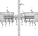
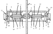
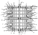
- FIG. 2 is a cross-sectional view showing the configuration of an energy conversion element according to an example embodiment of the present disclosure, in which a low thermal conductivity material is placed in the middle and a magnetic working material is placed on both sides in the same applied magnetic field. A cold portion of one magnetic working material is thermally connected to a hot portion of the other magnetic working material via a heat transfer ring.
- FIG. 3 is a top view showing the configuration of the conversion element with the heat collecting plate removed; A temperature difference output terminal is thermally connected to the heat transfer ring. A ring having a plurality of different temperature regions connected in series such that the temperature of the low temperature state of one magnetic working substance is thermally connected to the high temperature state of the other magnetic working substance within the second identical disc of the present disclosure.
- FIG. 2 is a cross-sectional view showing the structure of an energy conversion element characterized by disposing a magnetic working material in the form of a magnetic material; A cold portion of one magnetic working material is thermally connected to a hot portion of the other magnetic working material via a heat transfer ring.
- FIG. 2 is a cross-sectional view showing the structure of an energy conversion element characterized by disposing a magnetic working material in the form of a magnetic material; A cold portion of one magnetic working material is thermally connected to a hot portion of the other magnetic working material via a magnetic yoke.
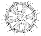
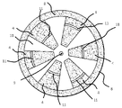
- FIG. 1 is a top view showing the structure of an energy conversion element characterized by disposing a magnetic working material in a shape;
- FIG. A cold portion of one magnetic working material is thermally connected to a hot portion of the other magnetic working material via a magnetic yoke.
- FIG. 3 is a cross-sectional view of an energy conversion element characterized by arranging ring-shaped magnetic working materials having different temperature ranges; A plurality of serially connected magnetic working substances on both sides of the disk composed of the fourth heat insulating material of the present disclosure so that the temperature of the low temperature state of one magnetic working substance is thermally connected to the high temperature state of the other magnetic working substance
- FIG. 2 is a top view of an energy conversion element characterized by arranging ring-shaped magnetic working materials having different temperature ranges; Both sides of the disc composed of the fourth and fifth heat insulating materials of the present disclosure are connected in series so that the temperature of the low temperature state of one magnetic working material is thermally connected to the high temperature state of the other magnetic working material.
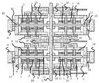
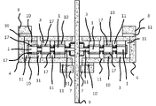
- FIG. 10 is a cross-sectional view of a laminated element in which an element in which ring-shaped magnetic working materials having a plurality of different temperature regions are arranged is further laminated, and a heat exchanger is installed also at the laminated junction portion of the element.
- FIG. 4 is a cross-sectional view showing the configuration of an energy conversion element using a rotating disk-shaped magnetic working material;
- FIG. 2 is a cross-sectional view showing the configuration of an energy conversion element according to an example embodiment of the present disclosure, in which a low thermal conductivity material is placed in the middle and a magnetic working material is placed on both sides in the same applied magnetic field. A cold portion of one magnetic working material is thermally connected to a hot portion of the other magnetic working material via a heat transfer ring.
- FIG. 2 is a cross-sectional view showing the structure of an energy conversion element characterized by disposing a magnetic working material in the form of a magnetic material; A cold portion of one magnetic working material is thermally connected to a hot portion of the other magnetic working material via a magnetic yoke.
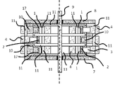
- the left side of the dashed line is the cross section when the low temperature output is installed in the top and bottom stages, and the right side of the dashed line is the cross section when the high temperature output is installed in the top and bottom stages.
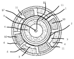
- An upper surface of an energy conversion element characterized by using a ferromagnetic material for the material constituting the third rotating cylinder of the present disclosure and forming a part of a magnetic circuit by a magnet applied to heat a magnetic working material.
- FIG. 4 is a cross-sectional view of a permanent magnet portion; An energy conversion element characterized by using a ferromagnetic material for the material constituting the third and fifth rotating cylinders of the present disclosure and forming a part of the magnetic circuit by the magnet applied to heat the magnetic working material.
- FIG. 1 is a cross-sectional view of a laminated assembly
- Magnetic Working Substance In the conventional AMR device, which has been researched and developed as a magnetic refrigeration technology, a particulate magnetic working substance is used to cause the refrigerant to reciprocate in this gap.
- a magnetic working material with a shape or a conical shape is used.
- a high-temperature output terminal having a strong magnetic field that heats the magnetic working material and a low-temperature output terminal that has a weak magnetic field that does not apply a magnetic field or does not heat the magnetic working material are provided by sandwiching the rotating magnetic working material between the rotating shafts.
- Gd gadolinium
- Mn manganesese
- La lanthanum
- a magnetic field is applied by installing a magnetic field applying unit that is attached to the rotary shaft and includes a permanent magnet necessary to heat the magnetic working material in a manner that sandwiches the rotating magnetic working material.
- a liquid or a liquid in which fine particles are dispersed is introduced between the magnetic working material and the magnetic field applying section.
- a magnetic fluid can be used as the liquid or the liquid in which fine particles are dispersed. Even if the magnetic working material rotates, the magnetic fluid is attracted to the magnetic field and stays in the magnetic field applying portion.
- the magnetization directions of the magnetic working material are aligned by applying a magnetic field, the magnetic working material generates heat. This heat is transferred to the magnetic field application section through the liquid or the liquid in which fine particles are dispersed, and the magnetic field application section itself becomes a high-temperature output terminal, and high-temperature heat can be extracted from the magnetic field application section (Fig. 9).
- Low temperature output terminal A magnetic working material coming out of a strong magnetic field is cooled because the direction of magnetization becomes random.
- a low-temperature output terminal is installed to transfer the heat of the low-temperature state to the outside.
- the cold output terminal does not apply a magnetic field or has a weak magnetic field between the gaps sandwiching the magnetic working material that does not heat the magnetic working material.
- the magnetic working material and the low-temperature output terminal are heat-conducted by a liquid or a liquid in which fine particles are dispersed (Fig. 9).
- Permanent magnets are installed on the rotating shaft so as to create a weak magnetic field of about 0.03 T in the form of sandwiching a rotating disc-shaped magnetic working material. A ferrofluid is introduced between the magnetic working material and the weak magnet.
- the magnetic fluid is attracted to the magnetic field and stays in the magnet part.
- the magnetite magnetic powder used for magnetic fluid is strongly attracted to the magnet even if it is about 0.03 T, and stays on the magnet part even if the magnetic working material rotates.
- the magnetization directions of the magnetic working material are not sufficiently aligned, and the magnetic working material does not generate sufficient heat and is kept in a low temperature state. This low temperature is conducted through the ferrofluid to the magnet, and the magnet portion itself becomes the cold output terminal, through which other substances can be cooled.
- the magnetic fluids filled in the high-temperature output terminal and the low-temperature output terminal, respectively, are attracted by their respective magnets and can maintain their high and low temperature states, respectively, without intermingling with each other (Fig. 9).
- a low thermal conductivity material may be placed between the high temperature output terminal and the low temperature output terminal to more positively prevent the magnetic fluids from intersecting each other.
- rotation of the magnetic working material has been shown so far, it may be a reciprocating motion between a high temperature output terminal and a low temperature output terminal.
- Multi-pair thermal output terminal Multiple pairs of temperature difference output terminals can be installed on the same magnetic working material (Figs. 2, 5, 7, 13). By installing multiple pairs of temperature difference output terminals on the same magnetic working material, the magnetic working material will repeat high magnetic field and low magnetic field with less rotation speed, and the temperature difference generated per rotation of the magnetic working material will be Heat will increase.
- the low temperature output terminal and the high temperature output terminal may be fan-shaped, arc-shaped, or cylindrical, respectively, following the shape of the magnetic working material.
- Magnetic Working Materials in Two Temperature Regions in Same Magnetic Field In order to expand the temperature difference, the elements are laminated. In order to obtain a wide temperature difference, it is necessary to increase the number of stacked layers. However, since a magnetic field applying device is required for each magnetic working material, the number of magnetic field applying devices required increases when the temperature difference is increased.
- a disk having a structure in which magnetic working materials are arranged on both sides with a low thermal conductivity material in the middle is placed in the same magnetic field, and a magnetic field is applied to this disc. By placing a low thermal conductivity material between the terminals, independent temperatures of the magnetic working material can be placed in the same magnetic field.
- a heat transfer ring is installed on the outer periphery to serially connect the temperature differences generated by each magnetic working material.
- the low-temperature part of one magnetic working material and the high-temperature part of the other magnetic working material become the same temperature through the heat transfer ring, so that the temperature difference obtained for a set of applied magnetic fields is approximately double. can do.
- the operating temperature was increased by arranging the magnetic working material on both sides of the disk-shaped heat insulating material.
- Fig. 3 A disk-shaped magnetic working material is divided into rings sandwiching a heat insulating material.
- the magnetic yoke is also provided with heat insulating material to enable independent temperature operation within the same disk surface.
- the operating temperature can be extended within the same disk plane.
- the relative speed of the magnetic working material ring on the inner circumference side is lower than that on the outer circumference side, but by adjusting the ring width, the amount of heat generated can be made uniform.
- a disk shape is shown, but a conical shape or a cylindrical shape may be used instead of the disk shape.
- the technique of using a heat transfer ring in thermally joining different magnetic working materials was described.
- the same magnetic yoke is provided with a place where the applying magnet is installed and a place where it is not installed.
- the magnetic working material generates heat at the location where the applied magnet is installed and becomes a high-temperature output terminal, but the magnetic working material does not generate heat at the location where the impressed magnet is not installed, so it becomes a low-temperature output terminal.
- the low temperature state of one magnetic working substance and the high temperature state of the other magnetic working substance can be achieved. can be thermally connected.
- the cold output of the inner magnetic working material is thermally connected to the high temperature output of the intermediate magnetic working material through the magnetic yoke, and the cold output of the intermediate magnetic working material is connected to the high temperature output of the outer magnetic working material and the magnetic yoke. is thermally connected through In this way, it is possible to expand the temperature difference in three steps within the same disk.
- the hot output terminal is placed in close proximity to the cold output terminal, so if the magnetic fluid is placed for thermal connection, the magnetic fluid may be attracted to a stronger magnetic field, so the cold output terminal , thermal connection can be made not by magnetic fluid but by liquid or liquid in which fine particles are dispersed.
- a disk-shaped example was shown. Since an attractive force acts between the magnetic working material and the magnet for applying a magnetic field, it is necessary to ensure the strength of the disk.
- an example of a cylindrical type that can secure more mechanical strength is shown.
- a ring-shaped magnetic working material is placed around a cylindrical heat insulating material, and a magnetic field is applied from this circumference by a permanent magnet to generate heat in the magnetic working material (Figs. 12 and 13).
- the outer circumference of the cylinder and the portion in contact with the magnetic working material are used as heat insulating material in order to retain the heat generated by the magnetic working material.
- this yoke can be installed inside a rotating cylinder.
- a ferromagnetic material preferably a ferrous material
- the rotating cylinder becomes part of the magnetic circuit at the same time, thereby reducing the magnetic resistance.
- a high-temperature output terminal and a low-temperature output terminal including a magnetic field applying device are alternately arranged around the cylinder.
- the polarity of the magnetic field is not set to the same NS direction between the high temperature output terminals, but the polarity of the magnetic field is changed between the adjacent high temperature output terminals via the low temperature output terminal, so that the An efficient magnetic circuit can be constructed including the magnetic yoke installed in the
- ⁇ 4 Fourth Embodiment> By combining 1 and 2 above, it is possible to further increase the operating temperature.
- the operating temperature By arranging multiple ring-shaped magnetic working substances on both sides of a disk made of heat insulating material and thermally connecting these magnetic working substances in series, the operating temperature can be further expanded (Fig. 6). From these methods, the optimum method can be selected according to the required characteristics such as temperature difference, heat quantity, weight, volume, etc. of the required cooling device.
- the magnetic working material used in each element need not be the same.
- the temperature difference can be increased. An attractive force is generated between the magnetic working material and the applied magnet.
- the disk In order to increase the strength of the disk, the disk may be made of metal and the surface thereof may be a heat insulating material.
- a conical shape or a cylindrical shape may be used instead of the disk shape.
- the temperature difference can be increased by connecting the energy conversion elements in series. By connecting the low temperature output terminal and the high temperature output terminal of the separate element with good thermal conductivity, the low temperature output terminal and the high temperature output terminal are at the same temperature. As a result, the temperature difference further increases between the output terminals on the unconnected side (Figs. 8 and 14). Although an example of two-stage connection is shown here, the number of laminations can be similarly increased as necessary to obtain a desired temperature difference. At this time, the magnetic working material used for each stacked element need not be the same. By arranging magnetic working materials with different optimum operating temperatures according to the operating temperature of each element, the temperature difference can be increased.
- Multiple temperature range output When stacking elements, heat exchangers can also be installed at the joints (Figs. 8 and 14). This allows multiple temperatures to be output. By adjusting the amount of heat medium introduced into the heat exchanger in each temperature range, the output heat quantity in each temperature range can be adjusted independently.
- the elements are connected in series with a difference in temperature. Further, if these elements are connected in series to increase the operating temperature difference, they can be used for applications such as air conditioners and refrigerators. Rotational kinetic energy can be directly converted into temperature difference energy, and conversion energy loss is small. Furthermore, as described in 5 above, heat output in a plurality of temperature ranges is easily possible from the joints of the laminated elements, so multiple heat output temperature control devices such as cooling and heating, freezing and refrigerating can be easily realized. . Because of its low noise, it can also be used for refrigerators and freezers in hotel rooms.
- Example 1 A stainless steel shaft with a diameter of 5 mm and a length of 50 mm was prepared. A magnetic working material Gd (gadolinium) with a thickness of 0.8 mm was adhered to a 20-mm upper and lower peripheral portion of a disk-shaped polycarbonate with a thickness of 1.5 mm and a diameter of 40 mm. The center of this disc was fixed to the stainless steel shaft. The rotation of the shaft also rotates the magnetic working material. In order to apply a magnetic field to the magnetic working material, permanent magnets with yokes were installed so as to sandwich the disk-shaped magnetic working material. NdFeB magnets were used as permanent magnets, and the gap was set to 5.5 mm.
- Gd gadolinium
- the magnetic flux between gaps was set to 0.9T.
- a heat insulator was installed in the middle of the yoke to keep the temperature independent of the top and bottom of the yoke.
- a magnetic fluid consisting of magnetite magnetic powder was filled between the magnetic working material and the permanent magnet to form a high-temperature output terminal (Fig. 1).
- a permanent magnet with a yoke was installed so as to sandwich the disk-shaped magnetic working material.
- Sr-Ferrite magnets were used as permanent magnets, and the gap was set to 5.5 mm.
- the magnetic flux between gaps was set to 0.03T.
- a heat insulator was installed in the middle of the yoke to keep the temperature independent of the top and bottom of the yoke.
- a magnetic fluid consisting of magnetite magnetic powder was filled between the magnetic working material and the permanent magnet to form a low-temperature output terminal (Fig. 1).
- a heat transfer ring was installed on the outer circumference in order to connect the temperature difference between the upper and lower magnetic working materials in series. A low-temperature portion of one magnetic working material and a high-temperature portion of the other magnetic working material are thermally connected via a heat transfer ring and have similar temperatures.
- the room temperature and initial element temperature were set to 23.0°C, the shaft was rotated at 5 rpm, and after 5 minutes, the temperatures of the high temperature output terminal and the low temperature output terminal at both ends of the energy conversion element were measured.
- the temperatures of the high temperature output terminal and the low temperature output terminal at both ends were 24.8°C and 21.2°C, respectively.
- a pair of applied magnetic fields produces a temperature difference equivalent to two steps.
- Comparative example 1 A stainless steel shaft with a diameter of 5 mm and a length of 50 mm was prepared.
- the disk-shaped magnetic working material also rotates due to the rotation of the shaft.
- Gd (gadolinium) has a thermal conductivity of about 10.6 W/mK (300 K), whereas polycarbonate has a significantly lower thermal conductivity of about 0.19 W/mK (300 K). The heat conduction of the part not passing through the magnetic field decreased (Fig. 9).
- a permanent magnet with a yoke was installed to sandwich the disk-shaped magnetic working material.
- NdFeB magnets were used as permanent magnets, and the gap was set to 4.0 mm.
- the magnetic flux between gaps was set to 0.9T.
- a magnetic fluid consisting of magnetite magnetic powder is filled between the magnetic working material and the permanent magnet to form a high-temperature output terminal.
- a permanent magnet with a yoke was installed so as to sandwich the disk-shaped magnetic working material.
- Sr-Ferrite magnets were used as permanent magnets, and the gap was set to 4.0 mm.
- the magnetic flux between gaps was set to 0.03T.
- a magnetic fluid consisting of magnetite magnetic powder was filled between the magnetic working material and the permanent magnet to form a low-temperature output terminal (Fig. 9).
- the room temperature and element constituent materials were all initially set to 23.0°C.
- the disk-shaped magnetic working material fixed to the shaft was rotated by the rotation of the shaft.
- the rotation speed was 5 rpm. It was confirmed that the magnetic fluid is fixed by the high temperature output terminal and the low temperature output terminal and does not move even when the magnetic working material rotates.
- the temperature was measured 3 minutes after the start of rotation of the shaft, it was observed to be 24.0°C at the high temperature output terminal and 22.0°C at the low temperature output terminal.
- Example 2 A stainless steel shaft with a diameter of 5 mm and a length of 50 mm was prepared. A ring-shaped magnetic working material Gd (gadolinium) with a thickness of 1.5 mm and a ring-shaped heat insulating material with a thickness of 1.0 mm were combined to form a disk (Fig. 6). Each magnetic working material operates in an independent temperature range. The center of this disc was fixed to the stainless steel shaft. The rotation of the shaft also rotates the magnetic working material. In order to apply a magnetic field to the magnetic working material, a plurality of permanent magnets with yokes were installed so as to sandwich the disk-shaped magnetic working material.
- Gd gallium
- a ring-shaped heat insulating material with a thickness of 1.0 mm
- NdFeB magnets were used as permanent magnets, and the gap was set to 4.0 mm. The magnetic flux between gaps was set to 0.9T. Insulation was placed within the yoke to maintain multiple independent temperatures within the yoke. A magnetic fluid consisting of magnetite magnetic powder was filled between the magnetic working material and the permanent magnet to form a high-temperature output terminal (Fig. 3). Three high-temperature output terminals were installed at equal intervals on the same disc.
- a permanent magnet with a yoke was installed so as to sandwich the disc.
- a plurality of Sr-Ferrite magnets were used as permanent magnets, and the gap was set to 4.0 mm.
- the magnetic flux between gaps was set to 0.03T.
- Insulation was installed in the middle of the yoke to maintain an independent temperature within the yoke.
- a magnetic fluid consisting of magnetite magnetic powder was filled between the magnetic working material and the permanent magnet to form a low-temperature output terminal (Fig. 3).
- Fig. 3 As with the high temperature output terminals, three low temperature output terminals were installed on the same disk to form multiple input/output terminals.
- Heat transfer rings were placed above and below the disk to connect the temperature differences between the magnetic working materials in the disk in series. A low-temperature portion of one magnetic working material and a high-temperature portion of the other magnetic working material are thermally connected via a heat transfer ring and have similar temperatures. One connection ring thermally connects three high temperature output terminals and three low temperature output terminals.
- the room temperature and initial element temperature were set to 23.0°C, the shaft was rotated at 5 rpm, and after 5 minutes, the temperatures of the high temperature output terminal and the low temperature output terminal at both ends of the energy conversion element were measured.
- the temperatures of the high temperature output terminal and the low temperature output terminal at both ends were 25.7°C and 20.3°C, respectively.
- a temperature difference close to equivalent to three steps can be obtained with one element.
- Example 3 A magnetic working substance and a heat insulating material composite disk similar to those in Example 2 were prepared and fixed to a shaft similar to that in Example 2.
- a plurality of permanent magnets with yokes were installed so as to sandwich the ring-shaped magnetic working material.
- a high-temperature output terminal and a low-temperature output terminal were alternately arranged between the magnetic yoke and the magnetic working material with and without NeFeB permanent magnets.
- a heat insulating resin was introduced into the gap. Liquid heat conduction is assumed between the low-temperature output terminal and the ring-shaped magnetic working material.
- a magnetic fluid was introduced between the high-temperature output terminal and the ring-shaped magnetic working material to serve as a heat conductor. Even if the magnetic working material rotates, the magnetic fluid stays in the NeFeB system permanent magnet and is not diffused.
- a heat insulating material placed within the magnetic yoke provides a thermal series connection through the magnetic yoke such that the cold state temperature of one magnetic working material is thermally connected to the hot state temperature of the other magnetic working material.
- Three low-temperature output terminals and high-temperature output terminals were installed on the same disk to form multiple input/output terminals (Figs. 4 and 5).
- the room temperature and initial element temperature were set to 23.0° C., the shaft was rotated at 5 rpm, and the temperatures of the high temperature output terminal and the low temperature output terminal at both ends of the energy conversion element were measured after 5 minutes.
- the temperatures of the high temperature output terminal and the low temperature output terminal at both ends were 25.5°C and 20.5°C, respectively.
- Example 4 A stainless steel shaft with a diameter of 5 mm and a length of 50 mm was prepared. A cylindrical polycarbonate with a height of 8 mm and a diameter of 20 mm is placed around the axis, and a ring-shaped iron-based magnetic yoke material is placed around it. did. This cylinder was fixed to a stainless steel shaft as a three-tiered stack via polycarbonate discs. As the shaft rotates, so does the cylinder (Figs. 12, 13).
- a plurality of permanent magnets with yokes were installed so as to sandwich the ring-shaped magnetic working material.
- a NeFeB system permanent magnet was installed between the magnetic yoke and the magnetic working material as a high temperature output terminal. Places with permanent magnets and places without permanent magnets were alternately arranged to form a high-temperature output terminal and a low-temperature output terminal, respectively.
- a heat insulating resin was introduced into the gap.
- a ferrofluid was introduced between the high temperature output terminal and the magnetic working material.
- the magnetic fluid stays between the high-temperature output terminal and the magnetic working material due to the force of the magnetic field even when the cylinder containing the magnetic working material rotates, and conducts the heat generated by the application of the magnetic field to the high-temperature output terminal. Liquid heat conduction is assumed between the low-temperature output terminal and the ring-shaped magnetic working material.
- An iron-based magnetic yoke is introduced inside the cylinder.
- a magnetic circuit is formed with high-temperature output terminals having different magnetic polarities through the cylinder and the magnetic yoke material installed on the outer circumference.
- the permanent magnet for applying a magnetic field of 0.9 T is a NeFeB-based permanent magnet that weighs 20% less when the iron-based magnetic yoke is introduced inside the cylinder. It turned out that the introduction amount was sufficient.
- the temperature of the low temperature state of one magnetic working material is thermally connected to the high temperature state of the other magnetic working material. series connection.
- the middle high-temperature output terminal in FIG. 21 is thermally connected to the lower low-temperature output terminal through a heat transfer material, and the middle low-temperature output terminal is thermally connected to the upper high-temperature output terminal. In this way, it is possible to thermally connect in series on the same cylinder.
- the room temperature and initial element temperature were set to 23.0° C., the shaft was rotated at 5 rpm, and the temperatures of the high temperature output terminal and the low temperature output terminal at both ends of the energy conversion element were measured after 5 minutes.
- the temperatures of the high temperature output terminal and the low temperature output terminal at both ends were 25.5°C and 20.5°C, respectively.
- Example 5 A stainless steel shaft with a diameter of 5 mm and a length of 50 mm was prepared. A 1.5 mm-thick disc-shaped polycarbonate, and 0.8 mm-thick ring-shaped magnetic working material Gd (gadolinium) were independently adhered to the upper and lower parts, 3 rings each for a total of 6 rings. The center of this disc was fixed to the stainless steel shaft. The rotation of the shaft also rotates the magnetic working material. In order to apply a magnetic field to the magnetic working material, permanent magnets with yokes were installed so as to sandwich the disk-shaped magnetic working material. NdFeB magnets were used as permanent magnets, and the gap was set to 5.5 mm.
- Gd gadolinium
- the magnetic flux between gaps was set to 0.9T.
- a heat insulating material was installed inside the yoke.
- a magnetic fluid consisting of magnetite magnetic powder was filled between the magnetic working material and the permanent magnet to form a high-temperature output terminal (Figs. 6 and 7).
- Three high-temperature output terminals were installed at equal intervals on the same disc.
- a permanent magnet with a yoke was installed so as to sandwich the disc.
- a plurality of Sr-Ferrite magnets were used as permanent magnets, and the gap was set to 5.5 mm.
- the magnetic flux between gaps was set to 0.03T.
- a heat insulating material was installed inside the yoke.
- a magnetic fluid consisting of magnetite magnetic powder was filled between the magnetic working material and the permanent magnet to form a low-temperature output terminal (Figs. 6 and 7).
- three low temperature output terminals were installed on the same disk to form multiple input/output terminals.
- Heat transfer rings were placed above and below the disk to connect the temperature differences between the magnetic working materials in the disk in series.
- a low-temperature portion of one magnetic working material and a high-temperature portion of the other magnetic working material are thermally connected via a heat transfer ring and have similar temperatures.
- One connection ring thermally connects three high-temperature output terminals on the top and bottom and three low-temperature output terminals on the top and bottom.
- a heat transfer ring was installed around the perimeter in order to connect the temperature differences between the upper and lower magnetic working materials in series.
- a low-temperature portion of one magnetic working material and a high-temperature portion of the other magnetic working material are thermally connected via a heat transfer ring and have similar temperatures.
- the room temperature and initial element temperature were set to 23.0° C., the shaft was rotated at 5 rpm, and the temperatures of the high temperature output terminal and the low temperature output terminal at both ends of the energy conversion element were measured after 5 minutes.
- the temperatures of the high temperature output terminal and the low temperature output terminal at both ends were 27.8°C and 18.2°C, respectively.
- a temperature difference close to 6 steps can be obtained with one element.
- Example 6 In the energy conversion elements shown so far, the temperature difference generated can be expanded by connecting the high temperature part of one element and the low temperature part of the other element thermally and connecting them in series. By installing heat exchangers in the low-temperature part and the high-temperature part of this laminated element, it is possible to easily output heat at an intermediate temperature (Figs. 8 and 14).
- the heat-insulating disk double-sided composite element shown in Example 5 was laminated to expand the temperature difference region. At this time, heat exchangers were installed not only at the low temperature output part and the high temperature output part, but also at the joints. This results in multiple heat outputs (Fig. 8).
- Gd Gdolin
- other magnetic working materials can be adopted depending on the required temperature range, and the composition of the magnetic working material in the stack and in the element can be changed and a magnetic working material suitable for that temperature can be used.
- Example 7 A temperature control device having multiple temperature outputs is obtained using the multi-heat exchanger stacked element. Using the energy conversion element assembly shown in FIG. 8, the heat exchanger connected to the high temperature output terminal was set to 23° C. with cooling water. The shaft was rotated at 5 rpm, and the temperature of the low-temperature output terminal of the energy conversion element laminate assembly was measured after 10 minutes. Here the heat output from the intermediate heat exchanger was 13.6°C and the heat output from the heat exchanger connected to the cold output terminal was 4.4°C. A device capable of cooling at multiple temperatures was obtained with only one laminated element. Although an example of a cooling device is shown here, a heating device capable of outputting a plurality of temperatures or a device capable of heating at the same time as cooling can be constructed.
- the high temperature output terminal can be connected to a radiator for heat dissipation through a heat exchanger or the like, and the low temperature output terminal can be connected to a required cooling system through a heat exchanger or the like.
- a heating system can be constructed in the same way. Since it is possible to output at multiple temperatures, it is possible to construct a cooling and heating device, or a cooling or heating device based on multiple temperature ranges. For this reason, it can be applied with high performance to various heating or cooling systems such as refrigerators and air conditioners that directly generate high and low temperatures from various transportation equipment such as automobiles that generate kinetic energy, and natural energy conversion devices such as water turbines and windmills.
Landscapes
- Engineering & Computer Science (AREA)
- Power Engineering (AREA)
- Physics & Mathematics (AREA)
- Electromagnetism (AREA)
- Mechanical Engineering (AREA)
- Thermal Sciences (AREA)
- General Engineering & Computer Science (AREA)
- Dynamo-Electric Clutches, Dynamo-Electric Brakes (AREA)
- Soft Magnetic Materials (AREA)
Abstract
Les problèmes décrits par la présente invention est : de fournir un élément de conversion d'énergie pour convertir l'énergie cinétique en énergie de différence de température, l'élément de conversion d'énergie ayant une structure simple qui ne génère pas de bruit ou de vibration ; d'augmenter une largeur de différence de température générée ; et de construire un dispositif de régulation de température à gestion de température multiple à l'aide d'un élément en couches de conversion d'énergie. La solution selon l'invention est qu'un matériau de travail magnétique en forme d'anneau et de disque rotatif, et qu'une partie qui applique un champ magnétique à celui-ci soient thermiquement joints à l'aide d'un ferrofluide, et la quantité de chaleur générée par le champ magnétique est induite à une partie d'aimant permanent. En outre, une partie d'état froid est également reliée thermiquement à une borne de sortie à basse température par le fluide. Par conséquent, une partie à haute température et une partie à basse température peuvent être produites par rotation du matériau de travail magnétique en forme d'anneau et de disque. Le matériau de travail magnétique est thermiquement connecté en série à l'intérieur de l'élément, ce qui permet d'augmenter la différence de température entre une température élevée et une basse température Un échangeur de chaleur est également installé au niveau d'une partie en couches d'élément de conversion d'énergie, ce qui permet de produire de la chaleur dans de multiples régions de température. Il est possible de construire un dispositif de régulation de température à région de température multiple avec un faible bruit et une faible vibration.
Priority Applications (1)
| Application Number | Priority Date | Filing Date | Title |
|---|---|---|---|
| US18/260,243 US20240388225A1 (en) | 2021-01-19 | 2021-01-01 | Energy conversion element and temperature regulator using the same |
Applications Claiming Priority (4)
| Application Number | Priority Date | Filing Date | Title |
|---|---|---|---|
| JP2021-006491 | 2021-01-19 | ||
| JP2021006491 | 2021-01-19 | ||
| JP2021097168A JP7037688B1 (ja) | 2021-01-19 | 2021-06-10 | エネルギー変換素子およびこれを用いた温度調節装置 |
| JP2021-097168 | 2021-06-10 |
Publications (1)
| Publication Number | Publication Date |
|---|---|
| WO2022158282A1 true WO2022158282A1 (fr) | 2022-07-28 |
Family
ID=81213592
Family Applications (1)
| Application Number | Title | Priority Date | Filing Date |
|---|---|---|---|
| PCT/JP2022/000002 Ceased WO2022158282A1 (fr) | 2021-01-19 | 2022-01-01 | Élément de conversion d'énergie et dispositif de régulation de température l'utilisant |
Country Status (3)
| Country | Link |
|---|---|
| US (1) | US20240388225A1 (fr) |
| JP (1) | JP7037688B1 (fr) |
| WO (1) | WO2022158282A1 (fr) |
Families Citing this family (1)
| Publication number | Priority date | Publication date | Assignee | Title |
|---|---|---|---|---|
| US12475917B1 (en) * | 2024-05-17 | 2025-11-18 | The Regents Of The University Of California | Devices and methods for degaussing magnetic recording storage media |
Citations (8)
| Publication number | Priority date | Publication date | Assignee | Title |
|---|---|---|---|---|
| JPS6326312B2 (fr) * | 1984-11-13 | 1988-05-28 | Ryozo Aoki | |
| JP2569059B2 (ja) * | 1986-07-11 | 1997-01-08 | 株式会社日立製作所 | 磁気冷凍装置および方法 |
| JP2008249175A (ja) * | 2007-03-29 | 2008-10-16 | Toshiba Corp | 磁気冷凍デバイス及び磁気冷凍方法 |
| JP4557874B2 (ja) * | 2005-11-30 | 2010-10-06 | 株式会社東芝 | 磁気冷凍機 |
| JP5060602B2 (ja) * | 2010-08-05 | 2012-10-31 | 株式会社東芝 | 磁気冷凍デバイスおよび磁気冷凍システム |
| JP5656180B1 (ja) * | 2013-03-12 | 2015-01-21 | 藤田 恵三 | 感温磁性材料を用いた回転駆動装置 |
| JP2020169806A (ja) * | 2019-04-04 | 2020-10-15 | 香取 健二 | エネルギー変換素子およびこれを用いた温度調節装置 |
| JP2020174516A (ja) * | 2019-04-11 | 2020-10-22 | 香取 健二 | エネルギー変換素子 |
Family Cites Families (1)
| Publication number | Priority date | Publication date | Assignee | Title |
|---|---|---|---|---|
| JP6326312B2 (ja) | 2014-07-14 | 2018-05-16 | 株式会社ジャパンディスプレイ | 表示装置 |
-
2021
- 2021-01-01 US US18/260,243 patent/US20240388225A1/en not_active Abandoned
- 2021-06-10 JP JP2021097168A patent/JP7037688B1/ja active Active
-
2022
- 2022-01-01 WO PCT/JP2022/000002 patent/WO2022158282A1/fr not_active Ceased
Patent Citations (8)
| Publication number | Priority date | Publication date | Assignee | Title |
|---|---|---|---|---|
| JPS6326312B2 (fr) * | 1984-11-13 | 1988-05-28 | Ryozo Aoki | |
| JP2569059B2 (ja) * | 1986-07-11 | 1997-01-08 | 株式会社日立製作所 | 磁気冷凍装置および方法 |
| JP4557874B2 (ja) * | 2005-11-30 | 2010-10-06 | 株式会社東芝 | 磁気冷凍機 |
| JP2008249175A (ja) * | 2007-03-29 | 2008-10-16 | Toshiba Corp | 磁気冷凍デバイス及び磁気冷凍方法 |
| JP5060602B2 (ja) * | 2010-08-05 | 2012-10-31 | 株式会社東芝 | 磁気冷凍デバイスおよび磁気冷凍システム |
| JP5656180B1 (ja) * | 2013-03-12 | 2015-01-21 | 藤田 恵三 | 感温磁性材料を用いた回転駆動装置 |
| JP2020169806A (ja) * | 2019-04-04 | 2020-10-15 | 香取 健二 | エネルギー変換素子およびこれを用いた温度調節装置 |
| JP2020174516A (ja) * | 2019-04-11 | 2020-10-22 | 香取 健二 | エネルギー変換素子 |
Also Published As
| Publication number | Publication date |
|---|---|
| US20240388225A1 (en) | 2024-11-21 |
| JP2022111021A (ja) | 2022-07-29 |
| JP7037688B1 (ja) | 2022-03-16 |
Similar Documents
| Publication | Publication Date | Title |
|---|---|---|
| AU2008346318B2 (en) | Thermal generator with magneto-caloric material | |
| EP2420761B1 (fr) | Dispositif de réfrigération magnétique et système de réfrigération magnétique | |
| US9273886B2 (en) | Magnetic refrigerator utilizing a permanent magnet to create movement between plates comprising high and low temperature side heat exchangers | |
| CN101979937B (zh) | 一种旋转式磁制冷装置及其应用 | |
| US4956976A (en) | Magnetic refrigeration apparatus for He II production | |
| US20120060513A1 (en) | Magnetocaloric refrigerator | |
| JP2008082663A (ja) | 磁気冷凍デバイスおよび磁気冷凍方法 | |
| CN103795224B (zh) | 一种超导隔磁式调磁装置 | |
| CN112254370B (zh) | 基于热电磁耦合的全固态能量转换制冷器件 | |
| JP2007147209A (ja) | 磁気冷凍機 | |
| CN103808061A (zh) | 磁制冷装置和磁制冷系统 | |
| JP2008082662A (ja) | 磁気冷凍デバイスおよび磁気冷凍方法 | |
| CN103782116A (zh) | 磁性构造体及使用其的磁制冷制热装置 | |
| CN106931687B (zh) | 一种用于室温磁制冷的串联微元回热系统 | |
| JP6960492B2 (ja) | エネルギー変換素子およびこれを用いた温度調節装置 | |
| JP2014095535A (ja) | 磁気冷暖房装置 | |
| JP2015124927A (ja) | 熱磁気サイクル装置 | |
| JP5807723B2 (ja) | 磁気冷暖房装置 | |
| CN106931688B (zh) | 一种用于室温磁制冷的并联微元回热系统 | |
| CN206618168U (zh) | 一种用于室温磁制冷的串联微元回热系统 | |
| US20100146989A1 (en) | Continuously rotary magnetic refrigerator or heat pump | |
| JP7037688B1 (ja) | エネルギー変換素子およびこれを用いた温度調節装置 | |
| CN113494785B (zh) | 一种全固态磁制冷器件及其使用方法和应用 | |
| KR101204325B1 (ko) | 콤팩트한 능동형 자기 재생식 냉동기 | |
| CN206695450U (zh) | 一种用于室温磁制冷的并联微元回热系统 |
Legal Events
| Date | Code | Title | Description |
|---|---|---|---|
| 121 | Ep: the epo has been informed by wipo that ep was designated in this application |
Ref document number: 22742407 Country of ref document: EP Kind code of ref document: A1 |
|
| WWE | Wipo information: entry into national phase |
Ref document number: 18260243 Country of ref document: US |
|
| NENP | Non-entry into the national phase |
Ref country code: DE |
|
| 122 | Ep: pct application non-entry in european phase |
Ref document number: 22742407 Country of ref document: EP Kind code of ref document: A1 |