WO2022158352A1 - 折曲げ加工方法 - Google Patents
折曲げ加工方法 Download PDFInfo
- Publication number
- WO2022158352A1 WO2022158352A1 PCT/JP2022/000749 JP2022000749W WO2022158352A1 WO 2022158352 A1 WO2022158352 A1 WO 2022158352A1 JP 2022000749 W JP2022000749 W JP 2022000749W WO 2022158352 A1 WO2022158352 A1 WO 2022158352A1
- Authority
- WO
- WIPO (PCT)
- Prior art keywords
- groove wall
- wall surface
- work
- groove
- die
- Prior art date
- Legal status (The legal status is an assumption and is not a legal conclusion. Google has not performed a legal analysis and makes no representation as to the accuracy of the status listed.)
- Ceased
Links
Images






Classifications
-
- B—PERFORMING OPERATIONS; TRANSPORTING
- B21—MECHANICAL METAL-WORKING WITHOUT ESSENTIALLY REMOVING MATERIAL; PUNCHING METAL
- B21D—WORKING OR PROCESSING OF SHEET METAL OR METAL TUBES, RODS OR PROFILES WITHOUT ESSENTIALLY REMOVING MATERIAL; PUNCHING METAL
- B21D5/00—Bending sheet metal along straight lines, e.g. to form simple curves
- B21D5/02—Bending sheet metal along straight lines, e.g. to form simple curves on press brakes without making use of clamping means
-
- B—PERFORMING OPERATIONS; TRANSPORTING
- B21—MECHANICAL METAL-WORKING WITHOUT ESSENTIALLY REMOVING MATERIAL; PUNCHING METAL
- B21D—WORKING OR PROCESSING OF SHEET METAL OR METAL TUBES, RODS OR PROFILES WITHOUT ESSENTIALLY REMOVING MATERIAL; PUNCHING METAL
- B21D19/00—Flanging or other edge treatment, e.g. of tubes
- B21D19/08—Flanging or other edge treatment, e.g. of tubes by single or successive action of pressing tools, e.g. vice jaws
-
- B—PERFORMING OPERATIONS; TRANSPORTING
- B21—MECHANICAL METAL-WORKING WITHOUT ESSENTIALLY REMOVING MATERIAL; PUNCHING METAL
- B21D—WORKING OR PROCESSING OF SHEET METAL OR METAL TUBES, RODS OR PROFILES WITHOUT ESSENTIALLY REMOVING MATERIAL; PUNCHING METAL
- B21D5/00—Bending sheet metal along straight lines, e.g. to form simple curves
- B21D5/02—Bending sheet metal along straight lines, e.g. to form simple curves on press brakes without making use of clamping means
- B21D5/0209—Tools therefor
-
- B—PERFORMING OPERATIONS; TRANSPORTING
- B21—MECHANICAL METAL-WORKING WITHOUT ESSENTIALLY REMOVING MATERIAL; PUNCHING METAL
- B21D—WORKING OR PROCESSING OF SHEET METAL OR METAL TUBES, RODS OR PROFILES WITHOUT ESSENTIALLY REMOVING MATERIAL; PUNCHING METAL
- B21D5/00—Bending sheet metal along straight lines, e.g. to form simple curves
- B21D5/16—Folding; Pleating
Definitions
- the present invention relates to a bending method for bending a plate-like work.
- a thrust load corresponding to the angle of the sharply bent flange acts on the workpiece.
- a force is generated that pushes the workpiece forward (toward the operator).
- the thrust load acting on the work increases due to the influence of the material, thickness, etc. of the work, the force pushing the work forward increases.
- the workability of the hemming process may deteriorate.
- the workpiece may be misaligned with respect to the die, and the bending accuracy may be lowered.
- a method of creating a dedicated die can be considered to address this problem.
- manufacturing a dedicated die increases the cost.
- the workability of the bending process is lowered.
- a bending method includes a die having a V-groove that can be mounted on a lower table of a press brake and has a first groove wall surface and a second groove wall surface on the upper part, and an upper part of the press brake.
- a first surface parallel to the first groove wall surface of the die which can be mounted on the table and is mounted on the upper table and mounted on the lower table in the work pressing part, and a vertical surface.
- a punch having a second surface whose angle is different from the angle formed by the second groove wall surface and the vertical surface.
- a plate-like work is placed on the upper part of the die mounted on the lower table. The plate-like work is pressed by the work pressing portion of the punch mounted on the upper table of the press brake, and sandwiched between the first groove wall surface of the V groove and the first surface of the punch. It is folded in a folded state.
- FIG. 1A is a side view showing a state in which a die 10 and a punch 30 used in the bending method according to this embodiment are attached to a press brake device 100.
- FIG. FIG. 1B is an enlarged cross-sectional view of the workpiece pressing portion 31 of the punch 30 and the V-groove 12 of the die 10 shown in FIG. 1A.
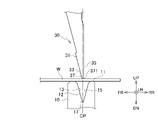
- FIG. 2 is a diagram showing a state in which the workpiece W is positioned and placed on the bending die 10.
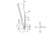
- FIG. 3A and 3B are diagrams showing the process of bending the work W.
- FIG. FIG. 4 is a diagram showing the completed state of the bending of the work W.
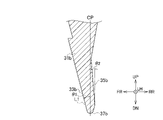
- FIG. 5A is a diagram showing a modification of the present embodiment, and is an enlarged cross-sectional view including the work pressing portion of the punch 31a.
- FIG. 5B is a diagram showing a modification of the present embodiment, and is an enlarged sectional view including the work pressing portion of the punch 31b.
- FIG. 5C is a diagram showing a modification of the present embodiment, and is an enlarged sectional view including the work pressing portion of the punch 31c.
- FIG. 6 is a side view showing a modification of the bending die 50 according to the present embodiment, in which the die 50 is a double-deck die for hemming.
- the "horizontal direction” is one of the horizontal directions and is the width direction when the die and the punch are attached to the press brake (the direction orthogonal to the paper surface in each drawing).
- the “front-back direction” is the depth direction (horizontal direction on the paper surface) when the die and the punch are attached to the press brake.
- the “vertical direction” is a direction perpendicular to the left-right direction and the front-rear direction (vertical direction on the paper surface).
- the forward direction is indicated as "FR”, the rearward direction as "RR”, the leftward direction (front side of the paper) as "LH”, the upward direction as "UP”, and the downward direction as "DN”.
- FIG. 1A is a side view illustrating a state in which a die and a punch used in the bending method according to this embodiment are attached to a press brake device.
- the press brake 100 used in the bending method according to the present embodiment is a press brake for bending a sheet metal work W, which can be used for pre-bending in hemming.
- a lower table 110 extending in the left-right direction is provided at the lower portion of the press brake 100 main body.
- the die 10 is detachably mounted on the upper side of the lower table 110 via a die holder.
- An upper table 130 extending in the horizontal direction is provided on the upper portion of the press brake 100 main body so as to vertically face the lower table 110 and be movable in the vertical direction.
- a punch 30 is detachably attached to the lower side of the upper table 130 via a punch holder.
- the configuration for moving the upper table 130 in the vertical direction may be, for example, the known configuration described in JP-A-2004-98105 and JP-A-2004-34059.
- a table servomotor or a hydraulic cylinder (not shown) may be used to move the upper table 130 in the vertical direction.
- the lower table 110 may be configured to be vertically movable.
- FIG. 1B is an enlarged cross-sectional view of the workpiece pressing portion 31 of the punch 30 and the V groove 12 of the die 10 shown in FIG. 1A.
- the die 10 used in the bending method according to this embodiment has a V-groove 12 with a first groove wall surface 13 and a second groove wall surface 15 in the upper part 11 .
- Die 10 is mounted on lower table 110 of press brake 100 .
- the die 10 has a V-groove 12 extending in the left-right direction (direction perpendicular to the paper surface of FIG. 1A) in the upper portion 11 .
- V-groove 12 includes first groove wall surface 13 and second groove wall surface 15 .
- the V-groove 12 further includes a groove bottom 17 that connects the first groove wall surface 13 and the second groove wall surface 15 and has an arcuate cross-sectional shape perpendicular to the left-right direction.
- first groove wall surface 13 and the second groove wall surface 15 of the V-groove 12 are symmetrical with respect to the first vertical plane CP.
- first vertical plane CP is a vertical plane passing through an intersection position CL where imaginary planes extending downward along the groove wall surfaces 13 and 15 of the V groove 12 intersect. That is, in this embodiment, the groove wall surfaces 13 and 15 of the V-groove 12 have an angle formed by the first groove wall surface 13 and the first vertical plane CP and an angle formed by the second groove wall surface 15 and the first vertical plane CP.
- the cross-sectional shape of the groove bottom 17 perpendicular to the left-right direction is arc-shaped, so the first vertical plane CP is a vertical plane passing through the arc-shaped center of the groove bottom 17 .
- the angle ⁇ v formed by the first groove wall surface 13 and the second groove wall surface 15 of the V-groove 12 is an acute angle. Specifically, the angle ⁇ v between the first groove wall surface 13 and the second groove wall surface 15 of the V-groove 12 is 30°. At this time, the angle between the first groove wall surface 13 and the first vertical plane CP and the angle between the second groove wall surface 15 and the first vertical plane CP are 15° ( ⁇ v/2).
- this angle ⁇ v may be set according to the material and thickness of the work to be bent, or the purpose of the bending.
- the angle ⁇ v may range, for example, from 30° to 90°.
- the first groove wall surface 13 and the second groove wall surface 15 of the V-groove 12 are flat on the groove bottom 17 side of the V-groove 12 and curved as a ridge line R on the upper portion 11 side. , smoothly connecting to the upper part 11 .
- the punch 30 used for bending according to this embodiment is mounted on the upper table 130 of the press brake 100 so as to be able to enter the V-groove 12 of the die 10, as shown in FIG. 1A.
- the punch 30 has a workpiece pressing portion 31 that enters the V-groove 12 .
- the punch 30 is configured to advance and retreat with respect to the V-groove 12 by moving the upper table 130 vertically while being mounted on the upper table 130 .
- the work pressing portion 31 of the punch 30, when mounted on the upper table 130, has a first surface 33 and a second surface 35 positioned on the upper side, and upper and lower surfaces positioned on the lower side. It has a tip portion 37 that is continuous with the lower end of each of the first surface 33 and the second surface 35 at a predetermined position L1 in the direction.
- the first surface 33 When attached to the upper table 130, the first surface 33 is positioned on the first side FS with respect to the first vertical plane CP (the left side of the first vertical plane CP in FIG. 1B).
- the second surface 35 is located on the second side SS (the right side of the first vertical plane CP in FIG. 1B) with respect to the first vertical plane CP.
- the first surface 33 is parallel to the first groove wall surface 13 of the die 10 mounted on the lower table 110 .
- the angle ⁇ 2 formed between the second surface 35 and a vertical plane parallel to the first vertical plane CP including the horizontal direction is different from the angle ⁇ v/2 formed between the second groove wall surface 15 and the first vertical plane CP.
- the angle ⁇ 1 of the first surface 33 is 15° and the angle ⁇ 2 of the second surface 35 is 0°. That is, when the punch 30 is mounted on the upper table 130, the first surface 33 is inclined by 15° to the first side FS with respect to the first vertical plane CP. Therefore, the first surface 33 is parallel to the first groove wall surface 13 of the V-groove 12 .
- the second surface 35 connects with the tip portion 37 on the second side SS and is parallel to the first vertical surface CP.
- the tip portion 37 of the punch 30 is formed symmetrically with respect to the first vertical plane CP when the punch 30 is mounted on the upper table 130 .
- the distal end portion 37 of the work pressing portion 31 has a distal end portion 371 having an arcuate cross-sectional shape perpendicular to the left-right direction at its lower end.
- the tip portion 37 has planar portions 372 and 373 smoothly continuous in the tangential direction of the arc-shaped tip 371 on the first side FS and the second side SS with respect to the first vertical plane CP, respectively.
- planar portions 372 and 373 extend parallel to the first groove wall surface 13 and the second groove wall surface 15 of the V-groove 12 facing each other with the punch 30 entering the V-groove 12. It's becoming The upper ends of the planar portions 372 and 373, which are also the upper ends of the tip portion 37, are connected to the first surface 33 and the second surface 35, respectively, at predetermined positions L1 in the vertical direction of the work pressing portion 31. ing.
- the angle formed by each surface with the vertical plane parallel to the first vertical plane CP is , from 15° to 0°.
- the planar portion 372 and the first vertical surface CP extend across the predetermined position L1.
- Surface 33 forms a single plane.
- the predetermined position L1 is set in consideration of the thickness of the plate-like work W and the desired bending angle of the work W. As shown in FIG.
- FIG. 2 is a diagram showing a state in which a plate-like work W is positioned and placed on the bending die 10 .
- FIG. 3 is a diagram showing the process of bending the plate-like work W.
- FIG. 4 is a diagram showing a completed state of the bending of the plate-like work W. As shown in FIG.
- the bending die 10 and the punch 30 are used. Then, a plate-like workpiece W to be bent is placed on the upper portion 11 of the die 10 . As shown in FIG. 3, a punch 30 presses a plate-shaped workpiece W placed on the upper portion 11 of the die 10 from the upper surface side. When the punch 30 presses the plate-like work W, as shown in FIG. It enters the V-groove 12 up to the contact position. Thereby, the plate-shaped workpiece W is bent while being sandwiched between the first groove wall surface 13 and the first surface 33 .
- a plate-like workpiece W is placed on the upper portion 11 of the die 10. As shown in FIG. Then, the punch 30 is lowered and pressed against the plate-like work W. As shown in FIG. At this time, the plate-shaped workpiece W starts to be bent from the state shown in FIG.
- the punch 30 is lowered through the upper table 130 and the work pressing portion 31 presses the plate-shaped work W.
- the workpiece pressing portion 31 is pressing the plate-shaped workpiece W while entering the V-groove 12 .
- the lower surface of the plate-like workpiece W which was in contact with the upper portion 11 before the start of pressing, comes into contact with the first groove wall surface 13 and the second groove wall surface 15 of the V-groove 12 . That is, as the work pressing portion 31 enters the V-groove 12, the position of the die 10 supporting the lower surface of the plate-shaped work W moves from the upper portion 11 of the die 10 to the second groove wall surface 15 (or the first groove wall surface 13). move to
- the work pressing portion 31 is further lowered until the plate-like work W is sandwiched between the first groove wall surface 13 of the V-groove 12 and the first surface 33 of the punch 30, and the plate-like work is pressed. Press and bend W.
- the position where the lower surface of the plate-shaped work W contacts the second groove wall surface 15 is the cross section perpendicular to the left-right direction, and the work pressing part 31 is further moved to the V-groove 12 from the contact position P1 in the state of FIG. It moves to the contact position P2 in the state shown in FIG.
- the plate-like work W is pushed downward by the tip 371 of the work pressing portion 31 while its upper surface is positioned on the first vertical plane CP, and its lower surface moves to contact positions P1 and P2 with the second groove wall surface 15. continue to receive a reaction force in the normal direction orthogonal to the second groove wall surface 15 from . Therefore, in the second side SS, the plate-like work W above the contact position P2 is separated from the second groove wall surface 15 and bent toward the first vertical plane CP. That is, the plate-like workpiece W forms an angle with the vertical surface that is smaller than the angle ( ⁇ v/2) formed between the first vertical surface CP and the second groove wall surface 15 on the second side SS. It is bent to an angle larger than the angle ⁇ 2 formed with the second surface 35 .
- the first side FS since the first surface 33 is parallel to the first groove wall surface 13, the first surface FS is sandwiched between the first groove wall surface 13 and the first surface 33. , the plate-like work W is bent. Therefore, on the first side FS, even if the lower surface of the plate-like work W receives a reaction force from the first groove wall surface 13, the plate-like work W contacts the first surface 33 of the work pressing portion 31. Therefore, the plate-like workpiece W is not bent toward the first vertical plane CP beyond the angle ⁇ v/2 formed between the first groove wall surface 13 and the first vertical plane CP.
- the plate-shaped workpiece W is bent at an angle smaller than the angle ⁇ v formed by the first groove wall surface 13 and the second groove wall surface 15 of the V-groove 12 of the die 10 .
- the plate-like work W reaches the position where the first groove wall surface 13 and the first surface 33 are in surface contact.
- the work pressing portion 31 may enter the V-groove 12 .
- the V-groove 12 which can be attached to the lower table 110 of the press brake 100 and which has the first groove wall surface 13 and the second groove wall surface 15 is provided in the upper portion 11.
- the die 10 can be attached to the upper table 130 of the press brake 100, and the work pressing part 31 is attached to the upper table 130, and parallel to the first groove wall surface 13 of the die 10 attached to the lower table 110.
- a punch 30 having a second surface 35 with an angle .theta.2 formed with the vertical plane different from the angle formed between the second groove wall surface 15 and the vertical plane.
- a plate-like work W is placed on the upper part 11 of the die 10 mounted on the lower table 110 of the press brake 100 .
- a plate-like work W is pressed by the work pressing portion 31 of the punch 30 mounted on the upper table 130 of the press brake 100, and the first groove wall surface 13 of the V-groove 12 and the first surface 33 of the punch press the plate-like work W.
- the workpiece W is sandwiched and bent.
- the plate-like workpiece W is bent at an angle smaller than the angle ⁇ v formed by the first groove wall surface 13 and the second groove wall surface 15 of the V-groove 12 of the die 10 .
- the plate-like workpiece W can be bent to an angle smaller than the angle ⁇ v formed by the groove wall surfaces 13 and 15 of the V-groove 12 without using a dedicated die or the like.
- the material of the plate-like work W is SUS with a thickness of 1.5 mm or more and 2.0 mm or less, or a thickness of 2.0 mm or more and 2.3 mm or less. It can be used when bending a thick plate such as SPCC.
- a thick plate having a high bending rigidity of the plate-shaped workpiece W is used.
- the thrust load on the workpiece generated in finish bending during hemming, that is, the force pushing the workpiece forward has increased.
- the workability of the hemming process is lowered.
- the work may be misaligned with respect to the die during processing, resulting in a decrease in bending accuracy.
- the plate-like work W can be bent to an angle smaller than the angle ⁇ v formed by the groove wall surfaces 13 and 15 of the V-groove 12. Can be bent sharply. Therefore, this acute-angle bending can reduce the thrust load on the plate-like workpiece W that occurs when performing finish bending such as hemming.
- the plate-like work W is bent to a state where it is sandwiched between the first surface 33 of the work pressing portion 31 and the first groove wall surface 13 of the V groove 12. be done. Therefore, the planarity of the plate-like structure of the plate-like work W on the first side FS is stably ensured even after the bending process.
- the V-groove can be formed.
- the plate-like workpiece W can be bent at a desired angle smaller than the angle ⁇ v formed by the groove wall surfaces 13 and 15 of 12 .
- the shapes of the respective tip portions 37a and 37b are similar to the shape of the tip portion 37 of the present embodiment. Furthermore, the angle ⁇ 1 of each of the first surfaces 33a and 33b is the same as the angle ⁇ 1 of the first surface 33 of this embodiment.
- the angle ⁇ 2 formed by the second surface 35a shown in FIG. 5A and the vertical plane including the left-right direction is greater than 0° and less than 15°. Further, when the inclination angle of the second groove wall surface 15 of the V groove 12 with respect to the vertical plane is positive, the angle ⁇ 2 between the second surface 35b shown in FIG. It is at a negative angle. That is, the angle ⁇ 2 is less than 0° and greater than or equal to ⁇ 15°.
- the V-groove 12 can be prevented from being bent at an excessively acute angle within an angle smaller than the angle .theta.v formed by the groove wall surfaces 13 and 15 of the V-groove 12.
- the tip end portion 37 of the work pressing portion 31 of the present embodiment shown in FIG. 1B is formed symmetrically with respect to the first vertical plane CP when the punch 30 is mounted on the upper table 130 .
- the tip 37c of the punch 30 may be asymmetric with respect to the first vertical plane CP, as shown in FIG. 5C.
- the angle ⁇ 1 of the first surface 33c of the first side FS has the same shape as in the present embodiment.
- the angle ⁇ 2 formed by the second surface 35c of the second side SS and the vertical plane including the horizontal direction is set to be greater than 0° and less than 15°.
- the tip portion 37c is shaped asymmetrically with respect to the first vertical plane CP. Specifically, the tip portion 37c has the same shape as that of the present embodiment on the first side FS with respect to the first vertical plane CP.
- the cross-sectional shape of the cross section perpendicular to the left-right direction of the tip 371 is an arc shape with a smaller radius than the first side FS. It is smoothly continuous with the second surface 35c in the tangential direction of the arcuate portion.
- the bent angle is sufficiently smaller than the angle ⁇ v formed by the groove wall surfaces 13 and 15 of the V groove 12.
- the work can be reliably bent. can be bent to any desired acute angle.
- die 10 in which the V groove 12 is directly formed in the upper portion 11 is described as the die 10 used in the bending method of the present embodiment.
- the bending die 10 that can be used in the bending method of the present embodiment is not limited to this.
- die 10 may be a double-deck die 50 for hemming bending shown in FIG.
- the double-deck die 50 for hemming shown in FIG. Prepare.
- the movable die 59 is constantly urged upward by urging means S such as a coil spring.
- a V-groove 52 with an acute-angled groove bottom is formed for bending the plate-like workpiece W at an acute angle.
- the shape of the V-groove 52 is the same as the shape of the V-groove 12 of the present embodiment.
- a lower surface 61 of the movable die 59 and a flat surface 63 of the die base 58 are vertically opposed to each other to crush the flange portion of the work W bent at an acute angle.
- the press brake 200 is configured in the same manner as the press brake 100 of this embodiment except that the lower table 210 is configured to support the double-deck die 50 .
- the plate-like work W is first placed on the movable die 59 . Then, the workpiece W is pressed by the workpiece pressing portion 31 of the punch 30 . At this time, the movable die 59 is lowered against the biasing means S, and the lower surface 61 of the movable die 59 and the flat surface 63 of the die base 58 come into contact with each other. Then, the work W is pressed against the V-groove 52, and the work W is preliminarily bent at an acute angle.
- Hemming (finish bending) by the double-deck die 50 for hemming is performed by removing the pre-bent work W and placing the work W at an acute angle between the flat surface 63 of the die base 58 and the lower surface 61 of the movable die 59. Position the bent portion (folded portion). Then, the punch 30 is engaged with the V groove 52 of the movable die 59 to press the movable die 59 downward. In the double-deck die 50, the punch 30 can be directly engaged with the V-groove 52 of the movable die 59 to press the movable die 59 strongly.
- the shape of the V grooves 12 formed in the upper portions 11, 51 of the dies 10, 50 of this embodiment is symmetrical with respect to the first vertical plane CP.
- the shape of the V-groove 12 is not limited to this. That is, the groove wall of the V-groove 12 may be asymmetric with respect to the first vertical plane CP.
Landscapes
- Engineering & Computer Science (AREA)
- Mechanical Engineering (AREA)
- Bending Of Plates, Rods, And Pipes (AREA)
Abstract
Description
図1Aは、本実施形態に係る折曲げ加工方法に用いるダイおよびパンチをプレスブレーキ装置に取り付けた状態を説明する側面図である。
図1Bは、図1Aに示すパンチ30のワーク押圧部31およびダイ10のV溝12の拡大断面図である。
図2は、板状のワークWを折曲げ加工用ダイ10の上に位置決めして載置した状態を示す図である。図3は、板状のワークWの折曲げ加工の加工過程を示す図である。図4は、板状のワークWの折曲げ加工の完了状態を示す図である。
本実施形態の折曲げ加工方法では、プレスブレーキ100の下部テーブル110に装着可能であり上部11に第一溝壁面13および第二溝壁面15を備えるV溝12を有したダイ10と、プレスブレーキ100の上部テーブル130に装着可能でありワーク押圧部31に上部テーブル130に装着された状態で、下部テーブル110に装着された状態のダイ10の第一溝壁面13に平行な第一の面33、および鉛直面とのなす角θ2が、第二溝壁面15と鉛直面とのなす角と異なる第二の面35を備えるパンチ30と、を用いる。
(5.1)パンチの変更例
本実施形態では、パンチ30が上部テーブル130に装着された状態で、パンチ30のワーク押圧部31における第二の面35は、図1Bに示されるように鉛直面と平行である。しかし、第二の面35の構成はこれに限定されるものでない。つまり、第二の面35は、鉛直面と平行でなくてもよい。
図1Aに示したように、本実施形態の折曲げ加工方法に用いるダイ10として、上部11にV溝12が直接形成されたダイ10の構成を記載した。しかし、本実施形態の折曲げ加工方法に用い得る折曲げ加工用のダイ10は、これに限定されるものでない。例えば、ダイ10は、図6に示すヘミング曲げ加工用のダブルデッキダイ50であってよい。
Claims (4)
- プレスブレーキの下部テーブルに装着可能であり上部に第一溝壁面および第二溝壁面を備えるV溝を有したダイと、前記プレスブレーキの上部テーブルに装着可能でありワーク押圧部に前記上部テーブルに装着された状態で前記下部テーブルに装着された状態の前記ダイの前記第一溝壁面に平行な第一の面、および鉛直面とのなす角が前記第二溝壁面と前記鉛直面とのなす角と異なる第二の面を備えるパンチと、を用い、
前記プレスブレーキの下部テーブルに装着された前記ダイの前記上部に板状のワークを載置し、
前記板状のワークを前記プレスブレーキの前記上部テーブルに装着された前記パンチの前記ワーク押圧部で押圧して、前記板状のワークを前記V溝の前記第一溝壁面と前記パンチの前記第一の面とで挟みこんだ状態で折曲げ加工する、
前記板状のワークを折り曲げる折曲げ加工方法。 - 前記ワーク押圧部において、前記第一の面と前記第二の面とを接続する先端部が、前記パンチが前記上部テーブルに装着された状態で、前記第一溝壁面および前記第二溝壁面に沿って下方に延長した仮想面同士が交差する交差位置を通る第一鉛直面に対して対称に形成されている請求項1に記載の折曲げ加工方法。
- 前記ワーク押圧部において、前記第一の面と前記第二の面とを接続する先端部が、前記パンチが前記上部テーブルに装着された状態で、前記第一溝壁面および前記第二溝壁面に沿って下方に延長した仮想面同士が交差する交差位置を通る第一鉛直面に対して非対称に形成されている請求項1に記載の折曲げ加工方法。
- 前記V溝の前記第一溝壁面と前記第二溝壁面とがなす角が鋭角である請求項1~3の何れか一項に記載の折曲げ加工方法。
Priority Applications (2)
| Application Number | Priority Date | Filing Date | Title |
|---|---|---|---|
| US18/270,729 US12551939B2 (en) | 2021-01-20 | 2022-01-12 | Bending method |
| EP22742474.4A EP4282552B1 (en) | 2021-01-20 | 2022-01-12 | Bending method |
Applications Claiming Priority (2)
| Application Number | Priority Date | Filing Date | Title |
|---|---|---|---|
| JP2021007214A JP7486441B2 (ja) | 2021-01-20 | 2021-01-20 | 折曲げ加工方法 |
| JP2021-007214 | 2021-01-20 |
Publications (1)
| Publication Number | Publication Date |
|---|---|
| WO2022158352A1 true WO2022158352A1 (ja) | 2022-07-28 |
Family
ID=82548917
Family Applications (1)
| Application Number | Title | Priority Date | Filing Date |
|---|---|---|---|
| PCT/JP2022/000749 Ceased WO2022158352A1 (ja) | 2021-01-20 | 2022-01-12 | 折曲げ加工方法 |
Country Status (4)
| Country | Link |
|---|---|
| US (1) | US12551939B2 (ja) |
| EP (1) | EP4282552B1 (ja) |
| JP (1) | JP7486441B2 (ja) |
| WO (1) | WO2022158352A1 (ja) |
Cited By (2)
| Publication number | Priority date | Publication date | Assignee | Title |
|---|---|---|---|---|
| CN116371978A (zh) * | 2023-04-18 | 2023-07-04 | 中国铁建重工集团股份有限公司 | 压弯模具及折弯机 |
| CN119456740A (zh) * | 2024-10-28 | 2025-02-18 | 贵州新安航空机械有限责任公司 | 一种可调节式薄板短边弯折工装 |
Citations (6)
| Publication number | Priority date | Publication date | Assignee | Title |
|---|---|---|---|---|
| JPH0687028A (ja) | 1992-06-26 | 1994-03-29 | Toei Kogyo Kk | 小型、軽量ヘミング金型 |
| JP2631813B2 (ja) * | 1994-03-30 | 1997-07-16 | 東京プレス工業株式会社 | V字曲げ加工機用の上型装置及びパンチ |
| JPH11719A (ja) * | 1997-06-11 | 1999-01-06 | Amada Eng Center:Kk | 折曲げ加工機における曲げ角度検出方法およびその装置並びに折曲げ加工方法および折曲げ加工機 |
| JP2004034059A (ja) | 2002-07-01 | 2004-02-05 | Amada Eng Center Co Ltd | プレス機械、及びプレス駆動装置 |
| JP2004098105A (ja) | 2002-09-06 | 2004-04-02 | Amada Eng Center Co Ltd | プレスブレーキのテーブル駆動装置 |
| JP2021007214A (ja) | 2019-06-27 | 2021-01-21 | 富士ゼロックス株式会社 | ユーザの動きによるビデオ再生のリアルタイム同期の方法及びシステム、プログラム |
Family Cites Families (17)
| Publication number | Priority date | Publication date | Assignee | Title |
|---|---|---|---|---|
| JP3199991B2 (ja) | 1995-09-19 | 2001-08-20 | 新キャタピラー三菱株式会社 | プレス成形用金型装置 |
| JP2000051951A (ja) * | 1998-08-10 | 2000-02-22 | Amada Denshi:Kk | 折曲げ加工機及び折曲げ加工機における折曲げ角度測定方法並びに折曲げ角度測定装置 |
| JP4071376B2 (ja) * | 1998-11-05 | 2008-04-02 | 株式会社アマダ | 折曲げ加工方法およびその装置 |
| JP2004358477A (ja) * | 2003-06-02 | 2004-12-24 | Amada Co Ltd | 曲げ加工装置 |
| US7661288B2 (en) * | 2003-07-01 | 2010-02-16 | Wilson Tool International Inc. | Press brake tool safety key assemblies |
| JP2006205256A (ja) * | 2004-12-27 | 2006-08-10 | Amada Co Ltd | ワークの曲げ角度検出装置およびワークの曲げ加工機 |
| AT503644B1 (de) | 2006-09-25 | 2007-12-15 | Trumpf Maschinen Austria Gmbh | Verfahren zum betrieb einer biegepresse, insbesondere abkantpresse |
| US20090071223A1 (en) * | 2007-09-19 | 2009-03-19 | Rogers Bryan L | Staged Tooling Technology |
| JP5196566B2 (ja) * | 2007-12-05 | 2013-05-15 | 株式会社アマダ | ロボットによる曲げ加工方法及びその装置 |
| AT505656B1 (de) * | 2008-02-19 | 2009-03-15 | Trumpf Maschinen Austria Gmbh | Falzvorrichtung für eine biegepresse, insbesondere abkantpresse |
| AT507911B1 (de) | 2009-03-04 | 2010-11-15 | Trumpf Maschinen Austria Gmbh | Verfahren zum freibiegen |
| AT510719B1 (de) | 2011-01-27 | 2012-06-15 | Trumpf Maschinen Austria Gmbh | Biegewerkzeug für das freiformbiegen von blechen |
| JP6211755B2 (ja) * | 2011-11-04 | 2017-10-11 | 株式会社アマダホールディングス | 板材の加工装置、押圧金型および金型設置体 |
| CN203030713U (zh) | 2012-12-05 | 2013-07-03 | 绵阳高新区恒奥电子科技有限公司 | 一种数控折弯刀具 |
| AT518993B1 (de) * | 2016-11-18 | 2018-03-15 | Trumpf Maschinen Austria Gmbh & Co Kg | Verfahren zum Betrieb einer Biegemaschine |
| CN207521548U (zh) | 2017-11-09 | 2018-06-22 | 江苏亚威机床股份有限公司 | 一种不对称折弯模具 |
| CN209664116U (zh) | 2019-01-28 | 2019-11-22 | 大连经济技术开发区井上模具有限公司 | 一种托架式非对称弯曲模具 |
-
2021
- 2021-01-20 JP JP2021007214A patent/JP7486441B2/ja active Active
-
2022
- 2022-01-12 EP EP22742474.4A patent/EP4282552B1/en active Active
- 2022-01-12 WO PCT/JP2022/000749 patent/WO2022158352A1/ja not_active Ceased
- 2022-01-12 US US18/270,729 patent/US12551939B2/en active Active
Patent Citations (6)
| Publication number | Priority date | Publication date | Assignee | Title |
|---|---|---|---|---|
| JPH0687028A (ja) | 1992-06-26 | 1994-03-29 | Toei Kogyo Kk | 小型、軽量ヘミング金型 |
| JP2631813B2 (ja) * | 1994-03-30 | 1997-07-16 | 東京プレス工業株式会社 | V字曲げ加工機用の上型装置及びパンチ |
| JPH11719A (ja) * | 1997-06-11 | 1999-01-06 | Amada Eng Center:Kk | 折曲げ加工機における曲げ角度検出方法およびその装置並びに折曲げ加工方法および折曲げ加工機 |
| JP2004034059A (ja) | 2002-07-01 | 2004-02-05 | Amada Eng Center Co Ltd | プレス機械、及びプレス駆動装置 |
| JP2004098105A (ja) | 2002-09-06 | 2004-04-02 | Amada Eng Center Co Ltd | プレスブレーキのテーブル駆動装置 |
| JP2021007214A (ja) | 2019-06-27 | 2021-01-21 | 富士ゼロックス株式会社 | ユーザの動きによるビデオ再生のリアルタイム同期の方法及びシステム、プログラム |
Non-Patent Citations (1)
| Title |
|---|
| See also references of EP4282552A4 |
Cited By (2)
| Publication number | Priority date | Publication date | Assignee | Title |
|---|---|---|---|---|
| CN116371978A (zh) * | 2023-04-18 | 2023-07-04 | 中国铁建重工集团股份有限公司 | 压弯模具及折弯机 |
| CN119456740A (zh) * | 2024-10-28 | 2025-02-18 | 贵州新安航空机械有限责任公司 | 一种可调节式薄板短边弯折工装 |
Also Published As
| Publication number | Publication date |
|---|---|
| US12551939B2 (en) | 2026-02-17 |
| JP7486441B2 (ja) | 2024-05-17 |
| US20240066579A1 (en) | 2024-02-29 |
| EP4282552A1 (en) | 2023-11-29 |
| EP4282552B1 (en) | 2025-06-04 |
| JP2022111649A (ja) | 2022-08-01 |
| EP4282552A4 (en) | 2024-06-26 |
Similar Documents
| Publication | Publication Date | Title |
|---|---|---|
| WO2022158352A1 (ja) | 折曲げ加工方法 | |
| EP1568421B1 (en) | Method of processing of a formed product and metal upper mold used for the method | |
| JPH10296335A (ja) | プレス曲げ方法及び装置 | |
| JP3485041B2 (ja) | プレス加工機 | |
| JP2015199122A (ja) | プレスブレーキ用金型及びヘミング加工方法 | |
| JP2018149584A (ja) | ワークの曲げ加工方法及び装置 | |
| WO2015133224A1 (ja) | 板状ワークの折曲げ加工方法及び金型並びに折曲げ加工品 | |
| KR102728879B1 (ko) | 자동차용 외판 패널의 프레스 성형 방법 및 프레스 성형 장치 | |
| JP7050984B2 (ja) | ワーク端縁の残留応力低減方法 | |
| JP6846267B2 (ja) | 下型装置及びワークの折曲げ加工方法 | |
| JP2002192263A (ja) | 金型装置 | |
| CA2931281A1 (en) | Manufacturing apparatus and manufacturing method for stretch-formed product | |
| JP2013146750A (ja) | 板材折曲げ加工方法及び板材折曲げ加工機 | |
| JP6159108B2 (ja) | 折り曲げ金型 | |
| JP4751052B2 (ja) | ダイ | |
| JP2008006470A (ja) | ベンディング装置用金型およびベンディング装置用金型を用いた板材の加工方法 | |
| JP2010058138A (ja) | 曲げ加工装置 | |
| JP2020049498A (ja) | ヘミング加工用パンチ金型及びヘミング加工用ダイ金型 | |
| JP7705980B2 (ja) | 位置決め構造 | |
| JP6715367B2 (ja) | 板状ワークの折曲げ加工方法及び金型並びに折曲げ加工品 | |
| JPH0114349Y2 (ja) | ||
| JP3013684B2 (ja) | 複合プレス装置 | |
| JP2007083255A (ja) | ヘミング金型 | |
| JP6511507B2 (ja) | 板状ワークの折曲げ加工方法及び金型並びに折曲げ加工品 | |
| JP2002035839A (ja) | インバース曲げプレス型及びインバース曲げ加工方法 |
Legal Events
| Date | Code | Title | Description |
|---|---|---|---|
| 121 | Ep: the epo has been informed by wipo that ep was designated in this application |
Ref document number: 22742474 Country of ref document: EP Kind code of ref document: A1 |
|
| WWE | Wipo information: entry into national phase |
Ref document number: 18270729 Country of ref document: US |
|
| NENP | Non-entry into the national phase |
Ref country code: DE |
|
| ENP | Entry into the national phase |
Ref document number: 2022742474 Country of ref document: EP Effective date: 20230821 |
|
| WWG | Wipo information: grant in national office |
Ref document number: 2022742474 Country of ref document: EP |
|
| WWG | Wipo information: grant in national office |
Ref document number: 18270729 Country of ref document: US |