WO2022158406A1 - Dispositif d'actionnement et outil d'implant à demeure - Google Patents
Dispositif d'actionnement et outil d'implant à demeure Download PDFInfo
- Publication number
- WO2022158406A1 WO2022158406A1 PCT/JP2022/001261 JP2022001261W WO2022158406A1 WO 2022158406 A1 WO2022158406 A1 WO 2022158406A1 JP 2022001261 W JP2022001261 W JP 2022001261W WO 2022158406 A1 WO2022158406 A1 WO 2022158406A1
- Authority
- WO
- WIPO (PCT)
- Prior art keywords
- shaft
- outer cylinder
- insertion hole
- hub
- hole
- Prior art date
- Legal status (The legal status is an assumption and is not a legal conclusion. Google has not performed a legal analysis and makes no representation as to the accuracy of the status listed.)
- Ceased
Links
Images


Classifications
-
- A—HUMAN NECESSITIES
- A61—MEDICAL OR VETERINARY SCIENCE; HYGIENE
- A61B—DIAGNOSIS; SURGERY; IDENTIFICATION
- A61B17/00—Surgical instruments, devices or methods
- A61B17/34—Trocars; Puncturing needles
- A61B17/3468—Trocars; Puncturing needles for implanting or removing devices, e.g. prostheses, implants, seeds, wires
-
- A—HUMAN NECESSITIES
- A61—MEDICAL OR VETERINARY SCIENCE; HYGIENE
- A61B—DIAGNOSIS; SURGERY; IDENTIFICATION
- A61B17/00—Surgical instruments, devices or methods
- A61B17/30—Surgical pincettes, i.e. surgical tweezers without pivotal connections
-
- A—HUMAN NECESSITIES
- A61—MEDICAL OR VETERINARY SCIENCE; HYGIENE
- A61B—DIAGNOSIS; SURGERY; IDENTIFICATION
- A61B17/00—Surgical instruments, devices or methods
- A61B17/04—Surgical instruments, devices or methods for suturing wounds; Holders or packages for needles or suture materials
- A61B17/0483—Hand-held instruments for holding sutures
-
- A—HUMAN NECESSITIES
- A61—MEDICAL OR VETERINARY SCIENCE; HYGIENE
- A61B—DIAGNOSIS; SURGERY; IDENTIFICATION
- A61B17/00—Surgical instruments, devices or methods
- A61B17/04—Surgical instruments, devices or methods for suturing wounds; Holders or packages for needles or suture materials
- A61B17/0485—Devices or means, e.g. loops, for capturing the suture thread and threading it through an opening of a suturing instrument or needle eyelet
-
- A—HUMAN NECESSITIES
- A61—MEDICAL OR VETERINARY SCIENCE; HYGIENE
- A61B—DIAGNOSIS; SURGERY; IDENTIFICATION
- A61B17/00—Surgical instruments, devices or methods
- A61B17/34—Trocars; Puncturing needles
-
- A—HUMAN NECESSITIES
- A61—MEDICAL OR VETERINARY SCIENCE; HYGIENE
- A61B—DIAGNOSIS; SURGERY; IDENTIFICATION
- A61B17/00—Surgical instruments, devices or methods
- A61B2017/0046—Surgical instruments, devices or methods with a releasable handle; with handle and operating part separable
-
- A—HUMAN NECESSITIES
- A61—MEDICAL OR VETERINARY SCIENCE; HYGIENE
- A61B—DIAGNOSIS; SURGERY; IDENTIFICATION
- A61B17/00—Surgical instruments, devices or methods
- A61B2017/00743—Type of operation; Specification of treatment sites
- A61B2017/00792—Plastic surgery
-
- A—HUMAN NECESSITIES
- A61—MEDICAL OR VETERINARY SCIENCE; HYGIENE
- A61B—DIAGNOSIS; SURGERY; IDENTIFICATION
- A61B90/00—Instruments, implements or accessories specially adapted for surgery or diagnosis and not covered by any of the groups A61B1/00 - A61B50/00, e.g. for luxation treatment or for protecting wound edges
- A61B90/03—Automatic limiting or abutting means, e.g. for safety
- A61B2090/033—Abutting means, stops, e.g. abutting on tissue or skin
- A61B2090/034—Abutting means, stops, e.g. abutting on tissue or skin abutting on parts of the device itself
-
- A—HUMAN NECESSITIES
- A61—MEDICAL OR VETERINARY SCIENCE; HYGIENE
- A61B—DIAGNOSIS; SURGERY; IDENTIFICATION
- A61B90/00—Instruments, implements or accessories specially adapted for surgery or diagnosis and not covered by any of the groups A61B1/00 - A61B50/00, e.g. for luxation treatment or for protecting wound edges
- A61B90/08—Accessories or related features not otherwise provided for
- A61B2090/0807—Indication means
- A61B2090/0811—Indication means for the position of a particular part of an instrument with respect to the rest of the instrument, e.g. position of the anvil of a stapling instrument
Definitions
- the present invention relates to an operation device and an implant placement tool for placing an implant in the body.
- Japanese Unexamined Patent Application Publication No. 2020-127607 describes a device that promotes regeneration of damaged tissue by embedding porous collagen fibers with numerous pores formed therein into the damaged site.
- an object of one embodiment is to provide an operation device and an implant placement device that can reliably place an implant in the body.
- One aspect of the following disclosure is an outer cylinder formed with a lumen penetrating therethrough in the axial direction, a shaft arranged in the lumen, and a filamentous implant provided in the outer cylinder and the shaft.
- a gripping mechanism that grips the non-detachable fixed state and a detachable released state switchably gripping the a second insertion hole provided in the shaft corresponding to the first insertion hole and penetrating the side portion of the shaft in the radial direction; a rotation mechanism for rotating the shaft relative to the outer cylinder; , wherein the embedded body is inserted through the first insertion hole and the second insertion hole and gripped.
- Another aspect is implant placement, comprising the operation device of the above aspect and a puncture needle having an outer needle that can be inserted into the outer cylinder of the operation device while gripping the implant. in the equipment.
- the implant can be reliably placed in the body.
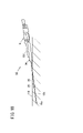
- FIG. 1 is a perspective view of an implantable body indwelling device according to an embodiment in a separated state;
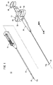
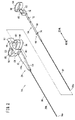
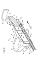
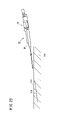
- FIG. 2 is a perspective view showing components of the operating device of FIG. 1;
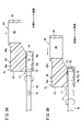
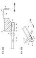
- FIG. 3A is an enlarged perspective view of the distal end portion of the outer cylinder shown in FIG. 2, and
- FIG. 3B is a side view of the distal end portion of FIG. 3A.
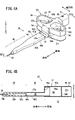
- 4A is a perspective view of the barrel hub of FIG. 2, and FIG. 4B is a cross-sectional view of the barrel hub taken along line IVB-IVB of FIG. 4A.
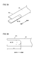
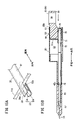
- 5A is an enlarged perspective view of the distal end of the shaft of FIG. 2, and
- FIG. 5B is a side view of the distal end of FIG. 5A.
- FIG. 3 is a perspective view of the shaft hub of FIG. 2;
- FIG. FIG. 4 is an enlarged cross-sectional view of the vicinity of the operating portion of the shaft hub in the released state;
- FIG. 3 is an exploded perspective view showing a rotation mechanism of the shaft hub of FIG. 2;
- 9A is a cross-sectional view of the operating portion of the shaft hub pulled out from the rotating shaft portion, and
- FIG. 9B is a cross-sectional view of the operating portion of the shaft hub pushed into the rotating shaft portion.
- FIG. 2 is a perspective cross-sectional view of a barrel hub and a shaft hub of the operating device of FIG. 1;
- FIG. 2 is a cutaway perspective view showing the internal structure by cutting out a portion of the outer cylinder hub of FIG. 1 ;
- FIG. 2 is a cross-sectional view showing the upper portion of the outer cylinder hub of FIG. 1 with a cutout;
- FIG. 2 is a perspective view showing parts constituting the puncture needle of FIG. 1;
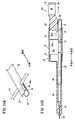
- 14A is a perspective view of the outer cylinder and shaft in the released state, and
- FIG. 14B is a cross-sectional view showing the movement of the shaft hub in the released state of FIG. 14A.
- 15A is a perspective view of the outer cylinder and shaft in a fixed state, and FIG. 15B is a cross-sectional view showing the operation of the shaft hub in the fixed state of FIG. 15A.
- FIG. 4 is an explanatory diagram showing a state in which the skin of a living body is punctured with a puncture needle;
- FIG. 4 is an explanatory diagram showing a state in which the skin of a living body is punctured with a puncture needle;
- FIG. 4 is an explanatory diagram showing a state in which the skin of a living body is
- FIG. 10 is an explanatory view showing an operation after pulling out the inner needle assembly from the puncture needle; It is explanatory drawing which shows operation which inserts an operation device in an outer needle assembly.
- 19A is a top view showing the operation of pressing the outer cylinder hub of the operation device against the skin
- FIG. 19B is a side view of FIG. 19A.
- 20A is a top view showing the positional relationship between the lock protrusion and the outer needle hub
- FIG. 20B is a side view of FIG. 20A.
- 21A is a top view showing the positional relationship between the lock protrusion and the outer needle hub when the tip of the operating device is projected from the outer needle
- FIG. 21B is a side view of FIG. 21A.
- FIG. 21A is a top view showing the positional relationship between the lock protrusion and the outer needle hub when the tip of the operating device is projected from the outer needle
- FIG. 21B is a side view of FIG. 21A.
- FIG. 22A is a cross-sectional view showing the operation of putting the operating device into the released state
- FIG. 22B is a perspective view showing the released state of the outer cylinder and the shaft of the operating device.
- FIG. 10 is an explanatory view showing the operation of withdrawing the outer needle assembly and the operating device from the skin leaving the implant.
- the hand side when handled by the user is called the “base end side”
- the needle tip side away from the user is called the “distal end side”.
- the implantable body retention device 10 includes a puncture needle 12 and an operation device 14, as shown in FIG.
- the puncture needle 12 has an outer needle 16 and an inner needle 18, and a sharp needle tip is formed at the tip 18a of the inner needle 18. 18 is used by puncturing the target site inside the living tissue 116 .
- the operating device 14 is used by being inserted inside the outer needle 16 after puncturing the target site with the puncture needle 12 .
- the operation device 14 has a grasping mechanism 22 that holds a fibrous implant 110 (see FIG. 17, etc.) at the tip 14a, and puncture is performed while the implant 110 (see FIG. 14A) is held at the tip 14a. It is inserted into the outer needle 16 of the needle 12 to deliver the implant 110 to the target site.
- the operating device 14 includes an outer cylinder assembly 24 and a shaft assembly 26.
- the operation device 14 is assembled by arranging the shaft assembly 26 inside the barrel assembly 24 .
- the outer tube assembly 24 includes an elongated outer tube 28 and an outer tube hub 30 joined to the base end side of the outer tube 28 .
- the outer cylinder 28 is a cylindrical member made of metal such as stainless steel, hard resin, or the like, and is formed with a bore 28b extending therethrough in the axial direction.
- the outer cylinder 28 has a diameter that allows it to be inserted into the outer needle 16 of the puncture needle 12 shown in FIG.
- a lumen 28 b of the outer cylinder 28 is open on the proximal side and communicates with a cavity 30 a of the outer cylinder hub 30 .
- an end face 32 substantially perpendicular to the axial direction of the outer cylinder 28 is formed at the tip 28a of the outer cylinder 28.
- a pair of first insertion holes 34 that constitute a part of the gripping mechanism 22 are formed in an outer peripheral portion closer to the base end than the end surface 32 .
- the first insertion holes 34 are arranged at positions facing each other with the central axis of the outer cylinder 28 interposed therebetween.
- the first insertion hole 34 holds the embedded body 110 so as to pass through the outer cylinder 28 in the radial direction.
- the circumferential dimension A of the first insertion hole 34 is larger than the diameter of the embedded body 110 . Further, the first insertion hole 34 extends long in the axial direction, and the dimension B in the axial direction is larger than the dimension A in the circumferential direction.
- the first insertion hole 34 is open at the end surface 32 and formed in a groove shape. Although the first insertion hole 34 does not have to open on the end face 32, it is preferable to open it on the end face 32 because it facilitates the work of disposing the thin embedding body 110. As shown in FIG.
- the outer tube hub 30 is joined to the proximal end of the outer tube 28 .
- the outer tube hub 30 is made of, for example, a hard resin material such as polycarbonate resin.
- a connecting portion 38 for holding the outer cylinder 28 is provided on the distal end side of the outer cylinder hub 30 .
- the connecting portion 38 is a portion tapered toward the distal end side, and the inside thereof is tightly joined to the outer peripheral portion of the outer cylinder 28 .
- a rectangular tubular portion 40 having a rectangular cross section is formed on the proximal end side of the connecting portion 38 .
- the square tubular portion 40 is a tubular portion having a rectangular cross section perpendicular to the axial direction, elongated in the axial direction, and thin in the vertical direction.
- the rectangular tubular portion 40 has a flat upper surface 40a at its upper end, side surfaces 40b and 40c on both sides, and a flat bottom surface 40d at its lower end.
- a first scale line 42a and a second scale line 42b are formed as grooves extending in the width direction near the base end of the upper surface 40a.
- Lock projections 44 are formed on the side surfaces 40b and 40c.
- a first hollow portion 46 is formed inside the square tubular portion 40 .
- the first hollow portion 46 is formed to extend in the axial direction of the rectangular tubular portion 40 .
- a thick portion 38 a of the connecting portion 38 is formed on the tip side of the first cavity portion 46 .
- a shaft hole 38b is formed through the thick portion 38a in the axial direction.
- the outer cylinder 28 is inserted into and joined to the tip of the shaft hole 38b, and the tip of the shaft hole 38b communicates with the inner cavity 28b of the outer cylinder 28.
- a distal end wall 46b is formed as a wall portion at the distal end of the first hollow portion 46 (base end of the thick portion 38a).
- the shaft hole 38b opens at the tip wall 46b and communicates with the first hollow portion 46 .
- a rotating shaft portion 68 (described later) of the shaft assembly 26 is rotatably accommodated in the shaft hole 38b and the first hollow portion 46 .
- a joint portion 50a for attaching a molded body 50b is formed at the proximal end of the rectangular tubular portion 40.
- the joint portion 50 a is formed in the shape of a wall that rises upward from the base end of the rectangular tubular portion 40 .
- the joint portion 50 a constitutes a portion of the grip portion 50 on the distal end side.
- the gripping portion 50 is provided on the proximal end side of the rectangular tubular portion 40 .
- the grip portion 50 is composed of a joint portion 50a and a formed body 50b connected to the proximal end side of the joint portion 50a.
- the molded body 50b is made of the same resin material as the rectangular tubular portion 40, and is joined to the base end side of the joint portion 50a by a method such as adhesion, welding, or caulking.
- the gripping portion 50 includes a main body portion 53, a pair of support plates 54, a pair of gripping rings 56, and a housing portion 61.
- the body portion 53 is a tubular member formed in a box shape, and is formed to be larger than the rectangular tube portion 40 in the vertical direction.
- a second cavity portion 58 and a base end wall 58a are formed inside the body portion 53.
- the tip end side of the second hollow portion 58 communicates with the first hollow portion 46 of the rectangular tubular portion 40 .
- the proximal end wall 58 a is provided on the proximal end side of the second hollow portion 58 .
- the proximal wall 58 a is provided on the proximal side of the second cavity 58 and partitions the proximal side of the second cavity 58 .
- the base end wall 58a is formed with a shaft hole 58b through which the rotation shaft portion 68 (see FIG. 2) is inserted.
- the housing portion 61 is formed on the base end side of the body portion 53.
- the housing portion 61 is a tubular portion formed in an oval shape (non-circular shape) that is elongated in the vertical direction.
- a housing hole 61a is formed inside the housing portion 61.
- the accommodation hole 61a extends in the axial direction and opens to the base end side.
- the accommodation hole 61a accommodates an operating portion 70 (described later) of the shaft assembly 26 so as to be slidable in the axial direction.
- An engaging hole 59 is formed in the upper end portion of the accommodating portion 61 .
- the engaging hole 59 penetrates the upper end wall of the housing portion 61 and communicates with the housing hole 61a.
- the support plate 54 is a plate-shaped member extending in the width direction from the lower end of the main body portion 53. As shown in FIG. The support plate 54 is formed in a trapezoidal shape in plan view, and is provided in pairs on one side portion 52 a and the other side portion 52 b of the main body portion 53 . The support plate 54 is formed in a flat plate shape parallel to the bottom surface 40 d of the rectangular tubular portion 40 .
- the grip ring 56 is a tubular member extending in the width direction from the vicinity of the upper end of the body portion 53 .
- a pair of gripping rings 56 are provided on one side portion 52 a and the other side portion 52 b of the body portion 53 .
- the grip ring 56 is formed in a trapezoidal shape in a plan view, and a finger hooking hole 60 is formed vertically through the inside thereof.
- the shape of the outer peripheral portion of the grip ring 56 when viewed from above is the same as that of the support plate 54 .
- the finger hook hole 60 of the grip ring 56 is formed in a trapezoidal shape whose axial dimension narrows outward in the width direction.
- shaft assembly 26 includes shaft 62 and shaft hub 64 joined to the proximal end of shaft 62 .
- the shaft 62 is formed in a cylindrical shape with an outer diameter that can be inserted into the lumen 28 b of the outer cylinder 28 .
- the shaft 62 is made of metal such as stainless steel.
- the shaft 62 is not limited to a cylindrical shape, and may be hollow cylindrical.
- a second insertion hole 66 is formed in the distal end portion 62a of the shaft 62.
- the second insertion hole 66 is formed so as to penetrate the side portion of the shaft 62 in the radial direction.
- the second insertion hole 66 extends long in the axial direction, opens at the tip of the shaft 62, and is formed as a U-shaped notch groove when viewed from the side.
- the second insertion hole 66 is formed in a portion (corresponding portion) of the shaft 62 inside the first insertion hole 34 .
- the width (circumferential dimension C) of the second insertion hole 66 is larger than the diameter of the implant 110 .
- the length (dimension D in the axial direction) of the second insertion hole 66 is formed larger than the width.
- a shaft hub 64 is provided at the proximal end of the shaft 62 .
- the shaft hub 64 is joined to the shaft 62 and includes a cylindrical rotation shaft portion 68 elongated in the axial direction, and an operation portion 70 provided on the base end side of the rotation shaft portion 68 .
- the rotating shaft portion 68 is a member made of a resin material such as polycarbonate resin, and is joined to the base end portion of the shaft 62 .
- the rotating shaft portion 68 is joined to rotate integrally with the shaft 62 .
- a first blade portion 72 and a second blade portion 74 are formed on the outer peripheral portion of the rotating shaft portion 68 so as to protrude radially outward.
- the first blade portion 72 is a protrusion provided near the proximal end of the rotating shaft portion 68 .
- the first blade portion 72 is composed of a pair of blade-like projections 72a that face each other with the center of the rotation shaft portion 68 interposed therebetween.
- the second blade portion 74 is a projection provided near the tip of the rotating shaft portion 68, and is composed of a pair of blade-shaped projections 74a arranged at positions facing each other.
- a sliding portion 76 protruding radially outward is provided at the proximal end of the rotating shaft portion 68 .
- the sliding portion 76 is formed with a constant protrusion height over the entire circumference of the rotating shaft portion 68 .
- an outer peripheral surface 76a of the sliding portion 76 slides in contact with a rotation shaft accommodating hole 78 of the operating portion 70, which will be described later.
- a thread groove 76b is formed by notching the sliding portion 76 in a part of the sliding portion 76 in the circumferential direction.
- the screw groove 76b is formed slightly inclined with respect to the axial direction.
- a pair of screw grooves 76 b are provided at positions facing each other in the circumferential direction of the rotation shaft portion 68 .
- the operating portion 70 has a shaft accommodating portion 80 in which a rotating shaft portion accommodating hole 78 is formed.
- the shaft receiving portion 80 is formed in a cylindrical shape coaxial with the central axis of the rotation shaft portion receiving hole 78 .
- a connecting portion 82 is formed in an upper portion of the shaft accommodating portion 80 so as to be integrally connected with the shaft accommodating portion 80 .
- the upper end of the connecting portion 82 is formed in a cylindrical shape.
- the shaft receiving portion 80 and the connecting portion 82 of the operating portion 70 slide along the receiving hole 61 a (see FIG. 4B ) of the outer cylinder hub 30 .
- the upper end of the connecting portion 82 is formed with a distal scale line 85a, a proximal scale line 85b and an engaging projection 88.
- the distal graduation line 85a and the proximal graduation line 85b are groove-like structures extending in the width direction, and are spaced apart in the axial direction.
- the distal scale line 85a is a line indicating that the gripping mechanism 22 is in the released state, and is provided at a position that coincides with the proximal end of the main body portion 53 when the operation portion 70 is pulled out to the proximal end side.
- the engaging protrusion 88 is provided between the distal scale line 85a and the proximal scale line 85b.
- the engagement protrusion 88 is provided at a position where it engages with the engagement hole 59 when the operation portion 70 is pushed in, and maintains the gripping mechanism 22 in the released state.
- the base end scale line 85b is provided at a portion that coincides with the base end of the housing portion 61 when the engagement protrusion 88 is engaged with the engagement hole 59. As shown in FIG.
- An operation ring 84 is formed at the proximal end of the connecting portion 82 .
- the operation ring 84 is oval in plan view.
- a finger hooking hole 86 is formed through the operation ring 84 in the vertical direction.
- the finger hooking hole 86 is a portion where the thumb of the user is hooked, and is formed to have a larger diameter than the finger hooking hole 60 of the outer tube hub 30 . Since the finger hooking hole 86 is formed in an elliptical shape, the user can hook the finger without any gap in the axial direction by adjusting the finger in the width direction according to the size of the finger.
- the rotation shaft receiving hole 78 inside the shaft receiving portion 80 is formed to extend in the axial direction.
- the rotation shaft housing hole 78 accommodates the sliding portion 76 at the proximal end of the rotation shaft 68 so as to be slidable in the axial direction.
- a pair of screw threads 78b are provided on the inner peripheral surface 78a of the rotation shaft housing hole 78 so as to protrude inward.
- the thread 78b is provided at a portion that engages with the thread groove 76b, and extends while rotating in the axial direction.
- the turning mechanism 77 of this embodiment is configured by a screw structure having the screw thread 78b and the screw groove 76b.
- FIG. 9A when the user pulls out the operation portion 70 from the rotation shaft portion 68, a counterclockwise rotational movement is produced when viewed from the base end side (user side).
- FIG. 9B when the user performs an operation of pushing the operating portion 70 toward the rotating shaft portion 68, a clockwise rotational motion is produced when viewed from the base end side.
- the direction of rotation is not limited to the above example, and may be reversed.
- the shaft hub 64 is mounted inside the outer tube hub 30 .
- the rotating shaft portion 68 of the shaft hub 64 passes through the shaft hole 58b of FIG. 4B and is accommodated in the shaft hole 38b of the outer cylinder hub 30, the first cavity portion 46, and the second cavity portion 58.
- the operation portion 70 of the shaft hub 64 is accommodated in the accommodation portion 61 of the grip portion 50 of the outer cylinder hub 30 so as to be slidable in the axial direction. Since the operation portion 70 and the accommodation hole 61a of the accommodation portion 61 are formed in a non-circular shape, the operation portion 70 is axially displaced without rotating.
- the rotating shaft portion 68 is housed rotatably with respect to the outer tube hub 30 .
- a pair of rotation restricting projections 92 as rotation restricting portions 90 are formed on the base end wall 58 a of the outer tube hub 30 .
- the pair of rotation restricting projections 92 are provided with a predetermined angle in the circumferential direction of the rotation shaft portion 68 , and the first blade portion 72 is arranged between the pair of rotation restricting projections 92 .
- the rotation restricting protrusion 92 abuts on the first blade portion 72 to restrict the rotation angle range of the rotating shaft portion 68 to the range of the released state and the range of the fixed state.
- the rotation restricting portion 90 includes a first blade portion 72 and a rotation restricting protrusion 92 . Note that the first blade portion 72 prevents the rotation shaft portion 68 from moving to the proximal end side by coming into contact with the proximal end wall 58a.
- the second blade portion 74 abuts on the distal end wall 46b of the outer tube hub 30 from the proximal side to prevent the rotation shaft portion 68 from moving to the distal side. That is, the distal end wall 46b, the proximal end wall 58a, the first blade portion 72, and the second blade portion 74 prevent axial displacement of the rotary shaft portion 68 with respect to the outer tube hub 30. As shown in FIG. 12, the distal end wall 46b, the proximal end wall 58a, the first blade portion 72, and the second blade portion 74 prevent axial displacement of the rotary shaft portion 68 with respect to the outer tube hub 30. As shown in FIG.
- the puncture needle 12 includes an outer needle assembly 94 and an inner needle assembly 96.
- the inner needle assembly 96 is detachably attached to the outer needle assembly 94 from the base end side of the outer needle assembly 94 .
- the outer needle assembly 94 has a cylindrical outer needle 16 with a blunt tip 16 a and an outer needle hub 100 provided at the proximal end of the outer needle 16 .
- An axially extending lumen 16b is formed through the interior of the outer needle 16 .
- a hollow portion 100a is formed in the outer needle hub 100 .
- the hollow portion 100a opens at a guide groove 100b at the upper end. Engagement holes 100c are formed on both sides of the outer needle hub 100 on the proximal end side.
- the inner needle assembly 96 includes an inner needle 18 having a sharp distal end 18a and an inner needle hub 104 provided on the proximal end side of the inner needle 18.
- Inner needle 18 is axially slidably disposed within lumen 16b of outer needle 16 .
- the inner needle assembly 96 can be withdrawn from the proximal side of the outer needle assembly 94 .
- the puncture needle 12 is used by attaching the inner needle assembly 96 to the outer needle assembly 94 and piercing from the skin 112 of the patient (living body) to the target site in the living tissue.
- the implantable body retention device 10 and the operation device 14 of this embodiment are configured as described above, and the operation thereof will be described below together with the method of use.
- the operation of attaching the implant 110 to the operation device 14 will be described.
- the user grips the operating device 14 by inserting the index finger and the middle finger into the finger hooking holes 60 of the outer tube hub 30 of the operating device 14 shown in FIG. 14B, the operating device 14 in the initial state has the operating portion 70 of the shaft hub 64 pulled out to the proximal side, and the engaging projection 88 is located on the proximal side of the outer cylinder hub 30.
- the tip scale line 85 a overlaps the base end of the housing portion 61 of the outer cylinder hub 30 . In this state, as shown in FIG.
- the released state is achieved in which the second insertion hole 66 of the shaft 62 and the first insertion hole 34 of the outer cylinder 28 are aligned in the circumferential direction.
- the user can visually recognize the open state from the position of the tip scale line 85a shown in FIG.
- the user holds the thread-like embedding body 110 with tweezers or the like, and arranges the embedding body 110 so that it passes through the first insertion hole 34 and the second insertion hole 66. .
- the user pushes the operating portion 70 toward the outer cylinder hub 30. Then, as shown in FIG. By this operation, the engaging protrusion 88 of the operating portion 70 engages with the engaging hole 59 of the outer cylinder hub 30 and stops.
- the sliding portion 76 of the rotating shaft portion 68 slides in the inside of the rotating shaft portion accommodating hole 78 in the axial direction. Axial displacement of the operating portion 70 is converted into rotational displacement of the rotating shaft portion 68 (see FIG. 7) by the screw groove 76b and the screw thread 78b that constitute the rotating mechanism 77 shown in FIG.
- the driving shaft portion 68 rotates.
- the implant 110 is in an unremovable fixed state.
- the operating device 14 is maintained in a fixed state by engaging the engaging projections 88 of the operating portion 70 with the engaging holes 59 of the outer tube hub 30 . In this state, the base end graduation line 85b and the position of the base end of the accommodating portion 61 match. The above operation completes the attachment of the implant 110 to the operation device 14 .
- the user punctures the target site of the patient (living body) with the puncture needle 12 .
- the user pulls out the inner needle assembly 96 from the outer needle assembly 94 while leaving the outer needle assembly 94 of the puncture needle 12 .
- the user inserts the operation device 14 holding the implant 110 from the proximal end of the outer needle hub 100 of the outer needle assembly 94. Then, the user inserts the outer tube 28 of the operating device 14 into the lumen 16b of the outer needle 16 of the outer needle assembly 94, and moves the implant 110 into the body of the living body through the interior of the lumen 16b. Since the implant 110 is protected by the outer needle 16, it is not subjected to drag when it advances in the living body. As a result, even if the target site is deep in the living tissue 116, the implant 110 can be delivered without breaking. As shown in FIGS.
- the user performs an operation to project the grasping mechanism 22 of the operation device 14 beyond the tip 16 a of the outer needle 16 .
- the operation device 14 is fixed to the biological tissue 116, and the outer needle assembly 94 is positioned proximally. move to That is, as shown in FIGS. 19A and 19B , the user presses the grip portion 50 of the outer tube hub 30 toward the skin 112 with fingers to fix the operation device 14 to the living tissue 116 .
- the support plate 54 of the grip portion 50 is in surface contact with the skin 112, and the grip portion 50 is securely fixed in a stable state.
- the user holds the outer needle hub 100 and slides the outer needle hub 100 toward the outer cylinder hub 30 toward the proximal end side.
- the locking projection 44 engages with the engaging hole 100c of the outer needle hub 100.
- the lock protrusion 44 fixes the grasping mechanism 22 of the operation device 14 while protruding from the distal end 16 a of the outer needle 16 .
- the second scale line 42b coincides with the proximal end of the outer needle hub 100, so the user can visually recognize the protrusion of the gripping mechanism 22 at the position of the second scale line 42b.
- the user pulls out the operation section 70 to the proximal end side as shown in FIG. 22A in order to switch the fixed state of the gripping mechanism 22 of the operation device 14 to the released state.
- the shaft 62 rotates together with the rotating shaft portion 68, and as shown in FIG. coincide with each other in the circumferential direction.
- the grasping mechanism 22 of the operation device 14 is in a released state in which the implant 110 can be detached.
- the grasping mechanism 22 of the operation device 14 of this embodiment can switch between the fixed state and the released state only by rotating the shaft 62 inside the outer cylinder 28 without protruding outward from the outer cylinder 28 . Therefore, even when the pressure inside the living tissue 116 acts on the grasping mechanism 22 of the present embodiment, the release operation is less likely to be hindered. can be released with certainty.
- the user pulls out the operating device 14 together with the outer needle assembly 94 from the skin 112 of the living body, as shown in FIG.
- the implant 110 is separated from the grasping mechanism 22 by friction with the living tissue 116 and left in the living tissue 116 .
- the operation device 14 and the implantable body retention device 10 of this embodiment have the following effects.
- the operating device 14 of the present embodiment includes an outer cylinder 28 having a bore 28b extending therethrough in the axial direction, a shaft 62 arranged in the bore 28b, and a filament-like body provided on the outer cylinder 28 and the shaft 62.
- a gripping mechanism 22 for gripping the implant 110 so as to be switchable between a fixed state that cannot be detached and a released state that can be detached.
- a second insertion hole 66 is provided in the shaft 62 at a portion corresponding to the first insertion hole 34 and the first insertion hole 34 , and radially penetrates the side portion of the shaft 62 . and a rotation mechanism 77 for rotating, and inserts the implant 110 through the first insertion hole 34 and the second insertion hole 66 and grips it.
- the implant 110 can be released simply by rotating the shaft 62 inside the outer cylinder 28 without protruding outside the outer cylinder 28 . Therefore, the implant 110 can be reliably released even inside the living tissue 116 where pressure is applied, so that the implant 110 can be reliably left inside the living tissue 116 .
- the first through-hole 34 and the second through-hole 66 may be formed in a groove shape with an opening at the tip.
- the side portion of the implant 110 can be arranged in the first insertion hole 34 and the second insertion hole 66 by sliding the side portion of the implant 110 from the distal end side to the proximal end side. There is no need to pass the tip of the fragile implant 110 through the first insertion hole 34 and the second insertion hole 66, and the attachment of the implant 110 is facilitated.
- the circumferential dimension of the first insertion hole 34 and the second insertion hole 66 is larger than the diameter of the embedded body 110
- the axial dimension of the first insertion hole 34 and the second insertion hole 66 is larger than the diameter of the embedded body 110.
- the dimension may be larger than the circumferential dimension.
- the positions of the first insertion hole 34 and the second insertion hole 66 are displaced in the circumferential direction, and the embedded body 110 is sandwiched between the shaft 62 and the outer cylinder 28 .
- the implant 110 can be securely fixed in the grasping mechanism 22 .
- the implant 110 in the released state, the circumferential positions of the first insertion hole 34 and the second insertion hole 66 match. According to this configuration, the implant 110 can be released without performing the operation of protruding the outer cylinder 28 to the outside, so that the release operation can be reliably performed even inside the living tissue 116 .
- the operation device 14 further includes an outer cylinder hub 30 joined to the proximal end of the outer cylinder 28 and a shaft 62 that supports the proximal end of the shaft 62 and is axially movable with respect to the outer cylinder hub 30 .
- a shaft hub 64 attached thereto, the shaft hub 64 being joined to the proximal end of the shaft 62 and rotating integrally with the shaft 62; and an operating portion 70 having a rotation shaft accommodation hole 78 slidably accommodated in the rotation mechanism 77 .
- the rotation mechanism 77 is formed by the inner wall of the rotation shaft accommodation hole 78 and the outer circumference of the rotation shaft 68
- a screw mechanism that converts axial displacement of the operating portion 70 into rotational displacement of the rotating shaft portion 68 may be provided.
- the shaft hub 64 by operating the shaft hub 64, the shaft 62 can be rotationally displaced, resulting in excellent operability.
- the operation device 14 described above may further include a rotation restricting portion 90 that restricts the rotation range of the rotating shaft portion 68 .
- the rotation range of the rotation shaft portion 68 can be set between the released state and the fixed state, and even when the grasping mechanism 22 is inserted into the living body and cannot be visually recognized, the movement can be reliably performed. operation becomes possible.
- the rotation restricting portion 90 may have a rotation restricting protrusion 92 provided on the outer tube hub 30 and the first blade portion 72 projecting outward from the rotating shaft portion 68. good. According to this configuration, the rotation can be restricted with a simple device configuration.
- the rotating shaft portion 68 has a second blade portion 74 protruding outward, and the outer tube hub 30 abuts on the second blade portion 74 in the axial direction to rotate the rotating shaft portion 68 .
- a wall portion (tip wall 46 b ) that prevents axial displacement with respect to the outer cylinder hub 30 may be provided.
- the implant placement device 10 of this embodiment includes the operation device 14 described above, a puncture needle 12 having an outer needle 16 that can be inserted into the outer cylinder 28 of the operation device 14 while gripping the implant 110, Prepare. According to this implant placement device 10 , the implant 110 can be reliably placed inside the living tissue 116 .
Landscapes
- Health & Medical Sciences (AREA)
- Surgery (AREA)
- Life Sciences & Earth Sciences (AREA)
- Medical Informatics (AREA)
- Animal Behavior & Ethology (AREA)
- Engineering & Computer Science (AREA)
- Biomedical Technology (AREA)
- Heart & Thoracic Surgery (AREA)
- Veterinary Medicine (AREA)
- Molecular Biology (AREA)
- Nuclear Medicine, Radiotherapy & Molecular Imaging (AREA)
- General Health & Medical Sciences (AREA)
- Public Health (AREA)
- Pathology (AREA)
- Infusion, Injection, And Reservoir Apparatuses (AREA)
- Media Introduction/Drainage Providing Device (AREA)
- Surgical Instruments (AREA)
Abstract
Priority Applications (3)
| Application Number | Priority Date | Filing Date | Title |
|---|---|---|---|
| EP22742528.7A EP4272657B1 (fr) | 2021-01-19 | 2022-01-17 | Dispositif d'actionnement et outil d'implant à demeure |
| JP2022576662A JP7726925B2 (ja) | 2021-01-19 | 2022-01-17 | 操作デバイス及び埋込体留置具 |
| US18/349,255 US20230346413A1 (en) | 2021-01-19 | 2023-07-10 | Operation device and implanted body indwelling instrument |
Applications Claiming Priority (2)
| Application Number | Priority Date | Filing Date | Title |
|---|---|---|---|
| JP2021-006142 | 2021-01-19 | ||
| JP2021006142 | 2021-01-19 |
Related Child Applications (1)
| Application Number | Title | Priority Date | Filing Date |
|---|---|---|---|
| US18/349,255 Continuation US20230346413A1 (en) | 2021-01-19 | 2023-07-10 | Operation device and implanted body indwelling instrument |
Publications (1)
| Publication Number | Publication Date |
|---|---|
| WO2022158406A1 true WO2022158406A1 (fr) | 2022-07-28 |
Family
ID=82548992
Family Applications (1)
| Application Number | Title | Priority Date | Filing Date |
|---|---|---|---|
| PCT/JP2022/001261 Ceased WO2022158406A1 (fr) | 2021-01-19 | 2022-01-17 | Dispositif d'actionnement et outil d'implant à demeure |
Country Status (4)
| Country | Link |
|---|---|
| US (1) | US20230346413A1 (fr) |
| EP (1) | EP4272657B1 (fr) |
| JP (1) | JP7726925B2 (fr) |
| WO (1) | WO2022158406A1 (fr) |
Cited By (3)
| Publication number | Priority date | Publication date | Assignee | Title |
|---|---|---|---|---|
| WO2024225199A1 (fr) * | 2023-04-25 | 2024-10-31 | テルモ株式会社 | Dispositif d'actionnement et instrument implanté à demeure |
| WO2025070273A1 (fr) * | 2023-09-25 | 2025-04-03 | テルモ株式会社 | Dispositif pour installation à demeure d'un corps intégré |
| WO2025204597A1 (fr) * | 2024-03-25 | 2025-10-02 | テルモ株式会社 | Dispositif de déploiement de corps implanté |
Citations (7)
| Publication number | Priority date | Publication date | Assignee | Title |
|---|---|---|---|---|
| US9301748B2 (en) | 2013-07-16 | 2016-04-05 | Suture Ease, Inc. | Suture apparatus, system and method |
| JP2016513575A (ja) * | 2013-03-15 | 2016-05-16 | アルファ サイエンティフィック コーポレイションAlpha Scientific Corporation | 横係合を備える外科用縫合装置 |
| WO2017163600A1 (fr) * | 2016-03-25 | 2017-09-28 | 株式会社カネカ | Dispositif de suture médicale bidirectionnelle et son procédé de fonctionnement |
| WO2020039314A2 (fr) * | 2018-08-20 | 2020-02-27 | Ethicon Llc | Instruments chirurgicaux motorisés à agencements d'embrayage pour convertir des mouvements d'entraînement linéaires en mouvements d'entraînement rotatifs |
| JP2020525160A (ja) * | 2017-06-29 | 2020-08-27 | エシコン エルエルシーEthicon LLC | 縫合糸把持具 |
| JP2020127607A (ja) | 2019-02-08 | 2020-08-27 | テルモ株式会社 | 埋込体留置具及び埋込体 |
| WO2020189157A1 (fr) * | 2019-03-18 | 2020-09-24 | テルモ株式会社 | Instrument de mise en place d'implant |
Family Cites Families (3)
| Publication number | Priority date | Publication date | Assignee | Title |
|---|---|---|---|---|
| CA2829882C (fr) * | 2011-03-23 | 2020-03-31 | Jeffrey E. Yeung | Soulagement des douleurs dorsales et reparation des disques intervertebraux a travers une aiguille |
| EP2825101A4 (fr) * | 2012-03-13 | 2015-12-16 | Suture Ease Llc | Aiguille et appareil de guidage pour boucle en forme d'anse, pour le passage de fil de suture |
| US10582925B2 (en) * | 2017-02-06 | 2020-03-10 | Medos International Sarl | Devices, systems, and methods for knotless suture anchors |
-
2022
- 2022-01-17 JP JP2022576662A patent/JP7726925B2/ja active Active
- 2022-01-17 WO PCT/JP2022/001261 patent/WO2022158406A1/fr not_active Ceased
- 2022-01-17 EP EP22742528.7A patent/EP4272657B1/fr active Active
-
2023
- 2023-07-10 US US18/349,255 patent/US20230346413A1/en active Pending
Patent Citations (7)
| Publication number | Priority date | Publication date | Assignee | Title |
|---|---|---|---|---|
| JP2016513575A (ja) * | 2013-03-15 | 2016-05-16 | アルファ サイエンティフィック コーポレイションAlpha Scientific Corporation | 横係合を備える外科用縫合装置 |
| US9301748B2 (en) | 2013-07-16 | 2016-04-05 | Suture Ease, Inc. | Suture apparatus, system and method |
| WO2017163600A1 (fr) * | 2016-03-25 | 2017-09-28 | 株式会社カネカ | Dispositif de suture médicale bidirectionnelle et son procédé de fonctionnement |
| JP2020525160A (ja) * | 2017-06-29 | 2020-08-27 | エシコン エルエルシーEthicon LLC | 縫合糸把持具 |
| WO2020039314A2 (fr) * | 2018-08-20 | 2020-02-27 | Ethicon Llc | Instruments chirurgicaux motorisés à agencements d'embrayage pour convertir des mouvements d'entraînement linéaires en mouvements d'entraînement rotatifs |
| JP2020127607A (ja) | 2019-02-08 | 2020-08-27 | テルモ株式会社 | 埋込体留置具及び埋込体 |
| WO2020189157A1 (fr) * | 2019-03-18 | 2020-09-24 | テルモ株式会社 | Instrument de mise en place d'implant |
Cited By (3)
| Publication number | Priority date | Publication date | Assignee | Title |
|---|---|---|---|---|
| WO2024225199A1 (fr) * | 2023-04-25 | 2024-10-31 | テルモ株式会社 | Dispositif d'actionnement et instrument implanté à demeure |
| WO2025070273A1 (fr) * | 2023-09-25 | 2025-04-03 | テルモ株式会社 | Dispositif pour installation à demeure d'un corps intégré |
| WO2025204597A1 (fr) * | 2024-03-25 | 2025-10-02 | テルモ株式会社 | Dispositif de déploiement de corps implanté |
Also Published As
| Publication number | Publication date |
|---|---|
| EP4272657B1 (fr) | 2026-01-28 |
| JPWO2022158406A1 (fr) | 2022-07-28 |
| US20230346413A1 (en) | 2023-11-02 |
| JP7726925B2 (ja) | 2025-08-20 |
| EP4272657A4 (fr) | 2024-05-29 |
| EP4272657A1 (fr) | 2023-11-08 |
Similar Documents
| Publication | Publication Date | Title |
|---|---|---|
| US12349877B2 (en) | Assistive device for removing a biological sample from an intraosseous device, and related kits and methods | |
| WO2022158406A1 (fr) | Dispositif d'actionnement et outil d'implant à demeure | |
| US5817110A (en) | Abdominal incision suturing apparatus | |
| US8409232B2 (en) | Surgical instrument assembly | |
| US9918712B2 (en) | Devices, systems, and methods for providing surgical access and facilitating closure of surgical access openings | |
| US6159224A (en) | Multiple needle suturing instrument and method | |
| EP3569156A2 (fr) | Ensembles et kits d'aiguilles intraosseuses | |
| US9125637B2 (en) | Method of loading a locked tissue biopsy needle into a biopsy gun | |
| JP2006341095A (ja) | 着脱可能な深さ止めを有する針アッセンブリ | |
| AU2017204794A1 (en) | Intraosseous device handles, systems, and methods | |
| WO2000059378A2 (fr) | Aiguille a ponction-biopsie et instrument chirurgical | |
| WO2009068661A1 (fr) | Dispositif pour thoracotomie | |
| US9693769B2 (en) | Suture device | |
| EP3607867A1 (fr) | Dispositif de recharge d'aiguille à utiliser avec un dispositif endostitch | |
| JP6737870B2 (ja) | 医療用双方向縫合装置およびその作動方法 | |
| JPWO2018037952A1 (ja) | 医療用双方向縫合装置およびその作動方法 | |
| CN117503209A (zh) | 组织活检装置 | |
| US20210361405A1 (en) | Implant insertion device and implant | |
| CN115153687A (zh) | 腔内手术器械 | |
| JP7541935B2 (ja) | 操作デバイス及び埋込体留置具 | |
| KR102580423B1 (ko) | 성형용 리프팅 부재 |
Legal Events
| Date | Code | Title | Description |
|---|---|---|---|
| 121 | Ep: the epo has been informed by wipo that ep was designated in this application |
Ref document number: 22742528 Country of ref document: EP Kind code of ref document: A1 |
|
| ENP | Entry into the national phase |
Ref document number: 2022576662 Country of ref document: JP Kind code of ref document: A |
|
| ENP | Entry into the national phase |
Ref document number: 2022742528 Country of ref document: EP Effective date: 20230731 |
|
| NENP | Non-entry into the national phase |
Ref country code: DE |
|
| WWG | Wipo information: grant in national office |
Ref document number: 2022742528 Country of ref document: EP |