WO2022158552A1 - Dispositif de stockage d'énergie - Google Patents
Dispositif de stockage d'énergie Download PDFInfo
- Publication number
- WO2022158552A1 WO2022158552A1 PCT/JP2022/002105 JP2022002105W WO2022158552A1 WO 2022158552 A1 WO2022158552 A1 WO 2022158552A1 JP 2022002105 W JP2022002105 W JP 2022002105W WO 2022158552 A1 WO2022158552 A1 WO 2022158552A1
- Authority
- WO
- WIPO (PCT)
- Prior art keywords
- power storage
- gas
- diffusion member
- gas diffusion
- storage elements
- Prior art date
- Legal status (The legal status is an assumption and is not a legal conclusion. Google has not performed a legal analysis and makes no representation as to the accuracy of the status listed.)
- Ceased
Links
Images


Classifications
-
- H—ELECTRICITY
- H01—ELECTRIC ELEMENTS
- H01G—CAPACITORS; CAPACITORS, RECTIFIERS, DETECTORS, SWITCHING DEVICES, LIGHT-SENSITIVE OR TEMPERATURE-SENSITIVE DEVICES OF THE ELECTROLYTIC TYPE
- H01G11/00—Hybrid capacitors, i.e. capacitors having different positive and negative electrodes; Electric double-layer [EDL] capacitors; Processes for the manufacture thereof or of parts thereof
- H01G11/10—Multiple hybrid or EDL capacitors, e.g. arrays or modules
- H01G11/12—Stacked hybrid or EDL capacitors
-
- H—ELECTRICITY
- H01—ELECTRIC ELEMENTS
- H01G—CAPACITORS; CAPACITORS, RECTIFIERS, DETECTORS, SWITCHING DEVICES, LIGHT-SENSITIVE OR TEMPERATURE-SENSITIVE DEVICES OF THE ELECTROLYTIC TYPE
- H01G11/00—Hybrid capacitors, i.e. capacitors having different positive and negative electrodes; Electric double-layer [EDL] capacitors; Processes for the manufacture thereof or of parts thereof
- H01G11/14—Arrangements or processes for adjusting or protecting hybrid or EDL capacitors
-
- H—ELECTRICITY
- H01—ELECTRIC ELEMENTS
- H01M—PROCESSES OR MEANS, e.g. BATTERIES, FOR THE DIRECT CONVERSION OF CHEMICAL ENERGY INTO ELECTRICAL ENERGY
- H01M50/00—Constructional details or processes of manufacture of the non-active parts of electrochemical cells other than fuel cells, e.g. hybrid cells
- H01M50/20—Mountings; Secondary casings or frames; Racks, modules or packs; Suspension devices; Shock absorbers; Transport or carrying devices; Holders
- H01M50/204—Racks, modules or packs for multiple batteries or multiple cells
- H01M50/207—Racks, modules or packs for multiple batteries or multiple cells characterised by their shape
- H01M50/209—Racks, modules or packs for multiple batteries or multiple cells characterised by their shape adapted for prismatic or rectangular cells
-
- H—ELECTRICITY
- H01—ELECTRIC ELEMENTS
- H01M—PROCESSES OR MEANS, e.g. BATTERIES, FOR THE DIRECT CONVERSION OF CHEMICAL ENERGY INTO ELECTRICAL ENERGY
- H01M50/00—Constructional details or processes of manufacture of the non-active parts of electrochemical cells other than fuel cells, e.g. hybrid cells
- H01M50/30—Arrangements for facilitating escape of gases
- H01M50/342—Non-re-sealable arrangements
-
- H—ELECTRICITY
- H01—ELECTRIC ELEMENTS
- H01M—PROCESSES OR MEANS, e.g. BATTERIES, FOR THE DIRECT CONVERSION OF CHEMICAL ENERGY INTO ELECTRICAL ENERGY
- H01M50/00—Constructional details or processes of manufacture of the non-active parts of electrochemical cells other than fuel cells, e.g. hybrid cells
- H01M50/30—Arrangements for facilitating escape of gases
- H01M50/35—Gas exhaust passages comprising elongated, tortuous or labyrinth-shaped exhaust passages
- H01M50/367—Internal gas exhaust passages forming part of the battery cover or case; Double cover vent systems
-
- H—ELECTRICITY
- H01—ELECTRIC ELEMENTS
- H01M—PROCESSES OR MEANS, e.g. BATTERIES, FOR THE DIRECT CONVERSION OF CHEMICAL ENERGY INTO ELECTRICAL ENERGY
- H01M50/00—Constructional details or processes of manufacture of the non-active parts of electrochemical cells other than fuel cells, e.g. hybrid cells
- H01M50/50—Current conducting connections for cells or batteries
- H01M50/502—Interconnectors for connecting terminals of adjacent batteries; Interconnectors for connecting cells outside a battery casing
Definitions
- the present invention relates to a power storage device that includes a plurality of power storage elements and an exterior body that accommodates the plurality of power storage elements.
- Patent Document 1 discloses a battery pack (power storage device) that includes a battery stack having a plurality of cells (power storage elements) and a case (enclosure) that houses the battery stack.
- each power storage element has a gas discharge valve configured to discharge internal gas to the outside when the internal pressure increases.
- a metal plate member is attached to the inner surface of the upper case, which is the lid member of the exterior body, by means of fasteners such as bolts, at a position overlapping each gas discharge valve in a plan view. This prevents the high-temperature gas that is vigorously discharged from the gas discharge valve from hitting the lid directly.
- the heat of the gas is easily transmitted to the resin lid via the metal plate. may occur.
- gas may flow out from an unexpected position of the exterior body, or the exterior body may be destroyed due to the internal pressure of the gas. In other words, the state of the power storage device may further deteriorate.
- the present invention was made by the inventors of the present invention by newly paying attention to the above problem, and an object of the present invention is to provide a power storage device capable of suppressing further deterioration of the state when an unsafe event occurs.
- a power storage device includes: an exterior body; and a metal plate-like gas diffusion member arranged to face the gas discharge valves of the plurality of storage elements, wherein the gas diffusion member extends in the first direction.
- the power storage device of the present invention it is possible to suppress further deterioration of the state when an unsafe event occurs.
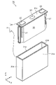
- FIG. 1 is a perspective view showing the appearance of a power storage device according to an embodiment.
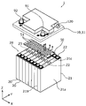
- FIG. 2 is an exploded perspective view showing a schematic configuration of the power storage device according to the embodiment.
- FIG. 3 is an exploded perspective view showing an overview of the configuration of the storage device according to the embodiment.
- FIG. 4 is a perspective view showing the configuration of the gas diffusion member and its surroundings according to the embodiment.
- FIG. 5 is a first cross-sectional view of the power storage device according to the embodiment.
- FIG. 6 is a second cross-sectional view of the power storage device according to the embodiment.
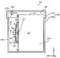
- FIG. 7 is a cross-sectional view of a power storage device according to Modification 1 of the embodiment.
- FIG. 8 is a cross-sectional view of a power storage device according to Modification 2 of the embodiment.
- FIG. 9 is a cross-sectional view of a power storage device according to Modification 3 of the embodiment.
- a power storage device includes: an exterior body; and a metal plate-like gas diffusion member arranged to face the gas discharge valves of the plurality of storage elements, wherein the gas diffusion member extends in the first direction.
- the gas ejected from the gas discharge valve collides with the gas diffusion member to disperse the pressure and lower the temperature.
- the gas diffusion member is arranged apart from other members (such as the lid of the exterior body) arranged on the first direction side of the plurality of power storage elements. Therefore, the heat of the gas diffusion member made of metal with high thermal conductivity is less likely to be transmitted to the other member. Therefore, the heat of the gas reduces the possibility that other members made of resin or the like will be weakened or melted.
- the gas ejected in the first direction and colliding with the gas diffusion member detours from at least both the second direction side and the third direction side of the gas diffusion member, It can spread in space on the direction side.
- the internal space of the exterior body can be widely used to diffuse the gas, and as a result, the pressure and temperature of the gas can be rapidly lowered.
- the power storage device of this aspect it is possible to suppress further deterioration of the state when an unsafe event occurs.
- the gas diffusion member may be formed with a plurality of through holes penetrating in the first direction.
- part of the gas that has collided with the gas diffusion member can penetrate the gas diffusion member. That is, since the flow direction of the gas that collides with the gas diffusion member increases, the pressure of the gas is efficiently dispersed, and the temperature of the gas is also efficiently lowered.
- the power storage device further includes a busbar holder that holds a busbar disposed on the first direction side of the plurality of power storage elements and electrically connected to the plurality of power storage elements, wherein the busbar holder supports the gas diffusion. It is also possible to have a supporting portion that supports the member while being separated from the plurality of power storage elements and the other member.
- the gas diffusion member can be supported by the busbar holder required for holding the busbar, etc., so there is no need to newly provide a dedicated member for arranging the gas diffusion member at a predetermined position.
- the exterior body has an exterior body body that houses the plurality of power storage elements, and a lid body that closes an opening of the exterior body body. It is also possible to have a supporting portion that supports the device in a suspended manner while being spaced apart from the other member.
- the gas diffusion member can be supported by the lid of the exterior body, so there is no need to newly provide a dedicated member for arranging the gas diffusion member at a predetermined position.
- the exterior body has an exhaust port for discharging the gas inside the exterior body to the outside, and the gas diffusion member is located between the gas exhaust valve and the exhaust port in the first direction. It may be arranged at a position.
- the gas ejected from the gas discharge valve in the first direction and diffused by the gas diffusion member is discharged from the opening located on the first direction side of the gas diffusion member to the outside of the exterior body. discharged to That is, the gas ejected from at least one gas exhaust valve and having its pressure (flow velocity) and temperature lowered by the gas diffusion member is efficiently exhausted to the outside of the exterior body.
- the direction in which a plurality of power storage elements are arranged is defined as the X-axis direction (except for Modification 3).
- the direction in which the electrode terminals of one storage element are arranged or the direction in which the short sides of the container of the storage element face each other is defined as the Y-axis direction (excluding Modifications 2 and 3).
- the direction in which the exterior main body and the lid are arranged in the exterior of the power storage device, or the vertical direction, is defined as the Z-axis direction.
- X-axis direction, Y-axis direction, and Z-axis direction are directions that intersect each other (hereinafter, orthogonally in the embodiment).
- the Z-axis direction may not be the vertical direction, but for convenience of explanation, the Z-axis direction will be described below as the vertical direction.
- expressions indicating relative directions or orientations such as parallel and orthogonal may be used, but strictly speaking, these expressions also include cases where the directions or orientations are not the same.
- two directions are parallel means not only that the two directions are completely parallel, but also substantially parallel, i.e., including a difference of about several percent also means
- the positive direction of the X-axis indicates the arrow direction of the X-axis
- the negative direction of the X-axis indicates the direction opposite to the positive direction of the X-axis.
- the Y-axis direction and the Z-axis direction The same applies to the Y-axis direction and the Z-axis direction.
- simply referring to the "X-axis direction” means either or both directions parallel to the X-axis. The same applies to terms relating to the Y-axis and Z-axis.
- FIG. 1 is a perspective view showing the appearance of a power storage device 1 according to an embodiment.
- FIG. 2 is an exploded perspective view showing a schematic configuration of the power storage device 1 according to the embodiment.
- FIG. 3 is an exploded perspective view showing a schematic configuration of the storage device 20 according to the embodiment.
- the power storage device 1 is a device that can charge electricity from the outside and discharge electricity to the outside, and has a substantially rectangular parallelepiped shape in the present embodiment.
- the power storage device 1 is a battery module (assembled battery) used for power storage or power supply.
- the power storage device 1 is, for example, an automobile, a motorcycle, a watercraft, a ship, a snowmobile, an agricultural machine, a construction machine, or a rolling stock for an electric railway. It is used as a battery etc.
- Examples of such vehicles include electric vehicles (EV), hybrid electric vehicles (HEV), plug-in hybrid electric vehicles (PHEV), and gasoline vehicles.
- Electric trains, monorails, and maglev trains are exemplified as railway vehicles for the electric railway.
- the power storage device 1 can also be used as a stationary battery or the like for home use or business use.
- the power storage device 1 includes a plurality of power storage elements 20 and an exterior body 10 that accommodates the plurality of power storage elements 20 .
- exterior body 10 accommodates eight power storage elements 20 .
- the number of power storage elements 20 included in power storage device 1 is not limited to eight.
- the power storage device 1 may include two or more power storage elements 20 .
- one storage element unit 28 is configured by a plurality of storage elements 20 arranged in the X-axis direction.
- the storage element unit 28 may have a spacer, an insulating film, and the like (not shown).
- the exterior body 10 has an exterior body body 12 that accommodates the power storage element unit 28 and a lid body 11 that closes an opening of the exterior body body 12 (body opening 15).
- a busbar holder 17 is arranged between the storage element unit 28 accommodated in the exterior body main body 12 and the lid body 11 .
- a plurality of busbars 33 are held in the busbar holder 17 .
- electrical devices such as a control circuit and a relay, electric wires, and the like may be arranged, but illustrations and descriptions thereof are omitted.
- the exterior body 10 is a rectangular (box-shaped) container (module case) that constitutes the outer shell of the power storage device 1 .
- the exterior body 10 is a member that fixes the electric storage element unit 28, the busbar holder 17, and the like at predetermined positions and protects them from impacts and the like.
- the exterior body 10 is made of, for example, polycarbonate (PC), polypropylene (PP), polyethylene (PE), polystyrene (PS), polyphenylene sulfide resin (PPS), polyphenylene ether (PPE (including modified PPE)), polyethylene terephthalate ( PET), polybutylene terephthalate (PBT), polyetheretherketone (PEEK), tetrafluoroethylene-perfluoroalkyl vinyl ether (PFA), polytetrafluoroethylene (PTFE), polyethersulfone (PES), ABS resin, or , an insulating member such as a composite material thereof, or a metal coated with an insulating coating.
- PC polycarbonate
- PP polypropylene
- PE polyethylene
- PS polystyrene
- PPS polyphenylene sulfide resin
- PPE polyphenylene ether
- PPE polyphenylene ether
- PET polyethylene terephthalate
- PBT poly
- the lid 11 of the exterior body 10 is a rectangular member that closes the body opening 15 of the exterior body 12 , and has a positive electrode side external terminal 91 and a negative electrode side external terminal 92 .
- the external terminals 91 and 92 are electrically connected to the plurality of power storage elements 20 via the busbars 33, and the power storage device 1 is charged with electricity from the outside via the external terminals 91 and 92, and Discharge electricity to the outside.
- the external terminals 91 and 92 are made of a conductive member made of metal such as aluminum or aluminum alloy.
- the exterior body 12 included in the exterior body 10 is a bottomed rectangular cylindrical housing in which a body opening 15 for accommodating the power storage element unit 28 is formed.
- the exterior body main body 12 has a pair of wall portions 14 facing each other in the X-axis direction and a pair of wall portions 13 facing each other in the Y-axis direction.
- a body opening 15 is formed by the upper ends of these four walls.
- the main body opening 15 and the lid 11 are joined without a gap by, for example, heat welding, bonding with an adhesive, or fastening with a gasket interposed.
- the storage element 20 is a secondary battery (single battery) capable of charging and discharging electricity, and more specifically, a non-aqueous electrolyte secondary battery such as a lithium ion secondary battery. .
- the storage element 20 may be a secondary battery other than a non-aqueous electrolyte secondary battery, or may be a capacitor.
- the storage element 20 may be a primary battery that allows the stored electricity to be used without being charged by the user.
- the storage element 20 may be a battery using a solid electrolyte.
- the storage element 20 may be a pouch-type storage element.
- the storage element 20 includes a flat rectangular parallelepiped (square) metal container 21 .
- the container 21 has a rectangular shape having a pair of long side surfaces 21a facing each other, a pair of short side surfaces 21b facing each other, and a terminal arrangement surface 21c connected to upper ends of the pair of long side surfaces 21a and the pair of short side surfaces 21b. is the case.
- the container 21 has a container body 25 and a cover plate 24 that closes the opening of the container body 25. 21a and a pair of short sides 21b are formed.
- the upper surface of the cover plate 24 forms a terminal arrangement surface 21c.
- the container main body 25 accommodates an electrode body 26, current collectors 27 on the positive electrode side and the negative electrode side, and an electrolytic solution (not shown).
- each of the plurality of power storage elements 20 is arranged in a row in the X-axis direction with the long side 21a facing the X-axis direction (the short side 21b is parallel to the X-axis direction).
- the electrode body 26 in the present embodiment is a wound electrode body formed by winding electrode plates (a positive electrode plate and a negative electrode plate) with separators interposed therebetween. Both ends of the electrode body 26 in the winding axis direction (Y-axis direction) are joined to leg portions of the current collector 27 .
- the electrode body provided in the storage element 20 is not limited to the wound type.
- the storage element 20 is provided with a laminated electrode body in which flat plate-shaped electrode plates are laminated, or an electrode body having a structure in which long strip-shaped electrode plates are laminated in a bellows shape by repeating mountain folds and valley folds.
- the posture of the electrode body does not need to be such that the winding axis direction is parallel to the Y-axis direction (the direction in which the pair of short side surfaces 21b face each other).
- the electrode body may be provided on the storage element 20 in a posture in which the winding axis direction is parallel to the Z-axis direction (longitudinal direction of the short side surface 21b).
- Metal electrode terminals 22 (a positive electrode terminal and a negative electrode terminal) electrically connected to the electrode body 26 inside the container body 25 via the current collector 27 are arranged on the terminal arrangement surface 21c of the cover plate 24. ing.
- the electrode terminal 22 is fixed to the cover plate 24 via a resin gasket (not shown), for example.
- a lid plate 24 of the container 21 is further provided with a gas discharge valve 23 for discharging the gas inside the container 21 to the outside. For example, when the internal pressure of the container 21 rises due to the vaporization of the electrolytic solution inside the container 21, the gas discharge valve 23 is opened (opened) to discharge the gas inside the container 21 to the outside of the container 21.
- the gas discharge valve 23 of each of the plurality of power storage elements 20 is oriented in the Z-axis plus direction, which is an example of the first direction.
- the X-axis direction which is the direction in which the plurality of storage elements 20 are arranged, is an example of a second direction that intersects the first direction
- the Y-axis direction is an example of a third direction that intersects the first direction and the second direction. be.
- the rectangular parallelepiped (square) power storage element 20 is illustrated, but the shape of the power storage element 20 is not limited to the rectangular parallelepiped shape, and may be a polygonal prism shape or the like other than the rectangular parallelepiped shape. .
- the busbar 33 is a rectangular plate-shaped member that is placed on at least two storage elements 20 while being held by the busbar holder 17 and electrically connects the electrode terminals 22 of the at least two storage elements 20 .
- the material of the bus bar 33 is not particularly limited, and may be formed of, for example, a metal such as aluminum, an aluminum alloy, copper, a copper alloy, a combination thereof, or a conductive member other than metal.
- five bus bars 33 are used to connect the energy storage elements 20 two by two in parallel to form four groups of energy storage elements 20, and the four groups of energy storage elements 20 are connected in series. Connected.
- the manner of electrical connection of the eight storage elements 20 is not particularly limited, and for example, all the eight storage elements 20 may be connected in series.
- the busbar holder 17 is a resin member that holds the busbar 33 .
- As the resin material for forming the busbar holder 17, PC, PP, PE, PS, PPS, or the like is adopted as in the exterior body 10.
- FIG. In this embodiment, the busbar holder 17 also serves to support the gas diffusion member 50, which will be described later.
- the busbar holder 17 is provided with a plurality of busbar openings 17 a that hold the plurality of busbars 33 and expose a portion of each of the plurality of busbars 33 toward the plurality of power storage elements 20 .
- the busbar holder 17 is further provided with an elongated exhaust opening 18 in the direction in which the plurality of storage elements 20 are arranged.
- the exhaust opening 18 is arranged in the power storage element unit 28 at a position facing the plurality of gas exhaust valves 23 arranged in the alignment direction. The gas discharged from these gas discharge valves 23 can pass through the busbar holder 17 in the Z-axis plus direction via the discharge opening 18 .
- a gas diffusion member 50 for diffusing the gas ejected from the gas discharge valves 23 when the gas discharge valves 23 are opened is provided at a position facing the plurality of gas discharge valves 23 .
- a plurality of support portions 19 are arranged around the exhaust opening 18 in the busbar holder 17, and the gas diffusion member 50 is supported by the plurality of support portions 19. there is thereby, the gas diffusion member 50 is arranged at a position separated from both the storage element unit 28 and the lid 11 in the Z-axis direction. That is, the gas traveling in the positive direction of the Z axis through the exhaust opening 18 is diffused in various directions by the gas diffusion member 50 disposed ahead.
- FIG. 4 is a perspective view showing the configuration of the gas diffusion member 50 and its surroundings according to the embodiment.
- FIG. 4 only the lid 11, the gas diffusion member 50, and the electric storage element unit 28 are illustrated, and each of them is illustrated separated in the Z-axis direction.
- Each of the hollow arrows and dotted arrows illustrated in FIG. 4 and subsequent figures schematically indicates the flow of the gas.
- FIG. 5 is a first cross-sectional view of power storage device 1 according to the embodiment
- FIG. 6 is a second cross-sectional view of power storage device 1 according to the embodiment.
- FIG. 5 simply illustrates a cross section of the power storage device 1 in the YZ plane passing through the IV-IV line in FIG.
- FIG. 5 simply illustrates a cross section of the power storage device 1 in the YZ plane passing through the IV-IV line in FIG.
- FIG. 6 simply illustrates a cross section of the power storage device 1 on the XZ plane passing through the VV line in FIG. 5 and 6 show the external shape of the storage element 20 when viewed from the X-axis direction or the Y-axis direction, and the approximate existence range of the gas discharge valve 23 is represented by a hatched rectangle. ing.
- the power storage device 1 includes a gas diffusion member 50 at a position facing the power storage element unit 28 having a plurality of power storage elements 20 .
- the gas diffusion members 50 are plate-shaped members made of metal, and are arranged side by side in the X-axis direction when viewed from the Z-axis positive direction (planar view) with the thickness direction facing the power storage element unit 28 . It is arranged at a position covering the plurality of gas discharge valves 23 .
- Metals forming the gas diffusion member 50 include iron, stainless steel, aluminum, and aluminum alloys. Therefore, the gas diffusion member 50 is not melted by the high-temperature (for example, about 400°) gas ejected from the gas discharge valve 23 when the valve is opened.
- the size and shape of the gas diffusion member 50 in plan view cover the plurality of gas discharge valves 23 and cover the storage element units 28 in the X-axis direction and the Y-axis direction. It has a size and shape that partially exposes.
- the gas diffusion member 50 is a rectangular member in plan view, but the shape in plan view may be a polygonal shape other than a rectangle, an elliptical shape, an oval shape, or the like.
- the position of the gas diffusion member 50 in the Z-axis direction is, as shown in FIGS. It is a position spaced apart from both.
- the power storage device 1 is housed in the exterior body 10 and the exterior body 10, each of which faces the first direction (Z-axis plus direction) with the gas discharge valve 23 facing in the second direction (X and a gas diffusion member 50 .
- the gas diffusion member 50 is a plate-like member made of metal arranged to face the gas discharge valves 23 of the plurality of power storage elements 20 .
- the gas diffusion member 50 is positioned between the plurality of storage elements 20 and the lid 11 , which is another member arranged at a position facing the plurality of storage elements 20 in the first direction, and is located between the plurality of storage elements 20 . 20 and lid body 11, respectively.
- the gas diffusion member 50 extends in the first direction both on the side of the gas diffusion member 50 in the second direction and on the side in the third direction (Y-axis direction) intersecting the first direction and the second direction. It is shaped and sized to allow the passage of gas.
- the gas ejected from the gas discharge valve 23 of the power storage element 20 collides with the gas diffusion member 50 to disperse the pressure. and its temperature drops.
- the gas diffusion member 50 is arranged apart from other members (cover 11 in the present embodiment) arranged on the first direction side of the plurality of power storage elements 20 . Therefore, the heat of the gas diffusion member 50 made of metal with high thermal conductivity is less likely to be transmitted to the lid body 11 . Therefore, the heat of the gas reduces the possibility that the strength of the lid 11 made of resin or the like is reduced or melted.
- the gas ejected in the first direction and colliding with the gas diffusion member 50 detours from at least the sides of the gas diffusion member 50 (both sides of the second direction and the third direction), and the gas diffuses. It can spread in the space on the first direction side of the member 50 . That is, the gas diffusion member 50 is not arranged so as to partition (partition) the space inside the exterior body 10 .
- the gas diffusion member 50 is formed in a shape and size that forms a space serving as a gas flow path on its side so that the gas that collides with the gas diffusion member 50 spreads over the gas diffusion member 50 .
- the internal space of the exterior body 10 can be widely used to diffuse the gas, and as a result, the pressure and temperature of the gas can be rapidly lowered.
- power storage device 1 of the present embodiment it is possible to suppress further deterioration of the state when an unsafe event occurs.
- the distance between the storage element 20 (more specifically, the gas discharge valve 23) and the gas diffusion member 50 in the first direction is set to suppress interference between the gas discharge valve 23 and the gas diffusion member 50 when the valve is open. , is preferably larger than half of the maximum outer dimension of the gas discharge valve 23 in plan view (the radius in the case of a circle). More preferably, the distance is larger than the maximum outer dimension (diameter in the case of a circle) of the gas exhaust valve 23 .
- the distance between the gas diffusion member 50 and another member (lid 11) in the first direction is preferably, for example, 1 mm or more in order to suppress heat conduction from the gas diffusion member 50 to the lid 11. More preferably, it is 5 mm or more.
- the temperature sensor may be arranged in contact with the gas diffusion member 50 .
- the gas diffusion member 50 which is made of metal and has high thermal conductivity, can be used to quickly detect a temperature rise when the valve is opened.
- the arrangement position of the gas diffusion member 50 is preferably the central portion of the gas diffusion member 50 in plan view.
- the gas diffusion member 50 is configured so that part of the gas that collides with the gas diffusion member 50 penetrates in the collision direction. Specifically, the gas diffusion member 50 is formed with a plurality of through holes 51 penetrating in the first direction. That is, as shown in FIGS. 4 to 6, the plate-like gas diffusion member 50 has a plurality of through-holes 51 penetrating in its thickness direction.
- the gas that has collided with the gas diffusion member 50 not only detours around the side of the gas diffusion member 50 and crosses the gas diffusion member 50, but also passes through the gas diffusion member 50 in the collision direction.
- the gas diffusion member 50 can be crossed by penetrating the diffusion member 50 . Since the gas diffusion member 50 is spaced apart from the lid 11 which is another member located directly above it, the gas that has passed over the gas diffusion member 50 is at least transmitted through the gas diffusion member 50 and the lid 11 .
- the plurality of through-holes 51 allow the gas diffusion member 50 to release pressure from the gas ejected from the gas discharge valve 23 , thereby suppressing deformation or damage of the gas diffusion member 50 due to the pressure of the gas. Therefore, for example, a relatively thin (low-rigidity) metal plate can be used as the base material of the gas diffusion member 50 , thereby reducing the weight of the power storage device 1 .
- the shape and size of the through hole 51 are not limited to a specific shape and size.
- Each of the plurality of through-holes 51 may be, for example, a circular hole with an inner diameter of about 1 to 5 mm, or a hole of any shape with a maximum inner dimension of 1 mm or less.
- the shape and size of the plurality of through holes 51 may not be uniform, and at least one of the shape and size may be random.
- the gas diffusion member 50 having a plurality of through-holes 51 does not need to be a plate-like metal plate with a plurality of through-holes 51 arranged in a matrix as shown in FIGS.
- a plate-shaped metal net or steel wool may be employed as the gas diffusion member 50 having a plurality of through-holes 51 .
- the power storage device 1 includes a busbar holder 17 that holds a busbar 33 that is arranged on the first direction side of the plurality of power storage elements 20 and electrically connected to the plurality of power storage elements 20 .
- the busbar holder 17 has a support portion 19 that supports the gas diffusion member 50 while being separated from the plurality of power storage elements 20 and the lid body 11 . More specifically, the busbar holder 17 has four support portions 19 distributed around the exhaust opening 18, and these four support portions 19 support the gas diffusion member 50 at four points. Support.
- the gas diffusion member 50 can be supported by the busbar holder 17 required for holding the busbar 33, etc., a dedicated member for arranging the gas diffusion member 50 at a predetermined position is newly provided. No need.
- the member having the support portion 19 that supports the gas diffusion member 50 while being separated from the gas discharge valve 23 and the lid body 11 is not limited to the busbar holder 17 .
- the support 19 may be provided in a tray or case that holds electrical equipment such as control circuits and relays.
- each of one or more rod-shaped (or string-shaped) members that connect the inner surface of the exterior main body 12 and the gas diffusion member 50 in the lateral direction (direction parallel to the XY plane) is the gas diffusion member 50.
- the supporting portion that supports the gas diffusion member 50 may be implemented by a member dedicated to supporting the gas diffusion member 50 .
- the exterior body 10 has an exhaust port 121 for discharging the gas inside the exterior body 10 to the outside.
- the gas diffusion member 50 is arranged at a position between the gas exhaust valve 23 and the exhaust port 121 in the first direction.
- a discharge port 121 is provided inside the cover 11 of the exterior body 10 .
- the exhaust port 121 is formed at a position communicating with an exhaust pipe 120 protruding from the outer surface of the lid 11 . That is, the gas that has flowed into the exhaust port 121 from the interior of the exterior body 10 passes through the exhaust pipe 120 and is discharged to the exterior of the exterior body 10 .
- the gas ejected in the first direction from the gas discharge valve 23 and diffused by the gas diffusion member 50 is discharged from the discharge port 121 positioned further in the first direction than the gas diffusion member 50, It is discharged to the outside of the exterior body 10 . That is, the gas ejected from at least one gas exhaust valve 23 and having its pressure (flow velocity) and temperature lowered by the gas diffusion member 50 is efficiently exhausted to the outside of the exterior body 10 .
- the power storage device 1 has been described above. good. Therefore, various modifications of the gas diffusion member 50 and its peripheral configuration will be described with reference to FIGS. 7 to 9, focusing on differences from the above embodiment.
- FIG. 7 is a cross-sectional view of a power storage device 1a according to Modification 1 of the embodiment. Supplementary matters such as the position of the cross section in FIG. 7 and the simplified illustration of the cross section conform to FIG. 5 described above. This also applies to FIGS. 8 and 9, which will be described later.
- the power storage device 1a according to this modification includes a gas diffusion member 50 made of metal and having a plate shape.
- the gas diffusion member 50 is arranged at a position between the lid body 11a and the plurality of power storage elements 20 and separated from the plurality of power storage elements 20 and the lid body 11a. These configurations are common to the power storage device 1 according to the embodiment.
- the power storage device 1a according to this modification differs from the power storage device 1 according to the embodiment in that the gas diffusion member 50 is supported by the support portion 19a provided on the lid 11a.
- the exterior body 10a has an exterior body main body 12a that accommodates a plurality of power storage elements 20 and a lid body 11a that closes the main body opening 15 .
- the lid body 11a has a support portion 19a that supports the gas diffusion member 50 in a suspended manner while being separated from the plurality of storage elements 20 and the lid body 11a, which is another member.
- the gas diffusion member 50 can be supported by the lid 11a of the exterior body 10, so there is no need to newly provide a dedicated member for arranging the gas diffusion member 50 at a predetermined position.
- each of one or more rod-shaped (or string-shaped) members connecting the inner surface of the lid 11a and the gas diffusion member 50 in the lateral direction separates the gas diffusion member 50 from the gas discharge valve 23 and the lid 11a.
- FIG. 8 is a cross-sectional view of a power storage device 1b according to Modification 2 of the embodiment.
- a power storage device 1b according to this modification includes a power storage element unit 28 having a plurality of power storage elements 20 arranged in the X-axis direction, and an exterior body 10b that accommodates the power storage element unit 28.
- the exterior body 10b has an exterior body main body 12b and a lid body 11b.
- the plurality of power storage elements 20 and the wall portion 13b (of the exterior main body 12b), which is another member are positioned facing the gas discharge valves 23 of the power storage elements 20.
- a plate-shaped gas diffusion member 50 made of metal is arranged between the wall portion 13b).
- the gas diffusion member 50 is arranged at a position separated from each of the plurality of power storage elements 20 and the wall portion 13b. Spaces in which gas can move are formed in the vertical direction (Z-axis direction) and sideways (directions parallel to the XY plane) of the gas diffusion member 50 .
- the power storage device 1b according to this modification has a configuration common to that of the power storage device 1 according to the embodiment.
- the power storage device 1b according to the present modification differs from the power storage device 1 according to the embodiment in that each of the plurality of power storage elements 20 is arranged with the gas discharge valve 23 directed in the positive direction of the Y axis. different. More specifically, the plurality of power storage elements 20 are arranged in the X-axis direction with the gas discharge valve 23 directed in the Y-axis plus direction and the long side surface 21a directed in the X-axis direction.
- the description of the configuration is as follows. This is common with the description of the configuration of the power storage device 1 according to the embodiment. That is, the power storage device 1b is housed in the exterior body 10b and the exterior body 10b, each of which has a posture in which the gas discharge valve 23 is directed in the first direction (Y-axis plus direction), and in the second direction intersecting the first direction. It includes a plurality of power storage elements 20 arranged in the (X-axis direction) and a gas diffusion member 50 .
- the gas diffusion member 50 is positioned between the plurality of storage elements 20 and the wall portion 13b arranged at a position facing the plurality of storage elements 20 in the first direction, and is located between the plurality of storage elements 20 and the wall portion 13b. are arranged at positions separated from each other.
- the gas diffusion member 50 extends in the first direction both on the side of the gas diffusion member 50 in the second direction and on the side in the third direction (Z-axis direction) intersecting the first direction and the second direction. It is shaped and sized to allow the passage of gas.
- the pressure and temperature of the gas ejected from the gas discharge valve 23 can be quickly reduced by the gas diffusion member 50, as in the power storage device 1 according to the embodiment. can be done. This suppresses deterioration in strength, melting, or the like of the exterior body 10b. Therefore, according to the power storage device 1b, it is possible to suppress further deterioration of the state when an unsafe event occurs.
- FIG. 9 is a cross-sectional view of a power storage device 1c according to Modification 3 of the embodiment.
- a power storage device 1c according to this modification includes a power storage element unit 28 having a plurality of power storage elements 20 arranged in the Z-axis direction, and an exterior body 10c that accommodates the power storage element unit 28.
- the exterior body 10c has an exterior body main body 12c and a lid body 11c.
- the plurality of power storage elements 20 and the wall portion 13c (of the exterior main body 12c), which is another member, are located opposite the gas discharge valves 23 of the power storage elements 20.
- a plate-like gas diffusion member 50 made of metal is arranged between the wall portion 13c).
- the gas diffusion member 50 is arranged at a position separated from each of the plurality of power storage elements 20 and the wall portion 13c. Spaces in which gas can move are formed in the vertical direction (Z-axis direction) and sideways (directions parallel to the XY plane) of the gas diffusion member 50 .
- the power storage device 1c according to this modification has a configuration common to that of the power storage device 1 according to the embodiment.
- the power storage device 1c according to the present modification differs from the power storage device 1 according to the embodiment in that each of the plurality of power storage elements 20 is arranged with the gas discharge valve 23 directed in the positive direction of the Y axis. different. More specifically, the plurality of power storage elements 20 are arranged in the Z-axis direction with the gas discharge valve 23 directed in the Y-axis positive direction and the short side surface 21b directed in the X-axis direction. That is, in this modified example, the plurality of power storage elements 20 are stacked vertically.
- the description of the configuration is as follows. This is common with the description of the configuration of the power storage device 1 according to the embodiment. That is, the power storage device 1c is housed in the exterior body 10c and the exterior body 10c, each of which is in a posture in which the gas discharge valve 23 is directed in the first direction (Y-axis plus direction), and in the second direction intersecting the first direction. It includes a plurality of power storage elements 20 arranged in the (Z-axis direction) and a gas diffusion member 50 .
- the gas diffusion member 50 is positioned between the plurality of storage elements 20 and the wall portion 13b arranged at a position facing the plurality of storage elements 20 in the first direction, and is located between the plurality of storage elements 20 and the wall portion 13b. are arranged at positions separated from each other.
- the gas diffusion member 50 extends in the first direction both on the side of the gas diffusion member 50 in the second direction and on the side in the third direction (X-axis direction) intersecting the first direction and the second direction. It is shaped and sized to allow the passage of gas.
- the gas diffusion member 50 quickly reduces the pressure and temperature of the gas ejected from the gas discharge valve 23, as in the power storage device 1 according to the embodiment. be able to. This suppresses deterioration in strength, melting, or the like of the exterior body 10c. Therefore, according to the power storage device 1c, it is possible to suppress further deterioration of the state when an unsafe event occurs.
- other members arranged in the first direction which is the direction in which the gas discharge valve 23 is directed with respect to the electric storage element 20 , need not be part of the exterior body 10 .
- a control device or an electric device such as a relay, or a tray or the like for holding the electric device is arranged at a position facing the gas discharge valve 23 in the first direction
- another member such as a tray or an electric device, is arranged. and the storage element 20, the gas diffusion member 50 is arranged.
- the gas diffusion member 50 is arranged.
- the gas diffusion member 50 when a member formed of a material (resin or the like) having a lower melting point than the gas diffusion member 50 is arranged as another member, the gas diffusion member 50 is arranged apart from the other member. , the other member can be protected from the gas while obtaining the effect of lowering the pressure and temperature of the gas by the gas diffusion member 50 . That is, for example, in the structures shown in FIGS. 4 to 6, even if an electrical device is placed between the gas diffusion member 50 and the lid 11, the electrical device can be , from the gas ejected from the gas discharge valve 23 . Furthermore, the gas diffusion member 50 can widely utilize the internal space of the exterior body 10 to diffuse the gas, and as a result, the pressure and temperature of the gas are efficiently lowered.
- the gas diffusion member 50 does not need to have a shape and size that collectively cover the plurality of gas discharge valves 23 in plan view.
- a separate gas diffusion member may be arranged for each of the plurality of gas discharge valves 23 . Even in this case, if spaces through which the gas can pass are formed in the upper, lower, left, and right sides of the gas diffusion member, the internal space of the exterior body 10 can be widely used to diffuse the gas.
- the gas diffusion member 50 does not need to be supported by a member other than the electric storage element 20, such as the busbar holder 17, and may be supported by the electric storage element 20. For example, by fixing one or more legs extending from the gas diffusion member 50 toward the storage element unit 28 to the terminal arrangement surface 21c (see FIG. 3) of the one or more storage elements 20 with an adhesive or the like. , the gas diffusion member 50 may be arranged with respect to the electric storage element unit 28 . As described above, when an individual gas diffusion member is arranged for each of the multiple gas discharge valves 23, each of the multiple storage elements 20 may support the gas diffusion member corresponding to the storage element 20. .
- a form constructed by arbitrarily combining the plurality of components described above is also included within the scope of the present invention.
- various supplementary matters regarding power storage device 1 according to the above-described embodiment may be applied to any one of power storage devices 1a to 1c according to modified examples 1 to 3.
- the present invention can be applied to a power storage device having a power storage element such as a lithium ion secondary battery.
Landscapes
- Chemical & Material Sciences (AREA)
- Chemical Kinetics & Catalysis (AREA)
- Electrochemistry (AREA)
- General Chemical & Material Sciences (AREA)
- Engineering & Computer Science (AREA)
- Power Engineering (AREA)
- Microelectronics & Electronic Packaging (AREA)
- Electric Double-Layer Capacitors Or The Like (AREA)
- Gas Exhaust Devices For Batteries (AREA)
Abstract
L'invention concerne un dispositif de stockage d'énergie qui est équipé : d'un corps externe ; d'une pluralité d'éléments de stockage d'énergie qui sont agencés dans une deuxième direction perpendiculaire à une première direction dans une orientation dans laquelle la soupape d'évacuation de gaz de chacune fait face à la première direction ; et un élément de diffusion de gaz. L'élément de diffusion de gaz est un élément en forme de plaque métallique positionné de façon à faire face aux soupapes de décharge de gaz de la pluralité d'éléments de stockage d'énergie. L'élément de diffusion de gaz est positionné : dans un emplacement entre la pluralité d'éléments de stockage d'énergie et un couvercle, qui est un autre élément positionné dans un emplacement faisant face à la pluralité d'éléments de stockage d'énergie dans la première direction ; et dans un emplacement qui est séparé de chacun de la pluralité d'éléments de stockage d'énergie et à partir du couvercle. L'élément de diffusion de gaz est formé selon une forme et une dimension qui permettent le passage d'un gaz dans la première direction à la fois sur le côté de l'élément de diffusion de gaz dans la deuxième direction et sur le côté de l'élément de diffusion de gaz dans une troisième direction qui croise les première et deuxième directions.
Priority Applications (1)
| Application Number | Priority Date | Filing Date | Title |
|---|---|---|---|
| JP2022576753A JP7852515B2 (ja) | 2021-01-25 | 2022-01-21 | 蓄電装置 |
Applications Claiming Priority (2)
| Application Number | Priority Date | Filing Date | Title |
|---|---|---|---|
| JP2021009697 | 2021-01-25 | ||
| JP2021-009697 | 2021-01-25 |
Publications (1)
| Publication Number | Publication Date |
|---|---|
| WO2022158552A1 true WO2022158552A1 (fr) | 2022-07-28 |
Family
ID=82548756
Family Applications (1)
| Application Number | Title | Priority Date | Filing Date |
|---|---|---|---|
| PCT/JP2022/002105 Ceased WO2022158552A1 (fr) | 2021-01-25 | 2022-01-21 | Dispositif de stockage d'énergie |
Country Status (2)
| Country | Link |
|---|---|
| JP (1) | JP7852515B2 (fr) |
| WO (1) | WO2022158552A1 (fr) |
Cited By (3)
| Publication number | Priority date | Publication date | Assignee | Title |
|---|---|---|---|---|
| JP2025004606A (ja) * | 2023-06-26 | 2025-01-15 | プライムプラネットエナジー&ソリューションズ株式会社 | 電池パック |
| JP2025004607A (ja) * | 2023-06-26 | 2025-01-15 | プライムプラネットエナジー&ソリューションズ株式会社 | 電池パック |
| WO2026012533A1 (fr) * | 2024-07-11 | 2026-01-15 | Bayerische Motoren Werke Aktiengesellschaft | Dispositif de stockage haute tension pour un véhicule à moteur |
Citations (5)
| Publication number | Priority date | Publication date | Assignee | Title |
|---|---|---|---|---|
| JP2010055957A (ja) * | 2008-08-28 | 2010-03-11 | Sanyo Electric Co Ltd | パック電池 |
| JP2016033908A (ja) * | 2014-07-31 | 2016-03-10 | 株式会社Gsユアサ | 電源パック |
| JP2019197622A (ja) * | 2018-05-08 | 2019-11-14 | トヨタ自動車株式会社 | 電池パック |
| WO2020152992A1 (fr) * | 2019-01-25 | 2020-07-30 | 三洋電機株式会社 | Bloc-batterie |
| CN111540977A (zh) * | 2020-04-21 | 2020-08-14 | 华南理工大学 | 一种动力电池液冷型热管理系统及吹胀型铝质均热板 |
Family Cites Families (1)
| Publication number | Priority date | Publication date | Assignee | Title |
|---|---|---|---|---|
| JP6784099B2 (ja) * | 2016-08-30 | 2020-11-11 | 株式会社豊田自動織機 | 電池パック |
-
2022
- 2022-01-21 WO PCT/JP2022/002105 patent/WO2022158552A1/fr not_active Ceased
- 2022-01-21 JP JP2022576753A patent/JP7852515B2/ja active Active
Patent Citations (5)
| Publication number | Priority date | Publication date | Assignee | Title |
|---|---|---|---|---|
| JP2010055957A (ja) * | 2008-08-28 | 2010-03-11 | Sanyo Electric Co Ltd | パック電池 |
| JP2016033908A (ja) * | 2014-07-31 | 2016-03-10 | 株式会社Gsユアサ | 電源パック |
| JP2019197622A (ja) * | 2018-05-08 | 2019-11-14 | トヨタ自動車株式会社 | 電池パック |
| WO2020152992A1 (fr) * | 2019-01-25 | 2020-07-30 | 三洋電機株式会社 | Bloc-batterie |
| CN111540977A (zh) * | 2020-04-21 | 2020-08-14 | 华南理工大学 | 一种动力电池液冷型热管理系统及吹胀型铝质均热板 |
Cited By (6)
| Publication number | Priority date | Publication date | Assignee | Title |
|---|---|---|---|---|
| JP2025004606A (ja) * | 2023-06-26 | 2025-01-15 | プライムプラネットエナジー&ソリューションズ株式会社 | 電池パック |
| JP2025004607A (ja) * | 2023-06-26 | 2025-01-15 | プライムプラネットエナジー&ソリューションズ株式会社 | 電池パック |
| JP7748421B2 (ja) | 2023-06-26 | 2025-10-02 | プライムプラネットエナジー&ソリューションズ株式会社 | 電池パック |
| JP7774017B2 (ja) | 2023-06-26 | 2025-11-20 | プライムプラネットエナジー&ソリューションズ株式会社 | 電池パック |
| WO2026012533A1 (fr) * | 2024-07-11 | 2026-01-15 | Bayerische Motoren Werke Aktiengesellschaft | Dispositif de stockage haute tension pour un véhicule à moteur |
| DE102024119681A1 (de) * | 2024-07-11 | 2026-01-15 | Bayerische Motoren Werke Aktiengesellschaft | Hochvoltspeicher für ein Kraftfahrzeug |
Also Published As
| Publication number | Publication date |
|---|---|
| JP7852515B2 (ja) | 2026-04-28 |
| JPWO2022158552A1 (fr) | 2022-07-28 |
Similar Documents
| Publication | Publication Date | Title |
|---|---|---|
| WO2022158552A1 (fr) | Dispositif de stockage d'énergie | |
| JP2013069417A (ja) | 二次電池 | |
| JP2022549321A (ja) | バスバーを備えたバッテリーモジュール、バッテリーパック、及び自動車 | |
| WO2022009564A1 (fr) | Dispositif de stockage d'énergie | |
| JP7263378B2 (ja) | 電池モジュール | |
| WO2023223961A1 (fr) | Dispositif de stockage d'énergie | |
| JP7800430B2 (ja) | 蓄電装置 | |
| CN116964832A (zh) | 蓄电装置 | |
| WO2023048040A1 (fr) | Dispositif de stockage d'énergie | |
| WO2024043254A1 (fr) | Dispositif de stockage d'énergie | |
| JP2023100001A (ja) | 蓄電装置 | |
| JP2024068439A (ja) | 蓄電装置 | |
| JP2024021509A (ja) | 蓄電装置 | |
| JP2024021469A (ja) | 蓄電装置 | |
| WO2022255162A1 (fr) | Dispositif de stockage d'énergie | |
| US20240372204A1 (en) | Energy storage apparatus | |
| JP7834986B2 (ja) | 蓄電装置 | |
| EP4693667A1 (fr) | Dispositif de stockage d'énergie | |
| US20260011856A1 (en) | Energy storage apparatus | |
| JP7669654B2 (ja) | 蓄電装置 | |
| JP2025085276A (ja) | 蓄電装置 | |
| WO2025173630A1 (fr) | Dispositif de stockage d'énergie | |
| JP2025038646A (ja) | 蓄電装置 | |
| KR20250150800A (ko) | 배터리 모듈, 이를 포함하는 배터리 팩 및 자동차 | |
| JP2023094757A (ja) | 蓄電装置 |
Legal Events
| Date | Code | Title | Description |
|---|---|---|---|
| 121 | Ep: the epo has been informed by wipo that ep was designated in this application |
Ref document number: 22742671 Country of ref document: EP Kind code of ref document: A1 |
|
| ENP | Entry into the national phase |
Ref document number: 2022576753 Country of ref document: JP Kind code of ref document: A |
|
| NENP | Non-entry into the national phase |
Ref country code: DE |
|
| 122 | Ep: pct application non-entry in european phase |
Ref document number: 22742671 Country of ref document: EP Kind code of ref document: A1 |