WO2022158574A1 - 熱交換器 - Google Patents
熱交換器 Download PDFInfo
- Publication number
- WO2022158574A1 WO2022158574A1 PCT/JP2022/002237 JP2022002237W WO2022158574A1 WO 2022158574 A1 WO2022158574 A1 WO 2022158574A1 JP 2022002237 W JP2022002237 W JP 2022002237W WO 2022158574 A1 WO2022158574 A1 WO 2022158574A1
- Authority
- WO
- WIPO (PCT)
- Prior art keywords
- heat
- heat transfer
- transfer tube
- heat exchanger
- refrigerant
- Prior art date
- Legal status (The legal status is an assumption and is not a legal conclusion. Google has not performed a legal analysis and makes no representation as to the accuracy of the status listed.)
- Ceased
Links
Images



Classifications
-
- F—MECHANICAL ENGINEERING; LIGHTING; HEATING; WEAPONS; BLASTING
- F28—HEAT EXCHANGE IN GENERAL
- F28D—HEAT-EXCHANGE APPARATUS, NOT PROVIDED FOR IN ANOTHER SUBCLASS, IN WHICH THE HEAT-EXCHANGE MEDIA DO NOT COME INTO DIRECT CONTACT
- F28D1/00—Heat-exchange apparatus having stationary conduit assemblies for one heat-exchange medium only, the media being in contact with different sides of the conduit wall, in which the other heat-exchange medium is a large body of fluid, e.g. domestic or motor car radiators
- F28D1/02—Heat-exchange apparatus having stationary conduit assemblies for one heat-exchange medium only, the media being in contact with different sides of the conduit wall, in which the other heat-exchange medium is a large body of fluid, e.g. domestic or motor car radiators with heat-exchange conduits immersed in the body of fluid
- F28D1/0233—Heat-exchange apparatus having stationary conduit assemblies for one heat-exchange medium only, the media being in contact with different sides of the conduit wall, in which the other heat-exchange medium is a large body of fluid, e.g. domestic or motor car radiators with heat-exchange conduits immersed in the body of fluid with air flow channels
- F28D1/024—Heat-exchange apparatus having stationary conduit assemblies for one heat-exchange medium only, the media being in contact with different sides of the conduit wall, in which the other heat-exchange medium is a large body of fluid, e.g. domestic or motor car radiators with heat-exchange conduits immersed in the body of fluid with air flow channels with an air driving element
-
- F—MECHANICAL ENGINEERING; LIGHTING; HEATING; WEAPONS; BLASTING
- F25—REFRIGERATION OR COOLING; COMBINED HEATING AND REFRIGERATION SYSTEMS; HEAT PUMP SYSTEMS; MANUFACTURE OR STORAGE OF ICE; LIQUEFACTION SOLIDIFICATION OF GASES
- F25B—REFRIGERATION MACHINES, PLANTS OR SYSTEMS; COMBINED HEATING AND REFRIGERATION SYSTEMS; HEAT PUMP SYSTEMS
- F25B13/00—Compression machines, plants or systems, with reversible cycle
-
- F—MECHANICAL ENGINEERING; LIGHTING; HEATING; WEAPONS; BLASTING
- F25—REFRIGERATION OR COOLING; COMBINED HEATING AND REFRIGERATION SYSTEMS; HEAT PUMP SYSTEMS; MANUFACTURE OR STORAGE OF ICE; LIQUEFACTION SOLIDIFICATION OF GASES
- F25B—REFRIGERATION MACHINES, PLANTS OR SYSTEMS; COMBINED HEATING AND REFRIGERATION SYSTEMS; HEAT PUMP SYSTEMS
- F25B39/00—Evaporators; Condensers
-
- F—MECHANICAL ENGINEERING; LIGHTING; HEATING; WEAPONS; BLASTING
- F25—REFRIGERATION OR COOLING; COMBINED HEATING AND REFRIGERATION SYSTEMS; HEAT PUMP SYSTEMS; MANUFACTURE OR STORAGE OF ICE; LIQUEFACTION SOLIDIFICATION OF GASES
- F25B—REFRIGERATION MACHINES, PLANTS OR SYSTEMS; COMBINED HEATING AND REFRIGERATION SYSTEMS; HEAT PUMP SYSTEMS
- F25B41/00—Fluid-circulation arrangements
- F25B41/20—Disposition of valves, e.g. of on-off valves or flow control valves
- F25B41/24—Arrangement of shut-off valves for disconnecting a part of the refrigerant cycle, e.g. an outdoor part
-
- F—MECHANICAL ENGINEERING; LIGHTING; HEATING; WEAPONS; BLASTING
- F25—REFRIGERATION OR COOLING; COMBINED HEATING AND REFRIGERATION SYSTEMS; HEAT PUMP SYSTEMS; MANUFACTURE OR STORAGE OF ICE; LIQUEFACTION SOLIDIFICATION OF GASES
- F25B—REFRIGERATION MACHINES, PLANTS OR SYSTEMS; COMBINED HEATING AND REFRIGERATION SYSTEMS; HEAT PUMP SYSTEMS
- F25B49/00—Arrangement or mounting of control or safety devices
- F25B49/02—Arrangement or mounting of control or safety devices for compression type machines, plants or systems
-
- F—MECHANICAL ENGINEERING; LIGHTING; HEATING; WEAPONS; BLASTING
- F28—HEAT EXCHANGE IN GENERAL
- F28D—HEAT-EXCHANGE APPARATUS, NOT PROVIDED FOR IN ANOTHER SUBCLASS, IN WHICH THE HEAT-EXCHANGE MEDIA DO NOT COME INTO DIRECT CONTACT
- F28D1/00—Heat-exchange apparatus having stationary conduit assemblies for one heat-exchange medium only, the media being in contact with different sides of the conduit wall, in which the other heat-exchange medium is a large body of fluid, e.g. domestic or motor car radiators
- F28D1/02—Heat-exchange apparatus having stationary conduit assemblies for one heat-exchange medium only, the media being in contact with different sides of the conduit wall, in which the other heat-exchange medium is a large body of fluid, e.g. domestic or motor car radiators with heat-exchange conduits immersed in the body of fluid
- F28D1/04—Heat-exchange apparatus having stationary conduit assemblies for one heat-exchange medium only, the media being in contact with different sides of the conduit wall, in which the other heat-exchange medium is a large body of fluid, e.g. domestic or motor car radiators with heat-exchange conduits immersed in the body of fluid with tubular conduits
- F28D1/0408—Multi-circuit heat exchangers, e.g. integrating different heat exchange sections in the same unit or heat exchangers for more than two fluids
- F28D1/0426—Multi-circuit heat exchangers, e.g. integrating different heat exchange sections in the same unit or heat exchangers for more than two fluids with units having particular arrangement relative to the large body of fluid, e.g. with interleaved units or with adjacent heat exchange units in common air flow or with units extending at an angle to each other or with units arranged around a central element
- F28D1/0435—Combination of units extending one behind the other
-
- F—MECHANICAL ENGINEERING; LIGHTING; HEATING; WEAPONS; BLASTING
- F28—HEAT EXCHANGE IN GENERAL
- F28D—HEAT-EXCHANGE APPARATUS, NOT PROVIDED FOR IN ANOTHER SUBCLASS, IN WHICH THE HEAT-EXCHANGE MEDIA DO NOT COME INTO DIRECT CONTACT
- F28D1/00—Heat-exchange apparatus having stationary conduit assemblies for one heat-exchange medium only, the media being in contact with different sides of the conduit wall, in which the other heat-exchange medium is a large body of fluid, e.g. domestic or motor car radiators
- F28D1/02—Heat-exchange apparatus having stationary conduit assemblies for one heat-exchange medium only, the media being in contact with different sides of the conduit wall, in which the other heat-exchange medium is a large body of fluid, e.g. domestic or motor car radiators with heat-exchange conduits immersed in the body of fluid
- F28D1/04—Heat-exchange apparatus having stationary conduit assemblies for one heat-exchange medium only, the media being in contact with different sides of the conduit wall, in which the other heat-exchange medium is a large body of fluid, e.g. domestic or motor car radiators with heat-exchange conduits immersed in the body of fluid with tubular conduits
- F28D1/047—Heat-exchange apparatus having stationary conduit assemblies for one heat-exchange medium only, the media being in contact with different sides of the conduit wall, in which the other heat-exchange medium is a large body of fluid, e.g. domestic or motor car radiators with heat-exchange conduits immersed in the body of fluid with tubular conduits the conduits being bent, e.g. in a serpentine or zig-zag
- F28D1/0477—Heat-exchange apparatus having stationary conduit assemblies for one heat-exchange medium only, the media being in contact with different sides of the conduit wall, in which the other heat-exchange medium is a large body of fluid, e.g. domestic or motor car radiators with heat-exchange conduits immersed in the body of fluid with tubular conduits the conduits being bent, e.g. in a serpentine or zig-zag the conduits being bent in a serpentine or zig-zag
-
- F—MECHANICAL ENGINEERING; LIGHTING; HEATING; WEAPONS; BLASTING
- F28—HEAT EXCHANGE IN GENERAL
- F28F—DETAILS OF HEAT-EXCHANGE AND HEAT-TRANSFER APPARATUS, OF GENERAL APPLICATION
- F28F9/00—Casings; Header boxes; Auxiliary supports for elements; Auxiliary members within casings
- F28F9/02—Header boxes; End plates
- F28F9/026—Header boxes; End plates with static flow control means, e.g. with means for uniformly distributing heat exchange media into conduits
- F28F9/027—Header boxes; End plates with static flow control means, e.g. with means for uniformly distributing heat exchange media into conduits in the form of distribution pipes
- F28F9/0275—Header boxes; End plates with static flow control means, e.g. with means for uniformly distributing heat exchange media into conduits in the form of distribution pipes with multiple branch pipes
-
- F—MECHANICAL ENGINEERING; LIGHTING; HEATING; WEAPONS; BLASTING
- F25—REFRIGERATION OR COOLING; COMBINED HEATING AND REFRIGERATION SYSTEMS; HEAT PUMP SYSTEMS; MANUFACTURE OR STORAGE OF ICE; LIQUEFACTION SOLIDIFICATION OF GASES
- F25B—REFRIGERATION MACHINES, PLANTS OR SYSTEMS; COMBINED HEATING AND REFRIGERATION SYSTEMS; HEAT PUMP SYSTEMS
- F25B2313/00—Compression machines, plants or systems with reversible cycle not otherwise provided for
- F25B2313/029—Control issues
- F25B2313/0292—Control issues related to reversing valves
-
- F—MECHANICAL ENGINEERING; LIGHTING; HEATING; WEAPONS; BLASTING
- F25—REFRIGERATION OR COOLING; COMBINED HEATING AND REFRIGERATION SYSTEMS; HEAT PUMP SYSTEMS; MANUFACTURE OR STORAGE OF ICE; LIQUEFACTION SOLIDIFICATION OF GASES
- F25B—REFRIGERATION MACHINES, PLANTS OR SYSTEMS; COMBINED HEATING AND REFRIGERATION SYSTEMS; HEAT PUMP SYSTEMS
- F25B2600/00—Control issues
- F25B2600/25—Control of valves
- F25B2600/2507—Flow-diverting valves
-
- F—MECHANICAL ENGINEERING; LIGHTING; HEATING; WEAPONS; BLASTING
- F28—HEAT EXCHANGE IN GENERAL
- F28D—HEAT-EXCHANGE APPARATUS, NOT PROVIDED FOR IN ANOTHER SUBCLASS, IN WHICH THE HEAT-EXCHANGE MEDIA DO NOT COME INTO DIRECT CONTACT
- F28D21/00—Heat-exchange apparatus not covered by any of the groups F28D1/00 - F28D20/00
- F28D2021/0019—Other heat exchangers for particular applications; Heat exchange systems not otherwise provided for
- F28D2021/0068—Other heat exchangers for particular applications; Heat exchange systems not otherwise provided for for refrigerant cycles
-
- F—MECHANICAL ENGINEERING; LIGHTING; HEATING; WEAPONS; BLASTING
- F28—HEAT EXCHANGE IN GENERAL
- F28F—DETAILS OF HEAT-EXCHANGE AND HEAT-TRANSFER APPARATUS, OF GENERAL APPLICATION
- F28F2210/00—Heat exchange conduits
- F28F2210/10—Particular layout, e.g. for uniform temperature distribution
Definitions
- a heat exchanger that constitutes a refrigerant circuit of an air conditioner is known.
- Patent Document 1 JP-A-1-3052766 discloses a heat exchanger comprising a plurality of pipes (heat transfer pipes) and branch pipes connected to the pipes.
- the plurality of pipes are arranged side by side on the windward side and the leeward side of the wind generated by the fan.
- the branch pipe has one inlet pipe and two branch ports, and the refrigerant flowing from the inlet pipe flows through the two branch ports to the pipe arranged on the windward side and the pipe arranged on the leeward side.
- the present disclosure proposes a heat exchanger capable of improving capacity while suppressing increases in manufacturing costs.
- the heat exchanger of the first aspect includes a first heat transfer tube, a second heat transfer tube, and a flow dividing tube.
- the flow dividing tube has a first end connected to the end of the first heat transfer tube, a second end connected to the end of the second heat transfer tube, and a third end.
- a flow diverter tube connects the first end, the second end and the third end to each other.
- the amount of heat exchanged in the first heat transfer tube is greater than the amount of heat exchanged in the second heat transfer tube.
- the length of the first flow path connecting the first end and the third end is shorter than the length of the second flow path connecting the second end and the third end.
- the pressure loss suffered by the refrigerant flowing through the first flow path is the pressure loss suffered by the refrigerant flowing through the second flow path. small compared to Therefore, the flow rate of the refrigerant flowing through the branch pipe into the first heat transfer tube is greater than that of the refrigerant flowing into the second heat transfer pipe through the branch pipe.
- the heat exchanger it is possible to improve the capacity while suppressing the increase in manufacturing cost by using the branch pipe with a simple structure.
- the heat exchanger of the second aspect is the heat exchanger of the first aspect, in which the first heat transfer tubes are arranged on the windward side of the second heat transfer tubes.
- the heat exchanger of the third aspect is the heat exchanger of the first aspect or the second aspect, further comprising a third heat transfer tube connected to the third end.
- the heat exchanger according to the fourth aspect is the heat exchanger according to the third aspect, and the third heat transfer tube is arranged on the windward side of the first heat transfer tube.
- a heat exchanger according to a fifth aspect is the heat exchanger according to any one of the first aspect to the fourth aspect, wherein the ratio of the length of the first flow path to the length of the second flow path is the length of the first heat transfer tube. It corresponds to the ratio of the heat exchange amount and the heat exchange amount of the second heat transfer tube.
- the amount of refrigerant flowing out from the first end and the amount of refrigerant flowing out from the second end are the pressure loss received by the refrigerant in the first flow path and the pressure loss in the second flow path. It is determined by the pressure loss that the refrigerant receives at Therefore, the ratio between the amount of refrigerant flowing into the first heat transfer tube and the amount of refrigerant flowing into the second heat transfer tube is determined by the ratio of the length of the first flow path to the length of the second flow path. .
- the tubes can reduce the difference in superheat between the central heat exchange section and the leeward heat exchange section, providing a higher capacity heat exchanger.
- a heat exchanger is the heat exchanger according to any one of the first aspect to the fifth aspect, wherein the branch pipe has a U-shaped portion and an inflow portion having one end connected to the U-shaped portion. .
- the U-shaped portion has a bent portion, a first straight portion and a second straight portion.
- the bending portion bends with a predetermined radius.
- the first linear portion extends linearly from one end of the bent portion.
- the second straight portion extends linearly from the other end of the bent portion.
- the end of the first linear portion opposite to the bent portion is the first end.
- the end of the second linear portion opposite to the bent portion is the second end.
- the inflow portion has one end connected to the first straight portion and the other end serving as the third end.
- the first flow path includes an inflow portion and a portion of the first straight portion.
- the second flow path includes an inflow portion, a portion of the curved portion, and a second straight portion.
- the branch pipe has a simple structure consisting of the U-shaped portion and the inflow portion, so it can be manufactured at low cost. Also, the lengths of the first flow path and the second flow path can be easily adjusted by changing the attachment position of the inflow portion to the U-shaped portion.
- the heat exchanger according to the seventh aspect is the heat exchanger according to the sixth aspect, and has a third straight portion linearly extending from a portion connected to the first straight portion.
- the angle on the first end side is 90° or more and 135° or less.
- the first flow path is more flexible than when the angle is smaller than 90°.
- the coolant passing through smoothly flows into the first linear portion from the inflow portion. Therefore, a large flow rate of the refrigerant flowing into the first heat transfer tubes is ensured, and a heat exchanger with higher capacity can be provided.
- FIG. 1 is a schematic configuration diagram of an air conditioner 1.
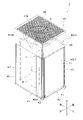
- FIG. 2 is a schematic external perspective view of a heat source unit 2.
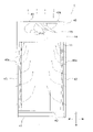
- FIG. 2 is a schematic front view of the heat source unit 2;
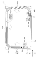
- FIG. 2 is a schematic plan view of the heat source unit 2;
- FIG. 3 is a schematic perspective view of a flow divider 80 and its surroundings, showing a state of attachment to a heat exchange section 50;
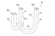
- 3 is a schematic perspective view of a flow dividing pipe 80;
- FIG. FIG. 10 is a cross-sectional view of a branch pipe 80 according to Modification 1 having a third straight portion 82a.
- the heat exchanger of the present disclosure is used, for example, as a heat exchanger for a refrigeration cycle device that uses a vapor compression refrigeration cycle, although its application is not limited.
- a case where the heat exchanger of the present disclosure is used as the heat source side heat exchanger 11 of an air conditioner 1, which is an example of a refrigeration cycle device will be described with reference to the drawings.
- an air conditioner is only an example of a refrigeration cycle device, and the heat exchanger of the present disclosure is used in other refrigeration cycle devices such as refrigerators, freezers, water heaters, floor heating devices, and the like. may
- FIG. 1 is a schematic configuration diagram of an air conditioner 1 having a heat exchanger according to an embodiment of the present disclosure as a heat source side heat exchanger 11.
- FIG. 1 is a schematic configuration diagram of an air conditioner 1 having a heat exchanger according to an embodiment of the present disclosure as a heat source side heat exchanger 11.
- the air conditioner 1 is a device that cools and heats the air-conditioned space by performing a vapor compression refrigeration cycle.
- the air-conditioned space is, for example, a space within a building such as an office building, a commercial facility, or a residence.
- the air conditioner 1 mainly controls the heat source unit 2, the utilization unit 3, the liquid refrigerant communication pipe 4, the gas refrigerant communication pipe 5, and the equipment that constitutes the heat source unit 2 and the utilization unit 3. and a control unit 23 for
- the liquid refrigerant communication pipe 4 and the gas refrigerant communication pipe 5 are refrigerant communication pipes that connect the heat source unit 2 and the utilization unit 3 .
- a refrigerant circuit 6 is configured by connecting the heat source unit 2 and the utilization unit 3 through the refrigerant communication pipes 4 and 5 .
- the air conditioner 1 has one usage unit 3, but the air conditioner 1 has a plurality of usage units 3 connected in parallel to the heat source unit 2 by refrigerant connecting pipes 4 and 5. may have Also, the air conditioner 1 may have a plurality of heat source units 2 . Also, the air conditioner 1 may be an integrated air conditioner in which the heat source unit 2 and the utilization unit 3 are integrally formed.
- the heat source unit 2 mainly includes an accumulator 7, a compressor 8, a flow direction switching mechanism 10, a heat source side heat exchanger 11, an expansion mechanism 12, a liquid side shutoff valve 13, a gas side shutoff valve 14, and a heat source. It has a side fan 15 .
- the usage unit 3 mainly includes a usage side heat exchanger 32 and a usage side fan 33 as shown in FIG.
- the operation of the air conditioner 1 will be outlined.
- the control unit 23 controls the operation of the flow direction switching mechanism 10 to change the state of the refrigerant circuit 6 so that the heat source side heat exchanger 11 functions as a refrigerant radiator (condenser) and the use side heat exchanger 32 is switched to function as a refrigerant evaporator.
- the control unit 23 controls the operation of the flow direction switching mechanism 10 to connect the suction pipe 17 connected to the suction side of the compressor 8 between the flow direction switching mechanism 10 and the gas side shutoff valve 14 . It communicates with the second gas refrigerant pipe 21 .
- control unit 23 controls the operation of the flow direction switching mechanism 10 to connect the discharge pipe 18 connected to the discharge side of the compressor 8 to the flow direction switching mechanism 10 and the gas side of the heat source side heat exchanger 11. (See the solid line in the flow direction switching mechanism 10 in FIG. 1).
- the controller 23 operates the compressor 8 , the heat source side fan 15 and the user side fan 33 .
- the control unit 23 controls the number of rotations of the motors of the compressor 8, the heat source side fan 15, and the user side fan 33, and the electronic expansion valve, which is an example of the expansion mechanism 12, based on the measured values of various sensors. is adjusted to a predetermined opening.
- the low-pressure gas refrigerant in the refrigeration cycle is sucked into the compressor 8 and compressed to a high pressure in the refrigeration cycle, and then discharged from the compressor 8 . be done.
- the high-pressure gas refrigerant discharged from the compressor 8 is sent to the heat source side heat exchanger 11 through the flow direction switching mechanism 10 .
- the high-pressure gas refrigerant sent to the heat source side heat exchanger 11 exchanges heat with air as a cooling source supplied by the heat source side fan 15 in the heat source side heat exchanger 11 functioning as a refrigerant radiator. It dissipates heat and becomes a high-pressure liquid refrigerant.
- the high-pressure liquid refrigerant that has released heat in the heat source side heat exchanger 11 is sent to the expansion mechanism 12 through the liquid refrigerant pipe 20 .
- the high-pressure liquid refrigerant is decompressed to become a low-pressure gas-liquid two-phase refrigerant.
- the low-pressure gas-liquid two-phase refrigerant decompressed by the expansion mechanism 12 is sent to the utilization side heat exchanger 32 through the liquid refrigerant pipe 20 , the liquid side shutoff valve 13 and the liquid refrigerant connecting pipe 4 .
- the low-pressure gas-liquid two-phase refrigerant sent to the user-side heat exchanger 32 is mixed with the air in the air-conditioned space supplied by the user-side fan 33 in the user-side heat exchanger 32 that functions as a refrigerant evaporator. It evaporates through heat exchange. At this time, the air that has been cooled by exchanging heat with the refrigerant is supplied to the air-conditioned space, and the air-conditioned space is cooled.
- the low-pressure gas refrigerant evaporated in the utilization side heat exchanger 32 is sucked into the compressor 8 again through the gas refrigerant communication pipe 5 , the gas side shutoff valve 14 , the flow direction switching mechanism 10 and the accumulator 7 .
- the control unit 23 controls the operation of the flow direction switching mechanism 10 to change the state of the refrigerant circuit 6 so that the heat source side heat exchanger 11 functions as a refrigerant evaporator and the use side heat exchanger 32 functions as a refrigerant evaporator. Switch to a state where it functions as a container (condenser). Specifically, the control unit 23 controls the operation of the flow direction switching mechanism 10 to communicate the suction pipe 17 with the first gas refrigerant pipe 19 and communicate the discharge pipe 18 with the second gas refrigerant pipe 21 (Fig. 1 (see broken line in flow direction switching mechanism 10). During heating operation, the controller 23 operates the compressor 8 , the heat source side fan 15 and the user side fan 33 .
- control unit 23 controls the rotational speeds of the motors of the compressor 8, the heat source side fan 15, and the user side fan 33, and the electronic expansion valve, which is an example of the expansion mechanism 12, based on the measured values of various sensors. is adjusted to a predetermined opening.
- the low-pressure gas refrigerant in the refrigeration cycle is sucked into the compressor 8 and compressed to a high pressure in the refrigeration cycle, and then 8 is discharged.
- the high-pressure gas refrigerant discharged from the compressor 8 is sent to the utilization side heat exchanger 32 through the flow direction switching mechanism 10 , the gas side shutoff valve 14 and the gas refrigerant communication pipe 5 .
- the high-pressure gas refrigerant sent to the user-side heat exchanger 32 is combined with the air and heat in the air-conditioned space supplied by the user-side fan 33 in the user-side heat exchanger 32, which functions as a radiator (condenser) for the refrigerant.
- the heat is exchanged and the heat is released to become a high-pressure liquid refrigerant.
- the air heated by exchanging heat with the refrigerant is supplied to the air-conditioned space, and the air-conditioned space is heated.
- the high-pressure liquid refrigerant that has dissipated heat in the user-side heat exchanger 32 is sent to the expansion mechanism 12 through the liquid-refrigerant communication pipe 4 , the liquid-side shutoff valve 13 , and the liquid-refrigerant pipe 20 .
- the refrigerant sent to the expansion mechanism 12 is depressurized by the expansion mechanism 12 and becomes a low-pressure gas-liquid two-phase refrigerant.
- the low-pressure gas-liquid two-phase refrigerant decompressed by the expansion mechanism 12 is sent to the heat source side heat exchanger 11 through the liquid refrigerant pipe 20 .
- the low-pressure gas-liquid two-phase refrigerant sent to the heat source side heat exchanger 11 is mixed with air as a heat source supplied by the heat source side fan 15 in the heat source side heat exchanger 11 functioning as a refrigerant evaporator. After heat exchange, it evaporates and becomes a low-pressure gas refrigerant.
- the low-pressure refrigerant evaporated in the heat source side heat exchanger 11 is sucked into the compressor 8 again through the flow direction switching mechanism 10 and the accumulator 7 .
- FIG. 2 is a schematic external perspective view of the heat source unit 2.
- FIG. FIG. 3 is a schematic front view of the heat source unit 2 (illustration of refrigerant circuit components other than the heat source side heat exchanger 11 is omitted).
- FIG. 4 is a schematic plan view of the heat source unit 2 (illustration of a fan module 44 to be described later and refrigerant circuit components other than the heat source side heat exchanger 11 is omitted).
- the heat source unit 2 is a top-blown heat exchange unit that draws in air from the sides of the casing 40 and blows air out from the top surface of the casing 40 .
- the heat source unit 2 mainly has a substantially rectangular parallelepiped box-shaped casing 40 and refrigerant circuit components that form part of the refrigerant circuit 6 .
- the refrigerant circuit components include an accumulator 7, a compressor 8, a heat source side heat exchanger 11, a flow direction switching mechanism 10, an expansion mechanism 12, a liquid side stop valve 13, a gas side stop valve 14, and the like.
- the heat source side fan 15 and refrigerant circuit components are housed in the casing 40 .
- the casing 40 mainly includes a pair of mounting legs 41 extending in the left-right direction, a bottom frame 42 spanning over the pair of mounting legs 41, a support 43, a fan module 44, and a side panel 45. and have The struts 43 extend vertically from corners of the bottom frame 42 .
- a fan module 44 is attached to the upper end of the column 43 .
- the side panel 45 is a plate-like member. The side panel 45 is arranged so as to cover the front surface and left side front side of the heat source unit 2 .
- the bottom frame 42 forms the bottom surface of the casing 40.
- the heat source side heat exchanger 11, the compressor 8, the accumulator 7, and the like are arranged on the bottom frame 42.
- the side panel 45 is a plate-shaped member extending vertically from the bottom frame 42 to the fan module 44 .
- the side panel 45 is generally arranged at a position not facing the heat exchange section 50 of the heat source side heat exchanger 11, which will be described later.
- the side panel 45 includes a front panel 45a arranged on the front side and a left side panel 45b arranged on the left side.
- the front panel 45a extends in the left-right direction from near the right end 50R of the heat exchange section 50, which will be described later, to the left front corner of the heat source unit 2.
- the left side panel 45b extends in the front-rear direction from the left front corner of the heat source unit 2 to the vicinity of the left end 50L of the heat exchange section 50.
- the fan module 44 is arranged above the heat source side heat exchanger 11 (above the casing 40).
- the fan module 44 is an assembly in which the heat source side fan 15 is accommodated in a substantially rectangular parallelepiped box having an open upper surface and a lower surface. An opening on the top surface of the fan module 44 is the air outlet 40 b of the casing 40 .
- a blowout grill 46 is provided at the air blowout port 40b.
- the heat source side fan 15 is arranged inside the casing 40 so as to face the air outlet 40b.
- the heat source side fan 15 is a blower that draws air into the casing 40 from an air intake port 40a on the side of the casing 40 and discharges air from an air outlet 40b, as indicated by arrows in FIGS.
- An air intake port 40a for air is formed on the side surface (here, front surface, rear surface, and left and right side surfaces) of the casing 40, and an air outlet 40b for air is formed on the top surface. Due to the airflow generated by the heat source side fan 15 housed in the fan module 44, the air passing through the air intake port 40a flows from the outside to the inside of the casing 40 as indicated by the arrows in FIGS. It is captured.
- the air intake 40a has an air intake 40a1 formed on the front side, an air intake 40a2 formed on the right side, an air intake 40a3 formed on the back, and an air intake 40a3 formed on the left side.
- An air intake 40a4 is included.
- the heat source side heat exchanger 11 is a heat exchanger that exchanges heat between refrigerant and outdoor air.
- the heat source side heat exchanger 11 is a cross fin type fin and tube heat exchanger.
- the heat source side heat exchanger 11 has three heat exchange sections 50 , a plurality of branch pipes 80 and a U-shaped pipe 90 .
- the heat source side heat exchanger 11 is an example of a heat exchanger.
- the heat exchange section 50, the branch pipe 80, and the U-shaped pipe 90 are made of aluminum or an aluminum alloy, and are joined together by brazing or the like.
- the heat source side heat exchanger 11 is formed in a substantially rectangular shape along the side surface of the casing 40 in plan view (see FIG. 4). However, the heat exchange section 50 of the heat source side heat exchanger 11, which will be described later, is not arranged in a portion other than the right side of the front of the heat source unit 2 and on the front left side, and the heat source side heat exchanger 11 is, in plan view, It is formed in a substantially rectangular shape with a part (left front side) missing.
- the heat exchange section 50 has an upwind heat exchange section 50a, a central heat exchange section 50b, and a leeward heat exchange section 50c.
- the windward heat exchange section 50a, the central heat exchange section 50b, and the leeward heat exchange section 50c are collectively referred to as the heat exchange section 50 as well.
- Each heat exchange section 50 is composed of a plurality of heat transfer tubes 52 extending in a predetermined shape on the horizontal plane.
- the windward heat exchange section 50a is composed of a plurality of heat transfer tubes 52a
- the central heat exchange section 50b is composed of a plurality of heat transfer tubes 52b
- the leeward heat exchange section 50c is composed of a plurality of heat transfer tubes. 52c.
- the heat transfer tubes 52a, 52b, and 52c are collectively referred to as the heat transfer tube 52 as well.
- Each heat transfer tube 52 is formed in a shape that draws a substantially rectangular shape in which each side is along the side surface of the casing 40 in plan view, and a portion other than the right front side of the heat source unit 2 and a portion corresponding to the left front side are removed. be done.
- a predetermined number of the heat transfer tubes 52 of each heat exchange section 50 are arranged in a row direction, which is the vertical direction.
- the windward heat exchange section 50a, the central heat exchange section 50b, and the leeward heat exchange section 50c are arranged side by side in the flow direction of the air generated by the heat source side fan 15.
- the air flow direction generated by the heat source side fan 15 means the air flow direction when the heat exchange section 50 is viewed from above (in plan view).
- Each heat exchange section 50 is arranged in the order of the windward heat exchange section 50a, the central heat exchange section 50b, and the leeward side heat exchange section 50c from the windward side in the flow direction of the air generated by the heat source side fan 15.
- the windward heat exchange section 50a is arranged outside the central heat exchange section 50b so as to surround the central heat exchange section 50b.
- the central heat exchange section 50b is arranged outside the leeward heat exchange section 50c so as to surround the leeward heat exchange section 50c in plan view.
- the heat transfer tubes 52 are arranged in multiple stages in the vertical direction (row direction) and arranged in multiple rows (here, three rows) in the air ventilation direction (row direction). ing.
- each heat exchange section 50 By arranging each heat exchange section 50 as described above, when the heat source side fan 15 generates an air flow, the heat exchange amount of the windward heat exchange section 50a is equal to that of the central heat exchange section 50b. The amount of heat exchanged in the central heat exchange section 50b is greater than the amount of heat exchanged in the leeward heat exchange section 50c.
- Each heat transfer tube 52 is supported by a plurality of fins 50d with a predetermined space therebetween in the vertical direction.
- a hole (not shown) for inserting the heat transfer tube 52 is formed in the fin 50d.
- the plurality of fins 50d are orthogonal to the horizontal direction and arranged at predetermined intervals in the extending direction of the heat transfer tubes 52 .
- Each heat transfer tube 52 is supported by the fins 50d by being inserted into holes formed in the fins 50d.
- the heat transfer tubes 52 are arranged vertically so that the central axes of the heat transfer tubes 52 of the heat exchange sections 50 do not overlap each other when viewed from the horizontal direction, in order to effectively perform heat exchange between the refrigerant and the outdoor air. be. Note that FIG. 4 shows only a portion of the plurality of fins 50d for convenience.
- the heat exchange unit 50 is provided with pipes at the right end 50R and the left end 50L for causing the refrigerant that has flowed into the heat transfer pipe 52 to meander and flow vertically.
- the right end 50R of the heat exchange portion 50 is an end located on the front right side of the heat source unit 2 in plan view.
- 50 L of left ends of the heat exchange part 50 are edge parts located in front of the left surface of the heat-source unit 2 in planar view.
- a plurality of U-shaped tubes 90 are provided at the right end portion 52R, which is the end portion of the heat transfer tube 52 positioned at the right end 50R.
- a plurality of branch pipes 80 are provided at the left end portion 52L, which is the end portion of the heat transfer tube 52 located at the left end 50L.
- the U-tube 90 is a pipe that connects the right end 52bR of the heat transfer tube 52b and the right end 52cR of the heat transfer tube 52c in a predetermined stage, and the right end 50aR of the heat transfer tube 52a in the upper stage. .
- the refrigerant flowing out from the right end portion 52bR of the heat transfer tube 52b and the right end portion 52cR of the heat transfer tube 52c of a predetermined stage flows through the U-shaped tube 90 to the stage one stage above. flow into the windward heat exchange section 50a.
- the branch pipe 80 is a pipe that connects the left end 52aL of the heat transfer tube 52a in a given stage, the left end 52bL of the heat transfer tube 52b in the same stage, and the left end 52cL of the heat transfer tube 52c. Details of the flow dividing pipe 80 will be described later.
- the heat transfer tube 52a that constitutes the windward heat exchange section 50a is an example of a third heat transfer tube.
- the heat transfer tubes 52b forming the central heat exchange section 50b are an example of first heat transfer tubes.
- the heat transfer tube 52c forming the leeward heat exchange section 50c is an example of a second heat transfer tube.
- the flow division pipe 80 divides the refrigerant flowing out of the heat transfer pipe 52a of the windward heat exchange section 50a to transfer the refrigerant to the heat transfer pipe 52b of the central heat exchange section 50b and the leeward heat exchange section 50c. It is a pipe for flowing into the heat pipe 52c.
- the branch pipe 80 is a branch pipe having three ends, a first end 80a, a second end 80b, and a third end 80c, which are connected to each other.
- FIG. 5 is a schematic perspective view of the flow dividing pipe 80 and its surroundings, showing the state of attachment to the heat exchange section 50.
- FIG. FIG. 6 is a schematic perspective view of the flow dividing tube 80. As shown in FIG.
- the branch pipe 80 has a U-shaped portion 81 and an inflow portion 82 .
- the U-shaped portion 81 and the inflow portion 82 are pipes having the same inner diameter and different shapes.
- the U-shaped portion 81 splits the refrigerant that has flowed in from the inflow portion 82 into two and flows them into the heat transfer tubes 52b and 52c.
- the U-shaped portion 81 is composed of a bent portion 81a, a first straight portion 81b, and a second straight portion 81c.
- the bent portion 81a is a portion bent with a predetermined radius.
- the first straight portion 81b is a portion linearly extending a predetermined length from one end of the bent portion 81a.
- the second straight portion 81c is a portion extending linearly for a predetermined length from the other end of the bent portion 81a.
- the first end 80a is the end of the first linear portion 81b opposite to the bent portion 81a.
- the second end 80b is the end of the second linear portion 81c opposite to the bent portion 81a.
- the inflow portion 82 causes the refrigerant that has flowed out from the heat transfer tubes 52 a of the windward heat exchange portion 50 a to flow into the U-shaped portion 81 .
- One end of the inflow portion 82 is connected to the first linear portion 81b.
- the third end 80c is the end of the inflow portion 82 opposite to the first linear portion 81b.
- the channels through which the coolant flows in the branch pipe 80 include the first channel C1 and the second channel C2.
- the first flow path C1 is a flow path that connects the first end portion 80a and the third end portion 80c and includes the inflow portion 82 and part of the first straight portion 81b therebetween.
- the first flow path C1 is indicated by a two-dot chain line in FIG.
- the second flow path C2 is a flow path connecting the second end 80b and the third end 80c and including the inflow portion 82, part of the bent portion 81a, and the second straight portion 81c therebetween.
- the second flow path C2 is indicated by dashed lines in FIG.
- the flow dividing pipe 80 is formed such that the length of the first flow path C1 is shorter than that of the second flow path C2.
- the ratio of the length of the first flow path C1 and the length of the second flow path C2 of the flow dividing tube 80 is the ratio of the heat exchange amount of the heat transfer tube 52b to which the flow dividing tube 80 is connected to the heat transfer amount of the heat transfer tube 52c.
- the ratio between the length of the first flow path C1 and the length of the second flow path C2 is the same as the ratio between the heat exchange amount of the heat transfer tube 52b to which the branch tube 80 is connected and the heat transfer amount of the heat transfer tube 52c.
- the flow dividing tube 80 connects the left end 52aL of the heat transfer tube 52a with the left end 52bL of the heat transfer tube 52b and the left end 52cL2 of the heat transfer tube 52c arranged in the same stage. More specifically, the first end 80a of the flow dividing tube 80 is connected to the left end 52bL of the heat transfer tube 52b. Also, the second end 80b of the flow dividing tube 80 is connected to the left end 52cL of the heat transfer tube 52c. Furthermore, the third end 80c of the flow dividing tube 80 is connected to the left end 52aL of the heat transfer tube 52a.
- gas-liquid two-phase refrigerant flows from the liquid refrigerant pipe 20 into the lowermost heat transfer pipe 52 .
- the heat transfer tube into which the refrigerant flows may be either the heat transfer tube 52b of the central heat exchange section 50b or the heat transfer tube 52c of the leeward heat exchange section 50c.
- the refrigerant that has flowed into the heat transfer tube 52 from the left end 52L flows through the heat transfer tube 52 to the right end 52R side, and then passes through the U-shaped tube 90 to the windward heat exchange located one stage above.
- the refrigerant that has flowed into the branch pipe 80 passes through the inflow portion 82 and then flows into the U-shaped portion 81 to be branched.
- the refrigerant flowing into the branch pipe 80 is divided into the refrigerant flowing through the first flow path C1 and the refrigerant flowing through the second flow path C2.
- the coolant flowing through the first flow path C1 passes through the inflow portion 82, flows into the first straight portion 81b, and flows out from the first end portion 80a.
- the refrigerant that has flowed out from the first end portion 80a flows into the heat transfer tubes 52b of the central heat exchange portion 50b.
- the coolant flowing through the second flow path C2 passes through the inflow portion 82 and flows into the bent portion 81a, then passes through the second straight portion 81c and flows out from the second end portion 80b.
- the refrigerant that has flowed out from the second end portion 80b flows into the heat transfer tubes 52c of the leeward heat exchange portion 50c.
- the refrigerant flowing from the heat transfer tube 52a into the branch tube 80 flows through the branch tube 80 and then into the heat transfer tubes 52b and 52c in the same stage as the heat transfer tube 52a.
- the refrigerant that has flowed into the heat transfer tubes 52b and 52c flows toward the right end portions 50bR and 50cR, passes through the U-shaped tube 90, and flows into the heat transfer tube 52a one stage above.
- the refrigerant that has flowed into the heat transfer tube 52a flows through the heat transfer tube 52a to the left end 50aL, then flows into the flow dividing tube 80 connected to the left end 52aL, and again flows into the heat transfer tube 52b in the same stage as the heat transfer tube 52a. 52c.
- the refrigerant that has flowed into the heat exchange section 50 from the liquid refrigerant pipe 20 flows upward while meandering inside the heat transfer pipe 52 . After that, the refrigerant flows out from the heat transfer pipes 52 a of a predetermined stage, flows outside the heat source side heat exchanger 11 , and flows into the first gas refrigerant pipes 19 .
- the heat source side heat exchanger 11 of the present disclosure includes a central heat exchange section 50b (first heat transfer tube), a leeward side heat exchange section 50c (second heat transfer tube), and a flow dividing tube 80.
- the branch pipe 80 has a first end 80a connected to the end of the central heat exchange section 50b, a second end 80b connected to the end of the leeward heat exchange section 50c, and a third end 80c. have.
- a flow dividing tube 80 connects a first end 80a, a second end 80b, and a third end 80c to each other.
- the amount of heat exchanged in the central heat exchange section 50b is greater than the amount of heat exchanged in the leeward heat exchange section 50c.
- the length of the first flow path C1 connecting the first end 80a and the third end 80c is longer than the length of the second flow path C2 connecting the second end 80b and the third end 80c. short.
- the length of the first flow path C1 is shorter than that of the second flow path C2. It is small compared to the pressure loss received. Therefore, the flow rate of the refrigerant flowing through the flow dividing pipe 80 into the heat transfer pipe 52b is greater than that of the refrigerant flowing through the flow dividing pipe 80 into the heat transfer pipe 52c.
- the heat source side heat exchanger 11 it is possible to improve the capacity while suppressing the increase in manufacturing cost by using the branch pipe 80 having a simple structure.
- the ratio between the length of the first flow path C1 and the length of the second flow path C2 of the flow dividing tube 80 is the amount of heat exchanged in the heat transfer tube 52b to which the flow dividing tube 80 is connected. It may be formed so as to correspond to the ratio with the heat exchange amount of 52c.
- the amount of refrigerant flowing out from the first end portion 80a and the amount of refrigerant flowing out from the second end portion 80b depend on the pressure received by the refrigerant in the first flow path C1. It is determined by the loss and the pressure loss received by the refrigerant in the second flow path C2. Therefore, the ratio between the amount of refrigerant flowing into the heat transfer tube 52b and the amount of refrigerant flowing into the heat transfer tube 52c is determined by the ratio between the length of the first flow path C1 and the length of the second flow path C2. .
- the ratio of the length of the first flow path C1 to the length of the second flow path C2 is the ratio of the heat exchange amount of the heat transfer tube 52b to which the branch tube 80 is connected to the heat exchange amount of the heat transfer tube 52c.
- the difference in degree of superheat between the heat transfer tube 52b and the heat transfer tube 5250c can be reduced by the branch tube 80, and the heat source side heat exchanger 11 with higher capacity can be provided.
- the branch pipe 80 has a U-shaped portion 81 and an inflow portion 82 having one end connected to the U-shaped portion 81 .
- the U-shaped portion 81 has a bent portion 81a, a first straight portion 81b and a second straight portion 81c.
- the bent portion 81a is bent with a predetermined radius.
- the first linear portion 81b extends linearly from one end of the bent portion 81a.
- the second linear portion 81c extends linearly from the other end of the bent portion 81a.
- the end portion of the first linear portion 81b opposite to the bent portion 81a is the first end portion 80a.
- the end portion of the second linear portion 81c opposite to the bent portion 81a is the second end portion 80b.
- One end of the inflow portion 82 is connected to the first linear portion 81b, and the other end is the third end portion 80c.
- the first flow path C1 includes an inflow portion 82 and part of the first linear portion 81b.
- the second flow path C2 includes an inflow portion 82, a portion of the bent portion 81a, and a second straight portion 81c.
- the branch pipe 80 since the branch pipe 80 has a simple structure consisting of the U-shaped portion 81 and the inflow portion 82, it can be manufactured at low cost. Also, the lengths of the first flow path C1 and the second flow path C2 can be easily adjusted by changing the attachment position of the inflow portion 82 to the U-shaped portion 81 .
- the inflow portion 82 may have a third linear portion 82a linearly extending from a portion connected to the first linear portion 81b.
- FIG. 7 is a cross-sectional view of a branch pipe 80 according to Modification 1 having a third straight portion 82a.
- FIG. 7 is a cross-sectional view of the branch pipe 80 according to Modification 1 taken along a plane including the first straight portion 81b and the third straight portion 82a.
- the angle ⁇ is preferably 90° or more and 135° or less.
- the coolant passing through the first flow path C1 smoothly flows from the inflow portion 82 into the first linear portion 81b, compared to when the angle ⁇ is smaller than 90°. Therefore, a large flow rate of the refrigerant flowing into the heat transfer tubes 52b is ensured, and the heat source side heat exchanger 11 with higher capacity can be provided.
- the third end portion 80c may be connected to the first gas refrigerant pipe 19 or the liquid refrigerant pipe 20, and the first end portion 80a and the second end portion 80b may be connected to the heat transfer pipes 52 having different heat exchange amounts.
- the flow rate of the refrigerant flowing into the two heat transfer tubes 52 through the first gas refrigerant pipe 19 or the liquid refrigerant pipe 20 can be made different from each other by the flow dividing pipe 80 , whereby the two heat transfer pipes 52 It is possible to suppress the deterioration of the performance of the heat exchange section 50 due to the difference in the amount of heat exchanged between.
Landscapes
- Engineering & Computer Science (AREA)
- Physics & Mathematics (AREA)
- Thermal Sciences (AREA)
- Mechanical Engineering (AREA)
- General Engineering & Computer Science (AREA)
- Heat-Exchange Devices With Radiators And Conduit Assemblies (AREA)
Priority Applications (4)
| Application Number | Priority Date | Filing Date | Title |
|---|---|---|---|
| CN202280011007.6A CN116724209B (zh) | 2021-01-22 | 2022-01-21 | 热交换器 |
| ES22742693T ES3039562T3 (en) | 2021-01-22 | 2022-01-21 | Heat exchanger |
| EP22742693.9A EP4283221B1 (en) | 2021-01-22 | 2022-01-21 | Heat exchanger |
| US18/222,599 US11994352B2 (en) | 2021-01-22 | 2023-07-17 | Heat exchanger |
Applications Claiming Priority (2)
| Application Number | Priority Date | Filing Date | Title |
|---|---|---|---|
| JP2021-008709 | 2021-01-22 | ||
| JP2021008709A JP7137092B2 (ja) | 2021-01-22 | 2021-01-22 | 熱交換器 |
Related Child Applications (1)
| Application Number | Title | Priority Date | Filing Date |
|---|---|---|---|
| US18/222,599 Continuation US11994352B2 (en) | 2021-01-22 | 2023-07-17 | Heat exchanger |
Publications (1)
| Publication Number | Publication Date |
|---|---|
| WO2022158574A1 true WO2022158574A1 (ja) | 2022-07-28 |
Family
ID=82548807
Family Applications (1)
| Application Number | Title | Priority Date | Filing Date |
|---|---|---|---|
| PCT/JP2022/002237 Ceased WO2022158574A1 (ja) | 2021-01-22 | 2022-01-21 | 熱交換器 |
Country Status (6)
| Country | Link |
|---|---|
| US (1) | US11994352B2 (es) |
| EP (1) | EP4283221B1 (es) |
| JP (1) | JP7137092B2 (es) |
| CN (1) | CN116724209B (es) |
| ES (1) | ES3039562T3 (es) |
| WO (1) | WO2022158574A1 (es) |
Families Citing this family (1)
| Publication number | Priority date | Publication date | Assignee | Title |
|---|---|---|---|---|
| CN115682472B (zh) * | 2022-11-01 | 2024-09-24 | 浙江宝丰科技股份有限公司 | 一种蒸发式冷凝器 |
Citations (8)
| Publication number | Priority date | Publication date | Assignee | Title |
|---|---|---|---|---|
| JPH01234689A (ja) * | 1988-03-11 | 1989-09-19 | Matsushita Refrig Co Ltd | 三方ベンド |
| JPH01305276A (ja) | 1988-05-31 | 1989-12-08 | Matsushita Seiko Co Ltd | 空気調和機の冷媒分岐装置 |
| JPH06194003A (ja) * | 1992-12-25 | 1994-07-15 | Hitachi Ltd | 空気調和機 |
| JPH074882A (ja) * | 1993-06-11 | 1995-01-10 | Hitachi Ltd | 熱交換器 |
| JP2007046804A (ja) * | 2005-08-08 | 2007-02-22 | Mitsubishi Electric Corp | 空気調和機及び空気調和機の製造方法 |
| WO2014115240A1 (ja) * | 2013-01-22 | 2014-07-31 | 三菱電機株式会社 | 冷媒分配器及びこの冷媒分配器を用いたヒートポンプ装置 |
| WO2015111220A1 (ja) * | 2014-01-27 | 2015-07-30 | 三菱電機株式会社 | 熱交換器、及び、空気調和装置 |
| JP2019132511A (ja) * | 2018-01-31 | 2019-08-08 | ダイキン工業株式会社 | 冷凍装置 |
Family Cites Families (9)
| Publication number | Priority date | Publication date | Assignee | Title |
|---|---|---|---|---|
| JP3204546B2 (ja) * | 1992-08-31 | 2001-09-04 | 東芝キヤリア株式会社 | 熱交換器 |
| JPH0875316A (ja) * | 1994-08-31 | 1996-03-19 | Toyo Radiator Co Ltd | 空調用熱交換器の分流管構造 |
| US6142220A (en) * | 1996-10-02 | 2000-11-07 | Matsushita Electric Industrial Co., Ltd. | Finned heat exchanger |
| US5896921A (en) * | 1997-05-27 | 1999-04-27 | Daewoo Electronics Co., Ltd. | Indoor unit of an air conditioner |
| WO1999063285A1 (en) * | 1998-05-29 | 1999-12-09 | Daikin Industries, Ltd. | Flow merging and dividing device and heat exchanger using the device |
| JP2006097987A (ja) | 2004-09-29 | 2006-04-13 | Daikin Ind Ltd | 三方分岐管及びこれを用いたフィンチューブ型熱交換器 |
| JP4922669B2 (ja) * | 2006-06-09 | 2012-04-25 | 日立アプライアンス株式会社 | 空気調和機及び空気調和機の熱交換器 |
| US10907902B2 (en) * | 2015-09-10 | 2021-02-02 | Hitachi-Johnson Controls Air Conditioning, Inc. | Heat exchanger |
| US11112149B2 (en) * | 2017-03-09 | 2021-09-07 | Mitsubishi Electric Corporation | Heat exchanger and air-conditioning apparatus |
-
2021
- 2021-01-22 JP JP2021008709A patent/JP7137092B2/ja active Active
-
2022
- 2022-01-21 ES ES22742693T patent/ES3039562T3/es active Active
- 2022-01-21 EP EP22742693.9A patent/EP4283221B1/en active Active
- 2022-01-21 WO PCT/JP2022/002237 patent/WO2022158574A1/ja not_active Ceased
- 2022-01-21 CN CN202280011007.6A patent/CN116724209B/zh active Active
-
2023
- 2023-07-17 US US18/222,599 patent/US11994352B2/en active Active
Patent Citations (8)
| Publication number | Priority date | Publication date | Assignee | Title |
|---|---|---|---|---|
| JPH01234689A (ja) * | 1988-03-11 | 1989-09-19 | Matsushita Refrig Co Ltd | 三方ベンド |
| JPH01305276A (ja) | 1988-05-31 | 1989-12-08 | Matsushita Seiko Co Ltd | 空気調和機の冷媒分岐装置 |
| JPH06194003A (ja) * | 1992-12-25 | 1994-07-15 | Hitachi Ltd | 空気調和機 |
| JPH074882A (ja) * | 1993-06-11 | 1995-01-10 | Hitachi Ltd | 熱交換器 |
| JP2007046804A (ja) * | 2005-08-08 | 2007-02-22 | Mitsubishi Electric Corp | 空気調和機及び空気調和機の製造方法 |
| WO2014115240A1 (ja) * | 2013-01-22 | 2014-07-31 | 三菱電機株式会社 | 冷媒分配器及びこの冷媒分配器を用いたヒートポンプ装置 |
| WO2015111220A1 (ja) * | 2014-01-27 | 2015-07-30 | 三菱電機株式会社 | 熱交換器、及び、空気調和装置 |
| JP2019132511A (ja) * | 2018-01-31 | 2019-08-08 | ダイキン工業株式会社 | 冷凍装置 |
Non-Patent Citations (1)
| Title |
|---|
| See also references of EP4283221A4 |
Also Published As
| Publication number | Publication date |
|---|---|
| US20230400265A1 (en) | 2023-12-14 |
| ES3039562T3 (en) | 2025-10-22 |
| EP4283221A4 (en) | 2024-07-17 |
| JP2022112775A (ja) | 2022-08-03 |
| US11994352B2 (en) | 2024-05-28 |
| CN116724209A (zh) | 2023-09-08 |
| EP4283221A1 (en) | 2023-11-29 |
| CN116724209B (zh) | 2024-01-30 |
| EP4283221B1 (en) | 2025-07-30 |
| JP7137092B2 (ja) | 2022-09-14 |
Similar Documents
| Publication | Publication Date | Title |
|---|---|---|
| US11747059B2 (en) | Heat exchanger | |
| JP5423792B2 (ja) | 天井設置型空気調和装置 | |
| US8205470B2 (en) | Indoor unit for air conditioner | |
| JP5447569B2 (ja) | 空気調和装置の熱交換器及び空気調和装置 | |
| US11499762B2 (en) | Heat exchanger and air conditioner | |
| WO2013160957A1 (ja) | 熱交換器、室内機及び冷凍サイクル装置 | |
| US20210041115A1 (en) | Indoor heat exchanger and air conditioning apparatus | |
| JP5354004B2 (ja) | 空気調和装置 | |
| CN110300876A (zh) | 热交换单元 | |
| JP2019011923A (ja) | 熱交換器 | |
| JP6332377B2 (ja) | 熱交換器 | |
| JP7137092B2 (ja) | 熱交換器 | |
| US12078427B2 (en) | Heat exchanger and air conditioner having the same | |
| CN110382978A (zh) | 热交换器以及空调机 | |
| WO2018025325A1 (ja) | 室外ユニット、空気調和装置、及び、室外ユニットの取っ手の製造方法 | |
| JP6661781B2 (ja) | 冷凍サイクル装置 | |
| JP7011187B2 (ja) | 冷媒分流器、及び、空気調和機 | |
| JP6486718B2 (ja) | 熱交換器 | |
| WO2021234960A1 (ja) | 空気調和機の室外機 | |
| JPWO2019155571A1 (ja) | 熱交換器および冷凍サイクル装置 | |
| JP2015175539A (ja) | 熱交換器 |
Legal Events
| Date | Code | Title | Description |
|---|---|---|---|
| 121 | Ep: the epo has been informed by wipo that ep was designated in this application |
Ref document number: 22742693 Country of ref document: EP Kind code of ref document: A1 |
|
| WWE | Wipo information: entry into national phase |
Ref document number: 202280011007.6 Country of ref document: CN |
|
| NENP | Non-entry into the national phase |
Ref country code: DE |
|
| ENP | Entry into the national phase |
Ref document number: 2022742693 Country of ref document: EP Effective date: 20230822 |
|
| WWG | Wipo information: grant in national office |
Ref document number: 2022742693 Country of ref document: EP |