WO2022162902A1 - Terminal et procédé de communication sans fil - Google Patents
Terminal et procédé de communication sans fil Download PDFInfo
- Publication number
- WO2022162902A1 WO2022162902A1 PCT/JP2021/003359 JP2021003359W WO2022162902A1 WO 2022162902 A1 WO2022162902 A1 WO 2022162902A1 JP 2021003359 W JP2021003359 W JP 2021003359W WO 2022162902 A1 WO2022162902 A1 WO 2022162902A1
- Authority
- WO
- WIPO (PCT)
- Prior art keywords
- pucch
- dmrs
- information
- reference signal
- transmission
- Prior art date
- Legal status (The legal status is an assumption and is not a legal conclusion. Google has not performed a legal analysis and makes no representation as to the accuracy of the status listed.)
- Ceased
Links
Images












Classifications
-
- H—ELECTRICITY
- H04—ELECTRIC COMMUNICATION TECHNIQUE
- H04W—WIRELESS COMMUNICATION NETWORKS
- H04W72/00—Local resource management
- H04W72/04—Wireless resource allocation
Definitions
- FIG. 1 is an overall schematic configuration diagram of a radio communication system 10 according to the present embodiment.
- Radio communication system 10 is, for example, a radio communication system according to 5G New Radio (NR), Next Generation-Radio Access Network 20 (hereinafter, NG-RAN 20, and terminal 200 (User Equipment 200, hereinafter, UE 200).
- NR 5G New Radio
- NG-RAN 20 Next Generation-Radio Access Network 20
- UE 200 User Equipment 200
- NG-RAN 20 includes a radio base station 100 (hereinafter gNB 100).
- gNB 100 radio base station 100
- the specific configuration of the radio communication system 10 including the number of gNBs and UEs is not limited to the example shown in FIG.
- the above-mentioned Massive MIMO is a MIMO (Multiple-Input Multiple-Output) transmission system that spatially multiplexes and transmits radio signals by using multiple antennas for transmission and reception, and uses more antennas. It can be interpreted as a technology that realizes the formation of a sharp radio wave beam that enables radio wave propagation loss compensation when using a high frequency band and the simultaneous transmission of more streams by adopting a super multi-element antenna composed of elements. .
- MIMO Multiple-Input Multiple-Output
- PUCCH Format (hereinafter referred to as PF) 1, 3, 4 is called a long format and has 4 to 14 symbols.
- PF 0, 2 is called a short format and has 1 or 2 symbols.
- the PUCCH may be called an uplink control channel and may be used to transmit control signals in the uplink (UL).
- PUCCH may be used to transmit uplink control information (UCI).
- UCI uplink control information
- the UCI may include at least one of Hybrid automatic repeat request (HARQ) ACK/NACK, scheduling request (SR) from UE 200, and Channel State Information (CSI).
- HARQ Hybrid automatic repeat request
- SR scheduling request
- CSI Channel State Information
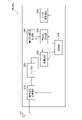
- the radio signal transmitting/receiving unit 210 transmits/receives radio signals according to NR.
- the radio signal transmitting/receiving unit 210 controls radio (RF) signals transmitted from multiple antenna elements to generate beams with higher directivity. It can support aggregation (CA), dual connectivity (DC) in which communication is performed simultaneously between the UE and two NG-RAN Nodes, and the like.
- CA aggregation
- DC dual connectivity
- DMRS for PUCCH may be interpreted as DMRS for supporting MIMO transmission on PUCCH.
- the DMRS may have orthogonality.
- the DMRSs may be orthogonal in at least one of the time domain and frequency domain.
- Such DMRS may be referred to as orthogonal DMRS.
- the encoding/decoding unit 250 performs data segmentation/concatenation, channel coding/decoding, etc. for each predetermined communication destination (gNB 100 or other gNB).
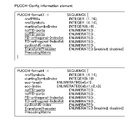
- the control unit 270 may configure PUCCH using at least one of precoding information for PUCCH and precoding information for PUSCH.
- the precoding information may be a Precoding table (Precoding matrix) or a TPMI table (Precoding information and number of layers). An example of setting PUCCH using the precoding information will be described later.
- Operation example 1 DMRS for PUCCH (3.3.1.1)
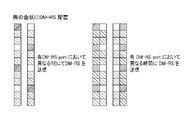
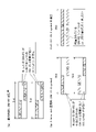
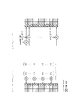
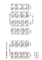
- Arrangement of Orthogonal DMRS are arranged to realize PUCCHMIMO transmission.
- multiple orthogonal DMRSs may be arranged by any of the following methods.
- the DMRS of PF 2 may be multiplied by the TD-OCC pattern or FD-OCC pattern to give orthogonality.
- the orthogonality may be ensured by any one of the following methods or a combination of both.
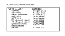
- a precoding matrix may be selected without notifying Maxrank (Opt. 2). In this case, it may operate according to any of the following.
- ⁇ (Alt.2): Spatial relation group configured by multiple Spatial relation is added to PUCCH-Config Spatial relation info in Spatial relation group Set ID and may be selected in the same way as Spatial relation info. Also, a precoding matrix to be used may be set in the spatial relation group by a similar method.
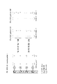
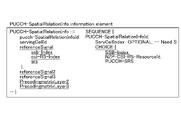
- FIG. 26 shows a configuration example of the PUCCH-SpatialRelationInfo information element according to Operation Example 4.
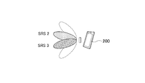
- a plurality of reference signals (which may include synchronization signal blocks (SSB)) may be set in one spatial relation info. In this case, if the number of MIMO layers is 2, only reference signal 1 and reference signal 2 may be used.
- SSB synchronization signal blocks
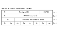
- multiple DMRS ports used for PUCCH MIMO transmission may be specified.
- the UE 200 may perform the following processing.
- Alt.1 Refer to the DCI of the same (or immediately before/after) slot DCI that allocates PDSCH resource allocation linked to PUCCH (for HARQ feedback)
- Alt.2 Refer to the DCI of the same (or immediately before/after) slot as the PUCCH to be transmitted (for CSI report/HARQ feedback)
- Alt.3 Refer to PUSCH in the same (or immediately before/after) slot as PUCCH to be transmitted (for CSI report/HARQ feedback)
- the information of the slot to be referred to may be specified by higher layer or lower layer signaling (DCI).
- the communication device 1004 includes a high-frequency switch, duplexer, filter, frequency synthesizer, etc., for realizing at least one of frequency division duplex (FDD) and time division duplex (TDD).
- FDD frequency division duplex
- TDD time division duplex
- one subframe may be called a transmission time interval (TTI)
- TTI transmission time interval
- multiple consecutive subframes may be called a TTI
- one slot or one minislot may be called a TTI. That is, at least one of the subframe and TTI may be a subframe (1ms) in existing LTE, may be a period shorter than 1ms (eg, 1-13 symbols), or a period longer than 1ms may be Note that the unit representing the TTI may be called a slot, minislot, or the like instead of a subframe.
- the time domain of an RB may include one or more symbols and may be 1 slot, 1 minislot, 1 subframe, or 1 TTI long.
- One TTI, one subframe, etc. may each consist of one or more resource blocks.
- Radio communication system 20 NG-RAN 100 gNB 200UE 210 radio signal transmission/reception unit 220 amplifier unit 230 modulation/demodulation unit 240 control signal/reference signal processing unit 250 encoding/decoding unit 260 data transmission/reception unit 270 control unit 1001 processor 1002 memory 1003 storage 1004 communication device 1005 input device 1006 output device 1007 bus
Landscapes
- Engineering & Computer Science (AREA)
- Computer Networks & Wireless Communication (AREA)
- Signal Processing (AREA)
- Mobile Radio Communication Systems (AREA)
Abstract
Ce terminal comprend une unité d'émission qui émet un signal de référence de démodulation pour un canal de commande de liaison montante, et une unité de commande qui commande l'émission du signal de référence de démodulation. L'unité de commande règle le signal de référence de démodulation afin qu'il soit orthogonal à une région temporelle et/ou à une région de fréquence.
Priority Applications (2)
| Application Number | Priority Date | Filing Date | Title |
|---|---|---|---|
| CN202180090275.7A CN116746252A (zh) | 2021-01-29 | 2021-01-29 | 终端及无线通信方法 |
| PCT/JP2021/003359 WO2022162902A1 (fr) | 2021-01-29 | 2021-01-29 | Terminal et procédé de communication sans fil |
Applications Claiming Priority (1)
| Application Number | Priority Date | Filing Date | Title |
|---|---|---|---|
| PCT/JP2021/003359 WO2022162902A1 (fr) | 2021-01-29 | 2021-01-29 | Terminal et procédé de communication sans fil |
Publications (1)
| Publication Number | Publication Date |
|---|---|
| WO2022162902A1 true WO2022162902A1 (fr) | 2022-08-04 |
Family
ID=82654381
Family Applications (1)
| Application Number | Title | Priority Date | Filing Date |
|---|---|---|---|
| PCT/JP2021/003359 Ceased WO2022162902A1 (fr) | 2021-01-29 | 2021-01-29 | Terminal et procédé de communication sans fil |
Country Status (2)
| Country | Link |
|---|---|
| CN (1) | CN116746252A (fr) |
| WO (1) | WO2022162902A1 (fr) |
Citations (2)
| Publication number | Priority date | Publication date | Assignee | Title |
|---|---|---|---|---|
| WO2019030894A1 (fr) * | 2017-08-10 | 2019-02-14 | 三菱電機株式会社 | Dispositif de transmission |
| WO2019239600A1 (fr) * | 2018-06-15 | 2019-12-19 | 株式会社Nttドコモ | Terminal utilisateur et procédé de communication sans fil |
-
2021
- 2021-01-29 CN CN202180090275.7A patent/CN116746252A/zh active Pending
- 2021-01-29 WO PCT/JP2021/003359 patent/WO2022162902A1/fr not_active Ceased
Patent Citations (2)
| Publication number | Priority date | Publication date | Assignee | Title |
|---|---|---|---|---|
| WO2019030894A1 (fr) * | 2017-08-10 | 2019-02-14 | 三菱電機株式会社 | Dispositif de transmission |
| WO2019239600A1 (fr) * | 2018-06-15 | 2019-12-19 | 株式会社Nttドコモ | Terminal utilisateur et procédé de communication sans fil |
Also Published As
| Publication number | Publication date |
|---|---|
| CN116746252A (zh) | 2023-09-12 |
Similar Documents
| Publication | Publication Date | Title |
|---|---|---|
| JP7499384B2 (ja) | 端末 | |
| WO2022079876A1 (fr) | Terminal | |
| WO2022149270A1 (fr) | Terminal, station de base et procédé de communication radio | |
| WO2020261463A1 (fr) | Terminal | |
| WO2022201401A1 (fr) | Terminal et station de base radio | |
| WO2021171594A1 (fr) | Terminal | |
| WO2022244496A1 (fr) | Terminal, système de communication sans fil et procédé de communication sans fil | |
| WO2021009919A1 (fr) | Terminal | |
| WO2022244501A1 (fr) | Terminal et procédé de communication sans fil | |
| WO2023053393A1 (fr) | Terminal et procédé de communication sans fil | |
| JP7699199B2 (ja) | 端末、基地局、無線通信システム及び無線通信方法 | |
| JP7528197B2 (ja) | 端末 | |
| JP7719079B2 (ja) | 端末、基地局、無線通信システム及び無線通信方法 | |
| WO2022201462A1 (fr) | Terminal, système de communication sans fil et procédé de communication sans fil | |
| WO2022201403A1 (fr) | Terminal et procédé de communication sans fil | |
| WO2022074842A1 (fr) | Terminal | |
| WO2022162906A1 (fr) | Terminal et procédé de communication sans fil | |
| JP7758733B2 (ja) | 端末、無線通信システム及び無線通信方法 | |
| JP7842270B2 (ja) | 端末 | |
| JP7682992B2 (ja) | 端末、基地局、無線通信システム及び無線通信方法 | |
| WO2022244504A1 (fr) | Terminal, système de communication sans fil et procédé de communication sans fil | |
| CN116746252A (zh) | 终端及无线通信方法 | |
| JP2025081600A (ja) | 端末 | |
| WO2022249721A1 (fr) | Terminal, système de communication sans fil, et procédé de communication sans fil | |
| WO2023026968A1 (fr) | Terminal, système de communication sans fil et procédé de communication sans fil |
Legal Events
| Date | Code | Title | Description |
|---|---|---|---|
| 121 | Ep: the epo has been informed by wipo that ep was designated in this application |
Ref document number: 21922917 Country of ref document: EP Kind code of ref document: A1 |
|
| WWE | Wipo information: entry into national phase |
Ref document number: 202180090275.7 Country of ref document: CN |
|
| NENP | Non-entry into the national phase |
Ref country code: DE |
|
| 122 | Ep: pct application non-entry in european phase |
Ref document number: 21922917 Country of ref document: EP Kind code of ref document: A1 |
|
| NENP | Non-entry into the national phase |
Ref country code: JP |