WO2022163554A1 - マイクロ波処理装置 - Google Patents
マイクロ波処理装置 Download PDFInfo
- Publication number
- WO2022163554A1 WO2022163554A1 PCT/JP2022/002317 JP2022002317W WO2022163554A1 WO 2022163554 A1 WO2022163554 A1 WO 2022163554A1 JP 2022002317 W JP2022002317 W JP 2022002317W WO 2022163554 A1 WO2022163554 A1 WO 2022163554A1
- Authority
- WO
- WIPO (PCT)
- Prior art keywords
- heated
- microwave
- control unit
- unit
- heating
- Prior art date
- Legal status (The legal status is an assumption and is not a legal conclusion. Google has not performed a legal analysis and makes no representation as to the accuracy of the status listed.)
- Ceased
Links
Images










Classifications
-
- H—ELECTRICITY
- H05—ELECTRIC TECHNIQUES NOT OTHERWISE PROVIDED FOR
- H05B—ELECTRIC HEATING; ELECTRIC LIGHT SOURCES NOT OTHERWISE PROVIDED FOR; CIRCUIT ARRANGEMENTS FOR ELECTRIC LIGHT SOURCES, IN GENERAL
- H05B6/00—Heating by electric, magnetic or electromagnetic fields
- H05B6/64—Heating using microwaves
- H05B6/6447—Method of operation or details of the microwave heating apparatus related to the use of detectors or sensors
-
- H—ELECTRICITY
- H05—ELECTRIC TECHNIQUES NOT OTHERWISE PROVIDED FOR
- H05B—ELECTRIC HEATING; ELECTRIC LIGHT SOURCES NOT OTHERWISE PROVIDED FOR; CIRCUIT ARRANGEMENTS FOR ELECTRIC LIGHT SOURCES, IN GENERAL
- H05B6/00—Heating by electric, magnetic or electromagnetic fields
- H05B6/64—Heating using microwaves
- H05B6/66—Circuits
- H05B6/68—Circuits for monitoring or control
- H05B6/686—Circuits comprising a signal generator and power amplifier, e.g. using solid state oscillators
-
- H—ELECTRICITY
- H05—ELECTRIC TECHNIQUES NOT OTHERWISE PROVIDED FOR
- H05B—ELECTRIC HEATING; ELECTRIC LIGHT SOURCES NOT OTHERWISE PROVIDED FOR; CIRCUIT ARRANGEMENTS FOR ELECTRIC LIGHT SOURCES, IN GENERAL
- H05B6/00—Heating by electric, magnetic or electromagnetic fields
- H05B6/64—Heating using microwaves
- H05B6/70—Feed lines
- H05B6/705—Feed lines using microwave tuning
-
- H—ELECTRICITY
- H05—ELECTRIC TECHNIQUES NOT OTHERWISE PROVIDED FOR
- H05B—ELECTRIC HEATING; ELECTRIC LIGHT SOURCES NOT OTHERWISE PROVIDED FOR; CIRCUIT ARRANGEMENTS FOR ELECTRIC LIGHT SOURCES, IN GENERAL
- H05B6/00—Heating by electric, magnetic or electromagnetic fields
- H05B6/64—Heating using microwaves
- H05B6/80—Apparatus for specific applications
- H05B6/802—Apparatus for specific applications for heating fluids
Definitions
- the present disclosure relates to a microwave processing device having a microwave generator.
- Patent Document 1 There is a conventional microwave processing apparatus that detects boiling of an object to be heated based on a change in the amount of reflected waves over time, and changes the oscillation frequency and oscillation output of a semiconductor oscillator (for example, Patent Document 1). reference).
- Boiling of the object to be heated is detected based on the magnitude of the change in the ratio of the sum of the reflected power of the microwaves or the sum of the reflected powers to the sum of the incident powers of the microwaves. Absolute values, deviations, and standard deviations are used as indicators of the magnitude of change.
- the above-described conventional microwave processing apparatus is intended to control the temperature of the food with high accuracy by ending the heating or reducing the heating output when boiling is detected.
- Kenji Yamanishi Anomaly detection by data mining, Kyoritsu Shuppan, 2009 J. Takeuchi and K. Yamanishi. A Unifying framework for detecting outliers and change points from time series. IEEE Transaction on Knowledge and Data Engineering, 18(4):482-492, 2006. K. Yamanishi and J. Takeuchi. Discovering outlier filtering rules from unlabeled data. In Proceeding of the Seventh ACM SIGKDD International Conference on Knowledge Discovery and Data Mining (KDD01), ACM Press, pp.389-394, 2001
- an object of the present disclosure is to provide a microwave processing apparatus capable of accurately detecting changes in the state of an object to be heated.
- a microwave processing apparatus includes a heating chamber containing an object to be heated, a heating unit including a microwave generating unit, an amplifying unit, a power feeding unit, a detecting unit, a control unit, a memory, and
- the microwave generator generates microwaves with arbitrary frequencies in a predetermined frequency band.
- the amplifier amplifies the output level of the microwave.
- the feeding section radiates the microwave amplified by the amplifying section to the heating chamber as incident power.
- the detector detects the reflected power returning from the heating chamber to the power feeder, out of the incident power.
- the controller controls the microwave generator and amplifier.
- the storage unit stores the value of the reflected power along with the microwave frequency and the elapsed time from the start of heating.
- the control section controls the microwave generating section and the amplifying section based on a calculated value obtained by calculation with reference to the reflected power.
- the microwave processing apparatus can accurately detect changes in the state of the object to be heated.
- the state change of the object to be heated is a change in the dielectric constant of the object due to heating, such as boiling, swelling, melting, thawing, bursting, drying, etc., and a change in the shape and mode of the object due to heating.
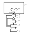
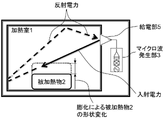
- FIG. 1 is a schematic configuration diagram of a microwave processing apparatus according to Embodiment 1 of the present disclosure.
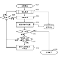
- FIG. 2 is a flow chart showing the overall flow of cooking control in the first embodiment.
- FIG. 3 is a flowchart showing details of reflected power detection processing according to the first embodiment.
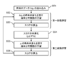
- FIG. 4 is a flow chart showing the flow of score calculation in the change finder.
- FIG. 5 is a diagram for explaining thresholds used for detecting a state change of the object to be heated according to the first embodiment.
- 6A and 6B are diagrams for explaining detection of state change of the object to be heated according to the first embodiment.
- FIG. FIG. 7 is a conceptual diagram showing boiling detection of an object to be heated according to the first embodiment.
- FIG. 8A is a diagram showing heating conditions in a proof experiment of boiling detection in Embodiment 1.
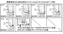
- FIG. 8B is a first diagram showing experimental results of boiling detection in Embodiment 1.
- FIG. 8C is a second diagram showing experimental results of boiling detection in Embodiment 1.
- FIG. 8D is a third diagram showing experimental results of boiling detection in Embodiment 1.
- FIG. 8E is a fourth diagram showing experimental results of boiling detection in Embodiment 1.
- FIG. FIG. 9 is a flow chart showing the overall flow of cooking control in the second embodiment.
- FIG. 10 is a flowchart showing details of reflected power detection processing according to the second embodiment.
- 11A and 11B are diagrams for explaining detection of state change of the object to be heated according to the second embodiment.
- FIGS. 12A and 12B are conceptual diagrams showing expansion detection of the object to be heated according to the second embodiment.
- 13A and 13B are diagrams for explaining detection of a change in the state of the object to be heated according to the third embodiment.
- 14A and 14B are conceptual diagrams showing melting detection of the object to be heated according to the third embodiment.
- 15A is a diagram for explaining heating conditions in a demonstration experiment of melting detection in Embodiment 3.
- FIG. 15B is a first diagram showing experimental results of melting detection in Embodiment 3.
- FIG. 15C is a second diagram showing experimental results of melting detection in Embodiment 3.
- FIG. FIG. 16 is a conceptual diagram showing thawing detection of the object to be heated according to the fourth embodiment.
- FIG. 17 is a conceptual diagram showing burst detection of the object to be heated according to the fifth embodiment.
- FIG. 18 is a conceptual diagram showing drying detection of the object to be heated according to the sixth embodiment.
- Patent Document 1 detects the boiling state of the object to be heated from changes in the reflected power and changes in the ratio of the sum of the reflected powers to the sum of the incident powers.
- the ratio of the total reflected power to the total incident power is referred to as reflectance.
- frequencies with large changes in the reflected power and frequencies with small changes in the boiling of the liquid since such frequency characteristics depend on the standing wave distribution of microwaves in the heating chamber, the frequency characteristics greatly affect the type, viscosity, amount, shape, placement position, shape of the heating chamber, etc. of the object to be heated. be done. The frequency characteristics are also affected by the type of state change of the object to be heated, such as swelling, melting, defrosting, bursting, and drying.
- a microwave processing apparatus includes a heating chamber containing an object to be heated, a heating unit including a microwave generating unit, an amplifying unit, a power supply unit, a detecting unit, a control unit, and a storage unit.
- the microwave generator generates microwaves with arbitrary frequencies in a predetermined frequency band.
- the amplifier amplifies the output level of the microwave.
- the feeding section radiates the microwave amplified by the amplifying section to the heating chamber as incident power.
- the detector detects the reflected power returning from the heating chamber to the power feeder, out of the incident power.
- the controller controls the microwave generator and amplifier.
- the storage unit stores the value of the reflected power along with the microwave frequency and the elapsed time from the start of heating.
- the control section controls the microwave generating section and the amplifying section based on a calculated value obtained by calculation with reference to the reflected power.
- control unit may use an average value of values calculated for each microwave frequency as the calculated value.
- the average value of the values calculated for each frequency is, for example, the average value of the reflected power values calculated for each frequency.
- control unit may calculate the calculated value for each microwave frequency.
- the controller may control the microwave generator when the calculated values for microwaves of two or more frequencies exceed thresholds.
- control unit obtains the calculated value using a change finder, which is an online change point detection method for time series data.
- the detector may further detect incident power.
- the storage unit may store the incident power value along with the microwave frequency and elapsed time.
- the control unit may calculate a reflectance, which is a ratio of the sum of the reflected powers to the sum of the incident powers, as the calculated value.
- the controller may control the microwave generator based on the reflectance.
- the storage unit may store the calculated value along with the elapsed time.
- the control unit may control the microwave generation unit when the calculated value exceeds a threshold that is greater than 1 times the minimum value of the calculated value stored in the storage unit and smaller than 3 times the minimum value. .
- control unit keeps the microwave generating unit until a predetermined time elapses from the start of heating even if the calculated value exceeds the threshold. No need to control.
- the microwave generation unit may be controlled. .
- the microwave generator may be controlled when the calculated value continuously exceeds the threshold value within a predetermined time.
- the controller detects boiling of the object to be heated as the state change of the object to be heated.
- control unit detects expansion of the object to be heated as the state change of the object to be heated.
- control unit detects melting of the object to be heated as the state change of the object to be heated.
- control unit detects thawing of the object to be heated as the state change of the object to be heated.
- the controller detects rupture of the object to be heated as the state change of the object to be heated.
- the controller detects drying of the object to be heated as the state change of the object to be heated.
- control unit may stop heating after detecting a change in the state of the object to be heated.
- the heating conditions in the heating unit may be changed after detecting the state change of the object to be heated.
- FIG. 1 is a schematic configuration diagram of a microwave processing apparatus according to Embodiment 1 of the present disclosure.
- the microwave treatment according to the first embodiment includes a heating chamber 1, a microwave generator 3, an amplifier 4, a power feeder 5, a detector 6, and a controller 7. , and a storage unit 8 .
- the microwave generating section 3 corresponds to the heating section.
- the heating chamber 1 accommodates an object to be heated 2 such as food as a load.
- the microwave generator 3 is composed of a semiconductor element.
- the microwave generator 3 can generate microwaves of any frequency in a predetermined frequency band, and generates microwaves of a frequency specified by the controller 7 .
- the amplifier 4 is composed of a semiconductor element.
- the amplifier 4 amplifies the output level of the microwave generated by the microwave generator 3 according to an instruction from the controller 7 and outputs the amplified microwave.
- the feeding section 5 functions as an antenna and supplies the microwave amplified by the amplifying section 4 to the heating chamber 1 as incident power. That is, the power supply unit 5 supplies incident power based on the microwaves generated by the microwave generation unit 3 to the heating chamber 1 . Of the incident power, the power that is not consumed by the object to be heated 2 or the like becomes reflected power that returns from the heating chamber 1 to the power supply unit 5 .
- the detection unit 6 is composed of, for example, a directional coupler.
- the detector 6 detects the value of the incident power and the value of the reflected power, and notifies the controller 7 of the information. That is, the detector 6 functions as both an incident power detector and a reflected power detector.
- the detection unit 6 has a degree of coupling of, for example, approximately -40 dB, and extracts approximately 1/10000 of the incident power and the reflected power.
- the extracted incident power is rectified by a detector diode (not shown), smoothed by a capacitor (not shown), and converted into information corresponding to the incident power.
- the extracted reflected power is similarly converted into information corresponding to the reflected power by rectification and smoothing.
- the control unit 7 receives these pieces of information.
- the storage unit 8 is a storage medium such as a semiconductor memory, stores data from the control unit 7 , reads out the stored data, and transmits it to the control unit 7 .
- the control unit 7 is composed of a microprocessor including a CPU (central processing unit).
- the control unit 7 controls the microwave generation unit 3 and the amplification unit 4 based on the information from the detection unit 6 and the storage unit 8, and executes cooking control in the microwave processing apparatus.
- the control unit 7 causes the storage unit 8 (the first storage unit of the storage unit 8) to store the frequency of the microwave generated by the microwave generation unit 3, the elapsed time from the start of heating, and the value of the reflected power.
- the control unit 7 refers to the value of the reflected power stored in the storage unit 8 and performs calculations, and controls the microwave generation unit 3 based on the obtained calculation value RF.
- the control unit 7 stores the calculated value RF in the storage unit 8 (second storage unit of the storage unit 8).
- the calculated value RF is, for example, a value indicating the amount of change in reflected power. A value indicating the amount of change in reflected power will be described later.
- the control unit 7 uses the average value of the values calculated for each microwave frequency as the calculated value RF.
- the average value of the values calculated for each frequency is, for example, the average value of the reflected power values calculated for each frequency.
- the control unit 7 uses the value calculated by the change finder as the calculated value RF.
- Changefinder is an online change-point detection method for time-series data.
- the control unit 7 stores the calculated value RF in the storage unit 8 (second storage unit of the storage unit 8) along with the elapsed time from the start of heating.
- the controller 7 controls the microwave generator 3 to adjust the microwave power when the calculated value RF exceeds the threshold TH.
- the threshold TH is a value that is larger than 1 times the minimum value of the calculated value RF and smaller than 3 times the minimum value of the calculated value RF.
- control unit 7 does not control the microwave generation unit 3 until a predetermined time has passed since the start of heating.
- the storage unit 8 is a single semiconductor memory, in which a first storage unit and a second storage unit are configured.
- the first memory section and the second memory section may be composed of separate semiconductor memories.
- control unit 7 detects boiling of the object 2 to be heated in the heating chamber 1 .
- the controller 7 causes the microwave generator 3 to stop generating microwaves after boiling is detected.
- FIG. 2 is a flow chart showing the overall flow of cooking control in the first embodiment.
- the control unit 7 when the control unit 7 causes the microwave generation unit 3 to generate microwaves and starts heating (step S1), the control unit 7 first performs reflected power detection processing (step S2). .
- FIG. 3 is a flowchart showing the details of detection processing. As shown in FIG. 3, when the detection process starts (step S11), the microwave generator 3 sweeps the frequency (step S12). Frequency sweeping is an operation of the microwave generator 3 that sequentially changes the frequency at predetermined frequency intervals over a predetermined frequency band (eg, 2400 MHz to 2500 MHz).
- a predetermined frequency band eg, 2400 MHz to 2500 MHz.
- the detection unit 6 detects the reflected power for the microwave of each frequency during the frequency sweep.
- the control unit 7 measures the frequency characteristics of the reflected power from the detected reflected power (step S13).
- the control unit 7 stores each frequency in the frequency sweep, the reflected power value for each frequency obtained in the measurement process, and the elapsed time from the start of heating in the storage unit 8 (first storage unit of the storage unit 8). It is stored (step S14).
- the control unit 7 obtains a calculated value RF used for boiling detection based on the obtained frequency characteristics of the reflected power (step S14), and terminates the detection process (step S15).
- the control unit 7 returns the process to the flowchart shown in FIG. 2, and heats the object 2 to be heated by microwave heating in the heating process (step S3).
- the control unit 7 grasps the boiling state of the object to be heated 2 from the information obtained by the detection process (step S4). In the end determination (step S5), the control unit 7 determines whether or not the object to be heated 2 is in a boiling state.
- control unit 7 determines that the object to be heated 2 is in a boiling state, it ends cooking (step S6). Otherwise, the control unit 7 continues cooking, determines new heating conditions as necessary (step S7), and advances the process to step S8.
- step S8 the control unit 7 determines whether or not it is necessary to update the frequency characteristic due to the lapse of a certain period of time from the start of heating or due to a change in heating conditions.
- the control unit 7 returns the process to the detection process (step S2) if the update is required, and returns the process to the heating process (step S3) if the update is not required.
- a change finder is a method of calculating a score representing the degree of change in time-series data in real time.
- non-patent documents 1 to 3 are typical documents related to change finders.
- FIG. 4 is a flow chart showing the flow of score calculation in the change finder.
- the change finder uses a method based on two-stage learning of the time-series model, and its processing is roughly divided into steps S51 to S56.
- time series data is read in step S51.
- the time-series data in the present disclosure includes microwave frequency, elapsed time from the start of heating, incident power, reflected power, and reflectance.
- step S52 the probability distribution function is learned.
- step S53 a score is calculated.
- An AR model autoregressive model
- SDAR sequentialially discounting AR learning
- step S54 the score calculated in step S53 is smoothed. Smoothing is to obtain the average value of the outlier scores obtained in steps S51 and S52 for the data within the window of predetermined integer T width. A new moving average score time series is constructed by shifting the window.
- a probability distribution function is learned in step S55, and a score is calculated in step S56.
- the processes of steps S55 and S56 are collectively called second stage learning.
- the AR model is used to model the new time-series data smoothed in step S54, and the SDAR algorithm is used again for learning.
- the obtained probability model data at each time point is calculated using the logarithmic loss or the Hellinger distance as in steps S52 and S53 to calculate the score. The higher the score, the higher the degree of change at each time point.
- the advantages of changefinders are as follows.
- the first-stage learning can only detect outliers in time series. However, after smoothing outlier scores to remove noise-sensitive outliers, only essential variations can be detected by a second iteration of training.
- the predetermined integer T used in the description of step S54 is defined as "smooth”.
- the SDAR algorithm performs computations iteratively, it updates the parameters, or statistics required for the computation, in the form of a weighted average of the ratio (1 ⁇ r):r of the current and new values. .
- 'r' is a forgetting parameter with a value in the range 0 ⁇ r ⁇ 1. The smaller "r" is, the more sensitive the SDAR algorithm is to past data. Also in Embodiments 1 and 3, the forgetting parameter is defined as "r".
- the score calculated in the first stage learning is a value before smoothing the score. Therefore, the score calculated in the first-stage learning is effective in detecting smaller state changes of the object 2 to be heated.
- FIG. 5 is a diagram for explaining the threshold TH used for detecting the state change of the object to be heated 2 in the first embodiment.
- the calculated value RF and the threshold TH are shown on the graph in FIG.
- the horizontal axis indicates the elapsed time (minutes) from the start of heating
- the vertical axis indicates the calculated value RF.
- the unit of the vertical axis in FIG. 5, that is, the unit of the calculated value RF and the threshold TH is determined by which value is used as the calculated value RF. For example, when the calculated value RF is the average value of the reflected power values, the unit of the vertical axis in FIG. 5 is power (W). Similarly, when the calculated value RF is the standard deviation of the reflected power values, the unit of the vertical axis is power (W). When the calculated value RF is a value calculated by the change finder method, the unit of the vertical axis in FIG. 5 is dimensionless.
- the threshold TH is a value that is larger than 1 times the minimum value of the calculated value RF and smaller than 3 times the minimum value of the calculated value RF. A method of determining the threshold TH based on the calculated value RF from the start of heating will be described.
- the threshold value TH is calculated by multiplying the minimum value of the calculated value RF from the start of heating by a predetermined magnification.
- this magnification is a value greater than 1 and less than 3.
- the controller 7 multiplies the new minimum value by the same magnification to update the threshold TH.
- the minimum value of the calculated value RF is the minimum value of the calculated value RF obtained from the reflected power detected up to that point. Therefore, as shown in FIG. 5, when the calculated value RF decreases over time, the threshold TH decreases along with the change. On the other hand, when the calculated value RF increases over time, the threshold TH remains unchanged.
- the threshold TH for detection determination is not set in advance.
- the control unit 7 refers to the reflected power and the incident power stored in the storage unit 8 (the first storage unit of the storage unit 8), and sets the threshold value TH for each of the objects to be heated having different weights, shapes, and containers. decide.
- flexible detection can be performed in consideration of variations in the object to be heated 2 expected in actual cooking.
- the possibility of erroneous detection can be reduced, and highly accurate detection becomes possible.
- the threshold TH is a value larger than 1 and smaller than 3 times the minimum value of the reflectance.
- reflectance is the ratio of the sum of reflected power to the sum of incident power.
- the optimal value for the multiplier to be multiplied by the minimum value of the calculated value RF also changes. Therefore, the storage unit 8 preliminarily stores setting conditions suitable for the type and weight of the object to be heated 2 .
- the control unit 7 reads and uses the optimum setting conditions from the storage unit 8 based on information such as the type and weight of the object to be heated 2 input by the user. Thereby, detection accuracy can be improved.
- FIG. 6 is a diagram for explaining detection of state change of the object to be heated 2 in the first embodiment.
- the horizontal axis indicates the elapsed time (minutes) from the start of heating
- the vertical axis indicates the calculated value RF.
- the calculated value RF and the threshold TH are shown on the graph in FIG.
- the units of the vertical and horizontal axes in FIG. 6 are the same as in FIG.
- the control unit 7 keeps the object to be heated until a predetermined time TMa (guard time) elapses from the start of heating.
- TMa guard time
- Such a case is, for example, a case where the reflected power momentarily changes significantly due to a cause other than the phenomenon in which the object 2 to be heated continuously changes its state. This includes the case where the operation of the detector 6 is not stable.
- a phenomenon other than a change in the state of the object to be heated 2 that causes a large instantaneous change in the reflected power is, for example, deformation of the wall surface of the heating chamber 1 caused by expansion due to temperature rise. Deformation of the object to be heated 2 having an unstable shape is one of such phenomena.
- the storage unit 8 preliminarily stores setting conditions suitable for the type and weight of the object to be heated 2 .
- the control unit 7 reads and uses the optimum setting conditions from the storage unit 8 based on information such as the type and weight of the object to be heated 2 input by the user. Thereby, detection accuracy can be improved.
- FIG. 7 is a conceptual diagram showing boiling detection of the object to be heated 2 in the first embodiment.
- the object to be heated 2 is liquid.
- microwaves may or may not be absorbed by the object to be heated 2 depending on the shaking of the surface during boiling. Therefore, when the object to be heated boils, the reflected power fluctuates greatly. That is, boiling of the object 2 to be heated can be detected by calculating the amount of change in the reflected power.
- the value that indicates the amount of change in reflected power is the standard deviation, variance, and coefficient of determination of the reflected power value per arbitrary time, the score calculated by the changefinder method, and the change in reflected power per arbitrary time. Includes rate and range.
- the value indicating the amount of change in reflected power further includes a frequency-averaged reflected power value and a reflected power value for each frequency.
- the frequency average is the average value of multiple reflected power values.
- Each of the plurality of reflected power values is obtained for a corresponding one of the plurality of frequencies.
- the values that indicate the variation in the amount of change in reflected power such as variance, standard deviation, and coefficient of determination, increase. Therefore, boiling of the object to be heated 2 can be detected by calculating variations in the amount of change in the reflected power.
- the variance may be sample variance or nonuniform variance. Variance may be overestimated using the sample variance. For this reason, it may be more appropriate to use the coefficient of determination rather than the sample variance to assess small variability.
- the sample variance is defined by the following formula.
- covariance is the average value of the values obtained by multiplying the deviation of one variable by the deviation of another variable. Covariance represents the trend of variability of two variables.
- the coefficient of determination is defined by the following formula.
- control unit 7 By detecting the boiling of the object 2 to be heated, the control unit 7 can change the heating conditions or end the heating. This can prevent overheating or underheating. As a result, the cooking can be finished optimally.
- Some cooking such as pot-au-feu, requires the ingredients in the object to be heated 2 to be sufficiently heated by continuing to boil for a certain period of time.
- a weak boiling state can be maintained by duty-controlling the microwave output after detecting boiling.
- Duty control is a control method that repeatedly outputs a constant level signal while adjusting the ratio of ON and OFF.
- Cooking that requires duty control of microwave output after boiling is detected is, for example, cooking of soups such as pot-au-feu and stew, and heating of drinks such as milk and water.
- FIG. 8A shows the heating conditions in the boiling detection demonstration experiments for water, pot-au-feu and stew.
- FIGS. 8B to 8E the horizontal axis indicates the heating time (minutes), and the vertical axis indicates the change finder score.
- Each graph in FIGS. 8B to 8E shows changes in changefinder scores over time and changes in threshold TH over time. Each graph further shows the time when one of the four optical fiber thermometer probes inserted into the heated object 2 detects 100°C and the time when all of them detect 100°C.
- the state change of the object to be heated 2 can be detected.
- the calculated score varies greatly depending on the setting conditions. Therefore, the storage unit 8 preliminarily stores setting conditions suitable for the type and weight of the object to be heated 2 .
- the control unit 7 reads and uses the optimum setting conditions from the storage unit 8 based on information such as the type and weight of the object to be heated 2 input by the user. Thereby, detection accuracy can be improved.
- Embodiment 1 it is possible to accurately detect boiling for heated objects 2 having different weights, shapes, materials, placement positions, etc., and optimal cooking can be achieved.
- a microwave processing apparatus according to Embodiment 2 of the present disclosure has the same configuration as the microwave processing apparatus according to Embodiment 1 shown in FIG. Therefore, in the second embodiment, the same or substantially the same constituent elements as those in the first embodiment are denoted by the same reference numerals, and overlapping descriptions are omitted.
- control unit 7 refers to the reflected power stored in the storage unit 8 (the first storage unit of the storage unit 8) and performs calculations for each frequency of the microwave.
- the control unit 7 determines that a change in the state of the object to be heated 2 has been detected when the calculated value RF obtained for microwaves of two or more frequencies exceeds the threshold TH.
- the control unit 7 causes the storage unit 8 (the first storage unit of the storage unit 8) to store the incident power value and the reflected power value together with the microwave frequency and the elapsed time from the start of heating. .
- the control unit 7 calculates the reflectance from the incident power and the reflected power stored in the storage unit 8, and controls the microwave generation unit 3 based on the reflectance.
- reflectance is the ratio of the sum of reflected power to the sum of incident power.
- the control unit 7 It controls the microwave generator 3 .
- control unit 7 detects expansion of the object 2 to be heated in the heating chamber 1 as the state change of the object 2 to be heated.
- the microwave processing apparatus includes a radiation heater and a steam generator (both not shown) in addition to the microwave generator 3 as heating units.
- the heating unit may include both or one of the radiant heater and the steam generator, and does not necessarily include both.
- the control unit 7 After detecting the expansion of the object 2 to be heated, the control unit 7 changes the heating conditions including changing the heating unit to be used.
- Changing the heating unit to be used means, for example, changing the heating unit to be used from the microwave generator 3 to a radiation heater or a steam generator in the heat treatment. The opposite is also possible.
- FIG. 9 is a flow chart showing the overall flow of cooking control in the second embodiment. As shown in FIG. 9, when the control unit 7 controls the microwave generation unit 3 to start heating (step S21), the control unit 7 first performs reflected power detection processing (step S22).
- FIG. 10 is a flowchart showing the details of detection processing. As shown in FIG. 10, when the detection process starts (step S31), the microwave generator 3 sweeps the frequency (step S32).
- the detection unit 6 detects reflected power and incident power for microwaves of each frequency during the frequency sweep.
- the controller 7 measures the frequency characteristics of the reflected power, the frequency characteristics of the incident power, and the reflectance from the detected reflected power and incident power (step S33).
- the control unit 7 causes the storage unit 8 (the first storage unit of the storage unit 8) to store each frequency in the frequency sweep and the reflected power, incident power, and reflectance for each frequency obtained in the measurement process.
- the control unit 7 also stores the elapsed time from the start of heating in the storage unit 8 (first storage unit of the storage unit 8) (step S34). Based on the two obtained frequency characteristics, the control unit 7 obtains a calculated value RF used for detecting swelling (step S34), and terminates the detection process (step S35).
- the control unit 7 returns the process to the flowchart shown in FIG. 9, and starts heating the object 2 to be heated by microwave heating in the heating process (step S23).
- the control unit 7 may use oven heating or radiation heating using a radiation heater, or steam heating using a steam generator.
- the control unit 7 grasps the swelling state of the heated object 2 from the information obtained by the detection process (step S24). In the end determination (step S25), the control unit 7 determines whether or not the object to be heated 2 is in a swollen state.
- control unit 7 determines whether to maintain the same heating conditions or change the heating conditions including changing the heating unit to be used according to the swelling state of the object 2 to be heated (step S27).
- step S28 the control unit 7 determines whether updating of the frequency characteristic is necessary due to a lapse of a certain period of time from the start of heating, a change in heating conditions, or the like.
- the control unit 7 returns the process to the detection process (step S22) if the update is required, and returns the process to the heating process (step S23) if the update is not required.
- step S27 If it is determined in step S27 that the heating conditions should be changed, the control unit 7 determines new heating conditions including changing the heating unit to be used (step S29), and advances the process to step S28.
- the microwave generator 3 In the frequency sweep, the microwave generator 3 generates microwaves by sequentially increasing the frequency at predetermined frequency intervals from the lower limit of the predetermined frequency band.
- the control unit 7 measures the frequency characteristics of the reflectance and selects the frequency that gives the lowest reflectance based on the obtained frequency characteristics.
- the method of selecting the frequency that gives the lowest reflectance is not limited to this.
- the microwave generator 3 may randomly change the frequency in a predetermined frequency band to generate microwaves.
- the control unit 7 may obtain the reflectance for each frequency and select the frequency that gives the lowest reflectance.
- FIG. 11 is a diagram for explaining detection of state change of the object to be heated 2 in the second embodiment.
- the horizontal axis indicates the elapsed time (minutes) from the start of heating
- the vertical axis indicates the calculated value RF obtained by referring to the reflected power stored in the storage unit 8 (the first storage unit of the storage unit 8).
- the graph of FIG. 11 shows the calculated value RF and the threshold TH.
- the units of the vertical and horizontal axes in FIG. 11 are the same as in FIG.
- the control unit 7 detects that the state change of the object to be heated 2 is determined to have occurred.
- Such a case is, for example, a case where the reflected power momentarily changes significantly due to a cause other than the phenomenon in which the object 2 to be heated continuously changes its state. This includes the case where the operation of the detector 6 is not stable.
- a phenomenon other than a change in the state of the object to be heated 2 that causes a large instantaneous change in the reflected power is, for example, deformation of the wall surface of the heating chamber 1 caused by expansion due to temperature rise. Deformation of the object to be heated 2 having an unstable shape is one of such phenomena.
- the predetermined time TMb it is preferable to set the predetermined time TMb to 1 second or more. This is because it is difficult to imagine that the above phenomenon continues to occur for more than one second. Further, as described above, when the threshold value TH is exceeded multiple times within the predetermined time TMb, it is determined that the state of the object to be heated 2 has changed, thereby improving the detection accuracy. In practice, it is preferable to set this number to a value between 2 and 10.
- FIG. 12 is a conceptual diagram showing expansion detection of the object to be heated 2 in the second embodiment. As shown in FIG. 12, the shape of the object 2 to be heated changes due to the expansion of the object 2 to be heated, and the object 2 to be heated dries.
- the dielectric constant of the object to be heated 2 as a whole changes, and the distribution of the dielectric constant in the object to be heated 2 also changes. This also changes the frequency characteristics of the absorbed power. As a result, expansion of the object 2 to be heated can be detected by calculating the amount of change in reflected power during heating of the object 2 to be heated. Absorbed power means microwaves absorbed by the object 2 to be heated.
- the value that indicates the amount of change in reflected power is the standard deviation, variance, and coefficient of determination of the reflected power value per arbitrary time, the score calculated by the changefinder method, and the change in reflected power per arbitrary time. Includes rate and range.
- the value indicating the amount of change in reflected power further includes a frequency-averaged reflected power value and a reflected power value for each frequency. Generally, when the object 2 to be heated dries, the dielectric constant decreases.
- the control unit 7 can change the heating conditions or end the heating by detecting the start and completion of expansion of the object 2 to be heated. This can prevent overheating or underheating. As a result, the cooking can be finished optimally.
- Cooking using puffing detection is, for example, baking soufflé and cream puff pastry and bread.
- Embodiment 2 it is possible to accurately detect expansion of objects 2 to be heated having different weights, shapes, materials, placement positions, etc., and optimally finish cooking.
- a microwave processing apparatus according to Embodiment 3 of the present disclosure has the same configuration as the microwave processing apparatus according to Embodiment 1 shown in FIG. Accordingly, in the third embodiment, the same or substantially the same constituent elements as those in the first embodiment are denoted by the same reference numerals, and overlapping descriptions are omitted.
- control unit 7 detects melting of the object 2 to be heated in the heating chamber 1 as the state change of the object 2 to be heated.
- FIG. 13 is a diagram for explaining detection of a state change of the object to be heated 2 in the third embodiment.
- the horizontal axis indicates the elapsed time (minutes) from the start of heating
- the vertical axis indicates the calculated value RF obtained by referring to the reflected power stored in the storage unit 8 (the first storage unit of the storage unit 8).
- the graph of FIG. 13 shows the calculated value RF and the threshold TH.
- the units of the vertical and horizontal axes in FIG. 13 are the same as in FIG.
- the control unit 7 detects the state change of the object 2 to be heated. It is determined that
- Such a case is, for example, a case where the reflected power momentarily changes significantly due to a cause other than the phenomenon in which the object 2 to be heated continuously changes its state. This includes the case where the operation of the detector 6 is not stable.
- a phenomenon other than a change in the state of the object to be heated 2 that causes a large instantaneous change in the reflected power is, for example, deformation of the wall surface of the heating chamber 1 caused by expansion due to temperature rise. Deformation of the object to be heated 2 having an unstable shape is one of such phenomena.
- the predetermined time TMc it is preferable to set the predetermined time TMc to 1 second or more. This is because it is difficult to imagine that the above phenomenon continues to occur for more than one second.
- FIG. 14 is a conceptual diagram showing detection of melting of the object to be heated 2 in the third embodiment. As shown in FIG. 14, the material to be heated 2 is deformed by melting.
- the dielectric constant of the object to be heated 2 as a whole changes, and the distribution of the dielectric constant in the object to be heated 2 also changes. This changes the frequency characteristic of the absorbed power. As a result, melting of the object 2 to be heated can be detected by calculating the amount of change in reflected power during heating of the object 2 to be heated.
- the value that indicates the amount of change in reflected power is the standard deviation, variance, and coefficient of determination of the reflected power value per arbitrary time, the score calculated by the changefinder method, and the change in reflected power per arbitrary time. Includes rate and range.
- the value indicating the amount of change in reflected power further includes a frequency-averaged reflected power value and a reflected power value for each frequency.
- the dielectric constant increases when the object to be heated 2 melts.
- the control unit 7 can change the heating conditions or end the heating by detecting the start and completion of melting of the object 2 to be heated. This can prevent overheating or underheating. As a result, the cooking can be finished optimally.
- Cooking that uses melting detection is, for example, melting butter and chocolate.
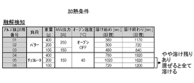
- FIG. 15A shows heating conditions in a demonstration experiment of melting detection for butter and chocolate.
- FIGS. 15B and 15C the horizontal axis indicates the heating time (minutes), and the vertical axis indicates the change finder score.
- Each graph in FIGS. 15B and 15C shows the score of the change finder, the threshold TH, and the time at which the object to be heated 2 started to melt.
- the calculated score varies greatly depending on the setting conditions. Therefore, the storage unit 8 preliminarily stores setting conditions suitable for the type and weight of the object to be heated 2 .
- the control unit 7 reads and uses the optimum setting conditions from the storage unit 8 based on information such as the type and weight of the object to be heated 2 input by the user. Thereby, detection accuracy can be improved.
- Embodiment 3 it is possible to accurately detect melting of objects 2 to be heated having different weights, shapes, materials, placement positions, etc., and optimally finish cooking.
- a microwave processing apparatus according to Embodiment 4 of the present disclosure has the same configuration as the microwave processing apparatus according to Embodiment 1 shown in FIG. Therefore, in the fourth embodiment, the same or substantially the same constituent elements as those in the first embodiment are denoted by the same reference numerals, and overlapping descriptions are omitted.
- the control unit 7 detects thawing of the object 2 to be heated as the state change of the object 2 to be heated.
- FIG. 16 is a conceptual diagram showing thawing detection of the object to be heated 2 in the fourth embodiment. As shown in FIG. 16, the object to be heated 2 is deformed by thawing.
- the dielectric constant of the object to be heated 2 as a whole changes, and the distribution of the dielectric constant in the object to be heated 2 also changes. This changes the frequency characteristic of the absorbed power. As a result, thawing of the object 2 to be heated can be detected by calculating the amount of change in reflected power during heating of the object 2 to be heated.
- the value that indicates the amount of change in reflected power is the standard deviation, variance, and coefficient of determination of the reflected power value per arbitrary time, the score calculated by the changefinder method, and the change in reflected power per arbitrary time. Includes rate and range.
- the value indicating the amount of change in reflected power further includes a frequency-averaged reflected power value and a reflected power value for each frequency. Generally, the dielectric constant increases when the object 2 to be heated is thawed.
- control unit 7 By detecting the start and completion of thawing of the object 2 to be heated, the control unit 7 can change the heating conditions or end the heating. This can prevent overheating or underheating. As a result, the cooking can be finished optimally.
- Cooking that uses thawing detection is, for example, thawing frozen meat, frozen fish, frozen vegetables, and ice.
- Embodiment 4 it is possible to accurately detect thawing of objects 2 to be heated having different weights, shapes, materials, placement positions, etc., and optimal cooking can be achieved.
- Embodiment 5 A microwave processing apparatus according to Embodiment 5 of the present disclosure has the same configuration as the microwave processing apparatus according to Embodiment 1 shown in FIG. Therefore, in the fifth embodiment, the same or substantially the same constituent elements as those in the first embodiment are denoted by the same reference numerals, and overlapping descriptions are omitted.
- the control unit 7 detects bursting of the object to be heated 2 as the state change of the object to be heated 2 .
- ⁇ Rupture detection> 17A and 17B are conceptual diagrams showing burst detection of the object to be heated 2 in the fifth embodiment.
- the rupture changes the shape of the object 2 to be heated and the position in which the object 2 is placed in the heating chamber 1 . These changes change the frequency characteristics of the absorbed power.
- the amount of change in the reflected power during heating of the object 2 to be heated it is possible to detect the explosion of the object 2 to be heated.
- the value that indicates the amount of change in reflected power is the standard deviation, variance, and coefficient of determination of the reflected power value per arbitrary time, the score calculated by the changefinder method, and the change in reflected power per arbitrary time. Includes rate and range.
- the value indicating the amount of change in reflected power further includes a frequency-averaged reflected power value and a reflected power value for each frequency.
- the control unit 7 can change the heating conditions or end the heating by detecting the explosion of the object 2 to be heated. This can prevent overheating or underheating. As a result, the cooking can be finished optimally.
- An example of cooking that uses burst detection is making bopped corn.
- Embodiment 5 it is possible to accurately detect the explosion of objects 2 to be heated having different weights, shapes, materials, placement positions, etc., and optimally finish cooking.
- Embodiment 6 A microwave processing apparatus according to Embodiment 6 of the present disclosure has the same configuration as the microwave processing apparatus according to Embodiment 1 shown in FIG. Therefore, in the sixth embodiment, the same or substantially the same constituent elements as those in the first embodiment are denoted by the same reference numerals, and overlapping descriptions are omitted.
- the control unit 7 detects drying of the object 2 to be heated as the state change of the object 2 to be heated.
- FIG. 18 is a conceptual diagram showing drying detection of the object to be heated 2 in the sixth embodiment. As shown in FIG. 18, the object to be heated 2 is deformed by drying.
- the dielectric constant of the object to be heated 2 as a whole changes, and the distribution of the dielectric constant in the object to be heated 2 also changes. This changes the frequency characteristic of the absorbed power. As a result, by calculating the amount of change in reflected power during heating of the object 2 to be heated, drying of the object 2 to be heated can be detected.
- the value that indicates the amount of change in reflected power is the standard deviation, variance, and coefficient of determination of the reflected power value per arbitrary time, the score calculated by the changefinder method, and the change in reflected power per arbitrary time. Includes rate and range.
- the value indicating the amount of change in reflected power further includes a frequency-averaged reflected power value and a reflected power value for each frequency. Generally, when the object 2 to be heated dries, the dielectric constant decreases.
- the control unit 7 can change the heating conditions or end the heating by detecting the start of drying and the completion of drying of the object 2 to be heated. This can prevent overheating or underheating. As a result, the cooking can be finished optimally.
- drying using dryness detection is the creation of dried fruits, dried vegetables, and dried meat. Dryness detection can also be used to reduce excess moisture in foods.
- Non-cooking dryness sensing applications include microwave drying of wood, clothes, etc.
- Embodiment 6 it is possible to accurately detect the dryness of heated objects 2 having different weights, shapes, materials, placement positions, etc., and optimally finish cooking.
- the microwave processing device is a microwave heating device for industrial applications such as a heating cooker that dielectrically heats food, a drying device, a heating device for pottery, a garbage processor, a semiconductor manufacturing device, a chemical reaction device, etc. applicable to
Landscapes
- Physics & Mathematics (AREA)
- Electromagnetism (AREA)
- Control Of High-Frequency Heating Circuits (AREA)
Abstract
Description
特許文献1に記載のマイクロ波処理装置は、反射電力の変化および入射電力の総和に対する反射電力の総和の割合の変化から被加熱物の沸騰状態を検知する。以下、入射電力の総和に対する反射電力の総和の割合を反射率という。
<全体構成>
図1は、本開示の実施の形態1に係るマイクロ波処理装置の概略構成図である。図1に示すように、実施の形態1に係るマイクロ波処理処置は、加熱室1と、マイクロ波発生部3と、増幅部4と、給電部5と、検出部6と、制御部7と、記憶部8とを備える。実施の形態1において、マイクロ波発生部3は加熱部に相当する。
図2は、実施の形態1における調理制御全体の流れを示すフローチャートである。図2に示すように、制御部7がマイクロ波発生部3にマイクロ波を発生させて加熱を開始すると(ステップS1)、最初に、制御部7は反射電力の検出処理(ステップS2)を行う。
チェンジファインダとは、リアルタイムに時系列データの変化の度合いを表すスコアを計算する方法である。チェンジファインダに関する代表的な文献は例えば、非特許文献1~3である。
図7は、実施の形態1における被加熱物2の沸騰検知を示す概念図である。図7において、被加熱物2は液体である。


図8A~図8Eは、実施の形態1における沸騰検知の実験結果を示す図である。図8Aは、水、ポトフおよびシチューに対する沸騰検知の実証実験における加熱条件を示す。
<全体構成>
本開示の実施の形態2のマイクロ波処理装置は、図1に示す実施の形態1のマイクロ波処理装置と同じ構成を備える。従って、実施の形態2において、実施の形態1と同一または実質同一の構成要素については同一の符号を付し、重複する説明を省略する。
図9は、実施の形態2における調理制御全体の流れを示すフローチャートである。図9に示すように、制御部7がマイクロ波発生部3を制御して加熱を開始すると(ステップS21)、最初に、制御部7は反射電力の検出処理(ステップS22)を行う。
図12は、実施の形態2における被加熱物2の膨化検知を示す概念図である。図12に示すように、被加熱物2の膨化により被加熱物2の形状が変化するとともに被加熱物2は乾燥する。
<全体構成>
本開示の実施の形態3のマイクロ波処理装置は、図1に示す実施の形態1のマイクロ波処理装置と同じ構成を備える。従って、実施の形態3において、実施の形態1と同一または実質同一の構成要素については同一の符号を付し、重複する説明を省略する。
図14は、実施の形態3における被加熱物2の融解検知を示す概念図である。図14に示すように、融解により被加熱物2は変形する。
図15A~図15Cは、実施の形態3における融解検知の実験結果を示す図である。図15Aは、バターおよびチョコレートに対する融解検知の実証実験における加熱条件を示す。
<全体構成>
本開示の実施の形態4のマイクロ波処理装置は、図1に示す実施の形態1のマイクロ波処理装置と同じ構成を備える。従って、実施の形態4において、実施の形態1と同一または実質同一の構成要素については同一の符号を付し、重複する説明を省略する。実施の形態4において、制御部7は、被加熱物2の状態変化として、被加熱物2の解凍を検知する。
図16は、実施の形態4における被加熱物2の解凍検知を示す概念図である。図16に示すように、解凍により被加熱物2は変形する。
本開示の実施の形態5のマイクロ波処理装置は、図1に示す実施の形態1のマイクロ波処理装置と同じ構成を備える。従って、実施の形態5において、実施の形態1と同一または実質同一の構成要素については同一の符号を付し、重複する説明を省略する。実施の形態5において、制御部7は、被加熱物2の状態変化として、被加熱物2の破裂を検知する。
図17は、実施の形態5における被加熱物2の破裂検知を示す概念図である。図17に示すように、破裂により、被加熱物2の形状および被加熱物2の加熱室1における載置位置は変化する。これらの変化により、吸収電力の周波数特性が変化する。その結果、被加熱物2の加熱中の反射電力の変化量を算出することで、被加熱物2の破裂を検知することができる。
本開示の実施の形態6のマイクロ波処理装置は、図1に示す実施の形態1のマイクロ波処理装置と同じ構成を備える。従って、実施の形態6において、実施の形態1と同一または実質同一の構成要素については同一の符号を付し、重複する説明を省略する。実施の形態6において、制御部7は、被加熱物2の状態変化として、被加熱物2の乾燥を検知する。
図18は、実施の形態6における被加熱物2の乾燥検知を示す概念図である。図18に示すように、乾燥により被加熱物2は変形する。
2 被加熱物
3 マイクロ波発生部
4 増幅部
5 給電部
6 検出部
7 制御部
8 記憶部
Claims (17)
- 被加熱物を収容するように構成された加熱室と、
所定の周波数帯域における任意の周波数を有するマイクロ波を発生するように構成されたマイクロ波発生部を含む加熱部と、
前記マイクロ波の出力レベルを増幅するように構成された増幅部と、
前記増幅部により増幅された前記マイクロ波を入射電力として前記加熱室に放射するように構成された給電部と、
前記入射電力のうち前記加熱室から前記給電部に戻る反射電力を検出するように構成された検出部と、
前記マイクロ波発生部および前記増幅部を制御する制御部と、
前記マイクロ波の周波数および加熱開始からの経過時間とともに前記反射電力の値を記憶するように構成された記憶部と、を備え、
前記制御部は、前記反射電力を参照した演算により得られた演算値に基づいて、前記マイクロ波発生部および前記増幅部を制御するように構成された、マイクロ波処理装置。 - 前記制御部は、前記演算値として、前記マイクロ波の前記周波数ごとに算出した値の平均値を用いるように構成された、請求項1に記載のマイクロ波処理装置。
- 前記制御部は、前記演算値を前記マイクロ波の前記周波数ごとに算出し、
前記制御部は、2つ以上の周波数の前記マイクロ波に対する前記演算値が閾値を超えた場合に、前記マイクロ波発生部を制御するように構成された、請求項1に記載のマイクロ波処理装置。 - 前記制御部は、時系列データに対するオンライン変化点検出手法であるチェンジファインダを用いて前記演算値を求めるように構成された、請求項1~3のいずれか1項に記載のマイクロ波処理装置。
- 前記検出部はさらに、前記入射電力を検出するように構成され、
前記記憶部は、前記マイクロ波の前記周波数および前記経過時間とともに前記入射電力の値を記憶するように構成され、
前記制御部は、前記演算値として、前記入射電力の総和に対する前記反射電力の総和の割合である反射率を算出し、
前記制御部は、前記反射率に基づいて前記マイクロ波発生部を制御するように構成された、請求項1に記載のマイクロ波処理装置。 - 前記制御部は、前記演算値を前記経過時間とともに前記記憶部に記憶させ、
前記制御部は、前記演算値の最小値の1倍より大きく、かつ前記演算値の前記最小値の3倍より小さい閾値を前記演算値が超えた場合に、前記マイクロ波発生部を制御するように構成された、請求項1に記載のマイクロ波処理装置。 - 前記制御部は、前記演算値が前記閾値を超えても前記加熱開始から所定の時間が経過するまでは前記マイクロ波発生部を制御しないように構成された、請求項6に記載のマイクロ波処理装置。
- 前記制御部は、前記演算値が所定の時間内に複数回、前記閾値を超えた場合に、前記マイクロ波発生部を制御するように構成された、請求項6に記載のマイクロ波処理装置。
- 前記制御部は、前記演算値が所定の時間内に連続で前記閾値を超えた場合に、前記マイクロ波発生部を制御するように構成された、請求項6に記載のマイクロ波処理装置。
- 前記制御部は、前記被加熱物の状態変化として、前記被加熱物の沸騰を検知するように構成された、請求項1~9のいずれか1項に記載のマイクロ波処理装置。
- 前記制御部は、前記被加熱物の状態変化として、前記被加熱物の膨化を検知するように構成された、請求項1~9のいずれか1項に記載のマイクロ波処理装置。
- 前記制御部は、前記被加熱物の状態変化として、前記被加熱物の融解を検知するように構成された、請求項1~9のいずれか1項に記載のマイクロ波処理装置。
- 前記制御部は、前記被加熱物の状態変化として、前記被加熱物の解凍を検知するように構成された、請求項1~9のいずれか1項に記載のマイクロ波処理装置。
- 前記制御部は、前記被加熱物の状態変化として、前記被加熱物の破裂を検知するように構成された、請求項1~9のいずれか1項に記載のマイクロ波処理装置。
- 前記制御部は、前記被加熱物の状態変化として、前記被加熱物の乾燥を検知するように構成された、請求項1~9のいずれか1項に記載のマイクロ波処理装置。
- 前記制御部は、前記被加熱物の前記状態変化の検知後に前記加熱を停止するように構成された、請求項10~15のいずれか1項に記載のマイクロ波処理装置。
- 前記制御部は、前記被加熱物の前記状態変化の検知後に前記加熱部における加熱条件を変更するように構成された、請求項10~15のいずれか1項に記載のマイクロ波処理装置。
Priority Applications (4)
| Application Number | Priority Date | Filing Date | Title |
|---|---|---|---|
| CN202280011627.XA CN116803207A (zh) | 2021-01-29 | 2022-01-24 | 微波处理装置 |
| JP2022578347A JP7808742B2 (ja) | 2021-01-29 | 2022-01-24 | マイクロ波処理装置 |
| US18/262,569 US20240121868A1 (en) | 2021-01-29 | 2022-01-24 | Microwave processing device |
| EP22745775.1A EP4287773A4 (en) | 2021-01-29 | 2022-01-24 | MICROWAVE TREATMENT DEVICE |
Applications Claiming Priority (2)
| Application Number | Priority Date | Filing Date | Title |
|---|---|---|---|
| JP2021-012567 | 2021-01-29 | ||
| JP2021012567 | 2021-01-29 |
Publications (1)
| Publication Number | Publication Date |
|---|---|
| WO2022163554A1 true WO2022163554A1 (ja) | 2022-08-04 |
Family
ID=82653444
Family Applications (1)
| Application Number | Title | Priority Date | Filing Date |
|---|---|---|---|
| PCT/JP2022/002317 Ceased WO2022163554A1 (ja) | 2021-01-29 | 2022-01-24 | マイクロ波処理装置 |
Country Status (5)
| Country | Link |
|---|---|
| US (1) | US20240121868A1 (ja) |
| EP (1) | EP4287773A4 (ja) |
| JP (1) | JP7808742B2 (ja) |
| CN (1) | CN116803207A (ja) |
| WO (1) | WO2022163554A1 (ja) |
Cited By (1)
| Publication number | Priority date | Publication date | Assignee | Title |
|---|---|---|---|---|
| WO2026034454A1 (ja) * | 2024-08-06 | 2026-02-12 | パナソニックIpマネジメント株式会社 | 電波放射装置 |
Citations (5)
| Publication number | Priority date | Publication date | Assignee | Title |
|---|---|---|---|---|
| JPH0778681A (ja) * | 1993-09-07 | 1995-03-20 | Hitachi Home Tec Ltd | 高周波加熱装置 |
| JP2010272216A (ja) * | 2009-05-19 | 2010-12-02 | Panasonic Corp | マイクロ波処理装置 |
| WO2011004561A1 (ja) * | 2009-07-10 | 2011-01-13 | パナソニック株式会社 | マイクロ波加熱装置およびマイクロ波加熱制御方法 |
| JP2020514944A (ja) * | 2016-12-29 | 2020-05-21 | パナソニック株式会社 | 自動沸騰検出を備えた電磁調理装置および電磁調理装置の調理を制御する方法 |
| WO2020166409A1 (ja) * | 2019-02-15 | 2020-08-20 | パナソニックIpマネジメント株式会社 | マイクロ波処理装置 |
Family Cites Families (6)
| Publication number | Priority date | Publication date | Assignee | Title |
|---|---|---|---|---|
| FR2766272B1 (fr) | 1997-07-15 | 1999-10-15 | Moulinex Sa | Dispositif et procede de reflectometrie hyperfrequences, et four a micro-ondes ainsi equipe |
| US9363854B2 (en) * | 2009-06-19 | 2016-06-07 | Lg Electronics Inc. | Cooking apparatus using microwaves |
| US10285224B2 (en) * | 2011-09-16 | 2019-05-07 | Panasonic Intellectual Property Management Co., Ltd. | Microwave treatment device |
| JP6824005B2 (ja) | 2016-11-10 | 2021-02-03 | 日立グローバルライフソリューションズ株式会社 | 加熱調理器 |
| US11412585B2 (en) * | 2016-12-29 | 2022-08-09 | Whirlpool Corporation | Electromagnetic cooking device with automatic anti-splatter operation |
| JP2020145114A (ja) | 2019-03-07 | 2020-09-10 | シャープ株式会社 | 高周波解凍装置 |
-
2022
- 2022-01-24 WO PCT/JP2022/002317 patent/WO2022163554A1/ja not_active Ceased
- 2022-01-24 JP JP2022578347A patent/JP7808742B2/ja active Active
- 2022-01-24 US US18/262,569 patent/US20240121868A1/en active Pending
- 2022-01-24 EP EP22745775.1A patent/EP4287773A4/en active Pending
- 2022-01-24 CN CN202280011627.XA patent/CN116803207A/zh active Pending
Patent Citations (5)
| Publication number | Priority date | Publication date | Assignee | Title |
|---|---|---|---|---|
| JPH0778681A (ja) * | 1993-09-07 | 1995-03-20 | Hitachi Home Tec Ltd | 高周波加熱装置 |
| JP2010272216A (ja) * | 2009-05-19 | 2010-12-02 | Panasonic Corp | マイクロ波処理装置 |
| WO2011004561A1 (ja) * | 2009-07-10 | 2011-01-13 | パナソニック株式会社 | マイクロ波加熱装置およびマイクロ波加熱制御方法 |
| JP2020514944A (ja) * | 2016-12-29 | 2020-05-21 | パナソニック株式会社 | 自動沸騰検出を備えた電磁調理装置および電磁調理装置の調理を制御する方法 |
| WO2020166409A1 (ja) * | 2019-02-15 | 2020-08-20 | パナソニックIpマネジメント株式会社 | マイクロ波処理装置 |
Non-Patent Citations (4)
| Title |
|---|
| J. TAKEUCHIK. YAMANISHI: "Transaction on Knowledge and Data Engineering", vol. 18, 2006, IEEE, article "A Unifying framework for detecting outliers and change points from time series", pages: 482 - 492 |
| K. YAMANISHIJ. TAKEUCHI: "In Proceeding of the Seventh ACM SIGKDD International Conference on Knowledge Discovery and Data Mining (KDD01", 2001, ACM PRESS, article "Discovering outlier filtering rules from unlabeled data", pages: 389 - 394 |
| KENJI YAMANISHI, ABNORMALITY DETECTION BY DATA MINING, KYORITSU SHUPPAN, 2009 |
| See also references of EP4287773A4 |
Cited By (1)
| Publication number | Priority date | Publication date | Assignee | Title |
|---|---|---|---|---|
| WO2026034454A1 (ja) * | 2024-08-06 | 2026-02-12 | パナソニックIpマネジメント株式会社 | 電波放射装置 |
Also Published As
| Publication number | Publication date |
|---|---|
| CN116803207A (zh) | 2023-09-22 |
| EP4287773A4 (en) | 2024-07-24 |
| EP4287773A1 (en) | 2023-12-06 |
| US20240121868A1 (en) | 2024-04-11 |
| JP7808742B2 (ja) | 2026-01-30 |
| JPWO2022163554A1 (ja) | 2022-08-04 |
Similar Documents
| Publication | Publication Date | Title |
|---|---|---|
| JP7033431B2 (ja) | 固体加熱装置におけるrf励磁信号パラメータの確立 | |
| KR20140058646A (ko) | Rf 방사를 이용한 객체 처리 상태 감지 | |
| JP7352782B2 (ja) | 高周波加熱装置 | |
| US20220264709A1 (en) | Adaptive cooking device | |
| US20220283135A1 (en) | Method for operating a cooking appliance, and cooking appliance | |
| CN113167477A (zh) | 用于运行家用烹饪器具的方法和家用烹饪器具 | |
| JP7808742B2 (ja) | マイクロ波処理装置 | |
| KR20210091813A (ko) | 검출 방법, 조리기구 조리 시스템 및 컴퓨터 판독 가능 저장 매체 | |
| US12507328B2 (en) | High-frequency treatment device | |
| JP7569970B2 (ja) | マイクロ波加熱調理装置 | |
| CN116830801A (zh) | 家用微波器具的运行 | |
| Fu | Fundamentals and industrial applications of microwave and radio frequency in food processing | |
| JP7538999B2 (ja) | マイクロ波処理装置 | |
| JPWO2020166409A1 (ja) | マイクロ波処理装置 | |
| JP7522972B2 (ja) | 高周波処理装置 | |
| JP2024068359A (ja) | 高周波誘電加熱装置 | |
| US20230389143A1 (en) | Microwave treatment device | |
| JP7637855B2 (ja) | マイクロ波処理装置 | |
| JPH0831568A (ja) | 高周波加熱装置 | |
| EP4017218A1 (en) | Method for dielectrically heating a comestible object, appliance, and computer-program product | |
| WO2023052018A1 (en) | A heating appliance and method of operating a heating appliance | |
| JPS5878018A (ja) | 調理器 |
Legal Events
| Date | Code | Title | Description |
|---|---|---|---|
| 121 | Ep: the epo has been informed by wipo that ep was designated in this application |
Ref document number: 22745775 Country of ref document: EP Kind code of ref document: A1 |
|
| ENP | Entry into the national phase |
Ref document number: 2022578347 Country of ref document: JP Kind code of ref document: A |
|
| WWE | Wipo information: entry into national phase |
Ref document number: 18262569 Country of ref document: US |
|
| WWE | Wipo information: entry into national phase |
Ref document number: 202280011627.X Country of ref document: CN |
|
| WWE | Wipo information: entry into national phase |
Ref document number: 2022745775 Country of ref document: EP |
|
| NENP | Non-entry into the national phase |
Ref country code: DE |
|
| ENP | Entry into the national phase |
Ref document number: 2022745775 Country of ref document: EP Effective date: 20230829 |