WO2022168362A1 - 搬送システム、制御方法、および制御プログラム - Google Patents
搬送システム、制御方法、および制御プログラム Download PDFInfo
- Publication number
- WO2022168362A1 WO2022168362A1 PCT/JP2021/035279 JP2021035279W WO2022168362A1 WO 2022168362 A1 WO2022168362 A1 WO 2022168362A1 JP 2021035279 W JP2021035279 W JP 2021035279W WO 2022168362 A1 WO2022168362 A1 WO 2022168362A1
- Authority
- WO
- WIPO (PCT)
- Prior art keywords
- work
- storage
- weight
- machine tool
- transport
- Prior art date
- Legal status (The legal status is an assumption and is not a legal conclusion. Google has not performed a legal analysis and makes no representation as to the accuracy of the status listed.)
- Ceased
Links
Images










Classifications
-
- B—PERFORMING OPERATIONS; TRANSPORTING
- B65—CONVEYING; PACKING; STORING; HANDLING THIN OR FILAMENTARY MATERIAL
- B65G—TRANSPORT OR STORAGE DEVICES, e.g. CONVEYORS FOR LOADING OR TIPPING, SHOP CONVEYOR SYSTEMS OR PNEUMATIC TUBE CONVEYORS
- B65G1/00—Storing articles, individually or in orderly arrangement, in warehouses or magazines
- B65G1/02—Storage devices
- B65G1/04—Storage devices mechanical
- B65G1/137—Storage devices mechanical with arrangements or automatic control means for selecting which articles are to be removed
- B65G1/1371—Storage devices mechanical with arrangements or automatic control means for selecting which articles are to be removed with data records
-
- G—PHYSICS
- G05—CONTROLLING; REGULATING
- G05B—CONTROL OR REGULATING SYSTEMS IN GENERAL; FUNCTIONAL ELEMENTS OF SUCH SYSTEMS; MONITORING OR TESTING ARRANGEMENTS FOR SUCH SYSTEMS OR ELEMENTS
- G05B19/00—Program-control systems
- G05B19/02—Program-control systems electric
- G05B19/418—Total factory control, i.e. centrally controlling a plurality of machines, e.g. direct or distributed numerical control [DNC], flexible manufacturing systems [FMS], integrated manufacturing systems [IMS] or computer integrated manufacturing [CIM]
- G05B19/4189—Total factory control, i.e. centrally controlling a plurality of machines, e.g. direct or distributed numerical control [DNC], flexible manufacturing systems [FMS], integrated manufacturing systems [IMS] or computer integrated manufacturing [CIM] characterised by the transport system
-
- B—PERFORMING OPERATIONS; TRANSPORTING
- B23—MACHINE TOOLS; METAL-WORKING NOT OTHERWISE PROVIDED FOR
- B23Q—DETAILS, COMPONENTS, OR ACCESSORIES FOR MACHINE TOOLS, e.g. ARRANGEMENTS FOR COPYING OR CONTROLLING; MACHINE TOOLS IN GENERAL CHARACTERISED BY THE CONSTRUCTION OF PARTICULAR DETAILS OR COMPONENTS; COMBINATIONS OR ASSOCIATIONS OF METAL-WORKING MACHINES, NOT DIRECTED TO A PARTICULAR RESULT
- B23Q15/00—Automatic control or regulation of feed movement, cutting velocity or position of tool or work
- B23Q15/20—Automatic control or regulation of feed movement, cutting velocity or position of tool or work before or after the tool acts upon the workpiece
- B23Q15/22—Control or regulation of position of tool or workpiece
- B23Q15/225—Control or regulation of position of tool or workpiece in feed control, i.e. approaching of tool or work in successive decreasing velocity steps
-
- B—PERFORMING OPERATIONS; TRANSPORTING
- B23—MACHINE TOOLS; METAL-WORKING NOT OTHERWISE PROVIDED FOR
- B23Q—DETAILS, COMPONENTS, OR ACCESSORIES FOR MACHINE TOOLS, e.g. ARRANGEMENTS FOR COPYING OR CONTROLLING; MACHINE TOOLS IN GENERAL CHARACTERISED BY THE CONSTRUCTION OF PARTICULAR DETAILS OR COMPONENTS; COMBINATIONS OR ASSOCIATIONS OF METAL-WORKING MACHINES, NOT DIRECTED TO A PARTICULAR RESULT
- B23Q7/00—Arrangements for handling work specially combined with or arranged in, or specially adapted for use in connection with, machine tools, e.g. for conveying, loading, positioning, discharging, sorting
- B23Q7/10—Arrangements for handling work specially combined with or arranged in, or specially adapted for use in connection with, machine tools, e.g. for conveying, loading, positioning, discharging, sorting by means of magazines
-
- G—PHYSICS
- G05—CONTROLLING; REGULATING
- G05B—CONTROL OR REGULATING SYSTEMS IN GENERAL; FUNCTIONAL ELEMENTS OF SUCH SYSTEMS; MONITORING OR TESTING ARRANGEMENTS FOR SUCH SYSTEMS OR ELEMENTS
- G05B19/00—Program-control systems
- G05B19/02—Program-control systems electric
- G05B19/418—Total factory control, i.e. centrally controlling a plurality of machines, e.g. direct or distributed numerical control [DNC], flexible manufacturing systems [FMS], integrated manufacturing systems [IMS] or computer integrated manufacturing [CIM]
- G05B19/41815—Total factory control, i.e. centrally controlling a plurality of machines, e.g. direct or distributed numerical control [DNC], flexible manufacturing systems [FMS], integrated manufacturing systems [IMS] or computer integrated manufacturing [CIM] characterised by the cooperation between machine tools, manipulators and conveyor or other workpiece supply system, workcell
Definitions
- the present disclosure relates to work transfer control in a transfer system.
- Patent Document 1 Japanese Patent Application Laid-Open No. 09-174371 describes, ⁇ Flexibility in design and manufacturing when constructing a new device according to the user's request, when adding or expanding equipment, or when changing the layout.
- a pallet pool type machining device that can improve performance and scalability and reduce costs” is disclosed (see “Abstract”).
- the transport system consists of work stations, machine tools, and workpiece storage units.
- a worker sets a work to be processed at a work station. After that, the work is stored in the work storage unit. When the timing for machining the work comes, the work is transported from the storage section to the machine tool. When the processing of the work is completed, the work is transported to the storage unit or work station.
- Patent Literature 1 In order to increase the productivity of workpieces, it is desired to improve the efficiency of workpiece transportation by the transportation system.
- the transport system disclosed in Patent Literature 1 is not intended to improve the work transport efficiency.
- the present disclosure has been made to solve the problems described above, and an object in one aspect is to provide a technique for improving the efficiency of conveying workpieces by a conveying system more than before.
- a work transport system includes a transport device for transporting a work to be processed, and one of the transport destinations of the work by the transport device, and a storage system capable of storing a plurality of works.
- a work station which is one of the destinations of the workpiece transported by the transport device, for the worker to perform work on the work; and one of the destinations of the work transported by the transport device, for processing the work.
- the control unit acquires a first weight of the work to be transported from the work station to the storage unit, and determines a storage destination in the storage unit for the work to be transported based on the first weight. Execute the processing to be performed.
- the storage destination is determined to be closer to the machine tool as the first weight is heavier.
- control unit further executes a process of acquiring a second weight of the work already stored in the storage unit.
- the storage destination is determined to be closer to the machine tool than the storage location of the stored work.
- the storage destination is determined to be farther from the machine tool than the storage location of the stored work.
- the storage section includes a first storage area and a second storage area.
- the first storage area is closer to the machine tool than the second storage area.
- the determining process if the first weight is heavier than a predetermined weight, the storage destination is determined from within the first storage area. If the first weight is less than the predetermined weight, the storage location is determined from within the second storage area.
- the storage section includes a first stage and a second stage above the first stage. In the determination process, if there is a vacancy in the first stage, the storage location is determined from within the first stage based on the first weight. If there is no space in the first stage, the storage location is determined from within the second stage based on the first weight.
- the transport system further includes an operation panel capable of accepting designation of a work whose processing order is prioritized over other works. Further, when receiving the designation, the control section executes a process of determining a storage destination in the storage section regardless of the weight of the prioritized work.
- the storage location is a storage location closer to the machine tool among the storage locations in the storage unit.
- the transport device transports the work to be transported to the storage destination while the machine tool is processing a work different from the work to be transported.
- the transport system includes a transport device for transporting a work to be processed, a storage unit that is one of the transport destinations of the work by the transport device and is capable of storing a plurality of works, and a storage unit that can store a plurality of works.
- a work station which is one of the destinations to which the work is transferred, is used by an operator to work on the work
- a machine tool which is one of the destinations to which the work is transferred by the transfer device, is provided for processing the work.
- the control method includes the steps of obtaining the weight of the work to be transported from the work station to the storage unit, and determining the storage destination of the work to be transported in the storage unit based on the weight. Prepare. The storage destination is determined so that the heavier the weight, the closer to the machine tool.
- a transport system control program includes a transport device for transporting a work to be processed, a storage unit that is one of the transport destinations of the work by the transport device and is capable of storing a plurality of works, and a storage unit that can store a plurality of works.
- a work station which is one of the destinations to which the work is transferred, is used by an operator to work on the work
- a machine tool which is one of the destinations to which the work is transferred by the transfer device, is provided for processing the work.
- the control program causes the transport system to acquire the weight of the work to be transported from the work station to the storage unit, and based on the weight, determine the storage destination of the work to be transported in the storage unit. and the determining step is executed, and the storage location is determined so that the heavier the weight, the closer to the machine tool.
- FIG. 5 is a diagram showing an example of a data structure of processing settings
- FIG. 4 is a diagram showing an example of the data structure of workpiece information
- FIG. 10 is a diagram showing a process of transporting a work from a work station to a storage when the weight of the work is light; It is a figure which shows an example of the data structure of storage place information.
- FIG. 10 is a diagram showing a process of transporting a work from a work station to a storage unit when the weight of the work is heavy;
- FIG. 10 is a diagram showing a transfer process of a work to be transferred from a work station to a storage unit when the weight of the work to be transferred is lighter than the weight of the stored work;
- FIG. 10 is a diagram showing a process of transporting a work to be transported from a work station to a storage unit when the weight of the work to be transported is heavier than the weight of the stored work; It is a conceptual diagram which shows roughly the cooperative relationship of the various apparatuses which comprise a conveyance system. It is a schematic diagram which shows an example of the hardware constitutions of a control system. 1 is a block diagram showing the main hardware configuration of a PLC (Programmable Logic Controller); FIG. 1 is a block diagram showing the main hardware configuration of a machine tool; FIG. It is a schematic diagram which shows an example of the hardware constitutions of an operating terminal.
- PLC Programmable Logic Controller
- FIG. 4 is a flowchart showing a part of transport processing executed by a processor; It is a figure which shows the conveyance process of the workpiece
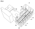
- FIG. 1 is a diagram showing the appearance of the transport system 10. As shown in FIG.
- the transport system 10 includes one or more storage units 200, one or more transport devices 300, one or more machine tools 400, and one or more work stations 500. .
- the storage unit 200 is one of the transfer destinations of the work by the transfer device 300 .
- a plurality of pallets PL can be stored in the storage unit 200 .
- the pallet PL is configured so that a work can be attached.
- the storage unit 200 stores an empty pallet on which no work is mounted, a pallet on which an unprocessed work is mounted, a pallet on which an in-process work is mounted, a pallet on which a processed work is mounted, and the like. .
- the transport device 300 transports the specified pallet PL to the specified location. More specifically, the transport device 300 includes rails 330 and a carriage 331 .
- the carriage 331 is configured to be movable along the rails 330 by, for example, a servomotor 335 (see FIG. 2), which will be described later.
- the truck 331 has a fork portion 333 configured to be drivable in a direction orthogonal to the rails 330 (that is, a direction orthogonal to the running direction of the truck 331).
- the carriage 331 moves along the rail 330 to the position of the pallet PL to be conveyed, and the fork portion 333 is used to place the pallet PL to be conveyed on the carriage 331 .
- the carriage 331 moves along the rails 330 to the specified destination, and uses the fork portion 333 to carry in the pallet PL to be transported to the destination.
- the machine tool 400 is one of the transport destinations of the pallet PL by the transport device 300 .
- the machine tool 400 processes the workpiece attached to the loaded pallet PL according to a pre-designed machining program.
- the pallet PL in the machine tool 400 is transported to the storage section 200 or the work station 500 by the transport device 300 .
- the work station 500 is one of the transport destinations of the pallet PL by the transport device 300 .
- workers perform various operations on the pallet PL that has been brought in. As shown in FIG.
- a worker attaches a work to be processed to the loaded pallet PL, removes a processed work from pallet PL, and the like.
- the worker performs an operation for instructing completion of the work. Based on this, the pallet PL in the work station 500 is transported to the storage section 200 or the machine tool 400 by the transport device 300 .
- FIG. 2 is a diagram showing an example of the device configuration of the transport system 10. As shown in FIG. An example of the device configuration of the transport system 10 will be described with reference to FIG. 2 .
- the transport system 10 includes a control unit 50, remote I/O (Input/Output) units 61-63, a transport device 300, a machine tool 400, and a work station 500.
- control unit 50 remote I/O (Input/Output) units 61-63
- transport device 300 transport device 300
- machine tool 400 machine tool 400
- work station 500 work station 500
- control unit 50 used in this specification means a device that controls the transport system 10.
- the device configuration of the control unit 50 is arbitrary.
- the control section 50 may be composed of a single control unit, or may be composed of a plurality of control units.
- the control unit 50 is composed of a control system 100 and a control panel 150 .
- the control unit 50 may include a CNC 401 that controls the machine tool 400, an operation terminal 550 in the work station 500, or the like.
- the control system 100 is the main computer that controls the transport system 10.
- the control panel 150 controls various industrial equipment for automating the machining process.
- the control board 150 contains PLC151.
- the control system 100 and the PLC 151 are connected to the network NW1.
- Control system 100 and PLC 151 may be connected for communication by wire or by communication by radio.
- EtherNET registered trademark
- the control system 100 sends control instructions to the PLC 151 via the network NW1.
- the control command designates the pallet PL to be transported, the transport destination of the pallet PL, the transport start/stop of the pallet PL, and the like.
- the remote I/O units 61-63 and the PLC 151 are connected to the network NW2.
- NW2 it is preferable to employ a field network that performs periodic communication, in which data arrival time is guaranteed.
- EtherCAT registered trademark
- EtherNet/IP registered trademark
- CC-Link registered trademark
- CompoNet registered trademark
- the transport device 300 includes one or more servo drivers 334 and one or more servo motors 335 .
- a remote I/O unit 61 is installed in the transport device 300 or around the transport device 300 .
- the remote I/O unit 61 mediates data exchange between various drive units (for example, the servo driver 334 ) in the transport device 300 and the PLC 151 .
- the servo driver 334 periodically receives control instructions from the PLC 151 via the remote I/O unit 61, and drives and controls the servo motor 335 according to the control instructions.
- one servomotor 335 drives and controls the carriage 331 (see FIG. 1)
- the other servomotor 335 drives and controls the fork portion 333 (see FIG. 1).
- the servo driver 334 sequentially receives input of the target rotation speed (or target position) from the PLC 151 and controls the servo motor 335 so that it rotates at the target rotation speed. More specifically, the servo driver 334 calculates the actual rotation speed (or actual position) of the servo motor 335 from the feedback signal of the encoder (not shown) for the servo motor 335, and the actual rotation speed is higher than the target rotation speed. If the actual rotation speed is smaller than the target rotation speed, the rotation speed of the servo motor 335 is increased. In this way, the servo driver 334 brings the rotation speed of the servo motor 335 closer to the target rotation speed while sequentially receiving the feedback of the rotation speed of the servo motor 335 . Thereby, the transport device 300 can move the pallet PL to an arbitrary transport destination.
- the machine tool 400 includes a CNC (Computer Numerical Control) 401, a servo driver 411, and a servo motor 412.
- a remote I/O unit 62 is installed in or around the machine tool 400 .
- the remote I/O unit 62 mediates exchange of data between various drive units (for example, CNC 401 ) in the machine tool 400 and the PLC 151 .
- the servo driver 411 receives control instructions from the PLC 151 via the remote I/O unit 62 at regular intervals, and drives and controls the servo motor 412 according to the control instructions.
- the work station 500 includes an operation terminal 550 that receives operations by workers.
- a remote I/O unit 63 is installed in the work station 500 or around the work station 500 .
- the remote I/O unit 63 mediates data exchange between the operation terminal 550 and the PLC 151 .
- the contents of the operator's operation on the operation terminal 550 are sent to the PLC 151 via the remote I/O unit 63 at regular intervals.
- the transport system 10 transports the workpiece to be processed next from the work station 500 to the storage unit 200 .
- the work to be machined next waits until the machine tool 400 finishes machining. After that, when the machine tool 400 finishes machining the workpiece, the next workpiece to be machined is transferred from the storage section 200 to the machine tool 400 .
- the control unit 50 of the transport system 10 acquires the weight (first weight) of the work to be transported from the work station 500 to the storage unit 200, and based on the weight, determines the weight of the work to be transported in the storage unit 200. Decide where to store the The storage destination is determined to be closer to the machine tool 400 as the weight of the work to be transported increases.
- the transfer system 10 can store heavy works near the machine tool 400, improving the transfer efficiency of the work. As a result, work productivity increases.
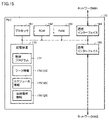
- FIG. 3 is a diagram showing an example of the functional configuration of the control unit 50. As shown in FIG.
- control unit 50 includes a schedule generation unit 152, an acquisition unit 154, and a transport control unit 156 as functional configurations. These functional configurations are implemented in the control system 100 or PLC 151 that constitute the control unit 50 . Alternatively, these functional configurations may be implemented in the operation terminal 550 .
- part of the schedule generation unit 152, the transportation control unit 156, and the acquisition unit 154 are implemented in the control system 100, and the rest of the functional configuration is implemented in the PLC 151.
- schedule generator 152 , transport controller 156 , and acquirer 154 are all implemented in control system 100 .
- schedule generator 152 , transport controller 156 , and acquirer 154 are all implemented in PLC 151 .
- the schedule generator 152 generates the machining schedule 125 shown in FIG. 6 based on the machining settings 123 shown in FIG. 4 and the workpiece information 124 shown in FIG.
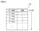
- FIG. 4 is a diagram showing an example of the data structure of the processing settings 123.
- the operator registers the work to be processed in advance by registering the processing setting 123 .
- the processing settings 123 are registered by the operator, for example, in the control system 100 described above or the operation terminal 550 described above.
- the contents registered by the operator include, for example, identification information of the work to be processed (work name, work ID, etc.), the number of works to be processed, the order of processing the works, and the like.
- the machining settings 123 include a machining task for one workpiece WA with a machining time of 15 minutes, a machining task for one workpiece WB with a machining time of 35 minutes, and a machining time of 25 minutes. It includes machining tasks for two workpieces WC and machining tasks for three workpieces WD whose machining time is 35 minutes.
- FIG. 5 is a diagram showing an example of the data structure of the work information 124.
- the workpiece information 124 includes a machining program for machining the workpiece, the weight of the workpiece, the machining time required for machining the workpiece, and other information related to machining the workpiece, for each workpiece identification information. stipulated.
- the machining program defined in the workpiece information 124 is registered by the operator in, for example, the control system 100 described above, the machine tool 400 described above, or the operation terminal 550 described above. Any method can be used to generate the machining program. As an example, some machine tools 400 have a function of automatically generating a machining program in response to interactive questions from the operator. A machining program is generated by the function, for example. Alternatively, the machining program may be designed by an operator writing program code.
- the weight specified in the workpiece information 124 may be set in advance by the user, or may be registered when the machining program is designed. As an example, the weight is input at the operation terminal 550 . The weight indicates the weight of the workpiece before starting processing.
- the machining time specified in the workpiece information 124 is, for example, input in advance by the operator. Alternatively, the machining time may be calculated from the past machining performance of each workpiece.
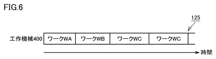
- the schedule generation unit 152 refers to the work information 124 and specifies the machining time for each work specified in the machining settings 123 . 6 based on the specified machining time, the number of workpieces defined in the machining settings 123, and the machining order of the workpieces defined in the machining settings 123.
- a processing schedule 125 is generated.
- FIG. 6 is a diagram showing a processing schedule 125 as an example.
- the machining schedule 125 defines machining tasks for workpieces in each of the machine tools 400 .
- the processing schedule 125 generated by the schedule generator 152 may be stored in the storage device of the transport system 10 or may be output to the transport controller 156 .
- the acquisition unit 154 acquires the weight of the work to be transported.
- the weight of the work to be transported is acquired from the work information 124, for example.
- the work information 124 defines the weights of various works.
- the acquisition unit 154 acquires the weight corresponding to the type of work from the work information 124 based on the type of work to be transported acquired from the transport control unit 156 .
- the acquired work weight is output to the transport control unit 156 .
- the method of obtaining the weight of the workpiece is not limited to the above method. Workpiece weight can be obtained in a variety of ways.
- the acquisition unit 154 acquires the weight of the work to be transported from a weight sensor (not shown).
- the weight sensor is provided, for example, on each pallet.
- the weight sensor detects the weight of the work based on the work being attached to the pallet.
- the weight of the work is transmitted to the control unit 50, for example.
- the acquisition unit 154 measures the weight of the work to be transported using a camera (not shown).
- the camera is provided, for example, in work station 500 . Based on the work being attached in the work station 500, the acquisition unit 154 sends a photographing instruction to the camera. Thereby, the acquisition unit 154 acquires an image representing the work to be transported.
- Various image processing can be used for the method of detecting the weight of the work from the image.
- the weight of a workpiece is measured using a trained model.
- a trained model is generated in advance by a learning process using a learning data set.
- the learning data set includes a plurality of learning images showing workpieces. Each learning image is associated with a label indicating the weight of the workpiece.
- the internal parameters of the trained model are optimized in advance by learning processing using such a learning data set.
- CNN convolutional neural network
- FCN full-layer convolutional neural network
- support vector machine etc.
- the acquisition unit 154 inputs the image obtained from the camera to the trained model.
- the learned model outputs the weight of the work shown in the image when the input of the image is received. Thereby, the acquisition unit 154 acquires the weight of the work to be transported.
- the method of estimating the work weight using an image is not limited to the above-described method using a trained model, and rule-based image processing may be employed.
- the acquisition unit 154 may estimate the weight of the workpiece from the motor load applied to the transport device 300. More specifically, the greater the motor load, the greater the weight of the workpiece.
- the acquisition unit 154 for example, based on the magnitude of the current value, the servomotor 335 Detects the motor load applied to If the servomotor 335 is a three-phase AC motor, the servomotor 335 is controlled via an inverter (not shown). In this case, the torque of the servomotor 335 is controlled, for example, based on the following formula (1).
- T K ⁇ (V/f) ⁇ I (1)
- T shown in equation (1) indicates the torque of the servomotor 335 (motor load).
- K is a constant.
- V indicates the output voltage value to the inverter.
- f indicates the output frequency of the inverter.
- I indicates the output current value to the inverter.
- K ⁇ (V/f) is a constant value up to a constant frequency (eg, 60 Fz). That is, the motor load changes according to the output current value "I" of the inverter.
- the acquisition unit 154 estimates the weight of the work to be transported based on the output current value "I" of the inverter. More specifically, the correlation between the magnitude of the output current value "I" and the weight of the workpiece to be transported is determined in advance.
- the correlation may be defined in a table format in which the weight of the workpiece is associated with each output current value, or may be defined by a correlation formula in which the output current value is the explanatory variable and the weight of the workpiece is the objective variable. .
- FIG. 7 is a diagram showing an example of a work transfer process from the storage unit 200 to the machine tool 400. As shown in FIG.
- the transport control unit 156 refers to the processing schedule 125 described above and recognizes the work WA as the first processing target. Based on this, the transport control unit 156 starts transporting the empty pallet from the storage unit 200 to the work station 500 .
- the pallet to be transported at this time may be randomly determined from among empty pallets, or may be determined from pallets designated in advance.
- the storage unit 200 has pallet storage locations P1 to P10, and an empty pallet PL4 is determined as a transport target.
- the worker attaches the work WA to the pallet PL4.
- the operator performs a transport start operation for the pallet PL4.
- the transport start operation is implemented by pressing a transport start button provided in the work station 500 .
- the transport control unit 156 transports the pallet PL4 on which the work WA is attached to the machine tool 400.
- machine tool 400 starts machining workpiece WA.
- FIG. 8 is a diagram showing the process of transporting the work WB from the work station 500 to the storage section 200 when the work WB is light in weight.
- the transfer control unit 156 refers to the above-described processing schedule 125 and recognizes the work WB as the second processing target based on the completion of the transfer of the work WA as the first processing target. At this time, since the machine tool 400 is processing the work WA, the transfer control unit 156 needs to temporarily store the work WB in the storage unit 200 until the machine tool 400 becomes empty. In this case, the transport control unit 156 acquires the weight (first weight) of the work WB from the above work information 124 (see FIG. 5), and determines the storage destination for the work WB based on the weight. At that time, the storage destination is determined so as to be closer to the machine tool 400 as the weight of the work WB is heavier.
- the transport control unit 156 determines the storage destination of the work WB based on the storage location information 126 shown in FIG.
- FIG. 9 is a diagram showing an example of the data structure of the storage location information 126. As shown in FIG.
- the storage location information 126 includes, for each storage location in the storage unit 200, the weight range of the work, the coordinate values of the storage location, the presence or absence of a pallet in the storage location or identification information of the pallet, the presence or absence of the work in the storage location, or the identification information of the pallet. identification information, etc.
- the storage location P1 is associated with a weight range ⁇ w1.
- a weight range ⁇ w2 is associated with the storage location P2.
- the upper limit value of the weight range ⁇ w2 is smaller than the lower limit value of the weight range ⁇ w1.
- a weight range ⁇ w3 is associated with the storage location P3.
- the upper limit of weight range ⁇ w3 is smaller than the lower limit of weight range ⁇ w2.
- a weight range ⁇ w4 is associated with the storage location P4.
- the upper limit value of the weight range ⁇ w4 is smaller than the lower limit value of the weight range ⁇ w3.
- a weight range ⁇ w5 is associated with the storage location P5.
- the upper limit of weight range ⁇ w5 is smaller than the lower limit of weight range ⁇ w4.
- a weight range ⁇ w6 is associated with the storage location P6.
- the upper limit of weight range ⁇ w6 is smaller than the lower limit of weight range ⁇ w5.
- a weight range ⁇ w7 is associated with the storage location P7.
- the upper limit of weight range ⁇ w7 is smaller than the lower limit of weight range ⁇ w6.
- a weight range ⁇ w8 is associated with the storage location P8.
- the upper limit of weight range ⁇ w8 is smaller than the lower limit of weight range ⁇ w7.
- a weight range ⁇ w9 is associated with the storage location P9.
- the upper limit value of the weight range ⁇ w9 is smaller than the lower limit value of the weight range ⁇ w8.
- a weight range ⁇ w10 is associated with the storage location P10.
- the upper limit of weight range ⁇ w10 is smaller than the lower limit of weight range ⁇ w9.
- the transport control unit 156 refers to the storage location information 126 to identify the weight range to which the weight of the work WB belongs, and determines the storage location associated with the weight range as the storage destination of the work WB. In the example of FIG. 8, the storage location P9 is determined as the storage location for the light work WB.
- the transport control unit 156 transports the empty pallet PL9 in the storage location P9 from the storage unit 200 to the work station 500. After that, the worker attaches the work WB to the pallet PL9. When the work WB mounting operation is completed, the operator performs the transportation start operation of the pallet PL9. After that, the transport control unit 156 transports the pallet PL9 from the work station 500 to the storage location PL9. As a result, the light work WB is stored in the storage location P9 far from the machine tool 400. As shown in FIG.
- FIG. 10 is a diagram showing the process of transporting the work WB from the work station 500 to the storage section 200 when the work WB is heavy.
- the transport control unit 156 refers to the storage location information 126 to identify the weight range to which the weight of the work WB belongs, and designates the storage location associated with the weight range as the storage destination of the work WB. decide.
- the storage location P1 is determined as the storage location for the heavy work WB.
- the transport control unit 156 transports the empty pallet PL1 in the storage location P1 from the storage unit 200 to the work station 500. After that, the worker attaches the work WB to the pallet PL1. When the work WB mounting operation is completed, the operator performs the transportation start operation of the pallet PL1. After that, the transport control unit 156 transports the pallet PL1 from the work station 500 to the storage location PL1. As a result, the heavy work WB is stored in the storage location P ⁇ b>1 near the machine tool 400 .
- 11A and 11B are diagrams showing the transfer process of the work WC from the work station 500 to the storage unit 200 when the weight of the work WC is lighter than the weight of the work WB.
- the transfer control unit 156 Upon completion of the transfer of the work WB, which is the second processing target, the transfer control unit 156 refers to the above-described processing schedule 125 and recognizes the work WC as the third processing target. At this time, since the machine tool 400 is processing the work WA, the transfer control unit 156 needs to temporarily store the work WC in the storage unit 200 until the machine tool 400 becomes available. In this case, the transport control unit 156 acquires the weight of the work WC from the work information 124 described above, and determines the storage destination for the work WC based on the weight.
- the transport control unit 156 determines the storage destination of the work WC based on the weight of the stored works. .
- the transfer process for the work WC will be described on the assumption that the work WB is stored in the storage location P5.
- the transport control unit 156 refers to the work information 124 described above to obtain the weight of the stored work WB and the weight of the work WC to be transported. After that, the transport control unit 156 determines the storage location of the work WC by comparing the weight of the work WB that has already been stored and the weight of the work WC to be transported.
- the transport control unit 156 moves the work WB to the storage location P5.
- the storage destination of the work WC is determined so as to be farther from the machine tool 400 than the work WC.
- the storage location of the work WC is determined from storage locations P6 to P10 that are farther from the machine tool 400 than the storage location P5 of the work WB.
- FIG. 12 is a diagram showing the transfer process of the work WC from the work station 500 to the storage unit 200 when the work WC is heavier than the work WB.
- the transport control unit 156 moves the work WB to the storage location P5.
- the storage destination of the work WC is determined so as to be closer to the machine tool 400 than the machine tool 400 is. In this case, the storage location of the work WC is determined from storage locations P1 to P4 closer to the machine tool 400 than the storage location P5 of the work WB.
- the storage destination of the work to be transported does not necessarily have to be determined based on the relationship between the storage location of the work and the weight of the work. It may be determined based on the weight of the finished workpiece. This eliminates the need to predefine the relationship between the work storage location and the weight of the work, and the transport control unit 156 can flexibly and efficiently transport the work.
- the timing of determining the storage destination is arbitrary. be.
- the storage destination may be determined after the work mounting operation at work station 500 is completed. In this case, the weight of the workpiece does not necessarily have to be predefined.
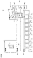
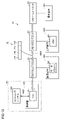
- FIG. 13A and 13B are conceptual diagrams schematically showing cooperative relationships among various devices that constitute the transport system 10.
- control system 100 and the PLC 151 are connected to the network NW1 such as EtherNET.
- NW1 such as EtherNET.
- Remote I/O units 61-63 and PLC 151 are connected to network NW2, which is a field network.
- a frame 72 is transmitted to the network NW2.
- the frame 72 circulates on the network NW2 every predetermined control cycle.
- Remote I/O units 61 to 63 and PLC 151 share various data via frame 72 .
- the frame 72 includes, for example, a data area 71A for the PLC 151, a data area 71B for the transfer device 300 connected to the remote I/O unit 61, and data for the machine tool 400 connected to the remote I/O unit 62. It has an area 71C and a data area 71D for the operation terminal 550 connected to the remote I/O unit 63.
- a data area 71A of the frame 72 is an area in which the PLC 151 writes various data.
- the transport instruction includes the transport destination of the pallet PL.
- the transport destination is, for example, an identification number indicating a storage location in pallet storage unit 200 (for example, an ID (Identification) indicating a storage location) or an identification number for identifying machine tool 400 (for example, machine tool ID ), etc.
- Various data written in the data area 71A by the PLC 151 can be referred to by various devices connected to the network NW2.
- a data area 71B of the frame 72 is an area in which the remote I/O unit 61 writes various data regarding the transport device 300 .
- the various data written in the data area 71B are referred to by various devices connected to the network NW2.
- a data area 71C of the frame 72 is an area in which the remote I/O unit 62 writes various data related to the machine tool 400.
- the various data written in the data area 71C are referred to by various devices connected to the network NW2.
- the data area 71D of the frame 72 is, for example, an area in which the remote I/O unit 63 writes operation details for the operation terminal 550. As an example, in the data area 71D of the frame 72, the selection result of permitting or denying transportation of the pallet from the work station 500 is written.
- FIG. 14 is a schematic diagram showing an example of the hardware configuration of the control system 100. As shown in FIG.
- the control system 100 includes a processor 101 , a ROM (Read Only Memory) 102 , a RAM (Random Access Memory) 103 , a communication interface 104 , a display interface 105 , an input interface 107 and a storage device 120 . These components are connected to bus 110 .
- the processor 101 is composed of, for example, at least one integrated circuit.
- Integrated circuits include, for example, at least one CPU (Central Processing Unit), at least one GPU (Graphics Processing Unit), at least one ASIC (Application Specific Integrated Circuit), at least one FPGA (Field Programmable Gate Array), or It can be configured by a combination of
- the processor 101 controls the operation of the control system 100 by executing various programs such as the control program 122 and operating system.
- the control program 122 is a program related to work transfer control.
- the processor 101 reads the control program 122 from the storage device 120 or the ROM 102 to the RAM 103 based on the acceptance of the instruction to execute the control program 122 .
- the RAM 103 functions as a working memory and temporarily stores various data necessary for executing the control program 122 .
- a LAN Local Area Network
- an antenna etc. are connected to the communication interface 104 .
- Control system 100 is connected to network NW1 via communication interface 104 . Thereby, the control system 100 exchanges data with external devices connected to the network NW1.
- the external device includes, for example, the control panel 150 and a server (not shown).
- the control system 100 may be configured so that the control program 122 can be downloaded from the external device.
- a display 106 is connected to the display interface 105 .
- Display interface 105 sends an image signal for displaying an image to display 106 according to a command from processor 101 or the like.
- the display 106 is, for example, a liquid crystal display, an organic EL (Electro Luminescence) display, or other display device. Note that the display 106 may be configured integrally with the control system 100 or may be configured separately from the control system 100 .
- An input device 108 is connected to the input interface 107 .
- Input device 108 is, for example, a mouse, keyboard, touch panel, or other device capable of receiving user operations. Note that the input device 108 may be configured integrally with the control system 100 or may be configured separately from the control system 100 .
- the storage device 120 is, for example, a storage medium such as a hard disk or flash memory.
- the storage device 120 stores the control program 122, the above machining settings 123, the above workpiece information 124, the above machining schedule 125, the above storage location information 126, and the like.
- the storage location of various data stored in the storage device 120 is not limited to the storage device 120, but may be a storage area of the processor 101 (for example, cache memory, etc.), ROM 102, RAM 103, external devices (for example, PLC 151 or external server), etc. may be stored in
- the control program 122 may be provided as a part of an arbitrary program, not as a standalone program. In this case, the transport control process by the control program 122 is implemented in cooperation with any program. Even a program that does not include such a part of modules does not deviate from the gist of control program 122 according to the present embodiment. Furthermore, some or all of the functions provided by control program 122 may be implemented by dedicated hardware. Furthermore, the control system 100 may be configured as a so-called cloud service in which at least one server executes part of the processing of the control program 122 .
- FIG. 15 is a block diagram showing the main hardware configuration of the PLC 151. As shown in FIG. 15
- the PLC 151 includes a processor 161 , a ROM (Read Only Memory) 162 , a RAM (Random Access Memory) 163 , communication interfaces 164 and 165 and a storage device 170 .
- the processor 161 is composed of at least one integrated circuit.
- An integrated circuit is composed of, for example, at least one CPU, at least one MPU (Micro Processing Unit), at least one ASIC, at least one FPGA, or a combination thereof.
- the processor 161 controls the operations of the transport device 300 and the machine tool 400 by executing various programs such as the control program 172 .
- the processor 161 reads the control program 172 from the storage device 170 to the ROM 162 based on the acceptance of the instruction to execute the control program 172 .
- the RAM 163 functions as a working memory and temporarily stores various data necessary for executing the control program 172 .
- a LAN, an antenna, and the like are connected to the communication interface 164 .
- PLC 151 is connected to network NW1 via communication interface 164 . Thereby, the PLC 151 exchanges data with an external device connected to the network NW1.
- the external device includes, for example, the control system 100 and a server (not shown).
- the communication interface 165 is an interface for connecting to the network NW2, which is a field network.
- PLC 151 exchanges data with external devices connected to network NW2 via communication interface 165 .
- the external device includes, for example, remote I/O units 61-63.
- the storage device 170 is, for example, a storage medium such as a hard disk or flash memory.
- the storage device 170 stores a control program 172, work information 174, a machining schedule 175, storage location information 176, and the like.
- Work information 174 corresponds to work information 124 received from control system 100 described above.
- Processing schedule 175 corresponds to processing schedule 125 received from control system 100 described above.
- Storage location information 176 corresponds to storage location information 126 received from control system 100 described above.
- the storage location of various data stored in the storage device 170 is not limited to the storage device 170, but is stored in the storage area of the processor 161 (for example, cache area), ROM 162, RAM 163, external equipment (for example, server), and the like. may be
- the control program 172 may be provided as a part of an arbitrary program, not as a standalone program. In this case, the control processing according to this embodiment is implemented in cooperation with any program. Even a program that does not include such a part of modules does not deviate from the gist of control program 172 according to the present embodiment. Furthermore, some or all of the functions provided by control program 172 may be implemented by dedicated hardware. Furthermore, the PLC 151 may be configured as a so-called cloud service in which at least one server executes part of the processing of the control program 172 .
- FIG. 16 is a block diagram showing the main hardware configuration of machine tool 400. As shown in FIG.
- Machine tool 400 includes CNC 401, ROM 402, RAM 403, fieldbus controller 404, display interface 405, input interface 409, servo drivers 411A to 411D, servo motors 412A to 412D, encoders 413A to 413D, It includes ball screws 414A, 414B and a spindle 415 for mounting tools. These devices are connected via a bus (not shown).
- the CNC 401 is composed of at least one integrated circuit.
- An integrated circuit is composed of, for example, at least one CPU, at least one MPU, at least one ASIC, at least one FPGA, or a combination thereof.
- the CNC 401 controls the operation of the CNC 400 by executing various programs such as the machining program 422.
- CNC401 reads the machining program 422 from the memory
- the RAM 403 functions as a working memory and temporarily stores various data necessary for executing the machining program 422 .
- the fieldbus controller 404 is an interface for realizing communication with the PLC 151 via the remote I/O unit 62. CNC 400 exchanges data with PLC 151 via fieldbus controller 404 .
- the display interface 405 is connected to a display device such as the display 430, and transmits an image signal for displaying an image on the display 430 according to a command from the CNC 401 or the like.
- Display 430 is, for example, a liquid crystal display, an organic EL display, or another display device.
- the input interface 409 can be connected to the input device 431 .
- the input device 431 is, for example, a mouse, keyboard, touch panel, or other input equipment capable of receiving user operations.
- the CNC 400 controls the servo driver 411A according to the machining program 422.
- the servo driver 411A sequentially receives input of the target rotation speed (or target position) from the CNC 401, controls the servo motor 412A so that the servo motor 412A rotates at the target rotation speed, and moves the workpiece installation table (not shown). Drive in the X-axis direction.
- the servo driver 411A calculates the actual rotation speed (or actual position) of the servo motor 412A from the feedback signal of the encoder 413A, and if the actual rotation speed is smaller than the target rotation speed, the servo motor 412A is increased, and if the actual rotation speed is greater than the target rotation speed, the rotation speed of the servomotor 412A is decreased. In this way, the servo driver 411A brings the rotation speed of the servomotor 412A closer to the target rotation speed while sequentially receiving the feedback of the rotation speed of the servomotor 412A.
- the servo driver 411A moves the workpiece mounting base connected to the ball screw 414A in the X-axis direction to move the workpiece mounting base to an arbitrary position in the X-axis direction.
- the servo driver 411B moves the workpiece mounting base connected to the ball screw 414B in the Y-axis direction according to the control command from the CNC 400, and moves the workpiece mounting base to any position in the Y-axis direction.
- the servo driver 411C moves the main shaft 415 in the Z-axis direction according to the control command from the CNC 400, and moves the main shaft 415 to any position in the Z-axis direction.
- the servo driver 411D controls the rotation speed of the main shaft 415 according to control commands from the CNC 400.
- the storage device 420 is, for example, a storage medium such as a hard disk or flash memory.
- the storage device 420 stores a machining program 422 and the like.
- the storage location of the machining program 422 is not limited to the storage device 420, and may be stored in a storage area of the CNC 401 (for example, cache area), ROM 402, RAM 403, external equipment (for example, server), or the like.
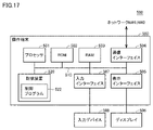
- FIG. 17 is a schematic diagram showing an example of the hardware configuration of the operation terminal 550. As shown in FIG.
- the operation terminal 550 includes a processor 501 , a ROM 502 , a RAM 503 , a communication interface 504 , a display interface 505 , an input interface 507 and a storage device 520 . These components are connected to bus 510 .
- the processor 501 is composed of, for example, at least one integrated circuit.
- An integrated circuit may be comprised of, for example, at least one CPU, at least one GPU, at least one ASIC, at least one FPGA, or combinations thereof.
- the processor 501 controls the operation of the operation terminal 550 by executing various programs such as the control program 522 and operating system.
- the processor 501 reads the control program 522 from the storage device 520 or the ROM 502 to the RAM 503 based on the acceptance of the instruction to execute the control program 522 .
- the RAM 503 functions as a working memory and temporarily stores various data necessary for executing the control program 522 .
- a LAN, an antenna, and the like are connected to the communication interface 504 .
- Operation terminal 550 is connected to networks NW1 and NW2 via communication interface 504 . Thereby, the operation terminal 550 exchanges data with external devices connected to the networks NW1 and NW2.
- the external device includes, for example, the control panel 150 and a server (not shown).
- the operation terminal 550 may be configured so that the control program 522 can be downloaded from the external device.
- a display 506 is connected to the display interface 505 .
- Display interface 505 sends an image signal for displaying an image to display 506 in accordance with a command from processor 501 or the like.
- a display 506 displays a selection screen or the like for accepting or rejecting forced transportation of the pallet being worked on the work station 500 .
- Display 506 is, for example, a liquid crystal display, organic EL display, or other display device. Note that the display 506 may be configured integrally with the operation terminal 550 or may be configured separately from the operation terminal 550 .
- An input device 508 is connected to the input interface 507 .
- Input device 508 is, for example, a mouse, keyboard, touch panel, or other device capable of receiving user operations. Note that the input device 508 may be configured integrally with the operation terminal 550 or may be configured separately from the operation terminal 550 .
- the storage device 520 is, for example, a storage medium such as a hard disk or flash memory.
- the storage device 520 stores a control program 522 and the like.
- the storage location of the control program 522 and the like is not limited to the storage device 520, and may be stored in a storage area of the processor 501 (eg, cache memory, etc.), ROM 502, RAM 503, external device (eg, server), or the like.
- the control program 522 may be provided as a part of an arbitrary program, not as a standalone program. In this case, control processing by the control program 522 is implemented in cooperation with an arbitrary program. Even a program that does not include such a part of modules does not deviate from the gist of control program 522 according to the present embodiment. Furthermore, some or all of the functions provided by control program 522 may be implemented by dedicated hardware. Furthermore, the operation terminal 550 may be configured in the form of a so-called cloud service in which at least one server executes part of the processing of the control program 522 .
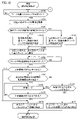
- FIG. 18 is a flow chart showing part of the transport process executed by the processor 161. As shown in FIG.
- step S110 the processor 161 determines whether or not an instruction to carry the work into the work station 500 has been received.
- the carry-in instruction is issued, for example, by pressing a carry-in start button provided in work station 500 .
- processor 161 determines that an instruction to carry a workpiece into work station 500 has been received (YES in step S110)
- processor 161 switches control to step S112. Otherwise (NO in step S110), processor 161 executes the process of step S110 again.
- step S112 the processor 161 functions as the acquisition unit 154 (see FIG. 3) described above, refers to the work information 124 (see FIG. 5) described above, and acquires the weight of the work to be transported.
- step S120 the processor 161 refers to the storage location information 126 (see FIG. 9) described above and determines whether or not there is another work in the storage unit 200 that is different from the work to be transported.
- processor 161 determines that there is another stored work in storage unit 200 (YES in step S120)
- processor 161 switches control to step S124. Otherwise (NO in step S120), processor 161 switches control to step S122.
- step S122 the processor 161 functions as the above-described transport control unit 156 (see FIG. 3), and based on the storage location information 126, identifies the weight range to which the weight of the work acquired in step S112 belongs. Then, the processor 161 determines the storage location associated with the weight range as the storage destination of the work to be transported. At this time, the storage destination is determined so as to be closer to the machine tool 400 as the weight of the work to be transferred is heavier.
- step S124 the processor 161 functions as the above-described transport control unit 156, and determines the storage destination of the work to be transported based on the weight of the work already stored in the storage unit 200. More specifically, when the weight of the work to be transported is lighter than the weight of the stored work, the storage destination of the work to be transported is farther from the machine tool 400 than the position of the stored work. On the other hand, when the weight of the work to be transported is heavier than the weight of the stored work, the storage destination of the work to be transported is closer to the machine tool 400 than the position of the stored work. At this time, the storage destination is determined from the storage location of the empty pallet.
- the processor 161 functions as the transport control unit 156 described above, and transports the empty pallet at the storage destination determined at step S122 or step S124 to the work station 500.
- step S130 the processor 161 determines whether or not a pallet transport start operation has been accepted.
- the transportation start operation is received, for example, at the operation terminal 550 described above.
- processor 161 determines that a pallet transport start operation has been received (YES in step S130)
- processor 161 switches control to step S140. Otherwise (NO in step S130), processor 161 executes the process of step S130 again.
- step S140 the processor 161 determines whether or not the machine tool 400 is not working. Whether or not machine tool 400 is not performing machining is determined, for example, based on whether or not a machining program is being executed. When processor 161 determines that machine tool 400 is not machining (YES in step S140), it switches control to step S172. Otherwise (NO in step S140), processor 161 switches control to step S150.
- step S150 the processor 161 determines whether the time until the start of the next machining is within a predetermined time. For example, it is determined based on the above-described processing schedule 125 whether the time until the start of the next processing is within the predetermined time. The length of the predetermined time may be set in advance or may be arbitrarily set by the user.
- the processor 161 determines that the time until the start of the next machining is within the predetermined time (YES in step S150)
- the control is switched to step S152. Otherwise (NO in step S150), processor 161 switches control to step S160.
- step S152 the processor 161 sets the operation mode of the transport device 300 to the standby mode, and stops driving the transport device 300.
- the processor 161 determines whether or not there is a pallet that requires setup work in the storage unit 200. Whether or not the pallet is in storage unit 200 is determined based on, for example, processing schedule 125 described above and storage location information 126 described above.
- the setup work includes, for example, the work of mounting a work to be processed on a pallet and the work of removing a machined work from the pallet.
- step S170 the processor 161 determines whether or not the machine tool 400 is not working. Whether or not machine tool 400 is not performing machining is determined, for example, based on whether or not a machining program is being executed. When processor 161 determines that machine tool 400 is not machining (YES in step S170), it switches control to step S172. Otherwise (NO in step S170), processor 161 returns control to step S152.
- the processor 161 functions as the above-described transport control unit 156 and transports the pallet with the work attached at the work station 500 to the machine tool 400 .
- the processor 161 functions as the transport control unit 156 described above, and transports the pallet on which the work is attached at the work station 500 to the storage destination determined at step S122 or step S124. In this way, the processor 161 transports the work to be transported to the storage destination while the machine tool 400 is processing a work different from the work to be transported.
- the processor 161 uses the processing waiting time to transport each work to a storage destination according to its weight, thereby improving the efficiency of transporting the work.
- the timing of determining the storage destination is arbitrary. be.
- the storage destination may be determined after the work mounting operation at work station 500 is completed.
- the storage destination of the work to be transported was uniquely determined based on the storage location information 126. 11 and 12, the storage destination of the work in the storage unit 200 is determined based on the weight of the stored work.
- the storage location of the storage unit 200 is divided into a plurality of storage areas in advance, and the transport system 10 transports the work to a storage area according to the weight of the work to be transported. .
- FIG. 19 is a diagram showing the transfer process of the work WB from the work station 500 to the storage area AR1.
- the storage section 200 is divided into a storage area AR1 (first storage area) and a storage area AR2 (second storage area).
- the storage area AR1 includes workpiece storage locations P1 to P5.
- the storage area AR2 includes workpiece storage locations P6 to P10.
- Storage area AR1 is closer to machine tool 400 than storage area AR2.
- the control unit 50 of the transport system 10 determines the storage destination from within the storage area AR1 closer to the machine tool 400 when the weight of the work WB to be transported is heavier than a predetermined weight.
- the storage location is determined from an empty storage location closer to machine tool 400 .
- the storage location may be randomly determined from empty storage locations P1 to P5.
- FIG. 20 is a diagram showing the transfer process of the work WB from the work station 500 to the storage area AR2.
- the control unit 50 of the transfer system 10 determines the storage destination from within the storage area AR2 farther from the machine tool 400 when the weight of the work WB to be transported is lighter than a predetermined weight. do.
- the storage location is determined from an empty storage location away from machine tool 400 .
- the storage location may be randomly determined from empty storage locations P6 to P10.
- the storage area of the storage unit 200 is roughly divided according to the weight of the workpiece, which simplifies the design of the program.
- FIGS. 19 and 20 describe an example in which the storage section 200 is divided into two storage areas AR1 and AR2, the number of divisions of the storage section 200 is not limited to two.
- the storage unit 200 may be divided into three or more storage areas.
- the number of storage locations included in each storage area does not need to be the same. Furthermore, the number of storage locations included in each storage area may be fixed, or may be dynamically changed according to the work storage rate in each storage area. As an example, the transport system 10 may appropriately adjust the number of storage locations included in each storage area so that the difference in work storage rate in each storage area is minimized.
- the storage unit 200 is configured in a single stage.
- the storage section 200 is configured with two or more stages.
- FIG. 21 is a diagram showing a storage section 200 according to a modification.
- the storage section 200 is composed of two stages ST1 and ST2.
- Stage ST2 (second stage) is higher than stage ST1 (first stage).
- Stage ST1 includes work storage locations P1 to P10.
- Stage ST2 includes workpiece storage locations P11 to P20.
- the work transfer time in the vertical direction (gravitational direction) is longer than the work transfer time in the horizontal direction. Therefore, when the storage unit 200 is configured with a plurality of stages, the transport system 10 determines the storage destination of the work to be transported in order from the bottom stage of the storage unit 200 . That is, the transport system 10 prioritizes the distance from the machine tool 400 to the storage location in the vertical direction over the distance from the machine tool 400 to the storage location in the horizontal direction as a criterion for determining the storage location.
- control unit 50 of the transport system 10 determines the storage destination from within the stage ST1 based on the weight of the work to be transported when there is a vacancy in the stage ST1. At this time, the storage destination is determined from within the stage ST1 such that the heavier the work, the closer it is to the machine tool 400 .
- the method of determining the storage destination within the same row is as described above.
- stage ST2 determines the storage destination within stage ST2 based on the weight of the work to be transported. At this time, the storage destination is determined from within the stage ST2 such that the heavier the work, the closer it is to the machine tool 400 .
- the method of determining the storage destination within the same row is as described above.
- the storage destination of the work to be transported was determined based on the weight of the work.
- the transport system 10 according to the present modification is configured to be able to accept designation of a work whose processing order is prioritized over other works (hereinafter also referred to as "priority work").
- the designation of the priority work is accepted, for example, by the operation terminal 550 (operation panel) described above.
- control unit 50 of the transport system 10 receives the designation of the priority work, it determines the storage destination in the storage unit 200 regardless of the weight of the priority work. At this time, the control unit 50 determines the storage location closer to the machine tool 400 among the storage locations P1 to P10 in the storage unit 200 as the storage destination of the priority work. Thereby, the transport system 10 can shorten the transport time of the priority work.
Landscapes
- Engineering & Computer Science (AREA)
- Mechanical Engineering (AREA)
- General Engineering & Computer Science (AREA)
- Manufacturing & Machinery (AREA)
- Quality & Reliability (AREA)
- Physics & Mathematics (AREA)
- General Physics & Mathematics (AREA)
- Automation & Control Theory (AREA)
- General Factory Administration (AREA)
- Multi-Process Working Machines And Systems (AREA)
- Feeding Of Workpieces (AREA)
Abstract
Description
図1を参照して、搬送システム10について説明する。図1は、搬送システム10の外観を示す図である。
図2は、搬送システム10の装置構成の一例を示す図である。図2を参照して、搬送システム10の装置構成の一例について説明する。
次に、上述の図1を参照して、搬送システム10によるワークの搬送制御について説明する。
図3~図12を参照して、上述の制御部50(図2参照)の機能について説明する。図3は、制御部50の機能構成の一例を示す図である。
まず、図4~図6を参照して、図3に示されるスケジュール生成部152の機能について説明する。
次に、上述の図5を参照して、図3に示される取得部154の機能について説明する。
式(1)に示される「T」は、サーボモータ335のトルク(モータ負荷)を示す。「K」は、定数である。「V」は、インバータへの出力電圧値を示す。「f」は、インバータの出力周波数を示す。「I」は、インバータへの出力電流値を示す。「K×(V/f)」は、一定周波数(たとえば、60Fz)までは一定値となる。すなわち、モータ負荷は、インバータの出力電流値「I」に応じて変わる。
次に、図3に示される搬送制御部156の機能について説明する。まず、図7を参照して、加工スケジュール125に規定される1つ目のワークWAの搬送過程について説明する。図7は、収納部200から工作機械400へのワークの搬送過程の一例を示す図である。
図13を参照して、搬送システム10を構成する各種機器間でのデータの共有方法について説明する。図13は、搬送システム10を構成する各種機器の協働関係を概略的に示す概念図である。
図14を参照して、コントロールシステム100のハードウェア構成について説明する。図14は、コントロールシステム100のハードウェア構成の一例を示す模式図である。
図15を参照して、PLC151のハードウェア構成の一例について説明する。図15は、PLC151の主要なハードウェア構成を示すブロック図である。
図16を参照して、工作機械400のハードウェア構成の一例について説明する。図16は、工作機械400の主要なハードウェア構成を示すブロック図である。
図17を参照して、作業ステーション500に設置されている操作端末550のハードウェア構成について説明する。図17は、操作端末550のハードウェア構成の一例を示す模式図である。
図18を参照して、PLC151のプロセッサ161の制御フローについて説明する。図18は、プロセッサ161が実行する搬送処理の一部を表わすフローチャートである。
次に、図19および図20を参照して、作業ステーション500から収納部200へのワークの搬送方法における変形例1について説明する。
次に、図21を参照して、作業ステーション500から収納部200へのワークの搬送方法における変形例2について説明する。
次に、作業ステーション500から収納部200へのワークの搬送方法における変形例3について説明する。
Claims (7)
- ワークの搬送システムであって、
加工対象のワークを搬送するための搬送装置と、
前記搬送装置によるワークの搬送先の1つであり、複数のワークを収納することが可能な収納部と、
前記搬送装置によるワークの搬送先の1つであり、作業者がワークに対する作業を行うための作業ステーションと、
前記搬送装置によるワークの搬送先の1つであり、ワークを加工するための工作機械と、
前記搬送システムを制御するための制御部と、
他のワークよりも加工順を優先するワークの指定を受け付けることが可能な操作盤とを備え、
前記制御部は、
前記作業ステーションから前記収納部への搬送対象のワークの第1重量を取得する処理と、
前記第1重量に基づいて、前記搬送対象のワークについて前記収納部内の収納先を決定する処理とを実行し、前記収納先は、前記第1重量が重いほど前記工作機械に近くなるように決定され、
前記指定を受け付けた場合、前記優先するワークの重量に関わらず、前記収納部内の収納先を決定する処理をさらに実行し、当該収納先は、前記収納部内の収納場所の内の前記工作機械により近い収納場所である、搬送システム。 - 前記制御部は、さらに、前記収納部に収納済みのワークの第2重量を取得する処理を実行し、
前記決定する処理では、
前記第1重量が前記第2重量よりも重い場合、前記収納先は、前記収納済みのワークの収納場所よりも前記工作機械に近くなるように決定され、
前記第1重量が前記第2重量よりも軽い場合、前記収納先は、前記収納済みのワークの収納場所よりも前記工作機械から遠くなるように決定される、請求項1に記載の搬送システム。 - 前記収納部は、
第1収納エリアと、
第2収納エリアとを含み、
前記第1収納エリアは、前記第2収納エリアよりも前記工作機械に近く、
前記決定する処理では、
前記第1重量が予め定められた重量よりも重い場合には、前記収納先は、前記第1収納エリア内から決定され、
前記第1重量が前記予め定められた重量よりも軽い場合には、前記収納先は、前記第2収納エリア内から決定される、請求項1または2に記載の搬送システム。 - 前記収納部は、
第1段と、
前記第1段よりも上段の第2段とを含み、
前記決定する処理では、
前記第1段に空きがある場合には、前記収納先は、前記第1重量に基づいて前記第1段内から決定され、
前記第1段に空きがない場合には、前記収納先は、前記第1重量に基づいて前記第2段内から決定される、請求項1~3のいずれか1項に記載の搬送システム。 - 前記搬送装置は、前記工作機械が前記搬送対象のワークとは異なるワークを加工している間に、前記搬送対象のワークを前記収納先に搬送する、請求項1~4のいずれか1項に記載の搬送システム。
- 搬送システムの制御方法であって、
前記搬送システムは、
加工対象のワークを搬送するための搬送装置と、
前記搬送装置によるワークの搬送先の1つであり、複数のワークを収納することが可能な収納部と、
前記搬送装置によるワークの搬送先の1つであり、作業者がワークに対する作業を行うための作業ステーションと、
前記搬送装置によるワークの搬送先の1つであり、ワークを加工するための工作機械と、
他のワークよりも加工順を優先するワークの指定を受け付けることが可能な操作盤とを備え、
前記制御方法は、
前記作業ステーションから前記収納部への搬送対象のワークの重量を取得するステップと、
前記重量に基づいて、前記搬送対象のワークについて前記収納部内の収納先を決定するステップとを備え、前記収納先は、前記重量が重いほど前記工作機械に近くなるように決定され、
前記指定を受け付けた場合、前記優先するワークの重量に関わらず、前記収納部内の収納先を決定する処理を実行するステップをさらに備え、当該収納先は、前記収納部内の収納場所の内の前記工作機械により近い収納場所である、制御方法。 - 搬送システムの制御プログラムであって、
前記搬送システムは、
加工対象のワークを搬送するための搬送装置と、
前記搬送装置によるワークの搬送先の1つであり、複数のワークを収納することが可能な収納部と、
前記搬送装置によるワークの搬送先の1つであり、作業者がワークに対する作業を行うための作業ステーションと、
前記搬送装置によるワークの搬送先の1つであり、ワークを加工するための工作機械と、
他のワークよりも加工順を優先するワークの指定を受け付けることが可能な操作盤とを備え、
前記制御プログラムは、前記搬送システムに、
前記作業ステーションから前記収納部への搬送対象のワークの重量を取得するステップと、
前記重量に基づいて、前記搬送対象のワークについて前記収納部内の収納先を決定するステップとを実行させ、前記収納先は、前記重量が重いほど前記工作機械に近くなるように決定され、
前記指定を受け付けた場合、前記優先するワークの重量に関わらず、前記収納部内の収納先を決定する処理を実行するステップをさらに実行させ、当該収納先は、前記収納部内の収納場所の内の前記工作機械により近い収納場所である、制御プログラム。
Priority Applications (3)
| Application Number | Priority Date | Filing Date | Title |
|---|---|---|---|
| EP21924750.9A EP4289548A4 (en) | 2021-02-05 | 2021-09-27 | Transport system, control method, and control program |
| US18/276,021 US20240116712A1 (en) | 2021-02-05 | 2021-09-27 | Transport System, Control Method, and Control Program |
| CN202180092777.3A CN116802011A (zh) | 2021-02-05 | 2021-09-27 | 搬送系统、控制方法以及控制程序 |
Applications Claiming Priority (2)
| Application Number | Priority Date | Filing Date | Title |
|---|---|---|---|
| JP2021017534A JP6918259B1 (ja) | 2021-02-05 | 2021-02-05 | 搬送システム、制御方法、および制御プログラム |
| JP2021-017534 | 2021-02-05 |
Publications (1)
| Publication Number | Publication Date |
|---|---|
| WO2022168362A1 true WO2022168362A1 (ja) | 2022-08-11 |
Family
ID=77172778
Family Applications (1)
| Application Number | Title | Priority Date | Filing Date |
|---|---|---|---|
| PCT/JP2021/035279 Ceased WO2022168362A1 (ja) | 2021-02-05 | 2021-09-27 | 搬送システム、制御方法、および制御プログラム |
Country Status (5)
| Country | Link |
|---|---|
| US (1) | US20240116712A1 (ja) |
| EP (1) | EP4289548A4 (ja) |
| JP (1) | JP6918259B1 (ja) |
| CN (1) | CN116802011A (ja) |
| WO (1) | WO2022168362A1 (ja) |
Cited By (1)
| Publication number | Priority date | Publication date | Assignee | Title |
|---|---|---|---|---|
| JP7665829B1 (ja) * | 2024-04-18 | 2025-04-21 | Dmg森精機株式会社 | 管理装置、管理方法、および管理プログラム |
Families Citing this family (2)
| Publication number | Priority date | Publication date | Assignee | Title |
|---|---|---|---|---|
| WO2023135644A1 (ja) | 2022-01-11 | 2023-07-20 | Dmg森精機株式会社 | 搬送システム、制御方法、および制御プログラム |
| WO2025158646A1 (ja) * | 2024-01-26 | 2025-07-31 | Ntt株式会社 | 情報処理装置、情報処理方法、及び情報処理プログラム |
Citations (9)
| Publication number | Priority date | Publication date | Assignee | Title |
|---|---|---|---|---|
| JPH02250105A (ja) * | 1989-03-23 | 1990-10-05 | Toyoda Mach Works Ltd | 搬送制御装置 |
| JPH09174371A (ja) | 1995-12-27 | 1997-07-08 | Mori Seiki Co Ltd | パレットプール式機械加工装置 |
| JPH11121582A (ja) * | 1997-10-15 | 1999-04-30 | Mitsubishi Electric Corp | 半導体ウェハ製造設備制御方法および半導体ウェハ製造設備 |
| JP2002166340A (ja) * | 2000-11-30 | 2002-06-11 | Toshiba Mach Co Ltd | Fmsセルにおけるパレット管理方法および装置 |
| JP2004091080A (ja) * | 2002-08-29 | 2004-03-25 | Nippon Yusoki Co Ltd | 自動倉庫の管理装置 |
| JP2008303006A (ja) * | 2007-06-06 | 2008-12-18 | Murata Mach Ltd | 板材加工システム |
| JP2010254433A (ja) * | 2009-04-24 | 2010-11-11 | Ihi Corp | ストッカ制御システム及びストッカ制御方法 |
| JP2015227249A (ja) * | 2014-05-30 | 2015-12-17 | 艾迪訊科技股▲ふん▼有限公司 | 予約物品の自動保管と受取りシステム及びその方法 |
| WO2017175301A1 (ja) * | 2016-04-05 | 2017-10-12 | 株式会社日立物流 | ピッキングシステム、およびピッキング方法 |
Family Cites Families (8)
| Publication number | Priority date | Publication date | Assignee | Title |
|---|---|---|---|---|
| JP5454491B2 (ja) * | 2011-02-25 | 2014-03-26 | 株式会社安川電機 | 作業システム |
| DE102011018983B4 (de) * | 2011-04-28 | 2015-03-05 | Bernhard Stock | Kommissioniereinrichtung |
| CN105235271B (zh) * | 2015-11-20 | 2017-04-12 | 合肥合锻智能制造股份有限公司 | 一种基于最小等候时间的液压机自动生产线机器人调度方法 |
| GB201716204D0 (en) * | 2017-10-04 | 2017-11-15 | Ocado Innovation Ltd | Transporting vessel, object handling system and method of relocating a transporting vessel |
| US10961052B2 (en) * | 2018-09-06 | 2021-03-30 | Chaldal, Inc. | Automated warehouse |
| JP6741802B2 (ja) * | 2019-01-25 | 2020-08-19 | Dmg森精機株式会社 | パレット搬送システム、パレット搬送方法、および、パレット搬送プログラム |
| JP6741801B2 (ja) * | 2019-01-25 | 2020-08-19 | Dmg森精機株式会社 | パレット搬送システム、パレット搬送方法、および、パレット搬送プログラム |
| DE102020128811A1 (de) * | 2020-11-02 | 2022-05-05 | Pro-Micron Gmbh | Verfahren zur Steuerung und/oder Überwachung eines Werkstückbearbeitungsprozesses |
-
2021
- 2021-02-05 JP JP2021017534A patent/JP6918259B1/ja active Active
- 2021-09-27 CN CN202180092777.3A patent/CN116802011A/zh active Pending
- 2021-09-27 EP EP21924750.9A patent/EP4289548A4/en active Pending
- 2021-09-27 US US18/276,021 patent/US20240116712A1/en active Pending
- 2021-09-27 WO PCT/JP2021/035279 patent/WO2022168362A1/ja not_active Ceased
Patent Citations (9)
| Publication number | Priority date | Publication date | Assignee | Title |
|---|---|---|---|---|
| JPH02250105A (ja) * | 1989-03-23 | 1990-10-05 | Toyoda Mach Works Ltd | 搬送制御装置 |
| JPH09174371A (ja) | 1995-12-27 | 1997-07-08 | Mori Seiki Co Ltd | パレットプール式機械加工装置 |
| JPH11121582A (ja) * | 1997-10-15 | 1999-04-30 | Mitsubishi Electric Corp | 半導体ウェハ製造設備制御方法および半導体ウェハ製造設備 |
| JP2002166340A (ja) * | 2000-11-30 | 2002-06-11 | Toshiba Mach Co Ltd | Fmsセルにおけるパレット管理方法および装置 |
| JP2004091080A (ja) * | 2002-08-29 | 2004-03-25 | Nippon Yusoki Co Ltd | 自動倉庫の管理装置 |
| JP2008303006A (ja) * | 2007-06-06 | 2008-12-18 | Murata Mach Ltd | 板材加工システム |
| JP2010254433A (ja) * | 2009-04-24 | 2010-11-11 | Ihi Corp | ストッカ制御システム及びストッカ制御方法 |
| JP2015227249A (ja) * | 2014-05-30 | 2015-12-17 | 艾迪訊科技股▲ふん▼有限公司 | 予約物品の自動保管と受取りシステム及びその方法 |
| WO2017175301A1 (ja) * | 2016-04-05 | 2017-10-12 | 株式会社日立物流 | ピッキングシステム、およびピッキング方法 |
Non-Patent Citations (1)
| Title |
|---|
| See also references of EP4289548A4 |
Cited By (1)
| Publication number | Priority date | Publication date | Assignee | Title |
|---|---|---|---|---|
| JP7665829B1 (ja) * | 2024-04-18 | 2025-04-21 | Dmg森精機株式会社 | 管理装置、管理方法、および管理プログラム |
Also Published As
| Publication number | Publication date |
|---|---|
| EP4289548A4 (en) | 2025-01-29 |
| JP2022120565A (ja) | 2022-08-18 |
| EP4289548A1 (en) | 2023-12-13 |
| US20240116712A1 (en) | 2024-04-11 |
| JP6918259B1 (ja) | 2021-08-11 |
| CN116802011A (zh) | 2023-09-22 |
Similar Documents
| Publication | Publication Date | Title |
|---|---|---|
| WO2022168362A1 (ja) | 搬送システム、制御方法、および制御プログラム | |
| US9864822B2 (en) | Method for the determination of workpiece transport trajectories in a multiple station press | |
| CN109947051B (zh) | 数值控制装置 | |
| US20200257261A1 (en) | Managing apparatus and managing system | |
| CN116133788B (zh) | 搬送系统、搬送系统的控制方法以及搬送系统的控制程序 | |
| CN113423533B (zh) | 托盘搬送系统、托盘搬送方法以及托盘搬送程序 | |
| JP7564234B2 (ja) | 工具搬送システム、工具搬送システムの制御方法、および、工具搬送システムの制御プログラム | |
| JP6741802B2 (ja) | パレット搬送システム、パレット搬送方法、および、パレット搬送プログラム | |
| EP4450218A1 (en) | Conveyance system, control method, and control program | |
| JP6688912B1 (ja) | パレット搬送システム、パレット搬送方法、および、パレット搬送プログラム | |
| JP6995458B1 (ja) | 工具搬送システム、工具搬送システムの制御方法、および工具搬送システムの制御プログラム | |
| US10987799B2 (en) | Workpiece processing system | |
| WO2019021938A1 (ja) | 設計情報生成装置及び設計支援システム | |
| JP2023119632A (ja) | 自走システム、制御方法、および制御プログラム | |
| Miller et al. | Advanced cascaded scheduling for highly autonomous production cells with material flow and tool lifetime consideration using AGVs | |
| JP4794014B2 (ja) | 生産システム |
Legal Events
| Date | Code | Title | Description |
|---|---|---|---|
| 121 | Ep: the epo has been informed by wipo that ep was designated in this application |
Ref document number: 21924750 Country of ref document: EP Kind code of ref document: A1 |
|
| WWE | Wipo information: entry into national phase |
Ref document number: 202180092777.3 Country of ref document: CN |
|
| WWE | Wipo information: entry into national phase |
Ref document number: 18276021 Country of ref document: US |
|
| NENP | Non-entry into the national phase |
Ref country code: DE |
|
| ENP | Entry into the national phase |
Ref document number: 2021924750 Country of ref document: EP Effective date: 20230905 |