WO2022176241A1 - 工作機械、工作機械の制御方法、および工作機械の制御プログラム - Google Patents
工作機械、工作機械の制御方法、および工作機械の制御プログラム Download PDFInfo
- Publication number
- WO2022176241A1 WO2022176241A1 PCT/JP2021/033293 JP2021033293W WO2022176241A1 WO 2022176241 A1 WO2022176241 A1 WO 2022176241A1 JP 2021033293 W JP2021033293 W JP 2021033293W WO 2022176241 A1 WO2022176241 A1 WO 2022176241A1
- Authority
- WO
- WIPO (PCT)
- Prior art keywords
- tool
- machining
- information
- display
- machine tool
- Prior art date
- Legal status (The legal status is an assumption and is not a legal conclusion. Google has not performed a legal analysis and makes no representation as to the accuracy of the status listed.)
- Ceased
Links
Images




Classifications
-
- G—PHYSICS
- G05—CONTROLLING; REGULATING
- G05B—CONTROL OR REGULATING SYSTEMS IN GENERAL; FUNCTIONAL ELEMENTS OF SUCH SYSTEMS; MONITORING OR TESTING ARRANGEMENTS FOR SUCH SYSTEMS OR ELEMENTS
- G05B19/00—Program-control systems
- G05B19/02—Program-control systems electric
- G05B19/18—Numerical control [NC], i.e. automatically operating machines, in particular machine tools, e.g. in a manufacturing environment, so as to execute positioning, movement or co-ordinated operations by means of program data in numerical form
- G05B19/402—Numerical control [NC], i.e. automatically operating machines, in particular machine tools, e.g. in a manufacturing environment, so as to execute positioning, movement or co-ordinated operations by means of program data in numerical form characterised by control arrangements for positioning, e.g. centring a tool relative to a hole in the workpiece, additional detection means to correct position
-
- G—PHYSICS
- G05—CONTROLLING; REGULATING
- G05B—CONTROL OR REGULATING SYSTEMS IN GENERAL; FUNCTIONAL ELEMENTS OF SUCH SYSTEMS; MONITORING OR TESTING ARRANGEMENTS FOR SUCH SYSTEMS OR ELEMENTS
- G05B19/00—Program-control systems
- G05B19/02—Program-control systems electric
- G05B19/18—Numerical control [NC], i.e. automatically operating machines, in particular machine tools, e.g. in a manufacturing environment, so as to execute positioning, movement or co-ordinated operations by means of program data in numerical form
- G05B19/409—Numerical control [NC], i.e. automatically operating machines, in particular machine tools, e.g. in a manufacturing environment, so as to execute positioning, movement or co-ordinated operations by means of program data in numerical form characterised by using manual data input [MDI] or by using control panel, e.g. controlling functions with the panel; characterised by control panel details or by setting parameters
-
- B—PERFORMING OPERATIONS; TRANSPORTING
- B23—MACHINE TOOLS; METAL-WORKING NOT OTHERWISE PROVIDED FOR
- B23Q—DETAILS, COMPONENTS, OR ACCESSORIES FOR MACHINE TOOLS, e.g. ARRANGEMENTS FOR COPYING OR CONTROLLING; MACHINE TOOLS IN GENERAL CHARACTERISED BY THE CONSTRUCTION OF PARTICULAR DETAILS OR COMPONENTS; COMBINATIONS OR ASSOCIATIONS OF METAL-WORKING MACHINES, NOT DIRECTED TO A PARTICULAR RESULT
- B23Q15/00—Automatic control or regulation of feed movement, cutting velocity or position of tool or work
- B23Q15/007—Automatic control or regulation of feed movement, cutting velocity or position of tool or work while the tool acts upon the workpiece
- B23Q15/12—Adaptive control, i.e. adjusting itself to have a performance which is optimum according to a preassigned criterion
-
- G—PHYSICS
- G05—CONTROLLING; REGULATING
- G05B—CONTROL OR REGULATING SYSTEMS IN GENERAL; FUNCTIONAL ELEMENTS OF SUCH SYSTEMS; MONITORING OR TESTING ARRANGEMENTS FOR SUCH SYSTEMS OR ELEMENTS
- G05B19/00—Program-control systems
- G05B19/02—Program-control systems electric
- G05B19/18—Numerical control [NC], i.e. automatically operating machines, in particular machine tools, e.g. in a manufacturing environment, so as to execute positioning, movement or co-ordinated operations by means of program data in numerical form
- G05B19/406—Numerical control [NC], i.e. automatically operating machines, in particular machine tools, e.g. in a manufacturing environment, so as to execute positioning, movement or co-ordinated operations by means of program data in numerical form characterised by monitoring or safety
- G05B19/4069—Simulating machining process on screen
-
- G—PHYSICS
- G05—CONTROLLING; REGULATING
- G05B—CONTROL OR REGULATING SYSTEMS IN GENERAL; FUNCTIONAL ELEMENTS OF SUCH SYSTEMS; MONITORING OR TESTING ARRANGEMENTS FOR SUCH SYSTEMS OR ELEMENTS
- G05B2219/00—Program-control systems
- G05B2219/30—Nc systems
- G05B2219/32—Operator till task planning
- G05B2219/32055—Identify workpiece, read status centrally, machine, adapt status centrally
-
- G—PHYSICS
- G05—CONTROLLING; REGULATING
- G05B—CONTROL OR REGULATING SYSTEMS IN GENERAL; FUNCTIONAL ELEMENTS OF SUCH SYSTEMS; MONITORING OR TESTING ARRANGEMENTS FOR SUCH SYSTEMS OR ELEMENTS
- G05B2219/00—Program-control systems
- G05B2219/30—Nc systems
- G05B2219/32—Operator till task planning
- G05B2219/32222—Fault, defect detection of origin of fault, defect of product
-
- Y—GENERAL TAGGING OF NEW TECHNOLOGICAL DEVELOPMENTS; GENERAL TAGGING OF CROSS-SECTIONAL TECHNOLOGIES SPANNING OVER SEVERAL SECTIONS OF THE IPC; TECHNICAL SUBJECTS COVERED BY FORMER USPC CROSS-REFERENCE ART COLLECTIONS [XRACs] AND DIGESTS
- Y02—TECHNOLOGIES OR APPLICATIONS FOR MITIGATION OR ADAPTATION AGAINST CLIMATE CHANGE
- Y02P—CLIMATE CHANGE MITIGATION TECHNOLOGIES IN THE PRODUCTION OR PROCESSING OF GOODS
- Y02P90/00—Enabling technologies with a potential contribution to greenhouse gas [GHG] emissions mitigation
- Y02P90/02—Total factory control, e.g. smart factories, flexible manufacturing systems [FMS] or integrated manufacturing systems [IMS]
Definitions
- the present disclosure relates to technology for controlling display on machine tools.
- Patent Document 1 discloses a device for supporting verification work of a machining program.
- the device supports verification of the machining program by superimposing the trajectory of the tool on the three-dimensional model of the workpiece after machining.
- Patent Literature 1 merely displays the trajectory of the tool superimposed on the three-dimensional model of the workpiece after machining. Therefore, the operator cannot identify the tool that is the cause of the reduction in machining accuracy of the workpiece.
- the present disclosure has been made to solve the problems described above, and an object in one aspect of the present disclosure is to provide a technique for assisting the work of identifying a tool that is the cause of a decrease in the machining accuracy of a workpiece. It is to be.
- An example of the present disclosure provides a machine tool capable of machining a workpiece using a plurality of tools.
- the machine tool includes a display and a controller for controlling the machine tool.
- a process of accepting designation of a portion corresponding to the portion of the workpiece that has been machined, and a used tool involved in machining the designated portion based on the machining information and a process of displaying information on the used tool on the display in the three-dimensional model displayed on the display, a process of accepting designation of a portion corresponding to the portion of the workpiece that has been machined, and a used tool involved in machining the designated portion based on the machining information and a process of displaying information on the used tool on the display.
- control unit further includes a process of acquiring a database in which tool size information is associated with each tool, and a process of acquiring a database corresponding to the used tool from among the size information defined in the database. and a process of acquiring the attached size information.
- the information displayed on the display in the displaying process includes the size information acquired in the acquiring process.
- the machine tool further includes a camera provided within the machine tool.
- the control unit further executes a process of acquiring a tool image representing the used tool from the camera.
- the information displayed on the display in the displaying process includes the tool image.
- the machine tool further includes a magazine capable of holding a plurality of tools, and a drive device for driving the magazine.
- the control unit further performs a process of accepting designation of one tool to be used from among the tools to be used displayed on the display; and a process of controlling the driving device so as to drive the used tool to a predetermined position.
- control unit executes processing for further displaying the machining path of the used tool superimposed on the three-dimensional model.
- Another example of the present disclosure provides a control method for a machine tool capable of machining a workpiece using a plurality of tools.
- the control method comprises the steps of: obtaining machining information defining a tool used in machining the workpiece and a machining path of the tool; a step of displaying on a display of the machine; a step of accepting designation of a portion corresponding to a machined portion of the workpiece in the three-dimensional model displayed on the display; A step of specifying a used tool involved in machining a portion, and a step of displaying the information of the used tool on the display are executed.
- Another example of the present disclosure provides a control program for a machine tool capable of machining a workpiece using a plurality of tools.
- the control program provides the machine tool with a step of acquiring machining information defining a tool used in machining the workpiece and a machining path of the tool; a step of displaying a dimensional model on the display of the machine tool; a step of accepting designation of a portion corresponding to a machined portion of the workpiece in the 3D model displayed on the display; , a step of specifying a used tool involved in machining the specified portion, and a step of displaying information of the used tool on the display.
- FIG. 4 is a diagram showing an example of a workpiece after machining and an example of a screen displayed on the operation panel; It is a figure which shows the structural example of the drive mechanism in a machine tool. It is a figure showing an example of functional composition of a machine tool.
- FIG. 10 is a conceptual diagram schematically showing processing for identifying a used tool by a used tool identification unit; It is a figure which shows an example of the production
- FIG. 4 is a conceptual diagram schematically showing a tool information specifying process by a tool information specifying unit; It is a figure which shows the confirmation screen according to a modification. It is a figure which shows the confirmation screen according to a modification.
- FIG. 1 is a block diagram showing an example of a hardware configuration of a CNC (Computer Numerical Control) unit;
- FIG. 10 is a flowchart showing the flow of display control of a confirmation screen;
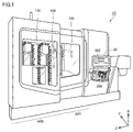
- FIG. 1 is a diagram showing an example of a machine tool 10. As shown in FIG.
- Fig. 1 shows a machine tool 10 as a machining center.
- the machine tool 10 may be a horizontal machining center or a vertical machining center.
- the machine tool 10 as a machining center will be described below, the machine tool 10 is not limited to a machining center.
- the machine tool 10 may be a lathe, an additional processing machine, or other cutting or grinding machine.
- a machine tool 10 is provided with an operation panel 20 .
- the operation panel 20 includes a display 205 for displaying various information regarding machining, and operation keys 206 for receiving various operations for the machine tool 10 .
- the machine tool 10 has a machining area AR1 and a tool area AR2. Each of the machining area AR1 and the tool area AR2 is partitioned by a cover.
- a spindle head 130 is provided in the machining area AR1.
- An ATC 160 and a magazine 170 are provided in the tool area AR2. Magazine 170 is configured to be able to hold a plurality of tools.
- the ATC 160 attaches a designated tool among the tools held in the magazine 170 to the spindle head 130 through the door D provided in the partition between the machining area AR1 and the tool area AR2.
- the door D is a sliding door, and is opened and closed by a drive source such as a motor.
- FIG. 2 is a diagram showing an example of a workpiece after machining and an example of a screen displayed on the operation panel 20. As shown in FIG.
- a damaged workpiece W is obtained through machining by the machine tool 10 .
- the operator needs to identify the cause of the damage. Scratches on the workpiece W are caused, for example, by tool wear and tool breakage. Therefore, the machine tool 10 presents the operator with the tools involved in the machining of the damaged portion P0 in order to assist the operator in investigating the cause.
- step S1 the operator confirms whether or not the post-processing work W has been processed as intended. As a result, the operator finds a damaged portion P0 in the work W. As shown in FIG.
- step S2 the operator displays a confirmation screen 230 on the display 205 of the operation panel 20.
- Confirmation screen 230 includes display areas 233 and 235 .
- the display area 233 displays the three-dimensional model MD of the workpiece.
- the three-dimensional model MD is three-dimensional data representing the shape of the workpiece W after or during machining.
- the data format of the three-dimensional model MD is arbitrary.
- the three-dimensional model MD may be a wireframe model whose three-dimensional shape is defined by a combination of points and lines, or a surface model whose three-dimensional shape is defined by a combination of surfaces.
- it may be a spatial grid model in which information indicating the presence or absence or type of an object is associated with each three-dimensional coordinate value.
- the three-dimensional model MD may be downloaded from an external device, defined by a user, or based on machining information 223 (see FIG. 5) used for machining the workpiece W, which will be described later. may be generated.
- the machining information 223 is information that defines a tool used in machining the workpiece W and a machining path of the tool. Details of the processing information 223 will be described later.
- the operation panel 20 generates a two-dimensional projection image representing the three-dimensional model MD from a specific viewpoint by projection transformation, and displays the projection image in the display area 233 .
- the machine tool 10 changes the display direction (projection direction) of the three-dimensional model MD in conjunction with the user's operation in the display area 233 .
- the user can change the display direction of the three-dimensional model MD by sliding a finger while touching the display area 233 .
- the three-dimensional model MD displayed in the display area 233 is configured to accept designation of locations.
- the "place” here means a part of the surface of the three-dimensional model MD.
- the “location” may be any one of the surfaces forming the three-dimensional model MD, a partial area within the three-dimensional model MD, or a may be one point.
- the worker designates a point P1 on the three-dimensional model MD.
- a point P1 corresponds to a damaged portion P0 of the actual workpiece W.
- the machine tool 10 receives the specification of the point P1 in the three-dimensional model MD, it identifies one or more tools involved in machining the point P1 based on machining information 223 (see FIG. 5), which will be described later. As a result, it is assumed that "tool B" and "tool D" are identified.
- the machine tool 10 displays the tool information of the identified "tool B" and "tool D” in the display area 235.
- the tool information includes at least one of tool type, tool name, tool diameter, tool length, and tool image.
- the tool diameter represents the radius or diameter of the tool in a direction perpendicular to the axial direction of a spindle 132 (see FIG. 3), which will be described later.
- the tool length represents the length of the tool in the axial direction of spindle 132 .
- the tool names "tool B" and "tool D" are displayed in the display area 235 as the tool information.
- the operator can know the information of the tool that processed the damaged portion P0 of the work W.
- the operator can investigate the cause of the damage to the work W by checking the condition of the tool.
- FIG. 3 is a diagram showing a configuration example of a drive mechanism in the machine tool 10. As shown in FIG.
- the machine tool 10 includes a control section 50, a rotation drive section 110A, a position drive section 110B, a magazine drive section 110M (driving device), a spindle head 130, and a camera 140. .
- control unit 50 means a device that controls the machine tool 10.
- the device configuration of the control unit 50 is arbitrary.
- the control section 50 may be composed of a single control unit, or may be composed of a plurality of control units. In the example of FIG. 3 , the control section 50 is composed of the operation panel 20 and the CNC unit 30 .
- the operation panel 20 communicates with the CNC unit 30, for example, via a communication path NW1 (eg, wireless LAN, wired LAN, field network, etc.). Further, operation panel 20 communicates with camera 140 via communication path NW2 (for example, wireless LAN, wired LAN, field network, etc.).
- NW1 eg, wireless LAN, wired LAN, field network, etc.
- NW2 for example, wireless LAN, wired LAN, field network, etc.
- An image processing program is installed in the operation panel 20, and various image processing is performed on the image acquired from the camera 140.
- the CNC unit 30 Upon receiving the machining start command, the CNC unit 30 starts executing a pre-designed machining program.
- the machining program is written in, for example, an NC (Numerical Control) program.
- the CNC unit 30 controls the rotation drive section 110A and the position drive section 110B to drive the spindle head 130 according to the machining program.
- the spindle head 130 includes a spindle tube 131 and a spindle 132 .
- the main shaft 132 is rotatably supported by the main shaft tube 131 .
- a tool 134 selected from a magazine 170 (see FIG. 1) is mounted on the spindle 132 .
- the tool 134 rotates in conjunction with the spindle 132 .
- the rotation drive section 110A is a drive mechanism for changing the angle of the main shaft 132.
- the rotation driving unit 110A rotates in a rotation direction centered on the X-axis direction (A-axis), a rotation direction centered on the Y-axis direction (B-axis), and a rotation center centered on the Z-axis direction. At least one angle of the rotation direction (C axis) is adjusted.
- the device configuration of the rotation drive unit 110A is arbitrary.
- the rotation driving section 110A may be composed of a single driving unit, or may be composed of a plurality of driving units. In the example of FIG. 3, the rotation driving section 110A is composed of servo drivers 111B and 111C.
- the position drive unit 110B is a drive mechanism for changing the position of the main shaft 132.
- position driver 110B adjusts at least one position in the X-axis direction, Y-axis direction, and Z-axis direction.
- the device configuration of the position driving section 110B is arbitrary.
- the position driving section 110B may be composed of a single driving unit, or may be composed of a plurality of driving units. In the example of FIG. 3, the position driving section 110B is composed of servo drivers 111X to 111Z.
- the servo driver 111B sequentially receives input of the target rotational speed from the CNC unit 30 and controls a servomotor (not shown) for rotating the spindle head 130 in the B-axis direction.
- the servo driver 111B calculates the actual rotation speed of the servomotor from a feedback signal of an encoder (not shown) for detecting the rotation angle of the servomotor, and the actual rotation speed is the target rotation speed. If the actual rotation speed is higher than the target rotation speed, the rotation speed of the servo motor is lowered. In this way, the servo driver 111B brings the rotation speed of the servomotor closer to the target rotation speed while sequentially receiving the feedback of the rotation speed of the servomotor. Thereby, the servo driver 111B adjusts the rotational speed of the spindle head 130 in the B-axis direction.
- the servo driver 111C sequentially receives input of the target rotational speed from the CNC unit 30, and controls a servomotor (not shown) for rotationally driving the main shaft 132 in a rotational direction about the axial direction of the main shaft 132. .
- the servo driver 111C calculates the actual rotation speed of the servomotor from a feedback signal of an encoder (not shown) for detecting the rotation angle of the servomotor, and the actual rotation speed is the target rotation speed. If the actual rotation speed is higher than the target rotation speed, the rotation speed of the servo motor is lowered. In this way, the servo driver 111C brings the rotation speed of the servomotor closer to the target rotation speed while sequentially receiving the feedback of the rotation speed of the servomotor. Thereby, the servo driver 111C adjusts the rotation speed of the main shaft 132 in the rotation direction with the axial direction of the main shaft 132 as the rotation center.
- the servo driver 111X sequentially receives input of target positions from the CNC unit 30 and controls a servo motor (not shown).
- the servomotor feeds and drives a moving body to which the spindle head 130 is attached via a ball screw (not shown) to move the spindle head 130 to an arbitrary position in the X-axis direction.
- the method of controlling the servomotor by the servo driver 111X is the same as that of the servo drivers 111B and 111C, so the description thereof will not be repeated.
- the servo driver 111Y sequentially receives input of target positions from the CNC unit 30 and controls a servo motor (not shown).
- the servomotor feeds and drives a moving body to which the spindle head 130 is attached via a ball screw (not shown) to move the spindle 132 to an arbitrary position in the Y-axis direction.
- the method of controlling the servomotor by the servo driver 111Y is the same as that of the servo drivers 111B and 111C, so the description thereof will not be repeated.
- the servo driver 111Z sequentially receives input of target positions from the CNC unit 30 and controls a servo motor (not shown).
- the servomotor feeds and drives a moving body to which the spindle head 130 is attached via a ball screw (not shown) to move the spindle 132 to an arbitrary position in the Z-axis direction.
- the method of controlling the servomotor by the servo driver 111Z is the same as that of the servo drivers 111B and 111C, so the description thereof will not be repeated.
- the rotation driving section 110A may be configured by another motor driver.
- the rotation drive section 110A may be configured with one or more motor drivers for a stepping motor.
- the position driver 110B may consist of one or more motor drivers for stepping motors.
- the magazine drive unit 110M is a drive mechanism for rotationally driving the magazine 170 (see FIG. 1) described above.
- the device configuration of the magazine drive unit 110M is arbitrary.
- the magazine driving section 110M may be composed of a single driving unit, or may be composed of a plurality of driving units.
- magazine driving section 110M includes a servo driver (not shown).
- the servo driver sequentially receives target position inputs from the CNC unit 30 and controls a servo motor (not shown).
- the servo motor rotates the magazine 170 and moves a designated tool among the tools held by the magazine 170 to an arbitrary position.
- the magazine driving section 110M may be configured by another motor driver.
- the magazine driver 110M may be configured with one or more motor drivers for stepping motors.
- the camera 140 is configured to photograph the tool 134 attached to the spindle 132.
- the camera 140 may be a CCD (Charge Coupled Device) camera, an infrared camera (thermography), or any other type of camera.
- FIG. 4 is a diagram showing an example of the functional configuration of the machine tool 10. As shown in FIG.
- the control unit 50 includes, as an example of a functional configuration, an input reception unit 52, a used tool identification unit 54, a tool information identification unit 56, a display control unit 60, and a drive control unit 62.
- the functional configuration will be described in order.
- all of the functional configuration shown in FIG. 4 may be implemented in the operation panel 20 described above, or may be implemented in the CNC unit 30 described above.
- part of the functional configuration shown in FIG. 4 may be implemented in the operation panel 20 described above, and the rest of the functional configuration may be implemented in the CNC unit 30 described above.
- part of the functional configuration shown in FIG. 4 may be implemented in devices other than the operation panel 20 and the CNC unit 30 .
- the input reception unit 52 is a functional module that receives user operation inputs from various input devices in the machine tool 10 .
- the input device includes, for example, the operation panel 20 described above.
- the input accepting unit 52 accepts designation of a portion of the three-dimensional model MD (see FIG. 2) displayed on the display 205 of the operation panel 20 . More specifically, since the touch position on display 205 is indicated by two-dimensional coordinate values, input reception unit 52 transforms the two-dimensional coordinate values into three-dimensional coordinate values according to a predetermined coordinate conversion formula. Convert to three-dimensional coordinate values on the model MD.
- the three-dimensional coordinate values indicate the intersections between the straight lines extending in the three-dimensional space from the touch position on the display 205 in the projection direction of the three-dimensional model MD and the planes forming the three-dimensional model MD.
- the coordinate values of the three-dimensional model MD are output to the used tool identifying section 54 .
- FIG. 5 is a conceptual diagram schematically showing the used tool identification processing by the used tool identification unit 54. As shown in FIG. 5
- the used tool identification unit 54 identifies the used tool that has machined the specified location on the three-dimensional model MD based on the machining information 223 shown in FIG.
- the machining information 223 defines at least a tool used for machining a workpiece and a machining path of the tool.
- the machining information 223 includes the starting point of the machining path, the end point of the machining path, the type of tool used, the type of machining path, and the G code for realizing machining on the machining path. , defined for each processing path.
- the processing information 223 is generated by various methods. As an example, some machine tools 10 have a function of automatically generating a machining program in response to interactive questions from the user. The processing information 223 is generated by the function, for example.
- FIG. 6 is a diagram showing a creation screen 250, which is an example of an interactive machining program creation screen.
- Generation screen 250 is displayed, for example, on display 205 of operation panel 20 .
- the generation screen 250 shows icons 21 to 27 for designating the machining path.
- Each of the icons 21 to 27 is associated with a program code (eg, G code) or the like for realizing the processing indicated by the icon. Machining paths, tools to be used, and the like are defined in the program code.
- G code program code
- Icons 21 to 27 shown in FIG. 6 indicate some of the icons that can be selected by the user.
- the user can generate an arbitrary machining program by selecting various icons according to dialogue.
- the machining information 223 defines information defining the machining path and the tools used on the machining path.
- a three-dimensional model MD of the workpiece obtained by machining based on the machining information 223 may be further generated.
- the data format of the processing information 223 is not limited to the format shown in FIG.
- the machining information 223 may be any information including at least a tool used for machining a workpiece and a machining path of the tool.
- the machining information 223 may be the machining program itself.
- the function of generating the machining program by the interactive automatic generation function was explained, but the machining program may be designed by the operator writing the program code.
- the tool-to-be-used identifying unit 54 identifies machining paths corresponding to specified locations on the three-dimensional model MD as path candidates from among the machining paths defined in the machining information 223 . More specifically, the used tool identification unit 54 calculates the distance between each machining path defined in the machining information 223 and the specified location on the three-dimensional model MD.
- the used tool identification unit 54 identifies machining paths whose calculated distance is equal to or less than a predetermined value as path candidates. In another aspect, the used tool identification unit 54 identifies a predetermined number of machining paths with the shortest calculated distances as path candidates. The predetermined number is an integer of 1 or more.
- the used tool identifying unit 54 refers to the machining information 223 to identify the tool type associated with the identified path candidate.
- the specified tool is regarded as the used tool involved in machining the specified location on the three-dimensional model MD.
- "tool B" is specified as the tool to be used.
- FIG. 7 is a conceptual diagram schematically showing the tool information specifying process by the tool information specifying unit 56. As shown in FIG. 7,
- the tool information specifying unit 56 specifies tool information related to the used tool specified by the used tool specifying unit 54 .
- the tool information specifying unit 56 acquires the tool database 224.
- the tool database 224 may be pre-stored in the machine tool 10, or may be obtained from an external server.
- the tool database 224 defines tool information for each tool.
- the tool information includes a tool number for uniquely identifying a tool, a tool type indicating the type of tool, a tool name, tool size information such as tool diameter and tool length, and a tool image representing the tool. including.
- Each tool image included in the tool database 224 is, for example, an image obtained from the camera 140 described above.
- the camera 140 photographs the tool at various timings, such as before the start of machining of the work or after the end of machining the work.
- the tool information identification unit 56 identifies the tool type corresponding to the used tool identified by the used tool identification unit 54 from among the tool types defined in the tool database 224 . After that, the tool information specifying unit 56 acquires tool information associated with the specified tool type. In the example of FIG. 7, tool information related to "tool B" is acquired.
- the acquired tool information includes, for example, at least one of a tool name, tool size information such as tool diameter and tool length, and a tool image.
- tool size information such as tool diameter and tool length is defined in advance in the tool database 224
- the tool size may be specified by other methods.
- the tool information identifying unit 56 may identify the size of the tool based on the tool image obtained from the camera 140. More specifically, the tool information specifying unit 56 drives the used tool specified by the used tool specifying unit 54 in front of the camera 140 and causes the camera 140 to photograph the used tool. Next, the tool information specifying unit 56 performs predetermined image processing on the tool image obtained from the camera 140 to search for a tool portion within the tool image. Various existing image processing is used for the search processing of the tool portion. The tool information specifying unit 56 specifies size information of the used tool based on the tool portion searched from the tool image.
- the tool information specifying unit 56 may measure the size of the used tool using a distance sensor such as a laser sensor or other measuring device.
- FIG. 8 is a diagram showing a modified example of the confirmation screen 230 shown in FIG. 2 described above.
- the confirmation screen 230 shown in FIG. 8 differs from the confirmation screen 230 shown in FIG. 2 in that it further includes a display area 240 for tool information. Other points are the same as the confirmation screen 230 shown in FIG. 2, so the description of the other points will not be repeated.
- the display control unit 60 not only displays the used tool specified by the used tool specifying unit 54 in the display area 235, but also displays the tool information specified by the tool information specifying unit 56 in the display area 240. That is, the display control unit 60 displays in the display area 240 information about the used tool that has machined the designated portion P1 in the three-dimensional model MD.
- the used tools displayed in the display area 235 are configured to be selectable, and tool information about the selected used tool is displayed in the display area 240 .
- tool information about the selected used tool is displayed in the display area 240 .
- “tool B" is selected, and tool information related to "tool B” is displayed in the display area 240.
- the tool information displayed in the display area 240 includes size information of the used tool.
- the size information includes at least one of the tool diameter of the used tool and the tool length of the used tool. By confirming the size information, the operator can know the size information of the tool involved in the machining of the portion P1.
- the tool information displayed in display area 240 includes a tool image representing the tool in use.
- the operator can confirm the state of the tool involved in the machining of the portion P1 on the image, and can discover wear or damage of the tool.
- the tool image displayed in the display area 240 may be a tool image representing the tool in use in the past or a tool image representing the state of the tool in use at present.
- a tool image representing a past used tool is obtained, for example, from the tool database 224 described above.
- a tool image representing the currently used tool is obtained, for example, by driving the used tool specified in the display area 235 in front of the camera 140 . More specifically, when a specific tool to be used is specified in the display area 235, the machine tool 10 identifies the tool to be used from among the tools stored in the magazine 170 (see FIG. 1). , and the ATC 160 (see FIG. 1) to mount the tool to be used on the spindle 132 . After that, the machine tool 10 drives the spindle 132 so that the used tool is included in the imaging field of the camera 140 and outputs an imaging instruction to the camera 140 . A tool image representing the currently used tool is thereby obtained from the camera 140 .
- the tool in use does not necessarily have to be photographed while attached to the spindle 132 .
- the tool in use may be photographed by camera 140 at a predetermined position within magazine 170 .
- a tool image representing the used tools in magazine 170 is obtained from camera 140 and displayed in display area 240 .
- the tool used does not necessarily have to be photographed in its entirety.
- the camera 140 may photograph a part such as the cutting edge of the used tool.
- a tool image representing a portion of the currently used tool is acquired from camera 140 and displayed in display area 240 .
- FIG. 9 is a diagram showing a confirmation screen 230 according to the modification.
- the display control unit 60 further displays the machining path R of the used tool superimposed on the three-dimensional model MD displayed on the display 205 .
- the user can visually understand the machining path R of the tool that has machined the designated portion of the three-dimensional model MD.
- the display control unit 60 displays the above-described machining information 223 (see FIG. 5) based on the selection of one used tool from among the used tools displayed in the display area 235. By referring to it, the machining path associated with the one used tool is identified. Since the machining path is indicated as a path in the three-dimensional space, the display control unit 60 converts the path into a two-dimensional machining path R by projection conversion with reference to the projection direction of the three-dimensional model MD. . After that, the display control unit 60 displays a two-dimensional machining path R representing a machining path in a three-dimensional space from the projection direction so as to be superimposed on the projection image of the three-dimensional model MD.
- the used tools displayed in the display area 235 are configured to be selectable. Based on the selection of one of the tools in use displayed in the display area 235, the drive control unit 62 predetermines the one tool in use in the magazine 170 (see FIG. 1).
- the magazine driving section 110M (see FIG. 3) is controlled so as to drive to the selected position.
- the predetermined position is a position from which the operator can take out the tool, and is defined in advance in the magazine 170 control program.
- the worker can visually check the condition of the tool used in processing the damaged part of the workpiece, and can discover wear and defects of the tool.
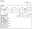
- FIG. 10 is a block diagram showing an example of the hardware configuration of the operation panel 20. As shown in FIG. 10
- the operation panel 20 includes a control circuit 201, a ROM (Read Only Memory) 202, a RAM (Random Access Memory) 203, a communication interface 204, a display 205, operation keys 206, and an auxiliary storage device 220. These components are connected to the internal bus B1.
- ROM Read Only Memory
- RAM Random Access Memory
- the control circuit 201 is composed of, for example, at least one integrated circuit.
- Integrated circuits include, for example, at least one CPU (Central Processing Unit), at least one GPU (Graphics Processing Unit), at least one ASIC (Application Specific Integrated Circuit), at least one FPGA (Field Programmable Gate Array), or It can be configured by a combination of
- the control circuit 201 controls the operation of the operation panel 20 by executing various programs such as the control program 222 .
- the control program 222 is a program for realizing various functional configurations shown in FIG.
- the control circuit 201 reads out the programs from the auxiliary storage device 220 or the ROM 202 to the RAM 203 based on the execution instructions of various programs.
- a RAM 203 functions as a working memory and temporarily stores various data necessary for executing various programs.
- the communication interface 204 is a communication unit for realizing communication using a LAN (Local Area Network) cable, WLAN, Bluetooth (registered trademark), or the like.
- the operation panel 20 realizes communication with an external device such as a CNC unit 30 (see FIG. 3), which will be described later, via the communication interface 204 .
- the display 205 is, for example, a liquid crystal display, organic EL display, or other display device.
- the display 205 sends an image signal for displaying an image to the display 205 according to a command from the control circuit 201 or the like.
- the display 205 is configured by, for example, a touch panel, and receives various operations for the machine tool 10 by touch operations.
- the operation key 206 is composed of a plurality of hardware keys and accepts various user operations on the operation panel 20. A signal corresponding to the pressed key is output to the control circuit 201 .
- the auxiliary storage device 220 is, for example, a storage medium such as a hard disk or flash memory.
- the auxiliary storage device 220 stores the control program 222, the machining information 223 described above, the tool database 224 described above, the three-dimensional model MD described above, and the like. These storage locations are not limited to the auxiliary storage device 220, but may be stored in the storage area of the control circuit 201 (eg, cache memory), ROM 202, RAM 203, external equipment (eg, server), and the like.
- control program 222 may be provided not as a standalone program but as part of an arbitrary program. In this case, various processes according to the present embodiment are implemented in cooperation with arbitrary programs. Even a program that does not include such a part of modules does not deviate from the gist of control program 222 according to the present embodiment. Furthermore, some or all of the functions provided by control program 222 may be implemented by dedicated hardware. Furthermore, the control panel 20 may be configured in a form like a so-called cloud service in which at least one server executes part of the processing of the control program 222 .
- FIG. 11 is a block diagram showing an example of the hardware configuration of the CNC unit 30. As shown in FIG. 11
- the CNC unit 30 includes a control circuit 301 , a ROM 302 , a RAM 303 , communication interfaces 304 and 305 , a fieldbus controller 306 and an auxiliary storage device 320 . These components are connected to the internal bus B3.
- the control circuit 301 is composed of, for example, at least one integrated circuit.
- An integrated circuit may be comprised of, for example, at least one CPU, at least one GPU, at least one ASIC, at least one FPGA, or combinations thereof.
- the control circuit 301 controls the operation of the CNC unit 30 by executing various programs such as a control program 322 and a machining program 323.
- the control circuit 301 reads the control program 322 from the ROM 302 to the RAM 303 based on the acceptance of the instruction to execute the control program 322 .
- the RAM 303 functions as a working memory and temporarily stores various data necessary for executing the control program 322 .
- Communication interfaces 304 and 305 are communication units for realizing communication using LAN, WLAN, Bluetooth, or the like.
- CNC unit 30 exchanges data with an external device (for example, operation panel 20 ) via communication interface 304 . Also, the CNC unit 30 exchanges data with an external device (for example, a server) via the communication interface 305 .
- the fieldbus controller 306 is a communication unit for realizing communication with various units connected to the fieldbus.
- units connected to the field bus include the above-described rotation driving section 110A (see FIG. 3), the above-described position driving section 110B (see FIG. 3), and the above-described magazine driving section 110M (see FIG. 3). mentioned.
- the auxiliary storage device 320 is, for example, a storage medium such as a hard disk or flash memory.
- the auxiliary storage device 320 stores a control program 322, a machining program 323, and the like. These storage locations are not limited to the auxiliary storage device 320, but may be stored in the storage area of the control circuit 301 (eg, cache memory), ROM 302, RAM 303, external equipment (eg, server), and the like.
- FIG. 12 is a flow chart showing the flow of display control of the above confirmation screen 230 (see FIG. 2).
- the processing shown in FIG. 12 is implemented by the control unit 50 of the machine tool 10 executing the control program 222 described above. In other aspects, part or all of the processing may be performed by circuit elements or other hardware.
- step S110 the control unit 50 determines whether or not an operation for calling the confirmation screen 230 described above has been received.
- the user can call the confirmation screen 230 by, for example, touch operation on the display 205 of the operation panel 20 or key input on the operation keys 206 on the operation panel 20 .
- control unit 50 switches control to step S112. Otherwise (NO in step S110), control unit 50 executes the process of step S110 again.
- step S112 the control unit 50 functions as the display control unit 60 (see FIG. 4) and displays the confirmation screen 230 on the display 205 of the operation panel 20.
- the confirmation screen 230 is configured so that the three-dimensional model MD of the workpiece can be read, and displays the projected image of the read three-dimensional model MD in the display area 233 .
- step S120 the control unit 50 functions as the input reception unit 52 (see FIG. 4) and determines whether or not the location of the three-dimensional model MD displayed on the confirmation screen 230 has been specified.
- the user can specify the location of the three-dimensional model MD by, for example, touch operation on the display 205 of the operation panel 20 or key input on the operation keys 206 on the operation panel 20 . If the control unit 50 determines that a location has been specified for the three-dimensional model MD (YES in step S120), the control switches to step S122. Otherwise (NO in step S120), control unit 50 switches control to step S130.
- step S122 the control unit 50 functions as the used tool identification unit 54 (see FIG. 4), refers to the above-described machining information 223 (see FIG. 5), and is involved in the machining of the location specified in step S120. Identify the tools used. Since the method of specifying the used tool is as described above, the description thereof will not be repeated.
- the control unit 50 functions as the tool information specifying unit 56 (see FIG. 4), and acquires tool information regarding the used tool specified at step S122 from the machining information 223 (see FIG. 5). Since the method of specifying the tool information regarding the used tool is as described above, the description thereof will not be repeated.
- the acquired tool information includes, for example, at least one of identification information of the used tool (for example, tool name and tool ID), size information of the used tool (for example, tool diameter and tool length), and tool image. including.
- control unit 50 functions as the display control unit 60 (see FIG. 4) and displays the tool information specified at step S124.
- step S130 the control unit 50 functions as the input receiving unit 52 (see FIG. 4), and determines whether or not one of the used tools displayed in the display area 235 of the confirmation screen 230 has been selected. to decide.
- the user can select the tool to be used by, for example, touch operation on the display 205 of the operation panel 20 or key input on the operation keys 206 of the operation panel 20 .
- control unit 50 determines that one of the tools in use displayed in display area 235 of confirmation screen 230 has been selected (YES in step S130), it switches control to step S132. Otherwise (NO in step S130), control unit 50 switches control to step S140.
- step S132 the control unit 50 functions as the drive control unit 62 (see FIG. 4), and identifies the used tool selected in step S130 from among the tools held in the magazine 170 (see FIG. 1). , controls the magazine driving section 110M (see FIG. 3) so as to drive the used tool to a predetermined position.
- step S140 the control unit 50 determines whether an operation to close the confirmation screen 230 (see FIG. 2) has been received.
- the user can close the confirmation screen 230 by, for example, touch operation on the display 205 of the operation panel 20 or key input on the operation keys 206 on the operation panel 20 .
- control unit 50 determines that an operation to close confirmation screen 230 has been received (YES in step S140)
- the process shown in FIG. 12 ends. Otherwise (NO in step S140), control unit 50 returns to step S120.
Landscapes
- Engineering & Computer Science (AREA)
- Human Computer Interaction (AREA)
- Manufacturing & Machinery (AREA)
- Physics & Mathematics (AREA)
- General Physics & Mathematics (AREA)
- Automation & Control Theory (AREA)
- Mechanical Engineering (AREA)
- Numerical Control (AREA)
Abstract
Description
まず、図1を参照して、工作機械10の外観について説明する。図1は、工作機械10の一例を示す図である。
次に、図2を参照して、操作盤20における表示制御について説明する。図2は、加工後のワークの一例と、操作盤20に表示される画面例とを示す図である。
次に、図3を参照して、工作機械10における各種の駆動機構について説明する。図3は、工作機械10における駆動機構の構成例を示す図である。
次に、図4を参照して、工作機械10の機能構成について説明する。図4は、工作機械10の機能構成の一例を示す図である。
まず、図4に示される入力受付部52の機能について説明する。
次に、図5および図6を参照して、図4に示される使用工具特定部54の機能について説明する。図5は、使用工具特定部54による使用工具の特定処理を概略的に示す概念図である。
次に、図7を参照して、図4に示される工具情報特定部56の機能について説明する。図7は、工具情報特定部56による工具情報の特定処理を概略的に示す概念図である。
次に、図8を参照して、図4に示される表示制御部60の機能について説明する。図8は、上述の図2に示される確認画面230の変形例を示す図である。
次に、上述の図8を参照して、図4に示される駆動制御部62の機能について説明する。
次に、図10を参照して、操作盤20のハードウェア構成について説明する。図10は、操作盤20のハードウェア構成の一例を示すブロック図である。
次に、図11を参照して、CNCユニット30のハードウェア構成について説明する。図11は、CNCユニット30のハードウェア構成の一例を示すブロック図である。
次に、図12を参照して、上述の確認画面230(図2参照)の表示フローについて説明する。図12は、上述の確認画面230(図2参照)の表示制御の流れを示すフローチャートである。
Claims (7)
- 複数の工具を用いてワークを加工することが可能な工作機械であって、
ディスプレイと、
前記工作機械を制御するための制御部とを備え、
前記ワークの加工で用いられる工具と、当該工具の加工経路とを規定した加工情報を取得する処理と、
前記加工情報に基づいて生成された前記ワークの3次元モデルを前記ディスプレイに表示する処理と、
前記ディスプレイに表示されている前記3次元モデルにおいて、加工されたワークの部分に対応する箇所の指定を受け付ける処理と、
前記加工情報に基づいて、前記指定された箇所の加工に関わった使用工具を特定する処理と、
前記使用工具の情報を前記ディスプレイに表示する処理とを実行する、工作機械。 - 前記制御部は、さらに、
工具のサイズ情報が工具別に対応付けられているデータベースを取得する処理と、
前記データベースに規定されているサイズ情報の内から、前記使用工具に対応付けられているサイズ情報を取得する処理とを実行し、
前記表示する処理で前記ディスプレイに表示される前記情報は、前記取得する処理で取得されたサイズ情報を含む、請求項1に記載の工作機械。 - 前記工作機械は、さらに、当該工作機械内に設けられているカメラを備え、
前記制御部は、さらに、前記使用工具を表わす工具画像を前記カメラから取得する処理を実行し、
前記表示する処理で前記ディスプレイに表示される前記情報は、前記工具画像を含む、請求項1または2に記載の工作機械。 - 前記工作機械は、さらに、
複数の工具を保持することが可能なマガジンと、
前記マガジンを駆動するための駆動装置とを備え、
前記制御部は、さらに、
前記ディスプレイに表示されている前記使用工具の内から、一の使用工具の指定を受け付ける処理と、
前記マガジンに格納されている複数の工具の内の前記指定された一の使用工具を予め定められた位置に駆動するように前記駆動装置を制御する処理とを実行する、請求項1~3のいずれか1項に記載の工作機械。 - 前記制御部は、前記3次元モデルに重ねて前記使用工具の加工経路をさらに表示する処理を実行する、請求項1~4のいずれか1項に記載の工作機械。
- 複数の工具を用いてワークを加工することが可能な工作機械の制御方法であって、
前記ワークの加工で用いられる工具と、当該工具の加工経路とを規定した加工情報を取得するステップと、
前記加工情報に基づいて生成された前記ワークの3次元モデルを前記工作機械のディスプレイに表示するステップと、
前記ディスプレイに表示されている前記3次元モデルにおいて、加工されたワークの部分に対応する箇所の指定を受け付けるステップと、
前記加工情報に基づいて、前記指定された箇所の加工に関わった使用工具を特定するステップと、
前記使用工具の情報を前記ディスプレイに表示するステップとを実行する、制御方法。 - 複数の工具を用いてワークを加工することが可能な工作機械の制御プログラムであって、
前記制御プログラムは、前記工作機械に、
前記ワークの加工で用いられる工具と、当該工具の加工経路とを規定した加工情報を取得するステップと、
前記加工情報に基づいて生成された前記ワークの3次元モデルを前記工作機械のディスプレイに表示するステップと、
前記ディスプレイに表示されている前記3次元モデルにおいて、加工されたワークの部分に対応する箇所の指定を受け付けるステップと、
前記加工情報に基づいて、前記指定された箇所の加工に関わった使用工具を特定するステップと、
前記使用工具の情報を前記ディスプレイに表示するステップとを実行させる、制御プログラム。
Priority Applications (3)
| Application Number | Priority Date | Filing Date | Title |
|---|---|---|---|
| US18/277,100 US20240126230A1 (en) | 2021-02-17 | 2021-09-10 | Machine Tool, Machine Tool Control Method, and Machine Tool Control Program |
| EP21926670.7A EP4293449A4 (en) | 2021-02-17 | 2021-09-10 | Machine tool, machine tool control method, and machine tool control program |
| CN202180093910.7A CN116848477A (zh) | 2021-02-17 | 2021-09-10 | 机床、机床的控制方法以及机床的控制程序 |
Applications Claiming Priority (2)
| Application Number | Priority Date | Filing Date | Title |
|---|---|---|---|
| JP2021023434A JP6915182B1 (ja) | 2021-02-17 | 2021-02-17 | 工作機械、工作機械の制御方法、および工作機械の制御プログラム |
| JP2021-023434 | 2021-02-17 |
Publications (1)
| Publication Number | Publication Date |
|---|---|
| WO2022176241A1 true WO2022176241A1 (ja) | 2022-08-25 |
Family
ID=77057528
Family Applications (1)
| Application Number | Title | Priority Date | Filing Date |
|---|---|---|---|
| PCT/JP2021/033293 Ceased WO2022176241A1 (ja) | 2021-02-17 | 2021-09-10 | 工作機械、工作機械の制御方法、および工作機械の制御プログラム |
Country Status (5)
| Country | Link |
|---|---|
| US (1) | US20240126230A1 (ja) |
| EP (1) | EP4293449A4 (ja) |
| JP (1) | JP6915182B1 (ja) |
| CN (1) | CN116848477A (ja) |
| WO (1) | WO2022176241A1 (ja) |
Citations (6)
| Publication number | Priority date | Publication date | Assignee | Title |
|---|---|---|---|---|
| JPH0757461B2 (ja) * | 1986-04-02 | 1995-06-21 | 日立精機株式会社 | Nc加工デ−タの作画チエツク装置 |
| JP2009526296A (ja) * | 2006-02-10 | 2009-07-16 | シーメンス アクチエンゲゼルシヤフト | 工作機械の摩耗状態を算定するためのシステム |
| WO2013118179A1 (ja) | 2012-02-09 | 2013-08-15 | 三菱電機株式会社 | 工具軌跡表示方法および工具軌跡表示装置 |
| JP2019212040A (ja) * | 2018-06-05 | 2019-12-12 | ファナック株式会社 | 位置情報表示システム |
| WO2021014748A1 (ja) * | 2019-07-24 | 2021-01-28 | 株式会社日立製作所 | 製造工程設計方法及び製造工程設計システム |
| WO2021024438A1 (ja) * | 2019-08-07 | 2021-02-11 | ヤマザキマザック株式会社 | 工作機械、工作機械の工具負荷表示方法、及び工作機械のためのプログラム |
Family Cites Families (7)
| Publication number | Priority date | Publication date | Assignee | Title |
|---|---|---|---|---|
| JPS60167738A (ja) * | 1984-02-06 | 1985-08-31 | Fanuc Ltd | 自動工具交換装置の工具表示方式 |
| GB9901887D0 (en) * | 1999-01-29 | 1999-03-17 | Lightwork Design Ltd | Machining simulation method and apparatus |
| JP2016218550A (ja) * | 2015-05-15 | 2016-12-22 | ファナック株式会社 | 加工に使用する工具の取付け状態を確認する数値制御装置 |
| JP6328600B2 (ja) * | 2015-11-20 | 2018-05-23 | ファナック株式会社 | 推奨保守通知システム |
| US20190080446A1 (en) * | 2017-09-11 | 2019-03-14 | All Axis Robotics, LLC | System and method for automated defect detection |
| JP6456452B1 (ja) * | 2017-09-29 | 2019-01-23 | 株式会社牧野フライス製作所 | 工作機械の制御装置 |
| DE102017128628A1 (de) * | 2017-12-01 | 2019-06-06 | Point 8 Gmbh | Verfahren zum Erfassen mindestens eines Werkzeugzustands eines Werkzeugs einer Werkzeugmaschine zur Bearbeitung von Werkstücken sowie Werkzeugmaschine |
-
2021
- 2021-02-17 JP JP2021023434A patent/JP6915182B1/ja active Active
- 2021-09-10 WO PCT/JP2021/033293 patent/WO2022176241A1/ja not_active Ceased
- 2021-09-10 CN CN202180093910.7A patent/CN116848477A/zh active Pending
- 2021-09-10 EP EP21926670.7A patent/EP4293449A4/en active Pending
- 2021-09-10 US US18/277,100 patent/US20240126230A1/en active Pending
Patent Citations (6)
| Publication number | Priority date | Publication date | Assignee | Title |
|---|---|---|---|---|
| JPH0757461B2 (ja) * | 1986-04-02 | 1995-06-21 | 日立精機株式会社 | Nc加工デ−タの作画チエツク装置 |
| JP2009526296A (ja) * | 2006-02-10 | 2009-07-16 | シーメンス アクチエンゲゼルシヤフト | 工作機械の摩耗状態を算定するためのシステム |
| WO2013118179A1 (ja) | 2012-02-09 | 2013-08-15 | 三菱電機株式会社 | 工具軌跡表示方法および工具軌跡表示装置 |
| JP2019212040A (ja) * | 2018-06-05 | 2019-12-12 | ファナック株式会社 | 位置情報表示システム |
| WO2021014748A1 (ja) * | 2019-07-24 | 2021-01-28 | 株式会社日立製作所 | 製造工程設計方法及び製造工程設計システム |
| WO2021024438A1 (ja) * | 2019-08-07 | 2021-02-11 | ヤマザキマザック株式会社 | 工作機械、工作機械の工具負荷表示方法、及び工作機械のためのプログラム |
Also Published As
| Publication number | Publication date |
|---|---|
| CN116848477A (zh) | 2023-10-03 |
| EP4293449A4 (en) | 2024-12-25 |
| US20240126230A1 (en) | 2024-04-18 |
| JP2022125697A (ja) | 2022-08-29 |
| JP6915182B1 (ja) | 2021-08-04 |
| EP4293449A1 (en) | 2023-12-20 |
Similar Documents
| Publication | Publication Date | Title |
|---|---|---|
| JP6457468B2 (ja) | バリ取り装置 | |
| JP6677706B2 (ja) | リンク情報生成装置、リンク情報生成方法及びリンク情報生成プログラム | |
| JP2006004128A (ja) | 干渉確認装置 | |
| JP7120894B2 (ja) | 3次元モデル作成装置、加工シミュレーション装置、工具経路自動生成装置 | |
| JP2005106825A (ja) | 受像装置の位置および方向づけの決定方法および装置 | |
| JP2002172543A (ja) | 加工装置の制御パラメータ設定装置及び制御パラメータ設定方法 | |
| CN104768706A (zh) | 加工程序生成方法及装置 | |
| JP7708904B2 (ja) | 安全パラメータを設定する装置、教示装置、及び方法 | |
| JP2005128686A (ja) | 数値制御装置 | |
| KR101468751B1 (ko) | 그래픽 기반의 사용자 인터페이스를 갖는 수치제어시스템 | |
| JP2006227886A (ja) | サーボ制御装置及びサーボ系の調整方法 | |
| JP2762788B2 (ja) | 移動体の動作表示装置及びその表示方法 | |
| JP7135225B1 (ja) | 工作機械、制御方法、および制御プログラム | |
| JP2017091429A (ja) | Ncプログラム作成装置 | |
| JP6915182B1 (ja) | 工作機械、工作機械の制御方法、および工作機械の制御プログラム | |
| TWI845727B (zh) | 工具資訊設定裝置及工作機械 | |
| WO2022176840A1 (ja) | 工作機械、表示方法、および表示プログラム | |
| JP7038939B1 (ja) | 工作機械、工作機械の制御方法、および工作機械の制御プログラム | |
| TWI684841B (zh) | 加工傾斜平面的多軸工具機的程式碼產生方法及其裝置 | |
| JP6935606B1 (ja) | 情報処理装置および情報処理プログラム | |
| JP2675200B2 (ja) | ロボット | |
| JP6219030B2 (ja) | 加工用データ生成装置、及び工作機械 | |
| JP6887070B1 (ja) | 工作機械、表示制御方法、および表示制御プログラム | |
| JP6900561B1 (ja) | 工作機械、情報処理方法、および情報処理プログラム | |
| WO2018096675A1 (ja) | 加工プログラム変換装置及び数値制御装置 |
Legal Events
| Date | Code | Title | Description |
|---|---|---|---|
| 121 | Ep: the epo has been informed by wipo that ep was designated in this application |
Ref document number: 21926670 Country of ref document: EP Kind code of ref document: A1 |
|
| WWE | Wipo information: entry into national phase |
Ref document number: 202180093910.7 Country of ref document: CN |
|
| WWE | Wipo information: entry into national phase |
Ref document number: 2021926670 Country of ref document: EP |
|
| NENP | Non-entry into the national phase |
Ref country code: DE |
|
| ENP | Entry into the national phase |
Ref document number: 2021926670 Country of ref document: EP Effective date: 20230915 |
|
| WWE | Wipo information: entry into national phase |
Ref document number: 18277100 Country of ref document: US |