WO2022176331A1 - Système de prédiction de la durée de vie d'un engin de chantier - Google Patents
Système de prédiction de la durée de vie d'un engin de chantier Download PDFInfo
- Publication number
- WO2022176331A1 WO2022176331A1 PCT/JP2021/045028 JP2021045028W WO2022176331A1 WO 2022176331 A1 WO2022176331 A1 WO 2022176331A1 JP 2021045028 W JP2021045028 W JP 2021045028W WO 2022176331 A1 WO2022176331 A1 WO 2022176331A1
- Authority
- WO
- WIPO (PCT)
- Prior art keywords
- life
- strain
- calculation unit
- life prediction
- work machine
- Prior art date
- Legal status (The legal status is an assumption and is not a legal conclusion. Google has not performed a legal analysis and makes no representation as to the accuracy of the status listed.)
- Ceased
Links
Images


Classifications
-
- E—FIXED CONSTRUCTIONS
- E02—HYDRAULIC ENGINEERING; FOUNDATIONS; SOIL SHIFTING
- E02F—DREDGING; SOIL-SHIFTING
- E02F9/00—Component parts of dredgers or soil-shifting machines, not restricted to one of the kinds covered by groups E02F3/00 - E02F7/00
- E02F9/20—Drives; Control devices
- E02F9/22—Hydraulic or pneumatic drives
- E02F9/2278—Hydraulic circuits
- E02F9/2292—Systems with two or more pumps
-
- G—PHYSICS
- G01—MEASURING; TESTING
- G01M—TESTING STATIC OR DYNAMIC BALANCE OF MACHINES OR STRUCTURES; TESTING OF STRUCTURES OR APPARATUS, NOT OTHERWISE PROVIDED FOR
- G01M5/00—Investigating the elasticity of structures, e.g. deflection of bridges or air-craft wings
- G01M5/0041—Investigating the elasticity of structures, e.g. deflection of bridges or air-craft wings by determining deflection or stress
-
- E—FIXED CONSTRUCTIONS
- E02—HYDRAULIC ENGINEERING; FOUNDATIONS; SOIL SHIFTING
- E02F—DREDGING; SOIL-SHIFTING
- E02F9/00—Component parts of dredgers or soil-shifting machines, not restricted to one of the kinds covered by groups E02F3/00 - E02F7/00
- E02F9/20—Drives; Control devices
- E02F9/2025—Particular purposes of control systems not otherwise provided for
- E02F9/2054—Fleet management
-
- E—FIXED CONSTRUCTIONS
- E02—HYDRAULIC ENGINEERING; FOUNDATIONS; SOIL SHIFTING
- E02F—DREDGING; SOIL-SHIFTING
- E02F9/00—Component parts of dredgers or soil-shifting machines, not restricted to one of the kinds covered by groups E02F3/00 - E02F7/00
- E02F9/26—Indicating devices
- E02F9/267—Diagnosing or detecting failure of vehicles
-
- G—PHYSICS
- G01—MEASURING; TESTING
- G01M—TESTING STATIC OR DYNAMIC BALANCE OF MACHINES OR STRUCTURES; TESTING OF STRUCTURES OR APPARATUS, NOT OTHERWISE PROVIDED FOR
- G01M99/00—Subject matter not provided for in other groups of this subclass
-
- G—PHYSICS
- G05—CONTROLLING; REGULATING
- G05B—CONTROL OR REGULATING SYSTEMS IN GENERAL; FUNCTIONAL ELEMENTS OF SUCH SYSTEMS; MONITORING OR TESTING ARRANGEMENTS FOR SUCH SYSTEMS OR ELEMENTS
- G05B23/00—Testing or monitoring of control systems or parts thereof
- G05B23/02—Electric testing or monitoring
- G05B23/0205—Electric testing or monitoring by means of a monitoring system capable of detecting and responding to faults
- G05B23/0259—Electric testing or monitoring by means of a monitoring system capable of detecting and responding to faults characterized by the response to fault detection
- G05B23/0283—Predictive maintenance, e.g. involving the monitoring of a system and, based on the monitoring results, taking decisions on the maintenance schedule of the monitored system; Estimating remaining useful life [RUL]
Definitions
- the present invention relates to a work machine life prediction system.
- the work machine operation status capture system disclosed in Patent Document 1 includes transmission means for sending an e-mail to a server about the work status of each part of the work machine, and a computer that can access the server.
- a status acquisition unit that accesses and acquires the operating conditions saved in the server, a display unit that displays the operating conditions acquired by the situation acquiring unit, and automatic failure of the work machine based on the acquired operating conditions.
- a failure estimating unit for estimating systematically.
- a working machine life prediction system includes a working body provided in a machine body, a hydraulic actuator that operates the working body, and operation information when at least one of the working body and the hydraulic actuator operates.
- a work machine life prediction system comprising an operation detection device that detects and a life calculation unit for calculating the life of the life prediction target part from the strain calculated by the strain calculation unit.
- the operation detection device detects, as the operation information, a hydraulic cylinder pressure of a hydraulic cylinder provided as the hydraulic actuator and posture information of the working object
- the strain calculation unit detects the hydraulic cylinder pressure and the The strain is calculated based on the posture information.
- the operation detection device detects, as the posture information, a rotation angle of a member included in the working body with respect to another member, or a stroke of the hydraulic cylinder.
- a work machine life prediction system includes a communication device that is provided in the work machine and that transmits the operation information, the strain calculation unit, and the life calculation unit. and a management device that predicts the life of the life prediction target part included in the work machine based on the above.
- the work machine includes the strain calculation unit and a communication device that transmits information regarding the strain calculated by the strain calculation unit, includes the life calculation unit, and includes the information regarding the strain transmitted from the communication device.
- the present invention it is possible to easily predict the service life of the service life prediction target part from the operation information when at least one of the working body and the hydraulic actuator operates.
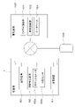
- FIG. 1 shows an overall view of a work machine life prediction system
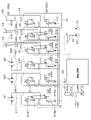
- FIG. 1 is a schematic diagram of a hydraulic system (hydraulic circuit) of a working machine
- FIG. It is a figure which shows operation
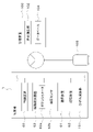
- FIG. 11 shows an overall view of a working machine life prediction system in a first modified example.
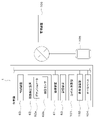
- FIG. 11 shows an overall view of a working machine life prediction system in a second modified example.
- FIG. 11 shows an overall diagram of a work machine life prediction system in a third modified example. It is a figure which shows the side view of a backhoe.
- FIG. 1 shows an overall view of a work machine life prediction system.
- the work machine life prediction system is a system that collects operation information from a plurality of work machines 1 and performs life prediction of a part of each work machine 1 whose life is to be predicted.
- the working machine 1 will be described.
- FIG. 7 shows a backhoe, which is a turning work machine, as the work machine 1 .
- the working machine 1 is not limited to a backhoe, and may be a construction machine such as a loader, a tractor, a combine harvester, an agricultural machine such as a rice transplanter.
- the working machine 1 includes a machine body (swivel base) 2 , a traveling device 3 , and a working device 4 .
- a cabin 5 is mounted on the airframe 2 .
- a driver's seat 6 is provided inside the cabin 5 .
- the direction in which the driver (operator) seated in the driver's seat 6 of the work machine 1 faces (the direction of arrow A1 in FIG. 7) is referred to as the front, and the opposite direction (the direction of arrow A2 in FIG. 7) is referred to as the rear. It says.
- the left side of the driver (the front side in FIG. 7) is called the left side
- the right side of the driver (the far side in FIG. 7) is called the right side.
- the horizontal direction which is the direction perpendicular to the longitudinal direction K1
- the body width direction is called the body width direction.
- the direction from the widthwise central portion of the body 2 to the right or left is referred to as the body outer side.
- the outer side of the fuselage is the width direction of the fuselage and the direction away from the center of the fuselage 2 in the width direction.
- the direction opposite to the outer side of the fuselage is called the inner side of the fuselage.
- the inward direction of the machine body is the width direction of the machine body and the direction toward the center of the machine body 2 in the width direction.
- the traveling device 3 has a traveling body 3L provided on the left side and a traveling body 3R provided on the right side.
- the traveling body 3L and the traveling body 3R are crawler-type traveling devices having a drive wheel 11a, a driven wheel 11b, a plurality of rollers 11e, a frame 11c, and a belt 11d.
- the frame 11c rotatably supports the driving wheel 11a, the driven wheel 11b, and the roller 11e.
- the belt 11d is stretched over the driving wheel 11a, the driven wheel 11b, and the roller 11e.
- a frame 11c of the traveling body 3L supports the first traveling motor ML.
- the power of the first traveling motor ML is transmitted to the driving wheels 11a of the traveling body 3L.
- the frame 11c of the traveling body 3R supports the second traveling motor MR.
- the power of the second traveling motor MR is transmitted to the driving wheels 11a of the traveling body 3R.
- a dozer device 7 is attached to the front portion of the traveling device 3 .
- the dozer device 7 can be raised and lowered (raise and lower the blade) by extending and contracting the dozer cylinder. Note that the work machine 1 may be configured without the dozer device 7 .
- the fuselage 2 is supported on the travel device 3 via a slewing bearing 8 so as to be rotatable about a vertical axis (an axis extending in the vertical direction).
- the machine body 2 is driven to turn by a turning motor MT that is a hydraulic motor (hydraulic actuator).
- the fuselage 2 has a turning base plate 9 that turns around a vertical axis and a weight 10 .
- the swivel base plate 9 is made of a steel plate or the like, and is connected to the swivel bearing 8 .
- a weight 10 is provided at the rear portion of the airframe 2 .
- a prime mover E1 is mounted on the rear portion of the airframe 2. - ⁇ Prime mover E1 is a diesel engine.
- the prime mover E1 may be an electric motor or a hybrid type having a diesel engine and an electric motor.
- the fuselage 2 has a support bracket 13 at the front portion slightly rightward of the center in the width direction of the fuselage.
- a swing bracket 14 is attached to the support bracket 13 so as to be swingable about the vertical axis.
- a working device 4 is attached to the swing bracket 14 .
- the working device 4 has a working body such as a boom 15, an arm 16, a bucket (working tool) 17, and the like.
- the base of the boom 15 is pivotally attached to the swing bracket 14 so as to be rotatable about a horizontal axis (an axis extending in the width direction of the machine body). Therefore, the boom 15 can swing up and down.
- the arm 16 is pivotally attached to the tip side of the boom 15 so as to be rotatable about the horizontal axis.
- the arm 16 can swing back and forth or up and down.
- the bucket 17 is provided on the tip side of the arm 16 so as to be able to scoop and dump.
- the work machine 1 can be equipped with other work implements (preliminary attachments) that can be driven by hydraulic actuators.
- Other working tools include hydraulic breakers, hydraulic crushers, angle blooms, earth augers, pallet forks, sweepers, mowers, snow blowers, and the like.
- the swing bracket 14 is swingable by extension and contraction of the swing cylinder C2 provided inside the body 2.
- the boom 15 is swingable by extension and contraction of the boom cylinder C3.
- the arm 16 is swingable by extension and contraction of the arm cylinder C4.
- the bucket 17 can be swept and dumped by expanding and contracting a bucket cylinder (working tool cylinder) C5.
- the dozer cylinder, swing cylinder C2, boom cylinder C3, arm cylinder C4, and bucket cylinder C5 are configured by hydraulic cylinders (hydraulic actuators).
- the working device 4 may be provided on the machine body 2 and may have other than the boom 15 , the arm 16 and the bucket (working tool) 17 .
- Boom cylinder C3, arm cylinder C4, bucket cylinder C5, etc. are hydraulic actuators that drive the working body.
- FIG. 2 schematically shows a hydraulic circuit (hydraulic system) that operates the hydraulic actuators of the work machine 1 .
- the hydraulic system of the work machine 1 includes work system hydraulic actuators such as a boom cylinder C3, an arm cylinder C4, a bucket cylinder C5, and a swing motor MT, a first travel motor ML, and a second travel motor. It is a system that operates a travel system hydraulic actuator such as MR.
- the hydraulic system in FIG. 2 omits a circuit for controlling the dozer cylinder and the swing cylinder C2.
- a hydraulic pressure sensor 62b is provided to detect .
- the hydraulic system of the working machine 1 has a first hydraulic pump P1, a second hydraulic pump P2, and a plurality of control valves 33.
- the first hydraulic pump P1 is a pump that supplies hydraulic fluid to the work system hydraulic actuator and the travel system hydraulic actuator.
- the first hydraulic pump P1 is, for example, a constant displacement pump or a variable displacement pump.
- the second hydraulic pump P2 is a pump that supplies hydraulic oil for signaling or control, that is, pilot oil.
- the plurality of control valves 33 are valves that control the work system hydraulic actuator and the travel system hydraulic actuator.
- a first hydraulic pump P ⁇ b>1 is connected to the plurality of control valves 33 via oil passages 34 .
- the number of hydraulic pumps provided in the work machine 1 is not particularly limited, and for example, a plurality of pumps that supply hydraulic fluid to the work system hydraulic actuator and the traveling system hydraulic actuator may be provided.
- the plurality of control valves 33 includes a boom control valve 33C that controls the boom cylinder C3, an arm control valve 33D that controls the arm cylinder C4, a bucket control valve 33E that controls the bucket cylinder C5, and a swing control valve 33F that controls the swing motor MT. , a first travel control valve 33G that controls the first travel motor ML, and a second travel control valve 33H that controls the second travel motor MR.
- the boom control valve 33C is connected to the boom cylinder C3 via an oil passage 43.
- the arm control valve 33D is connected through an oil passage 44 to the arm cylinder C4.
- the bucket control valve 33E is connected through an oil passage 45 to the bucket cylinder C5.
- the swing control valve 33F is connected to the swing motor MT via an oil passage 46 .
- the first travel control valve 33G is connected to the first travel motor ML via an oil passage (first oil passage) 47 .
- the second travel control valve 33H is connected to the second travel motor MR via an oil passage (second oil passage) 48 .
- a boom electromagnetic valve 37C is connected to the pressure receiving portion of the boom control valve 33C.
- An arm electromagnetic valve 37D is connected to the pressure receiving portion of the arm control valve 33D.
- a bucket electromagnetic valve 37E is connected to the pressure receiving portion of the bucket control valve 33E.
- a swing solenoid valve 37F is connected to a pressure receiving portion of the swing control valve 33F.
- a forward travel solenoid valve 37G1 and a reverse travel solenoid valve 37G2 are connected to the pressure receiving portion of the first travel control valve 33G.
- a forward solenoid valve 37H1 and a reverse solenoid valve 37H2 are connected to the pressure receiving portion of the second travel control valve 33H.
- electromagnetic valves (37C, 37D, 37E, 37F, 37G1, 37G2, 37H1, or 37H2) are connected to the plurality of control valves 33 corresponding to the respective control valves 33.
- a second hydraulic pump P2 is connected to each solenoid valve via an oil passage (pilot oil passage) 49, and acts on the pressure receiving portion of the control valve 33 corresponding to the solenoid valve 37 according to the opening degree of the solenoid valve. pilot pressure changes.
- the configuration for controlling the operation of the control valve by electronically controlling the opening of the solenoid valve provided in the pilot oil passage will be described, but the hydraulic control method is not limited to this.
- the pilot pressure acting on the control valve may be controlled by operating a remote control valve (pilot operation valve) provided in the pilot oil passage with an operation member. may be directly electronically controlled.
- the boom control valve 33C, arm control valve 33D, bucket control valve 33E, swing control valve 33F, first travel control valve 33G, and second travel control valve 33H are, for example, direct acting spool switching valves.
- Each of the plurality of control valves 33 (33C, 33D, 33E, 33F, 33G, 33H) is supplied to the control valve 33 by pilot oil acting on the pressure receiving portion via the solenoid valve corresponding to the control valve 33. Switch the direction of the hydraulic oil, etc.
- each of the plurality of control valves 33 is operated by a work system hydraulic actuator (boom cylinder C3, arm cylinder C4, bucket cylinder C5, turning motor MT) or a travel system hydraulic actuator (first travel motor ML, second travel motor ML, second travel motor ML). It controls the flow rate of hydraulic oil supplied to the motor MR).
- a work system hydraulic actuator boom cylinder C3, arm cylinder C4, bucket cylinder C5, turning motor MT
- a travel system hydraulic actuator first travel motor ML, second travel motor ML, second travel motor ML. It controls the flow rate of hydraulic oil supplied to the motor MR).
- the work system hydraulic actuators are operated by the control device 19 (control device 19L, control device 19R).
- the operating device 19L has an operation member 40L and a first operation detection section 41L.
- the operating member 40L is a lever that can swing forward, backward, rightward, and leftward from a neutral position.
- the first operation detection section 41L detects the swing amount of the operation member 40L.
- the first operation detection unit 41L is a potentiometer that detects the swing amount (operation amount) from the front, rear, right, and left neutral positions of the operation member 40L.
- the first operation detection unit 41L detects the operation amount and the operation direction of the operation member 40L.
- the first operation detection unit 41L inputs the detected operation amount and operation direction of the operation member 40L to the control device 60 .
- the control device 60 excites the solenoid of the swing electromagnetic valve 37F connected to the pressure receiving portion of the swing control valve 33F in accordance with the amount and direction of operation of the operating member 40L. Thereby, the control device 60 controls the opening degree of the turning electromagnetic valve 37F.
- the pilot pressure acts on the pressure receiving portion of the swing control valve 33F, the position of the swing control valve 33F is switched, and the rotation direction of the swing motor MT is switched according to the position.
- control device 60 excites the solenoid of the arm electromagnetic valve 37D connected to the pressure receiving portion of the arm control valve 33D according to the operation amount and the operation direction of the operation member 40L. Thereby, the control device 60 controls the opening degree of the arm electromagnetic valve 37D. As a result, the pilot pressure acts on the pressure receiving portion of the arm control valve 33D, the position of the arm control valve 33D is switched, and the arm cylinder C4 expands and contracts according to the position.
- the control device 19R has an operation member 40R and a second operation detection section 41R.
- the operation member 40R is a lever that can swing forward, backward, rightward, and leftward from a neutral position.
- the second operation detection section 41R detects the swing amount of the operation member 40R.
- the second operation detection unit 41R is a potentiometer that detects the swing amount (operation amount) from the front, rear, right, and left neutral positions of the operation member 40R.
- the second operation detection unit 41R detects the operation amount and the operation direction of the operation member 40R.
- the second operation detection unit 41R inputs the detected operation amount and operation direction of the operation member 40R to the control device 60 .
- the control device 60 excites the solenoid of the boom electromagnetic valve 37C connected to the pressure receiving portion of the boom control valve 33C according to the operation amount and the operation direction of the operation member 40R. Thereby, the control device 60 controls the opening degree of the boom electromagnetic valve 37C.
- the pilot pressure acts on the pressure receiving portion of the boom control valve 33C, the position of the boom control valve 33C is switched, and the boom cylinder C3 expands and contracts according to the position.
- control device 60 excites the solenoid of the bucket electromagnetic valve 37E connected to the pressure receiving portion of the bucket control valve 33E according to the operation amount and the operation direction of the operation member 40R. Thereby, the control device 60 controls the opening degree of the bucket solenoid valve 37E. As a result, the pilot pressure acts on the pressure receiving portion of the bucket control valve 33E, the position of the bucket control valve 33E is switched, and the bucket cylinder C5 expands and contracts according to the position.
- the operator or the like can operate the machine body 2, the boom 15, the arm 16, and the bucket (work implement) 17 by operating the control device 19L and the control device 19R.
- the working machine 1 includes a control device 60 , a communication device 61 and an operation detection device 62 .
- the control device 60 performs hydraulic control of the electromagnetic valves and the like as described above.
- the control device 60 includes a CPU (Central Processing Unit) that executes program instructions, a ROM (read only memory) that stores computer programs, a RAM (random access memory) that develops various control programs, various control programs and various It is composed of a storage unit (recording medium) such as a memory for storing data.
- a storage unit recording medium
- the communication device 61 is a communication device (communication module) that performs either direct communication or indirect communication with an external device. ), BLE (Bluetooth (registered trademark) Low Energy), LPWA (Low Power, Wide Area), LPWAN (Low-Power Wide-Area Network), and the like. Also, the communication device 61 may be a communication device (communication module) that performs wireless communication via a mobile phone communication network, a data communication network, or the like.
- the operation detection device 62 is an angle sensor that detects the rotation angle of a member included in the working body with respect to other members, or a device that detects the stroke of the hydraulic cylinder as operation information when the work machine 1 operates.
- the operation detection device 62 is a potentiometer 62a, an oil pressure sensor 62b, and the like.
- the potentiometer 62a is, for example, a rotary shaft (first rotary shaft) between the boom 15 and the arm 16, a rotary shaft (second rotary shaft) between the boom 15 and the machine body 2, and a bucket (work implement) 17 ( third rotating shaft) and the like.
- the potentiometer 62a detects the rotation of the first rotation shaft, the second rotation shaft, and the third rotation shaft, thereby detecting the angle between the boom 15 and the arm 16 (first angle ⁇ 1), the boom 15 to the body 2 (second angle ⁇ 2), the angle of the bucket 17 to the arm 16 (third angle ⁇ 3), and the like. That is, the operation detection device 62 can detect the posture of the working object from the first angle ⁇ 1, the second angle ⁇ 2, and the third angle ⁇ 3 obtained by the potentiometer 62a.
- the method of detecting the posture (operation information) of the working object by the operation detection device 62 is not limited to the method using the potentiometer 62a.
- the operation detection device 62 may include a stroke sensor (not shown) that detects the stroke of each hydraulic cylinder (eg boom cylinder C3, arm cylinder C4, bucket cylinder C5) instead of the potentiometer 62a.
- the operation detection device 62 identifies the first angle ⁇ 1, the second angle ⁇ 2, and the third angle ⁇ 3 based on the detection results of those stroke sensors, and detects the posture of the working object.
- the hydraulic pressure sensor 62b is provided in the vicinity of the port through which hydraulic oil is introduced/discharged in each of the boom cylinder C3, the arm cylinder C4, and the bucket cylinder C5.
- the respective pressures (hydraulic cylinder pressures) of C4 and bucket cylinder C5 can be detected. That is, the operation detection device 62 detects the posture of the working object, the hydraulic cylinder pressure, etc. as operation information.
- the operation detection device 62 outputs the detected operation information to the communication device 61 .
- the communication device 61 transmits the operation information output from the operation detection device 62 to the outside.
- the work machine life prediction system includes a management device 100 . Based on operation information collected from a plurality of work machines 1 and the like, the life of a predetermined portion of the work machine is predicted.
- the management device 100 can communicate with the communication device 61 and includes a strain calculator 101 and a life calculator 102 .
- the strain calculation unit 101 and the life calculation unit 102 are composed of electric/electronic circuits provided in the management device 100, programs stored in the management device 100, and the like.
- the strain calculation unit 101 calculates the strain generated in the life prediction target portion of the working machine 1 based on the operation information detected by the operation detection device 62 . For example, the strain calculator 101 calculates the strain based on the hydraulic cylinder pressure and posture information when the hydraulic actuator operates.
- the strain calculator 101 calculates the structural data of the work machine 1, the hydraulic cylinder pressures of the hydraulic cylinders (boom cylinder C3, arm cylinder C4, bucket cylinder C5, etc.) that drive the work body, and the work body Analysis that calculates the load (reaction force) acting on the hydraulic actuators such as the boom cylinder C3, the arm cylinder C4, and the bucket cylinder C5 from the posture information (first angle ⁇ 1, second angle ⁇ 2, third angle ⁇ 3, etc.) have a model. For this reason, the strain calculation unit 101 calculates the load (reaction force) acting on the hydraulic actuator obtained from the analysis model, and the predetermined parts (life prediction target parts) of the boom 15, the arm 16, and the bucket (work tool) 17. Calculate strain.
- the strain calculation unit 101 performs structural analysis based on data on the structure prepared in advance, the hydraulic cylinder pressure of the hydraulic cylinder that drives the working body, and the attitude information of the working body. As a result, the strain calculator 101 calculates the stress, that is, the generated strain (strain) of the boom 15, the arm 16, and the bucket (work implement) 17 at predetermined portions (parts for life prediction) from the structural analysis.
- the database 104 stores hydraulic cylinder pressures of hydraulic cylinders (boom cylinder C3, arm cylinder C4, bucket cylinder C5, etc.) that drive the work object, and posture information of the work object (first angle ⁇ 1, second angle ⁇ 2, second angle ⁇ 2, 3 angles ⁇ 3, etc.) and the generated strain (strain) of the predetermined parts (parts for life prediction) of the boom 15, the arm 16, and the bucket (work tool) 17 are stored in advance (three-dimensional matrix data).
- the strain calculator 101 may calculate the strain of the life prediction target portion by referring to the data.
- the life calculation unit 102 compares the generated strain (strain) of the predetermined portion calculated by the strain calculation unit 101 with the strength of the predetermined portion obtained from the structural data of the boom 15, the arm 16 and the bucket (working tool) 17. By doing so, the life is calculated. For example, the life calculation unit 102 obtains the distribution of generated strain (strain), and compares the frequency of occurrence (number of times of occurrence) of generated strain greater than or equal to a predetermined value from the distribution with the strength of the predetermined portion, thereby determining the life of the predetermined portion. Decide if it's short or long.
- the strain calculator 101 and/or the life calculator 102 may perform the above calculations using machine learning, for example, artificial intelligence such as deep learning.
- the strain calculation unit 101 and/or the life calculation unit 102 have a learned model obtained by deep learning, and the strain (strain) generated in the learned model, the boom 15, the arm 16 and the bucket (work By applying the strength of the predetermined portion obtained from the data of the structure in 17), the life is calculated and whether the life of the predetermined portion is long or short is determined.
- the strain calculator 101 and/or the life calculator 102 may have a trained model obtained using a neural network using an algorithm other than deep learning, such as a recurrent neural network.
- the trained model generates predetermined parts (parts for life prediction) of the boom 15, the arm 16 and the bucket (work tool) 17 based on the structural data, the hydraulic cylinder pressure of the hydraulic cylinder, and the attitude information of the working object. It is a model for calculating strain (strain), or a model for calculating or obtaining life based on generated strain (strain) and structural data.
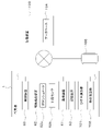
- Fig. 3 shows the operation flow of the work equipment life prediction system.
- the communication device 61 transmits operation information (workpiece posture, hydraulic cylinder pressure) detected by the operation detection device 62 , identification information for identifying the work machine 1 , to the management device 100 (S1).
- the management device 100 receives the operation information and the identification information from the communication device 61 (S1), the management device 100 stores the operation information in the database 104 for each working machine 1, that is, for each identification information (S2).
- the strain calculation unit 101 calculates the strain (generated strain) based on the operation information (hydraulic cylinder pressure and posture information) accumulated in the database 104 ( S3).
- the management device 100 causes the database 104 to store the generated strain as performance information for each working machine 1 (S4).
- the life calculation unit 102 refers to the database 104, calculates the number of times the generated strain has exceeded a predetermined value from the performance information, and Life expectancy is predicted (S5).
- the management device 100 pre-stores in the database 104 data indicating the relationship between the number of times the generated strain exceeds a predetermined value and the service life for each part of the working body, and the service life calculation unit 102 stores the data.
- the life of the target part for life prediction is predicted. It should be noted that the calculated life becomes shorter as the number of times the generated strain exceeds a predetermined value increases.
- the predetermined value may be set for each part of the working body.
- the life prediction method described above is an example and is not limited.
- the management device 100 When the life calculation unit 102 predicts the life (S5), the management device 100 notifies the life prediction result (S6). When there is a portion whose predicted life span is shorter than the predetermined period, the management device 100 notifies the predicted life span of a portion, instead of notifying the mobile terminal 105 or the like of the predetermined life span, of the portion whose life span is shorter than the predetermined period. You may make it notify that it became below.
- the management device 100 includes the strain calculator 101 in the above-described embodiment, the work implement 1 may include the strain calculator 101 and the storage device 63 as shown in FIG.
- the storage device 63 stores the hydraulic cylinder pressures of the hydraulic cylinders (boom cylinder C3, arm cylinder C4, bucket cylinder C5, etc.) that drive the work body, and posture information of the work body (first angle ⁇ 1, second angle First data (three-dimensional matrix data).
- the strain calculation unit 101 calculates the frequency distribution of strain in the life prediction target part based on the hydraulic cylinder pressure and posture information detected by the operation detection device 62 and the first data stored in the storage device 63. . Then, the communication device 61 transmits the strain frequency distribution calculated by the strain calculator 101 to the management device 100 .
- the management device 100 has a life calculation unit 102 and a database 104 .
- the life calculation unit 102 calculates the life of the part to be predicted in the work machine 1 based on the strain frequency distribution received from the work machine 1 and the correspondence relationship between the strain frequency distribution and the life stored in the database 104. Calculate. Further, as shown in FIG. 5, the work machine 1 may be provided with the storage device 63, the strain calculation section 101, the life calculation section 102, and the database 104, and the work machine 1 may perform the strain calculation and the life calculation. Alternatively, as shown in FIG. 6, the work machine 1 may be provided with the storage device 63, the strain calculator 101, and the life calculator 102, and the database 104 may be provided in the management device 100. FIG. In such a case, work machine 1 performs life calculation by communicating with management device 100 and using information in database 104 .
- the life prediction system for the working machine 1 includes a working body provided on the machine body 2, a hydraulic actuator that operates the working body, and an operation detection device 62 that detects operation information when at least one of the working body and the hydraulic actuator operates. and a strain calculation unit 101 for calculating the strain of the part to be predicted for life based on the operation information detected by the operation detection device 62, and the strain calculated by the strain calculation unit 101. and a life calculation unit 102 for calculating the life of the life prediction target portion from the According to this, the strain calculation unit 101 obtains the strain from the operation information when at least one of the working body and the hydraulic actuator is operated, so that the life calculation unit 102 calculates the life of the part of the work machine 1 to be predicted. can be easily predicted. That is, the life prediction system for the work implement 1 can easily predict the life of the members provided in the work implement 1 based on the operation information of the work implement 1 .
- the operation detection device 62 detects, as operation information, the hydraulic cylinder pressure of a hydraulic cylinder provided as a hydraulic actuator and posture information of the working body, and the strain calculation unit 101 detects the hydraulic cylinder pressure and the posture information based on the hydraulic cylinder pressure and the posture information. to calculate the strain.
- the strain calculation unit 101 can easily obtain the strain from the hydraulic cylinder pressure and posture information when the hydraulic actuator is operated, and the life calculation unit 102 calculates the life from the strain obtained by the strain calculation unit 101. can be predicted.
- the operation detection device 62 detects, as posture information, a rotation angle of a member included in the working body with respect to other members, or a stroke of a hydraulic cylinder. According to this, the strain calculator 101 can easily obtain the strain from the rotation angle detected by the operation detection device 62 or the stroke of the hydraulic cylinder. Further, the life calculation unit 102 calculates the life of the part to be predicted based on the number of occurrences of strain of a predetermined value or more. According to this, the life calculation unit 102 can determine, for example, that the life of the predetermined portion is short when the number of occurrences of strain equal to or greater than the predetermined value is large, and that the life of the predetermined portion is long when the number of occurrences is small. .
- the work machine 1 includes a communication device 61 that transmits operation information, a strain calculation unit 101 and a life calculation unit 102 , and based on the operation information transmitted from the communication device 61 . and a management device 100 that predicts the life of the life prediction target part. According to this, the management device 100 can collect the operation information of the working machine 1 and easily predict the life from the collected operation information.
- the work machine 1 includes a strain calculation unit 101 and a communication device 61 that transmits information about the strain calculated by the strain calculation unit 101, includes a life calculation unit 102, and includes information about the strain transmitted from the communication device 61.
- a management device 100 for predicting the life of a part included in the working machine 1 for life prediction based on the above. According to this, the work machine 1 can easily obtain the strain, and by transmitting the obtained strain to the management device 100, the management device 100 can easily obtain the life. That is, the working machine 1 and the management device 100 cooperate with each other to easily determine the life.
- work machine 1 includes strain calculation section 101 and life calculation section 102 . According to this, the working machine 1 can easily obtain the life without communicating with the management device 100 . It should be considered that the embodiments disclosed this time are illustrative in all respects and not restrictive. The scope of the present invention is indicated by the scope of the claims rather than the above description, and is intended to include all changes within the meaning and scope equivalent to the scope of the claims.
- Reference Signs List 1 Working machine 2 : Machine body 3 : Traveling device 4 : Working device 15 : Boom 16 : Arm 17 : Bucket 60 : Control device 61 : Communication device 62 : Operation detection device 62a : Potentiometer 62b : Hydraulic sensor 65 : Storage device 100 : Management device 101 : Strain calculation unit 102 : Life calculation unit 104 : Database 105 : Portable terminal C2 : Swing cylinder C3 : Boom cylinder C4 : Arm cylinder C5 : Bucket cylinder
Landscapes
- Engineering & Computer Science (AREA)
- Mining & Mineral Resources (AREA)
- Civil Engineering (AREA)
- General Engineering & Computer Science (AREA)
- Structural Engineering (AREA)
- Physics & Mathematics (AREA)
- General Physics & Mathematics (AREA)
- Aviation & Aerospace Engineering (AREA)
- Automation & Control Theory (AREA)
- Operation Control Of Excavators (AREA)
- Testing Of Devices, Machine Parts, Or Other Structures Thereof (AREA)
Abstract
L'invention concerne un système de prédiction de la durée de vie d'un engin de chantier (1), l'engin de chantier (1) comprenant un corps de travail disposé sur un corps de machine (2), un actionneur hydraulique qui active le corps de travail, et un dispositif de détection de fonctionnement (62) qui détecte des informations de fonctionnement lorsque le corps de travail et/ou l'actionneur hydraulique est activé, le système de prédiction de la durée de vie comprenant une unité de calcul de distorsion (101) qui calcule une distorsion d'une partie devant être soumise à une prédiction de la durée de vie sur la base des informations de fonctionnement détectées par le dispositif de détection de fonctionnement (62), et une unité de calcul de durée de vie (102) qui calcule la durée de vie de la partie à soumettre à une prédiction de durée de vie à partir de la distorsion calculée par l'unité de calcul de distorsion (101).
Priority Applications (2)
| Application Number | Priority Date | Filing Date | Title |
|---|---|---|---|
| EP21926756.4A EP4296437A4 (fr) | 2021-02-16 | 2021-12-08 | Système de prédiction de la durée de vie d'un engin de chantier |
| US18/207,330 US20230313501A1 (en) | 2021-02-16 | 2023-06-08 | Lifetime estimation system for working machine |
Applications Claiming Priority (2)
| Application Number | Priority Date | Filing Date | Title |
|---|---|---|---|
| JP2021-022857 | 2021-02-16 | ||
| JP2021022857A JP7516288B2 (ja) | 2021-02-16 | 2021-02-16 | 作業機の寿命予測システム |
Related Child Applications (1)
| Application Number | Title | Priority Date | Filing Date |
|---|---|---|---|
| US18/207,330 Continuation US20230313501A1 (en) | 2021-02-16 | 2023-06-08 | Lifetime estimation system for working machine |
Publications (1)
| Publication Number | Publication Date |
|---|---|
| WO2022176331A1 true WO2022176331A1 (fr) | 2022-08-25 |
Family
ID=82931356
Family Applications (1)
| Application Number | Title | Priority Date | Filing Date |
|---|---|---|---|
| PCT/JP2021/045028 Ceased WO2022176331A1 (fr) | 2021-02-16 | 2021-12-08 | Système de prédiction de la durée de vie d'un engin de chantier |
Country Status (4)
| Country | Link |
|---|---|
| US (1) | US20230313501A1 (fr) |
| EP (1) | EP4296437A4 (fr) |
| JP (1) | JP7516288B2 (fr) |
| WO (1) | WO2022176331A1 (fr) |
Cited By (1)
| Publication number | Priority date | Publication date | Assignee | Title |
|---|---|---|---|---|
| GB2631261A (en) * | 2023-06-22 | 2025-01-01 | Caterpillar Inc | Method of monitoring a work machine |
Families Citing this family (1)
| Publication number | Priority date | Publication date | Assignee | Title |
|---|---|---|---|---|
| JP2024117921A (ja) | 2023-02-20 | 2024-08-30 | 株式会社小松製作所 | 作業機械を含むシステムおよび作業機械の負荷状態推定方法 |
Citations (7)
| Publication number | Priority date | Publication date | Assignee | Title |
|---|---|---|---|---|
| JP2009133194A (ja) * | 2009-02-20 | 2009-06-18 | Komatsu Ltd | 作業機械の表示装置 |
| JP2009162647A (ja) * | 2008-01-08 | 2009-07-23 | Toshiba Corp | 高温機器溶接部の寿命設計方法 |
| JP2012007387A (ja) * | 2010-06-25 | 2012-01-12 | Caterpillar Sarl | 建設機械のフロント作業機における稼働状態記録装置 |
| JP2014025343A (ja) | 2013-10-25 | 2014-02-06 | Kubota Corp | 作業機の動作状況取込システム |
| JP2014085293A (ja) * | 2012-10-26 | 2014-05-12 | Sumitomo Heavy Ind Ltd | ショベル管理装置及びショベル管理方法 |
| JP2014163047A (ja) * | 2013-02-21 | 2014-09-08 | Hitachi Constr Mach Co Ltd | 建設機械の疲労強度評価装置 |
| JP2016003462A (ja) * | 2014-06-16 | 2016-01-12 | 住友重機械工業株式会社 | ショベル支援装置 |
Family Cites Families (8)
| Publication number | Priority date | Publication date | Assignee | Title |
|---|---|---|---|---|
| JP2007057325A (ja) | 2005-08-23 | 2007-03-08 | Toshiba Corp | 予寿命予測方法 |
| US7908928B2 (en) * | 2006-10-31 | 2011-03-22 | Caterpillar Inc. | Monitoring system |
| JP5292036B2 (ja) | 2008-09-24 | 2013-09-18 | 株式会社竹中工務店 | 疲労損傷監視装置 |
| CN104954596B (zh) * | 2011-07-25 | 2018-03-30 | 株式会社久保田 | 作业机以及作业机的设定变更系统 |
| JP5887405B2 (ja) * | 2012-05-14 | 2016-03-16 | 日立建機株式会社 | 作業機械の応力演算システム |
| US10294636B2 (en) * | 2014-12-24 | 2019-05-21 | Cqms Pty Ltd | System and method of estimating fatigue in a lifting member |
| US10233786B2 (en) * | 2017-03-28 | 2019-03-19 | General Electric Technology Gmbh | Actuator spring lifetime supervision module for a valve and actuator monitoring system |
| JP7206985B2 (ja) | 2019-02-08 | 2023-01-18 | コベルコ建機株式会社 | 損害推定装置及び機械学習装置 |
-
2021
- 2021-02-16 JP JP2021022857A patent/JP7516288B2/ja active Active
- 2021-12-08 WO PCT/JP2021/045028 patent/WO2022176331A1/fr not_active Ceased
- 2021-12-08 EP EP21926756.4A patent/EP4296437A4/fr active Pending
-
2023
- 2023-06-08 US US18/207,330 patent/US20230313501A1/en active Pending
Patent Citations (7)
| Publication number | Priority date | Publication date | Assignee | Title |
|---|---|---|---|---|
| JP2009162647A (ja) * | 2008-01-08 | 2009-07-23 | Toshiba Corp | 高温機器溶接部の寿命設計方法 |
| JP2009133194A (ja) * | 2009-02-20 | 2009-06-18 | Komatsu Ltd | 作業機械の表示装置 |
| JP2012007387A (ja) * | 2010-06-25 | 2012-01-12 | Caterpillar Sarl | 建設機械のフロント作業機における稼働状態記録装置 |
| JP2014085293A (ja) * | 2012-10-26 | 2014-05-12 | Sumitomo Heavy Ind Ltd | ショベル管理装置及びショベル管理方法 |
| JP2014163047A (ja) * | 2013-02-21 | 2014-09-08 | Hitachi Constr Mach Co Ltd | 建設機械の疲労強度評価装置 |
| JP2014025343A (ja) | 2013-10-25 | 2014-02-06 | Kubota Corp | 作業機の動作状況取込システム |
| JP2016003462A (ja) * | 2014-06-16 | 2016-01-12 | 住友重機械工業株式会社 | ショベル支援装置 |
Non-Patent Citations (1)
| Title |
|---|
| See also references of EP4296437A4 |
Cited By (1)
| Publication number | Priority date | Publication date | Assignee | Title |
|---|---|---|---|---|
| GB2631261A (en) * | 2023-06-22 | 2025-01-01 | Caterpillar Inc | Method of monitoring a work machine |
Also Published As
| Publication number | Publication date |
|---|---|
| US20230313501A1 (en) | 2023-10-05 |
| EP4296437A1 (fr) | 2023-12-27 |
| JP7516288B2 (ja) | 2024-07-16 |
| EP4296437A4 (fr) | 2025-01-29 |
| JP2022124929A (ja) | 2022-08-26 |
Similar Documents
| Publication | Publication Date | Title |
|---|---|---|
| US9783952B2 (en) | Working machine and method of measuring work amount of working machine | |
| US9309650B2 (en) | Working machine and method of measuring work amount of working machine | |
| US8428823B2 (en) | Steering control device and steering control method for working vehicle | |
| US20140288675A1 (en) | Diagnostic Processing System, Onboard Terminal System, and Server | |
| EP2472010A1 (fr) | Système de gestion à distance pour engins de terrassement | |
| US9382925B2 (en) | Automated shifting of hydraulic drive systems | |
| EP2971795B1 (fr) | Procédés et systèmes destinés au partage de flux dans un système de transformateur hydraulique comportant des pompes multiples | |
| US20220215225A1 (en) | Method For Detecting A Work Or Agricultural Vehicle Mission Though A Neural Network And Control Unit Implementing The Method | |
| US20230313501A1 (en) | Lifetime estimation system for working machine | |
| EP4127326B1 (fr) | Commande électrique de système hydraulique d'un engin de chantier | |
| JP2020143591A (ja) | 油圧ポンプの故障診断装置、故障診断装置を備える建設機械、故障診断方法および故障診断プログラム | |
| US20160138624A1 (en) | Hydraulic Power System with Aeration Sensing for a Mobile Machine | |
| EP2635747B1 (fr) | Procédé pour commander un système hydraulique d'une machine à travailler | |
| KR102695638B1 (ko) | 건설기계의 트랙 장력 모니터링 방법 및 시스템 | |
| JP3487741B2 (ja) | 作業機械の異常/故障診断・予知装置及び方法 | |
| JP2021095739A (ja) | 作業機械 | |
| US20260022532A1 (en) | Working vehicle and attachment usage system | |
| US12601144B2 (en) | Working machine | |
| US12590444B2 (en) | Working vehicle and attachment usage system | |
| US20260035878A1 (en) | Working vehicle and attachment usage system | |
| JP2025080813A (ja) | 作業機械の制御方法、作業機械用制御プログラム、作業機械用制御システム及び作業機械 | |
| JP2026061379A (ja) | 作業機械管理システム | |
| JP2024057328A (ja) | 作業機械の異常判定装置及びこれを備えた作業機械 | |
| KR20250151495A (ko) | 작업 기계 | |
| GB2630068A (en) | System and method for protecting apparatuses of work machines from operator abuse |
Legal Events
| Date | Code | Title | Description |
|---|---|---|---|
| 121 | Ep: the epo has been informed by wipo that ep was designated in this application |
Ref document number: 21926756 Country of ref document: EP Kind code of ref document: A1 |
|
| WWE | Wipo information: entry into national phase |
Ref document number: 2021926756 Country of ref document: EP |
|
| NENP | Non-entry into the national phase |
Ref country code: DE |
|
| ENP | Entry into the national phase |
Ref document number: 2021926756 Country of ref document: EP Effective date: 20230918 |