WO2022180931A1 - 空気調和装置の制御装置及び空気調和装置、並びに空気調和方法、並びに空気調和プログラム - Google Patents
空気調和装置の制御装置及び空気調和装置、並びに空気調和方法、並びに空気調和プログラム Download PDFInfo
- Publication number
- WO2022180931A1 WO2022180931A1 PCT/JP2021/039653 JP2021039653W WO2022180931A1 WO 2022180931 A1 WO2022180931 A1 WO 2022180931A1 JP 2021039653 W JP2021039653 W JP 2021039653W WO 2022180931 A1 WO2022180931 A1 WO 2022180931A1
- Authority
- WO
- WIPO (PCT)
- Prior art keywords
- information
- comfort
- air
- humidity
- air conditioner
- Prior art date
- Legal status (The legal status is an assumption and is not a legal conclusion. Google has not performed a legal analysis and makes no representation as to the accuracy of the status listed.)
- Ceased
Links
Images



Classifications
-
- F—MECHANICAL ENGINEERING; LIGHTING; HEATING; WEAPONS; BLASTING
- F24—HEATING; RANGES; VENTILATING
- F24F—AIR-CONDITIONING; AIR-HUMIDIFICATION; VENTILATION; USE OF AIR CURRENTS FOR SCREENING
- F24F11/00—Control or safety arrangements
- F24F11/30—Control or safety arrangements for purposes related to the operation of the system, e.g. for safety or monitoring
-
- F—MECHANICAL ENGINEERING; LIGHTING; HEATING; WEAPONS; BLASTING
- F24—HEATING; RANGES; VENTILATING
- F24F—AIR-CONDITIONING; AIR-HUMIDIFICATION; VENTILATION; USE OF AIR CURRENTS FOR SCREENING
- F24F11/00—Control or safety arrangements
- F24F11/62—Control or safety arrangements characterised by the type of control or by internal processing, e.g. using fuzzy logic, adaptive control or estimation of values
- F24F11/63—Electronic processing
- F24F11/64—Electronic processing using pre-stored data
-
- F—MECHANICAL ENGINEERING; LIGHTING; HEATING; WEAPONS; BLASTING
- F24—HEATING; RANGES; VENTILATING
- F24F—AIR-CONDITIONING; AIR-HUMIDIFICATION; VENTILATION; USE OF AIR CURRENTS FOR SCREENING
- F24F11/00—Control or safety arrangements
- F24F11/62—Control or safety arrangements characterised by the type of control or by internal processing, e.g. using fuzzy logic, adaptive control or estimation of values
- F24F11/63—Electronic processing
- F24F11/65—Electronic processing for selecting an operating mode
-
- F—MECHANICAL ENGINEERING; LIGHTING; HEATING; WEAPONS; BLASTING
- F24—HEATING; RANGES; VENTILATING
- F24F—AIR-CONDITIONING; AIR-HUMIDIFICATION; VENTILATION; USE OF AIR CURRENTS FOR SCREENING
- F24F11/00—Control or safety arrangements
- F24F11/50—Control or safety arrangements characterised by user interfaces or communication
- F24F11/52—Indication arrangements, e.g. displays
-
- F—MECHANICAL ENGINEERING; LIGHTING; HEATING; WEAPONS; BLASTING
- F24—HEATING; RANGES; VENTILATING
- F24F—AIR-CONDITIONING; AIR-HUMIDIFICATION; VENTILATION; USE OF AIR CURRENTS FOR SCREENING
- F24F11/00—Control or safety arrangements
- F24F11/70—Control systems characterised by their outputs; Constructional details thereof
- F24F11/72—Control systems characterised by their outputs; Constructional details thereof for controlling the supply of treated air, e.g. its pressure
- F24F11/74—Control systems characterised by their outputs; Constructional details thereof for controlling the supply of treated air, e.g. its pressure for controlling air flow rate or air velocity
-
- F—MECHANICAL ENGINEERING; LIGHTING; HEATING; WEAPONS; BLASTING
- F24—HEATING; RANGES; VENTILATING
- F24F—AIR-CONDITIONING; AIR-HUMIDIFICATION; VENTILATION; USE OF AIR CURRENTS FOR SCREENING
- F24F2110/00—Control inputs relating to air properties
- F24F2110/10—Temperature
-
- F—MECHANICAL ENGINEERING; LIGHTING; HEATING; WEAPONS; BLASTING
- F24—HEATING; RANGES; VENTILATING
- F24F—AIR-CONDITIONING; AIR-HUMIDIFICATION; VENTILATION; USE OF AIR CURRENTS FOR SCREENING
- F24F2110/00—Control inputs relating to air properties
- F24F2110/20—Humidity
-
- F—MECHANICAL ENGINEERING; LIGHTING; HEATING; WEAPONS; BLASTING
- F24—HEATING; RANGES; VENTILATING
- F24F—AIR-CONDITIONING; AIR-HUMIDIFICATION; VENTILATION; USE OF AIR CURRENTS FOR SCREENING
- F24F2110/00—Control inputs relating to air properties
- F24F2110/50—Air quality properties
- F24F2110/64—Airborne particle content
-
- F—MECHANICAL ENGINEERING; LIGHTING; HEATING; WEAPONS; BLASTING
- F24—HEATING; RANGES; VENTILATING
- F24F—AIR-CONDITIONING; AIR-HUMIDIFICATION; VENTILATION; USE OF AIR CURRENTS FOR SCREENING
- F24F2110/00—Control inputs relating to air properties
- F24F2110/50—Air quality properties
- F24F2110/65—Concentration of specific substances or contaminants
- F24F2110/70—Carbon dioxide
-
- F—MECHANICAL ENGINEERING; LIGHTING; HEATING; WEAPONS; BLASTING
- F24—HEATING; RANGES; VENTILATING
- F24F—AIR-CONDITIONING; AIR-HUMIDIFICATION; VENTILATION; USE OF AIR CURRENTS FOR SCREENING
- F24F2120/00—Control inputs relating to users or occupants
-
- F—MECHANICAL ENGINEERING; LIGHTING; HEATING; WEAPONS; BLASTING
- F24—HEATING; RANGES; VENTILATING
- F24F—AIR-CONDITIONING; AIR-HUMIDIFICATION; VENTILATION; USE OF AIR CURRENTS FOR SCREENING
- F24F2130/00—Control inputs relating to environmental factors not covered by group F24F2110/00
- F24F2130/10—Weather information or forecasts
Definitions
- Patent Literature 1 discloses controlling a ventilator according to the carbon dioxide concentration in the indoor environment in order to bring air from outside the building into the room.
- a first aspect of the present disclosure includes an acquisition unit that acquires temperature information, humidity information, and carbon dioxide concentration information in a room to be air-conditioned, and based on the temperature information, the humidity information, and the concentration information, the and an evaluation unit that evaluates user comfort in a room.
- the control device for the air conditioner described above includes a prediction unit that predicts the concentration increase of the carbon dioxide based on the number of users in the room, and the evaluation unit receives the temperature information, the humidity information, and the prediction. Based on the result, the prediction result may be used instead of the concentration information to evaluate the comfort after a predetermined time has elapsed.
- the outdoor environment information includes at least one of the outdoor temperature information, the pollen information, and the particulate matter information, so that the user can more efficiently determine whether or not to ventilate the room. It becomes possible to
- a second aspect of the present disclosure is an air conditioner that includes a refrigerant circuit and the control device for the air conditioner described above.
- a third aspect of the present disclosure includes an acquisition step of acquiring temperature information, humidity information, and carbon dioxide concentration information in a room to be air-conditioned, and based on the temperature information, the humidity information, and the concentration information, the and an evaluation step of evaluating user comfort in a room.
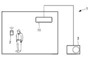
- FIG. 1 is a diagram showing a schematic configuration of an air conditioner according to an embodiment of the present disclosure
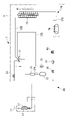
- FIG. 1 is a diagram showing a refrigerant circuit of an air conditioner according to an embodiment of the present disclosure
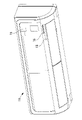
- FIG. 1 is a diagram showing the appearance of an indoor unit of an air conditioner according to an embodiment of the present disclosure
- FIG. Fig. 2 is a functional block diagram showing functions of a control device in the air conditioner according to the embodiment of the present disclosure
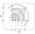
- FIG. 4 is a diagram showing an example of reference information held by a control device according to an embodiment of the present disclosure
- FIG. 4 is a diagram showing an example of reference information held by a control device according to an embodiment of the present disclosure
- FIG. 4 is a diagram showing an example of reference information held by a control device according to an embodiment of the present disclosure
- FIG. 1 is a diagram showing a schematic configuration of an air conditioner according to an embodiment of the present disclosure
- FIG. 1 is a diagram showing a refrigerant circuit of an air conditioner according to an embodiment of the
- the indoor unit 11 is arranged, for example, in a room (to be air-conditioned) such as a facility, and performs heat exchange between a refrigerant flowing through a refrigerant circuit described later and indoor air.
- the refrigerant heat-exchanged in the indoor unit 11 is supplied to the outdoor unit 3 through the refrigerant circuit.
- the number of indoor units 11 connected to one outdoor unit 3 can be changed as appropriate.
- FIG. 3 is a diagram showing the appearance of the indoor unit 11.
- the indoor unit 11 is provided with a measurement unit (hereinafter referred to as a “CO2 sensor”) 15 for measuring the concentration of carbon dioxide, a motion sensor 18 and a display unit 16 .
- the CO2 sensor 15 is a measuring instrument that measures the concentration of carbon dioxide in the room to be air-conditioned
- the human sensor 18 is a detector that detects the presence or absence of people (the number of people) in the room to be air-conditioned. .
- the detection results of the CO2 sensor 15 and the human sensor 18 are used by the control device 20, which will be described later.
- the indoor unit 11 is also provided with a temperature sensor and a humidity sensor for detecting indoor temperature and humidity.
- the display unit 16 displays various information under the control of the control device 20, which will be described later.
- the devices on the outdoor unit 3 side are connected in a known manner through refrigerant pipes such as a discharge pipe 37A, a gas pipe 37B, a liquid pipe 37C, and a suction pipe 37E to form an outdoor refrigerant circuit 39.
- the outdoor unit 3 is provided with an outdoor fan 41 that blows outside air to the outdoor heat exchanger 19 .
- the cooling operation is performed as follows.
- the high-temperature, high-pressure refrigerant gas compressed by the compressor 13 is discharged to the discharge pipe 37A and supplied to the four-way switching valve 17 via the muffler 12 .
- the refrigerant gas is circulated to the gas pipe 37B side by the four-way switching valve 17, is heat-exchanged with the outside air blown by the outdoor fan 41 in the outdoor heat exchanger 19, and is condensed and liquefied.
- This liquid refrigerant is temporarily stored in the receiver 26 via the liquid pipe 37C.
- the liquid refrigerant whose circulation amount is adjusted by the receiver 26 is adiabatically expanded by the expansion valve 49 via the liquid side pipe 7 .
- This liquid refrigerant is led out from the outdoor unit 3 through the strainer 14 and the liquid side operation valve 35 and supplied to the indoor unit 11 .
- the liquid refrigerant flows into the indoor heat exchanger 47 in the indoor unit 11 .
- the indoor heat exchanger 47 heat is exchanged between the indoor air circulated by the indoor fan 51 and the refrigerant, and the indoor air is cooled and used for indoor cooling.
- the refrigerant is gasified, passes through the gas side pipe 5 and the gas side operation valve 33, reaches the four-way switching valve 17, and is introduced into the accumulator 31 through the suction pipe 37E.
- the accumulator 31 separates the liquid contained in the refrigerant gas and sucks only the gas into the compressor 13 . This refrigerant is compressed again in the compressor 13, and cooling operation is performed by repeating the above cycle.
- the heating operation is performed as follows.
- the high-temperature, high-pressure refrigerant gas compressed by the compressor 13 is discharged to the discharge pipe 37A, supplied to the four-way switching valve 17 via the muffler 12, and then circulated to the gas side pipe 5 by the four-way switching valve 17. .
- This refrigerant is led out from the outdoor unit 3 through the gas side operation valve 33 and introduced into the indoor unit 11 .
- the refrigerant returned to the outdoor unit 3 flows into the receiver 26 through the liquid side operation valve 35, the strainer 14, and the expansion valve 49, and is temporarily stored to adjust the circulation amount.
- This liquid refrigerant flows into the outdoor heat exchanger 19 via the liquid pipe 37C.
- the outdoor heat exchanger 19 heat is exchanged between the outside air blown from the outdoor fan 41 and the refrigerant, and the refrigerant absorbs heat from the outside air and evaporates.
- This refrigerant is introduced from the outdoor heat exchanger 19 into the accumulator 31 through the gas pipe 37B, the four-way switching valve 17, and the suction pipe 37E.
- the accumulator 31 separates the liquid contained in the refrigerant gas, and only the gas is sucked into the compressor 13 and compressed again in the compressor 13 . Heating operation is performed by repeating the above cycle.
- the control device 20 controls the air conditioner 1 .
- the control device 20 evaluates comfort in the room to be air-conditioned. Then, comfort improvement control is performed based on the comfort evaluation result.
- the acquisition unit 21 acquires temperature information, humidity information, and carbon dioxide concentration information in the room to be air-conditioned. Specifically, the acquisition unit 21 acquires detection results of temperature, humidity, and carbon dioxide concentration as indoor environmental information from the temperature sensor, humidity sensor, and CO2 sensor 15 provided in the indoor unit 11 . It should be noted that any information that can indirectly estimate temperature, humidity, and carbon dioxide concentration may be acquired as temperature information, humidity information, and carbon dioxide concentration information without being acquired directly. In the following description, since values are obtained directly from each sensor, it is assumed that temperature is used as temperature information, humidity is used as humidity information, and carbon dioxide concentration is used as carbon dioxide concentration information.
- the acquisition unit 21 acquires the current indoor environment information. Then, it outputs the acquired information to the evaluation unit 22 .
- the evaluation unit 22 evaluates the user's comfort in the room based on temperature information (temperature), humidity information (humidity), and concentration information (carbon dioxide concentration). Specifically, the evaluation unit 22 evaluates comfort based on a comfortable range of temperature and humidity that is preset in correspondence with the concentration of carbon dioxide. That is, it is possible to evaluate comfort more effectively by considering temperature, humidity, and carbon dioxide concentration.
- the evaluation unit 22 has information (reference information) indicating a comfortable range in which temperature, humidity, and carbon dioxide concentration are associated. Even if the information is not stored in the evaluation unit 22, it may be obtained by downloading from another information processing device.
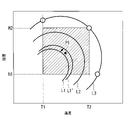
- FIG. 5 shows an example of reference information (graph) that the evaluation unit 22 has.
- a range assumed to ensure user comfort is set for temperature and humidity (relative humidity). That is, the comfort is secured in the temperature range from T1 to T2 with respect to the temperature, and the comfort is secured in the temperature range from H1 to H2 with respect to the humidity. That is, in terms of temperature and humidity, the ranges enclosed by T1 to T2 and H1 to H2 are comfortable ranges.
- T1 is 17° C.
- T2 is 28° C.
- H1 is 40%
- H2 is 70%.
- the comfortable range of temperature and humidity may be set, for example, based on the indoor air environment standards in the Building Management Act, or it may be set arbitrarily as a range of temperature and humidity that ensures comfort. good.
- the reference information shows boundary lines (contour lines) that indicate the boundaries of the temperature and humidity ranges in which the user may feel uncomfortable with respect to the carbon dioxide concentration.
- a boundary line L1, a boundary line L2, and a boundary line L3 are shown, and the corresponding carbon dioxide concentrations are highest at the boundary line L1, second highest at the boundary line L2, and lowest at the boundary line L3.
- the carbon dioxide concentration corresponding to the boundary line L1 is 1500 ppm
- the carbon dioxide concentration corresponding to the boundary line L2 is 1000 ppm
- the carbon dioxide concentration corresponding to the boundary line L3 is 400 ppm.
- the area of R1 in FIG. 5 is the comfort range.
- the concentration of carbon dioxide corresponds to the boundary line L1
- the temperature is t1
- the humidity is h1
- the indoor environment is within the comfortable range and is therefore evaluated as comfortable.
- the concentration of carbon dioxide corresponds to the boundary line L1
- the temperature is t2
- the humidity is h2
- the indoor environment is not within the comfortable range and is evaluated as uncomfortable.
- FIG. 5 is an example of reference information, and can be appropriately set based on the relationship between temperature, humidity, and carbon dioxide concentration.
- the shape of the boundary line is an arc
- the arc is maximum for humidity at T1
- the arc is maximum for temperature at H1
- each boundary line for carbon dioxide concentration is a 1/4 arc. (i.e., the boundaries set for the temperature and humidity comfort ranges are in the shape of quarter arcs).
- the reference information has a shape such as that shown in FIG. 6, for example.
- the evaluation method is not limited to the evaluation of comfort or discomfort with respect to the boundary line, but the area containing the boundary line (for example, the area surrounded by parallel lines with a certain distance on both sides of the line with respect to the boundary line) ), and if it is outside in the direction where the temperature and humidity are higher than the area, the discomfort is high, if it is inside, the discomfort is low, and if it is outside in the direction where the temperature and humidity are low, it is comfortable. It may be evaluated.
- the notification unit 23 notifies the user of the comfort evaluation result. Specifically, the notification unit 23 causes the display unit 16 in the indoor unit 11 to display the comfort evaluation result, and notifies the user. Note that the notification unit 23 may cause the remote control 2 to display, or may cause the user's portable terminal (for example, a smartphone or the like) to display. When displaying on the mobile terminal of the user, a communication network (public notification network) such as Wi-Fi may be used.
- the method of notification by the notification unit 23 is not limited to the visual method on the display unit 16, and any method that can be recognized by the user (for example, an auditory method) can be applied.
- the comfort evaluation result is displayed on the display unit 16 so as to indicate comfort or discomfort. For example, “comfortable” is displayed as “blue”, and “unpleasant” is displayed as “red”.
- “comfortable” is displayed as “blue”
- “unpleasant” is displayed as “red”.
- the display method is not limited to the above, and any method that can be recognized by the user can be applied. For example, a method of displaying evaluation results in stages, a method of displaying points, and the like can be applied.
- the notification unit 23 notifies the user of the outdoor environment information.
- the outdoor environment information includes at least one of outdoor temperature information, pollen information, and particulate matter (PM2.5) information.
- the display of the comfort rating may prompt the user to ventilate. However, ventilation may allow hot air from the outside, pollen, etc. to enter the room and reduce comfort. Therefore, by notifying the user of outdoor temperature information, pollen information, and particulate matter information as outdoor environment information, the user can more efficiently determine whether or not to perform ventilation according to the comfort evaluation. It becomes possible.
- the method of notifying the outdoor environment information may be displayed on the indoor unit 11 or the remote controller 2, or may be displayed on the user's mobile terminal (for example, a smartphone, etc.).
- the control unit 24 controls at least one of indoor air-conditioning air volume, target temperature, and target humidity based on the comfort evaluation result. Specifically, when the evaluation unit 22 evaluates that the comfort is poor (unpleasant), the control unit 24 performs comfort improvement control to improve the indoor environment.
- the control targets are the air-conditioning air volume, the target temperature, and the target humidity, but comfort improvement control may be performed with at least one of them as the control target.
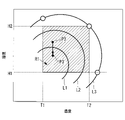
- the control unit 24 increases the air-conditioning air volume to promote the flow of air in the room, agitate the carbon dioxide, and partially reduce the carbon dioxide concentration. to prevent it from becoming too high.
- the rotation speed of the indoor fan 51 is increased, for example, and the air volume ventilated indoors is increased.
- the air conditioner 1 has a ventilation function (a function of discharging the inside air to the outside and taking in the outside air into the room), the ventilation function is used to reduce the carbon dioxide concentration in the room, and the same as in FIG. comfort may be improved.
- a ventilation function a function of discharging the inside air to the outside and taking in the outside air into the room
- the controller 24 lowers the target temperature and changes the indoor environment to the point P2'. Since the point P2' is within the comfort range, the user's comfort is improved.
- the target temperature When changing the target temperature, the target temperature may be lowered by a preset fixed value, or the target temperature may be lowered so that the indoor environment is within a comfortable range based on the reference information. may be
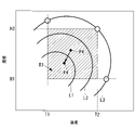
- the controller 24 lowers the target temperature and the target humidity to change the indoor environment to the point P4'. Since the point P4' is within the comfort range, the user's comfort is improved.
- air-conditioning air volume, target temperature, and target humidity may be controlled simultaneously.
- the prediction unit 25 predicts the concentration increase of carbon dioxide based on the number of users in the room. As the number of people in the room increases, the concentration of carbon dioxide in the room increases significantly, which tends to cause deterioration of the indoor environment (easily reduce comfort). For this reason, the prediction unit 25 predicts an increase in carbon dioxide concentration in order to suppress deterioration of comfort.
- the estimation of the increase in the concentration of carbon dioxide may also be made in consideration of the volume of the room to be air-conditioned.
- the prediction unit 25 estimates the carbon dioxide concentration after a predetermined period of time has passed, and outputs it to the evaluation unit 22 .
- the predetermined time can be set arbitrarily, it is, for example, one hour later.
- the evaluation unit 22 evaluates comfort after a predetermined period of time based on the temperature information, the humidity information, and the prediction result (the carbon dioxide concentration after the predetermined period of time has passed). That is, the evaluation unit 22 uses the prediction result of the prediction unit 25 instead of the carbon dioxide concentration information acquired from the CO2 sensor 15 to evaluate the comfort after a predetermined time has elapsed.
- the method of evaluating comfort is the same as described above.
- the evaluation unit 22 can evaluate the comfort after the predetermined time has passed.
- the evaluation result is used by the notification unit 23 and the control unit 24 to notify the user of the comfort after the elapse of the predetermined time, and the comfort improvement control is performed based on the comfort after the elapse of the predetermined time.
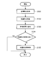
- the flow shown in FIG. 11 is repeatedly executed at a predetermined control cycle when the air conditioner 1 is activated.
- temperature information, humidity information, and carbon dioxide concentration information are acquired (S101).
- comfort improvement control is performed (S105).
- the comfort improvement control is control for improving comfort by controlling at least one of indoor air-conditioning air volume, target temperature, and target humidity.
- the order of the processing of S103 and the processing of S104 and S105 may be changed, or one of them may be performed.
- control device for an air conditioner the air conditioner, the air conditioning method, and the air conditioning program according to the present embodiment
- temperature information, humidity Based on the information and carbon dioxide concentration information, not only the temperature and humidity but also the carbon dioxide concentration in the room can be taken into consideration, and the comfort evaluation can be performed more effectively.
- the user can recognize the indoor environment (visualization of the degree of air pollution) based on the comfort evaluation results that take into account the concentration of carbon dioxide. For example, when it is notified that comfort is poor, the user can improve the indoor environment by ventilating the room.
- Air conditioner 2 Remote controller 3: Outdoor unit 5: Gas side pipe 7: Liquid side pipe 11: Indoor unit 12: Muffler 13: Compressor 14: Strainer 15: CO2 sensor 16: Display unit 17: Four-way switching valve 18 : Human sensor 19 : Outdoor heat exchanger 20 : Control device 21 : Acquisition unit 22 : Evaluation unit 23 : Notification unit 24 : Control unit 25 : Prediction unit 26 : Receiver 31 : Accumulator 33 : Gas side operation valve 35 : Liquid side Operation valve 37A: Discharge pipe 37B: Gas pipe 37C: Liquid pipe 37E: Suction pipe 39: Outdoor refrigerant circuit 41: Outdoor fan 45: Refrigeration cycle 47: Indoor heat exchanger 49: Expansion valve 51: Indoor fan
Landscapes
- Engineering & Computer Science (AREA)
- Signal Processing (AREA)
- Chemical & Material Sciences (AREA)
- Combustion & Propulsion (AREA)
- Mechanical Engineering (AREA)
- General Engineering & Computer Science (AREA)
- Physics & Mathematics (AREA)
- Fuzzy Systems (AREA)
- Mathematical Physics (AREA)
- Air Conditioning Control Device (AREA)
Abstract
Description
図1は、本開示の一実施形態に係る空気調和装置1の概略構成を示す図である。図1に示すように、本実施形態に係る空気調和装置1は、室外機3と、室内機11とを主な構成として備えている。本実施形態では、図1に示すように、1台の室外機3に対して1台の室内機11が接続される場合について説明するが、室内機11の台数については上記構成に限定されない。
図2には、本実施形態に係る空気調和装置1の冷媒回路図が示されている。空気調和装置1は、室外機3と、室内機11とを備えている。なお、図2に示す冷媒回路は一例であり、冷媒回路であれば図2に示す構成に限定されない。
室外機3には、室外熱交換器19に対して外気を送風する室外ファン41が設けられている。
圧縮機13で圧縮された高温高圧の冷媒ガスは、吐出配管37Aに吐出され、マフラ12を介して四方切換弁17に供給される。
その後、冷媒ガスは、四方切換弁17によりガス配管37B側に循環され、室外熱交換器19で室外ファン41により送風される外気と熱交換されて凝縮液化される。
この液冷媒は、液配管37Cを介してレシーバ26にいったん貯留される。
この液冷媒は、ストレーナ14及び液側操作弁35を経て室外機3から導出され、室内機11へ供給される。
アキュムレータ31では、冷媒ガス中に含まれている液分が分離され、ガス分のみが圧縮機13へと吸入される。
この冷媒は、圧縮機13において再び圧縮され、以上のサイクルを繰り返すことによって冷房運転が行われる。
圧縮機13により圧縮された高温高圧の冷媒ガスは、吐出配管37Aに吐出され、マフラ12を介して四方切換弁17に供給された後、四方切換弁17によりガス側配管5側に循環される。
この冷媒は、ガス側操作弁33を経て室外機3から導出され、室内機11へと導入される。
室内熱交換器47で凝縮された液冷媒は、室外機3に戻される。
この液冷媒は、液配管37Cを介して室外熱交換器19へと流入される。
この冷媒は、室外熱交換器19からガス配管37B、四方切換弁17、吸入配管37Eを経てアキュムレータ31に導入される。アキュムレータ31では、冷媒ガス中に含まれている液分が分離されてガス分のみが圧縮機13へと吸入され、圧縮機13において再び圧縮される。以上のサイクルを繰り返すことによって暖房運転が行われる。
制御装置20は、空気調和装置1の制御を行う。制御装置20では、空調対象である室内の快適性を評価する。そして、快適性の評価結果に基づいて、快適性改善制御を行う。
空調対象である室内においては、空間内において部分的(局所的)に二酸化炭素濃度が高くなってしまう可能性がある。特に、ユーザの周囲領域に二酸化炭素濃度が高くなっている場合には、ユーザは不快と感じやすい。このため、制御部24では、快適性の評価結果が不快と判定された場合に、空調風量を強くして、室内の空気の流れを促し、二酸化炭素を攪拌して、部分的に二酸化炭素濃度が高くなってしまうことを抑制する。なお、空調風量については、例えば室内ファン51の回転数を増加させ、室内に送風される空気量を増加させる。
図5に示すように、二酸化炭素濃度に対して温度を低下させることによって、ユーザは快適性を感じる傾向にある。このため、制御部24では、快適性の評価結果が不快と判定された場合に、目標温度を低下させ、室内温度が低下するよう制御する。なお、空気調和装置1においては、設定された目標温度に追従するように制御が行われる。
図5に示すように、二酸化炭素濃度に対して湿度を低下させることによって、ユーザは快適性を感じる傾向にある。このため、制御部24では、快適性の評価結果が不快と判定された場合に、目標湿度を低下させ、室内湿度が低下するよう制御する。なお、空気調和装置1においては、設定された目標湿度に追従するように制御が行われる。
2 :リモコン
3 :室外機
5 :ガス側配管
7 :液側配管
11 :室内機
12 :マフラ
13 :圧縮機
14 :ストレーナ
15 :CO2センサ
16 :表示部
17 :四方切換弁
18 :人感センサ
19 :室外熱交換器
20 :制御装置
21 :取得部
22 :評価部
23 :通知部
24 :制御部
25 :予測部
26 :レシーバ
31 :アキュムレータ
33 :ガス側操作弁
35 :液側操作弁
37A :吐出配管
37B :ガス配管
37C :液配管
37E :吸入配管
39 :室外側冷媒回路
41 :室外ファン
45 :冷凍サイクル
47 :室内熱交換器
49 :膨張弁
51 :室内ファン
Claims (10)
- 空調対象である室内の温度情報、湿度情報、及び二酸化炭素の濃度情報を取得する取得部と、
前記温度情報、前記湿度情報、及び前記濃度情報に基づいて、前記室内におけるユーザの快適性を評価する評価部と、
を備える空気調和装置の制御装置。 - 前記評価部は、二酸化炭素の濃度に対応して予め設定された温度及び湿度の快適範囲に基づいて、前記快適性を評価する請求項1に記載の空気調和装置の制御装置。
- 前記快適性の評価結果をユーザへ通知する通知部を備える請求項1または2に記載の空気調和装置の制御装置。
- 前記快適性の評価結果に基づいて、前記室内における空調風量、目標温度、及び目標湿度の少なくともいずれか1つの制御対象を制御する制御部を備える請求項1から3のいずれか1項に記載の空気調和装置の制御装置。
- 前記室内にいるユーザの人数に基づいて前記二酸化炭素の濃度上昇を予測する予測部を備え、
前記評価部は、前記濃度情報に代えて前記予測の結果を用い、所定時間経過後における前記快適性を評価する請求項1から4のいずれか1項に記載の空気調和装置の制御装置。 - 前記通知部は、室外環境情報をユーザへ通知する請求項3に記載の空気調和装置の制御装置。
- 前記室外環境情報は、外気温情報、花粉情報、及び微粒子状物質情報の少なくとも1つを含む請求項6に記載の空気調和装置の制御装置。
- 冷媒回路と、
請求項1から7のいずれか1項に記載の空気調和装置の制御装置と
を有する空気調和装置。 - 空調対象である室内の温度情報、湿度情報、及び二酸化炭素の濃度情報を取得する取得工程と、
前記温度情報、前記湿度情報、及び前記濃度情報に基づいて、前記室内におけるユーザの快適性を評価する評価工程と、
を有する空気調和方法。 - 空調対象である室内の温度情報、湿度情報、及び二酸化炭素の濃度情報を取得する取得処理と、
前記温度情報、前記湿度情報、及び前記濃度情報に基づいて、前記室内におけるユーザの快適性を評価する評価処理と、
をコンピュータに実行させるための空気調和プログラム。
Priority Applications (2)
| Application Number | Priority Date | Filing Date | Title |
|---|---|---|---|
| AU2021429884A AU2021429884A1 (en) | 2021-02-24 | 2021-10-27 | Air conditioner control device, air conditioner, air conditioning method, and air conditioning program |
| EP21928026.0A EP4283205A4 (en) | 2021-02-24 | 2021-10-27 | AIR CONDITIONING CONTROL DEVICE, AIR CONDITIONING, AIR CONDITIONING METHOD AND AIR CONDITIONING PROGRAM |
Applications Claiming Priority (2)
| Application Number | Priority Date | Filing Date | Title |
|---|---|---|---|
| JP2021-027325 | 2021-02-24 | ||
| JP2021027325A JP7767015B2 (ja) | 2021-02-24 | 2021-02-24 | 空気調和装置の制御装置及び空気調和装置、並びに空気調和方法、並びに空気調和プログラム |
Publications (1)
| Publication Number | Publication Date |
|---|---|
| WO2022180931A1 true WO2022180931A1 (ja) | 2022-09-01 |
Family
ID=83047963
Family Applications (1)
| Application Number | Title | Priority Date | Filing Date |
|---|---|---|---|
| PCT/JP2021/039653 Ceased WO2022180931A1 (ja) | 2021-02-24 | 2021-10-27 | 空気調和装置の制御装置及び空気調和装置、並びに空気調和方法、並びに空気調和プログラム |
Country Status (4)
| Country | Link |
|---|---|
| EP (1) | EP4283205A4 (ja) |
| JP (1) | JP7767015B2 (ja) |
| AU (1) | AU2021429884A1 (ja) |
| WO (1) | WO2022180931A1 (ja) |
Cited By (1)
| Publication number | Priority date | Publication date | Assignee | Title |
|---|---|---|---|---|
| WO2024070491A1 (ja) * | 2022-09-29 | 2024-04-04 | 三菱重工サーマルシステムズ株式会社 | 空気調和システムの室内機、空気調和システム、制御装置、空気調和システムの室内機の制御方法、プログラム |
Citations (4)
| Publication number | Priority date | Publication date | Assignee | Title |
|---|---|---|---|---|
| JP2011089682A (ja) * | 2009-10-21 | 2011-05-06 | Hitachi Ltd | エリア内環境制御システム及びエリア内環境制御方法 |
| JP2011196683A (ja) * | 2011-06-06 | 2011-10-06 | Toshiba Corp | データ処理装置及び二酸化炭素濃度測定用センサーシステム |
| WO2016185630A1 (ja) * | 2015-05-18 | 2016-11-24 | 三菱電機株式会社 | 室内環境モデル作成装置 |
| JP2019068238A (ja) * | 2017-09-29 | 2019-04-25 | 株式会社富士通ゼネラル | 空調システム、空調機器、通信方法及びデータ取得表示プログラム |
Family Cites Families (14)
| Publication number | Priority date | Publication date | Assignee | Title |
|---|---|---|---|---|
| JP3852463B2 (ja) * | 2004-09-28 | 2006-11-29 | ダイキン工業株式会社 | 環境ナビゲーション装置及び環境ナビゲーションプログラム |
| JP4836967B2 (ja) * | 2008-01-23 | 2011-12-14 | 株式会社東芝 | 空調制御支援画面生成装置、空調制御支援画面生成方法、および空調監視システム |
| JP5532153B1 (ja) * | 2013-01-10 | 2014-06-25 | ダイキン工業株式会社 | 空気調和システム |
| JP6111499B2 (ja) * | 2013-02-13 | 2017-04-12 | パナソニックIpマネジメント株式会社 | 空気調和システム、指示装置 |
| US9784464B2 (en) * | 2013-04-22 | 2017-10-10 | Mitsubishi Electric Corporation | Air-conditioning control system and air-conditioning control method |
| JP6169534B2 (ja) * | 2014-05-29 | 2017-07-26 | シャープ株式会社 | メッセージ通知装置、メッセージ通知方法、メッセージ出力装置、メッセージ出力システム、携帯機器、自動車、空調機器、及び、プログラム |
| DE112014006809T5 (de) * | 2014-07-16 | 2017-03-30 | Mitsubishi Electric Corporation | Klimatisierungssteuerung, Klimatisierungssteuerungsverfahren und Programm |
| KR102116160B1 (ko) * | 2014-11-28 | 2020-05-27 | 케이웨더(주) | 통합 실내 환경 관리 장치 |
| JP2017096584A (ja) * | 2015-11-26 | 2017-06-01 | パナソニックIpマネジメント株式会社 | 空調システム及びプログラム |
| TWI598541B (zh) * | 2016-01-19 | 2017-09-11 | 台達電子工業股份有限公司 | 空調的空氣側設備的能源最佳化系統及能源最佳化方法 |
| JP7037432B2 (ja) * | 2017-07-12 | 2022-03-16 | 三菱電機ビルテクノサービス株式会社 | 快適度表示装置 |
| JP7460876B2 (ja) * | 2019-04-22 | 2024-04-03 | ダイキン工業株式会社 | 空調システム |
| JP6939841B2 (ja) * | 2019-04-22 | 2021-09-22 | ダイキン工業株式会社 | 空調システム |
| CN111854829A (zh) * | 2019-04-29 | 2020-10-30 | 热映光电股份有限公司 | 环境舒适度的显示方法及其显示装置 |
-
2021
- 2021-02-24 JP JP2021027325A patent/JP7767015B2/ja active Active
- 2021-10-27 AU AU2021429884A patent/AU2021429884A1/en not_active Abandoned
- 2021-10-27 WO PCT/JP2021/039653 patent/WO2022180931A1/ja not_active Ceased
- 2021-10-27 EP EP21928026.0A patent/EP4283205A4/en active Pending
Patent Citations (4)
| Publication number | Priority date | Publication date | Assignee | Title |
|---|---|---|---|---|
| JP2011089682A (ja) * | 2009-10-21 | 2011-05-06 | Hitachi Ltd | エリア内環境制御システム及びエリア内環境制御方法 |
| JP2011196683A (ja) * | 2011-06-06 | 2011-10-06 | Toshiba Corp | データ処理装置及び二酸化炭素濃度測定用センサーシステム |
| WO2016185630A1 (ja) * | 2015-05-18 | 2016-11-24 | 三菱電機株式会社 | 室内環境モデル作成装置 |
| JP2019068238A (ja) * | 2017-09-29 | 2019-04-25 | 株式会社富士通ゼネラル | 空調システム、空調機器、通信方法及びデータ取得表示プログラム |
Non-Patent Citations (1)
| Title |
|---|
| See also references of EP4283205A4 |
Cited By (1)
| Publication number | Priority date | Publication date | Assignee | Title |
|---|---|---|---|---|
| WO2024070491A1 (ja) * | 2022-09-29 | 2024-04-04 | 三菱重工サーマルシステムズ株式会社 | 空気調和システムの室内機、空気調和システム、制御装置、空気調和システムの室内機の制御方法、プログラム |
Also Published As
| Publication number | Publication date |
|---|---|
| AU2021429884A1 (en) | 2023-09-07 |
| EP4283205A1 (en) | 2023-11-29 |
| JP2022128874A (ja) | 2022-09-05 |
| JP7767015B2 (ja) | 2025-11-11 |
| EP4283205A4 (en) | 2024-06-19 |
Similar Documents
| Publication | Publication Date | Title |
|---|---|---|
| CN113574323B (zh) | 空调系统 | |
| JP4720919B2 (ja) | 圧縮機の運転制御装置及びそれを備えた空気調和装置 | |
| JP5532153B1 (ja) | 空気調和システム | |
| KR101502096B1 (ko) | 공기 조화기의 제어 방법 | |
| JP6270996B2 (ja) | 空調装置 | |
| JP5619056B2 (ja) | 空調装置 | |
| JPWO2014041896A1 (ja) | 空気調和システム | |
| JP2012189300A (ja) | 空気調和機 | |
| JP2009216283A (ja) | 空調制御システム | |
| JP2013130384A (ja) | 空気調和装置 | |
| JP6019773B2 (ja) | 空気調和機の制御装置 | |
| JP2016176653A (ja) | 空気調和機 | |
| WO2022180931A1 (ja) | 空気調和装置の制御装置及び空気調和装置、並びに空気調和方法、並びに空気調和プログラム | |
| JP6804272B2 (ja) | 空気調和機の制御装置 | |
| JP7343049B2 (ja) | 空気調和システムおよびデータ提供方法 | |
| JP2020051696A (ja) | 空気調和システムおよび空気調和方法 | |
| CN116839184B (zh) | 全天候调节控制方法及空调器 | |
| JP2004012022A (ja) | 空気調和装置及び空気調和方法 | |
| JP4178906B2 (ja) | 空気調和機および空気調和機の制御方法 | |
| JP7209040B2 (ja) | 空気調和機 | |
| JP7729501B1 (ja) | 室温制御方法、室温制御装置、プログラム、及びこれを備えた室温制御システム | |
| CN119022357B (zh) | 空调 | |
| CN113899059A (zh) | 空气处理系统的控制方法和空气处理系统 | |
| WO2019198277A1 (ja) | 空気調和システム | |
| TWI817412B (zh) | 空調系統、空調系統之控制方法、及空調系統之控制程式 |
Legal Events
| Date | Code | Title | Description |
|---|---|---|---|
| 121 | Ep: the epo has been informed by wipo that ep was designated in this application |
Ref document number: 21928026 Country of ref document: EP Kind code of ref document: A1 |
|
| WWE | Wipo information: entry into national phase |
Ref document number: 2021429884 Country of ref document: AU |
|
| ENP | Entry into the national phase |
Ref document number: 2021928026 Country of ref document: EP Effective date: 20230822 |
|
| ENP | Entry into the national phase |
Ref document number: 2021429884 Country of ref document: AU Date of ref document: 20211027 Kind code of ref document: A |
|
| NENP | Non-entry into the national phase |
Ref country code: DE |