WO2022181032A1 - 濾過装置 - Google Patents
濾過装置 Download PDFInfo
- Publication number
- WO2022181032A1 WO2022181032A1 PCT/JP2021/048111 JP2021048111W WO2022181032A1 WO 2022181032 A1 WO2022181032 A1 WO 2022181032A1 JP 2021048111 W JP2021048111 W JP 2021048111W WO 2022181032 A1 WO2022181032 A1 WO 2022181032A1
- Authority
- WO
- WIPO (PCT)
- Prior art keywords
- tank
- liquid
- plate
- flow path
- pump
- Prior art date
- Legal status (The legal status is an assumption and is not a legal conclusion. Google has not performed a legal analysis and makes no representation as to the accuracy of the status listed.)
- Ceased
Links
Images


Classifications
-
- B—PERFORMING OPERATIONS; TRANSPORTING
- B01—PHYSICAL OR CHEMICAL PROCESSES OR APPARATUS IN GENERAL
- B01D—SEPARATION
- B01D21/00—Separation of suspended solid particles from liquids by sedimentation
- B01D21/24—Feed or discharge mechanisms for settling tanks
- B01D21/245—Discharge mechanisms for the sediments
-
- B—PERFORMING OPERATIONS; TRANSPORTING
- B01—PHYSICAL OR CHEMICAL PROCESSES OR APPARATUS IN GENERAL
- B01D—SEPARATION
- B01D21/00—Separation of suspended solid particles from liquids by sedimentation
- B01D21/02—Settling tanks with single outlets for the separated liquid
-
- B—PERFORMING OPERATIONS; TRANSPORTING
- B01—PHYSICAL OR CHEMICAL PROCESSES OR APPARATUS IN GENERAL
- B01D—SEPARATION
- B01D21/00—Separation of suspended solid particles from liquids by sedimentation
-
- B—PERFORMING OPERATIONS; TRANSPORTING
- B01—PHYSICAL OR CHEMICAL PROCESSES OR APPARATUS IN GENERAL
- B01D—SEPARATION
- B01D21/00—Separation of suspended solid particles from liquids by sedimentation
- B01D21/24—Feed or discharge mechanisms for settling tanks
-
- B—PERFORMING OPERATIONS; TRANSPORTING
- B01—PHYSICAL OR CHEMICAL PROCESSES OR APPARATUS IN GENERAL
- B01D—SEPARATION
- B01D21/00—Separation of suspended solid particles from liquids by sedimentation
- B01D21/24—Feed or discharge mechanisms for settling tanks
- B01D21/2433—Discharge mechanisms for floating particles
-
- B—PERFORMING OPERATIONS; TRANSPORTING
- B01—PHYSICAL OR CHEMICAL PROCESSES OR APPARATUS IN GENERAL
- B01D—SEPARATION
- B01D21/00—Separation of suspended solid particles from liquids by sedimentation
- B01D21/26—Separation of sediment aided by centrifugal force or centripetal force
-
- B—PERFORMING OPERATIONS; TRANSPORTING
- B04—CENTRIFUGAL APPARATUS OR MACHINES FOR CARRYING-OUT PHYSICAL OR CHEMICAL PROCESSES
- B04C—APPARATUS USING FREE VORTEX FLOW, e.g. CYCLONES
- B04C1/00—Apparatus in which the main direction of flow follows a flat spiral ; so-called flat cyclones or vortex chambers
-
- B—PERFORMING OPERATIONS; TRANSPORTING
- B04—CENTRIFUGAL APPARATUS OR MACHINES FOR CARRYING-OUT PHYSICAL OR CHEMICAL PROCESSES
- B04C—APPARATUS USING FREE VORTEX FLOW, e.g. CYCLONES
- B04C9/00—Combinations with other devices, e.g. fans, expansion chambers, diffusors, water locks
-
- B—PERFORMING OPERATIONS; TRANSPORTING
- B23—MACHINE TOOLS; METAL-WORKING NOT OTHERWISE PROVIDED FOR
- B23Q—DETAILS, COMPONENTS, OR ACCESSORIES FOR MACHINE TOOLS, e.g. ARRANGEMENTS FOR COPYING OR CONTROLLING; MACHINE TOOLS IN GENERAL CHARACTERISED BY THE CONSTRUCTION OF PARTICULAR DETAILS OR COMPONENTS; COMBINATIONS OR ASSOCIATIONS OF METAL-WORKING MACHINES, NOT DIRECTED TO A PARTICULAR RESULT
- B23Q11/00—Accessories fitted to machine tools for keeping tools or parts of the machine in good working condition or for cooling work; Safety devices specially combined with or arranged in, or specially adapted for use in connection with, machine tools
- B23Q11/10—Arrangements for cooling or lubricating tools or work
-
- B—PERFORMING OPERATIONS; TRANSPORTING
- B01—PHYSICAL OR CHEMICAL PROCESSES OR APPARATUS IN GENERAL
- B01D—SEPARATION
- B01D21/00—Separation of suspended solid particles from liquids by sedimentation
- B01D21/0009—Settling tanks making use of electricity or magnetism
-
- Y—GENERAL TAGGING OF NEW TECHNOLOGICAL DEVELOPMENTS; GENERAL TAGGING OF CROSS-SECTIONAL TECHNOLOGIES SPANNING OVER SEVERAL SECTIONS OF THE IPC; TECHNICAL SUBJECTS COVERED BY FORMER USPC CROSS-REFERENCE ART COLLECTIONS [XRACs] AND DIGESTS
- Y02—TECHNOLOGIES OR APPLICATIONS FOR MITIGATION OR ADAPTATION AGAINST CLIMATE CHANGE
- Y02P—CLIMATE CHANGE MITIGATION TECHNOLOGIES IN THE PRODUCTION OR PROCESSING OF GOODS
- Y02P70/00—Climate change mitigation technologies in the production process for final industrial or consumer products
- Y02P70/10—Greenhouse gas [GHG] capture, material saving, heat recovery or other energy efficient measures, e.g. motor control, characterised by manufacturing processes, e.g. for rolling metal or metal working
Definitions
- the present invention relates to a filtering device.
- Grinding fluid, cutting fluid, and coolant are used for the purpose of improving processing accuracy, extending the life of tools used, and promoting the discharge of chips and metal powder when grinding or cutting metal materials, etc., using machine tools.
- a variety of liquids are used. These liquids are discharged from the machine tool while containing foreign matter such as chips and metal powder generated by machining.
- the liquid discharged from the machine tool is used by separating and removing foreign matter such as chips, and then returning it to the machine tool again. Therefore, various devices are known for recovering the liquid discharged from the machine tool and for separating and removing the foreign matter.
- Patent Document 1 when a liquid containing foreign matter flows into a filtration tank, the liquid flows along curved plates provided at the corners of the filtration tank, generating a whirlpool inside the filtration tank.
- a filtering device is disclosed in which the contaminants are collected in the central portion of the filtering tank by the vortex, and the collected contaminants are sucked and discharged by a pump.
- This filtration device has the advantage of being able to generate a vortex without installing a device for generating a vortex in the filtration tank or forming the filtration tank itself into a cylindrical shape.
- a filtering device includes a tank portion having a first tank into which liquid containing foreign matter flows, and a central portion of the first tank, which discharges the liquid stored in the first tank. and a pump that
- the first tank covers a bottom surface, four side surfaces connected to the bottom surface, four corners each connected to the bottom surface and two of the four side surfaces, and the four corners. and four inclined planes.
- the four inclined surfaces are inclined so as to approach the bottom surface as they go from the connecting portion where the two side surfaces are connected toward the central portion, and the liquid flowing into the first tank causes the liquid to flow into the first tank.
- a vortex is generated to collect the foreign matter in the central portion of the first tank and discharge it by the pump.
- a filtering device includes a first processing device that processes a liquid containing foreign matter; a tank section that includes a first tank into which the liquid processed by the first processing device flows; and a pump provided in the center of the tank for discharging the liquid stored in the first tank.
- the first tank is provided along a bottom surface, a plurality of side surfaces connected to the bottom surface, and a first side surface that is one of the plurality of side surfaces. and a first flow path through which the liquid flows.
- the first flow path has a bottom plate that inclines from an upstream located on an outlet side of the first processing device toward a downstream located on the bottom side, and that inclines toward the bottom as it goes toward the first side. have.
- the liquid flowing into the first tank causes a swirling current in the first tank to collect the foreign matter in the central portion of the first tank and discharge it by the pump.
- FIG. 1 is a schematic side view of a filtering device according to one embodiment
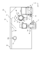
- FIG. FIG. 2 is a schematic plan view of a filtering device according to one embodiment.
- FIG. 3 is a schematic perspective view of a tank portion included in the filtering device.
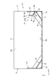
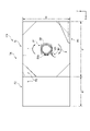
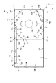
- FIG. 4 is a schematic plan view of a tank portion included in the filtering device.
- 5 is a schematic cross-sectional view of the tank portion taken along line AA in FIG. 4.
- FIG. 6 is a schematic cross-sectional view of the tank portion taken along line BB in FIG. 4.
- FIG. 9 is a schematic cross-sectional view of the tank portion taken along line BB in FIG. 4.
- FIG. 10 is a schematic perspective view of the second channel.
- FIG. 11 is a schematic cross-sectional view of the tank portion taken along line DD in FIG.
- FIG. 12 is a schematic perspective view of the first tank side of the filtering device. 13 is an enlarged view showing the vicinity of the plate member in FIG. 12.
- FIG. 14 is a schematic plan view of the plate member in FIG. 13.
- FIG. 15 is a schematic plan view showing another example of the plate members provided in the first tank.
- FIG. 16 is a schematic side view showing another example of the tank section.
- FIG. 17 is a schematic plan view showing another example of the tank portion.
- FIG. 18 is a schematic plan view showing another example of the second channel.
- FIG. 19 is a plan view showing another example of the position of the first processing device in the first tank.
- FIG. 20 is a plan view showing still another example of the position of the first processing device
- a filtering device for processing foreign matter from a grinding fluid discharged from a machine tool such as a grinder is exemplified.
- Foreign matter includes metal powder, abrasive grains, and the like generated by grinding.
- FIG. 1 is a schematic side view of a filtering device 100 according to this embodiment.
- FIG. 2 is a schematic plan view of the filtering device 100 according to this embodiment.
- the X, Y and Z directions are defined as shown in FIGS. 1 and 2.
- FIG. Both the X direction and the Y direction correspond to horizontal directions parallel to the installation surface of the filtering device 100 and are orthogonal to each other.
- the Z direction corresponds to the vertical direction and is orthogonal to the X and Y directions.
- the direction indicated by the Z-direction arrow is sometimes called upward. Viewing the XY plane defined by the X direction and the Y direction is sometimes referred to as planar viewing.
- the filtering device 100 includes a tank portion TA for storing liquid, a first processing device 1 and a second processing device 2 for processing liquid containing foreign matter, a first pump P1 for discharging the liquid stored in the tank portion TA, and a and a second pump P2.
- “treating” means, for example, separating or removing foreign substances contained in the liquid discharged from the machine tool.
- the tank part TA has a rectangular shape in which the length in the X direction is longer than the length in the Y direction in plan view.
- the tank part TA has a first tank T1 and a second tank T2.
- the tank part TA has a first flow path R1 through which the liquid treated by the first processing apparatus 1 flows, and a second flow path R2 through which the liquid stored in the second tank T2 flows.
- the first flow path R1 and the second flow path R2 are positioned diagonally to the first tank T1 in plan view.
- a vortex is generated in the first tank T1 by the liquid flowing from the first flow path R1 and the second flow path R2.
- a force (centripetal force) directed toward the center of the vortex is exerted on the foreign matter that has flowed into the first tank T1 together with the liquid due to the generated vortex. Therefore, the foreign matter is collected in the central portion CE of the first tank T1 while swirling in the first tank due to the eddy current.
- the central part of the vortex overlaps the central part CE of the first tank T1.
- the central portion CE of the first tank T1 overlaps, for example, the intersection of the diagonal lines of the first tank T1 in plan view.
- an arrow F indicates the flow direction of the vortex.
- a plate member BP having a surface B1 intersecting with the flow direction of the vortex is provided in the vicinity of the first pump P1.
- the first processing device 1 and the second processing device 2 are provided above the first tank T1.
- the first processing device 1 processes the liquid discharged from the machine tool before it flows into the first tank T1.
- the first processing device 1 is, for example, a magnetic separator. When the liquid discharged from the machine tool contains the magnetic material, the magnetic material is processed from the liquid by the first processing device 1 .
- the first processing device 1 has an outlet 1a that opens toward the first tank T1.
- the liquid processed by the first processing device 1 is discharged from the outlet 1a.
- the processing amount of liquid in the first processing device 1 is, for example, 80 L to 360 L per minute.
- the liquid discharged from the first processing device 1 contains foreign substances that could not be processed by the first processing device 1 .
- the second processing device 2 processes the liquid discharged from the first tank T1 before flowing into the second tank T2.
- the second processing device 2 is, for example, a cyclone-type contaminant separating device that removes contaminants contained in liquid by centrifugal force.
- foreign matter that could not be processed in the first processing device 1 is processed from the liquid.
- the foreign matter processed by the second processing device 2 is discharged to a collection tank different from the tank part TA.
- the processing amount of liquid in the second processing device 2 is, for example, 100 L to 300 L per minute.
- the second processing device 2 has an inlet 2a and an outlet 2b.
- the first pump P1 is provided in the central part CE of the first tank T1.
- the second pump P2 is provided near the second flow path R2 in the second tank T2.
- Each of the first pump P1 and the second pump P2 has suction ports P1a and P2a and discharge ports P1b and P2b located on the sides of bottom surfaces 10A and 10B, which will be described later.
- the foreign substances collected in the central portion CE of the first tank T1 are sucked together with the liquid from the suction port P1a of the first pump P1 and discharged from the discharge port P1b.
- the discharge port P1b of the first pump P1 is connected to the inlet 2a of the second processing device 2 by a hose H1.
- the outlet 2b of the second processing device 2 is connected by a hose H2 to an introduction pipe TP provided in the second tank T2.
- the first processing device 1, the second processing device 2, the first pump P1 and the second pump P2 are provided in the tanks T1 and T2 by supports or the like, respectively.
- liquid discharged from a machine tool (not shown) is processed by the first processing device 1 before flowing into the first tank T1.
- the liquid processed by the first processing device 1 is discharged from the outlet 1a.
- the first flow path R1 of the first tank T1 is provided at a position overlapping the outlet 1a in the Z direction.
- the liquid discharged from the outlet 1a flows into the first tank T1 through the first flow path R1.
- Contaminants that could not be processed by the first processing device 1 flow into the first tank T1 together with the liquid.
- the foreign matter flows into the first tank T1, it is collected in the central portion CE of the first tank T1 while swirling due to the vortex in the first tank T1.
- the liquid stored in the first tank T1 is sucked from the suction port P1a of the first pump P1 together with the foreign matter collected in the central portion CE.
- the liquid sucked into the first pump P1 flows from the outlet P1b through the hose H1 into the second processing device 2 from the inlet 2a and is processed.
- the liquid processed by the second processing device 2 flows from the inlet 2b through the hose H2 into the second tank T2 from the introduction pipe TP.
- the liquid processed by the second processing device 2 contains almost no foreign matter.
- the liquid stored in the second tank T2 is sucked from the suction port P2a of the second pump P2 and is sent to the machine tool again through piping (not shown) connected to the discharge port P2b. Further, in the second tank T2, when the liquid level of the liquid stored in the second tank T2 exceeds a specified height, the liquid stored in the second tank T2 flows into the second tank through the second flow path R2. It flows from T2 into the first tank T1.
- FIG. 3 is a schematic perspective view of the tank part TA included in the filtering device 100.
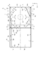
- FIG. 4 is a schematic plan view of the tank part TA included in the filtering device 100.
- FIG. 3 and subsequent figures some elements such as the first pump P1 that constitute the filtering device 100 are omitted.
- the tank part TA is formed by a bottom plate 10, a first side plate 11 and a second side plate 12 arranged in the Y direction, and a third side plate 13 and a fourth side plate 14 arranged in the X direction.
- the first side plate 11 and the second side plate 12 are parallel to the XZ plane defined by the X and Z directions.
- the third side plate 13 and the fourth side plate 14 are parallel to the YZ plane defined by the Y and Z directions.
- the tank part TA further has a partition plate 15 positioned between the third side plate 13 and the fourth side plate 14 and parallel to the third side plate 13 and the fourth side plate 14 .
- the partition plate 15 separates the tank portion TA into a first tank T1 located on the third side plate 13 side and a second tank T2 located on the fourth side plate 14 side.
- the first side plate 11 and the second side plate 12 have the same length in the X direction.
- the third side plate 13, the fourth side plate 14, and the partition plate 15 have the same length in the Y direction.
- the length of the third side plate 13 in the Z direction is shorter than the length of the fourth side plate 14 in the Z direction.
- the length of the fourth side plate 14 in the Z direction is equal to the length of the partition plate 15 in the Z direction.
- the length of the side connected to the third side plate 13 is equal to the length of the third side plate 13 in the Z direction
- the length of the side connected to the fourth side plate 14 is , is equal to the length of the fourth side plate 14 in the Z direction.
- the length in the Z direction of the portion connected to the partition plate 15 is equal to the length of the side connected to the fourth side plate 14 . Therefore, the Z-direction length of the second tank T2 is longer than the Z-direction length of the first tank T1.
- the liquid level of the liquid stored in the second tank T2 can be made higher than the liquid level of the liquid stored in the first tank T1.
- the first tank T1 and the second tank T2 have a rectangular parallelepiped shape with an upper opening, and are arranged in the order of the first tank T1 and the second tank T2 along the X direction.
- the first tank T1 has a square shape with equal lengths in the X direction and the Y direction in plan view.
- the second tank T2 may have a square shape with equal lengths in the X and Y directions, or may have a rectangular shape.
- the size of the tank part TA is appropriately changed depending on the processing amount of the first processing device 1 and the second processing device 2, and the like.
- the X-direction length of the first tank T1 is 500 mm to 2000 mm.
- the Y-direction length of the first tank T1 is 500 mm to 2000 mm.
- the Z-direction length of the first tank T1 is, for example, 200 mm to 500 mm.
- the tank part TA may be formed by bending a plate material. Also, the first tank T1 and the second tank T2 may be formed as separate tanks.
- the bottom plate 10, the side plates 11 to 14 and the partition plate 15 are made of, for example, metal material.
- the first tank T1 includes a bottom surface 10A of the bottom plate 10, a first side surface 11A of the first side plate 11, a second side surface 12A of the second side plate 12, a third side surface 13A of the third side plate 13,
- the partition plate 15 has a fourth side surface 15A on the side of the first tank T1.
- Four of the side surfaces 11A to 13A and 15A are connected to the bottom surface 10A.
- the first side surface 11A faces the second side surface 12A in the Y direction.
- the third side surface 13A faces the fourth side surface 15A in the X direction.
- the first tank T1 has a connection portion J1 where the first side surface 11A and the third side surface 13A are connected, and a corner C1 where the bottom surface 10A and the connection portion J1 (the first side surface 11A and the third side surface 13A) are connected. ing.
- the first tank T1 has a connection portion J2 where the first side surface 11A and the fourth side surface 15A are connected, and a corner C2 where the bottom surface 10A and the connection portion J2 (the first side surface 11A and the fourth side surface 15A) are connected. have.
- the first tank T1 has a connection portion J3 where the second side surface 12A and the fourth side surface 15A are connected, and a corner C3 where the bottom surface 10A and the connection portion J3 (the second side surface 12A and the fourth side surface 15A) are connected.
- the first tank T1 has a connection portion J4 where the second side surface 12A and the third side surface 13A are connected, and a corner C4 where the bottom surface 10A and the connection portion J4 (the second side surface 12A and the third side surface 13A) are connected.
- the connecting portions J1 to J4 are connected at an angle of approximately 90 degrees between the respective side surfaces, but the connecting portions J1 to J4 may be rounded.
- the first tank T1 is provided with four inclined surfaces S1 to S4 covering the corners C1 to C4, respectively.
- the inclined surfaces S1-S4 are formed by plate members 21-24.
- the plate members 21 to 24 are, for example, triangular in shape. Also, when the plate members 21 and 23 come into contact with the first flow path R1 and the second flow path R2, a portion of the triangular plate member may be processed.
- the plate members 21 to 24 are preferably flat plates without curved surfaces. By providing the four plates 21 to 24, each of the corners C1 to C4 can be covered from the center CE side of the first tank T1.
- the plate members 21 to 24 are made of, for example, a metal material, like the bottom plate 10 and the first side plate 11 forming the tank part TA.
- the inclined surface S1 is connected to the bottom surface 10A, the first side surface 11A and the third side surface 13A.
- the inclined surface S2 is connected to the bottom surface 10A, the first side surface 11A and the fourth side surface 15A.
- the inclined surface S3 is connected to the bottom surface 10A, the second side surface 12A and the fourth side surface 15A.
- the inclined surface S4 is connected to the bottom surface 10A, the second side surface 12A and the third side surface 13A. Therefore, liquid does not flow between the corners C1-C4 and the inclined surfaces S1-S4.
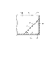
- FIG. 5 is a schematic cross-sectional view of the tank part TA along line AA in FIG.
- the inclined surface S4 covering the corner C4 will be described with reference to FIG.
- the bottom surface 10A and the connecting portion J4 are connected to the corner C4.
- the inclined surface S4 of the plate member 24 is provided in the first tank T1 so as to cover the corner C4 from the central portion CE side of the first tank T1.
- the length of the side connected to the second side surface 12A of the plate member 24 is equal to the length of the side connected to the third side surface 13A.
- the length of the side of the plate member 24 connected to the second side surface 12A may be shorter, longer, or equal to the length of the side connected to the bottom surface 10A.
- the inclined surface S4 is inclined so as to approach the bottom surface 10A from the connecting portion J4 toward the central portion CE of the first tank T1 shown in FIG.
- the angle ⁇ 1 formed by the bottom surface 10A and the plate member 24 is preferably 60 degrees or less, for example.
- the angle ⁇ 1 is appropriately changed according to the throughput of the filtration device 100, the capacity of the first tank T1, and the like.
- the plate member 24 can be provided so that the angle ⁇ 1 is 45 degrees, 50 degrees, and 55 degrees according to the size of the first tank T1. Also, the vertex of the plate member 24 located on the side opposite to the bottom surface 10A is farther from the bottom surface 10A than the liquid surface of the liquid stored in the first tank T1 in, for example, the Z direction. The vertex of the plate member 24 located on the side opposite to the bottom surface 10A may be closer to the bottom surface 10A than the liquid surface of the liquid stored in the first tank T1 in the Z direction.
- the plate member 21 is provided in the first tank T1 so that the inclined surface S1 covers the corner C1.
- the plate member 22 is provided in the first tank T1 so that the inclined surface S2 covers the corner C2.
- the plate member 23 is provided in the first tank T1 so that the inclined surface S3 covers the corner C3.
- the plate members 21 to 23 are provided in the first tank T1 so that the angles formed by the bottom surface 10A and the plate members 21 to 23 are equal to the angle ⁇ 1.
- the liquid flowing through the first tank T1 is less likely to have portions where the flow rate is slow, and the liquid flows through the first tank T1 at a substantially uniform flow rate. can flow inside.
- the inclined surfaces S1 to S4 in the first tank T1 it is possible to improve the rotation efficiency of the liquid in the first tank T1.
- the generated vortex makes it easier for the liquid to flow through the entire first tank T1, and foreign matter is less likely to stay or accumulate in the first tank T1. Also, on the liquid surface, floating substances such as bubbles and foreign matter are less likely to remain.
- the second tank T2 includes a bottom surface 10B of the bottom plate 10, a fifth side surface 11B of the first side plate 11, a sixth side surface 12B of the second side plate 12, and a partition plate 15 on the second tank T2 side (fourth side surface). It has a seventh side surface 15B on the side opposite to the side surface 15A and an eighth side surface 14B on the fourth side plate .
- Four of the side surfaces 11B, 12B, 14B, and 15B are connected to the bottom surface 10B.
- the fifth side surface 11B faces the sixth side surface 12B in the Y direction.
- the seventh side surface 15B faces the eighth side surface 14B in the X direction.
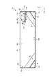
- FIG. 6 is a schematic cross-sectional view of the tank part TA along line BB in FIG.
- FIG. 7 is a schematic perspective view of the first flow path R1.
- FIG. 8 is a schematic cross-sectional view of the tank part TA along line CC in FIG.
- FIG. 6 is a cross section of the tank part TA seen from the direction opposite to the Y direction.
- FIG. 8 is a cross section of the tank part TA seen from the direction opposite to the X direction.
- the first flow path R1 is provided along the first side surface 11A of the first side plate 11 in the first tank T1.
- the first flow path R1 is located on the connection portion J1 side of the first tank T1.
- the first flow path R1 has an end portion R1a located on the third side plate 13 side in the X direction and an end portion R1b located on the partition plate 15 side.
- the exit 1a of the first processing device 1 shown in FIGS. 1 and 2 is located above the end R1a.
- the first flow path R1 is inclined so as to approach the bottom surface 10A from the end R1a toward the end R1b in the X direction.
- the inclination from the end R1a to the end R1b is constant. From another point of view, the length between the end R1a in the Z direction and the bottom surface 10A is longer than the length between the end R1b and the bottom surface 10A.
- the end portion R1b is located closer to the bottom surface 10A in the Z direction than the end portion R1a. The liquid flowing through the first flow path R1 flows from the end R1a toward the end R1b.
- the end R1a side corresponds to the upstream side
- the end R1b side corresponds to the downstream side.
- an arrow FR1 indicates the flow direction of the liquid flowing through the first flow path R1.
- the liquid flowing through the first flow path R1 flows from the third side surface 13A toward the fourth side surface 15A.
- the end portion R1a is connected to the third side surface 13A, and no gap is formed between the end portion R1a and the third side surface 13A.
- the end portion R1b is positioned near the center of the first side surface 11A in the X direction.
- the first flow path R1 has a bottom plate 31 connected to the first side surface 11A, a bottom plate 32 connected to the bottom plate 31, and a side plate 33 connected to the bottom plate 32.
- the bottom plate 31 has a rectangular shape.
- the bottom plate 32 has a triangular shape.
- the length of the bottom plate 32 in the Y direction (width direction) is shortened along the X direction.
- the first flow path R1 is formed in a sector shape by the bottom plates 31 and 32 . That is, in the Y direction (width direction) of the first flow path R1, the length on the side of the end portion R1a is longer than the length on the side of the end portion R1b.
- the side plate 33 is provided parallel to the Z direction.
- the size of the first flow path R1 on the side of the end R1a is larger than the size of the outlet 1a of the first processing device 1.
- the liquid discharged from the outlet 1a of the first processing device 1 tends to flow into the first flow path R1 from the end portion R1a side.
- the liquid discharged from the outlet 1a of the first processing device 1 flows directly into the first tank without passing through the first flow path R1. It is difficult to flow into T1.
- eddy currents are generated in the first tank T1 and the flow velocity of the liquid flowing through the first tank T1 is increased. It can be used for things.
- the bottom plates 31 and 32 and the side plate 33 are made of, for example, a metal material like the bottom plate 10 and the first side plate 11 forming the tank part TA.
- the first flow path R1 may be formed from a plurality of plate members, or may be formed by bending one plate member.
- the bottom plate 31 is inclined in the direction opposite to the Y direction so as to approach the bottom surface 10A from the side 32a connected to the bottom plate 32 toward the side 31a connected to the first side surface 11A.
- the length between the side 32a in the Z direction and the bottom surface 10A is longer than the length between the side 31a and the bottom surface 10A.
- an angle ⁇ 2 between a plane parallel to the bottom surface 10A and the bottom plate 31 is, for example, 15 degrees or more and 60 degrees or less (15° ⁇ 2 ⁇ 60°), preferably It is 25 degrees or more and 45 degrees or less (25° ⁇ 2 ⁇ 45°).
- the bottom plate 31 can be provided so that the angle ⁇ 2 is 30 degrees.
- the flow velocity of the liquid flowing through the first flow path R1 becomes faster than when the bottom plate 31 is not tilted in the Y direction. As the flow velocity increases, it becomes easier for foreign matter contained in the liquid to flow into the first tank T1 from the first flow path R1. Furthermore, by increasing the flow velocity of the liquid flowing through the first flow path R1, it is possible to increase the flow velocity of the liquid flowing through the first tank T1.
- the bottom plate 31 is inclined as described above, the flow of the liquid in the portion where the liquid stored in the first tank T1 contacts the bottom plate 31 is less likely to be obstructed. That is, the liquid flows along the surface of the bottom plate 31 on the liquid surface side from the first side surface 11A toward the central portion CE. Therefore, even if floating substances such as bubbles and foreign matter exist on the liquid surface, they flow along the bottom plate 31 with the flow of the liquid. Hard to stay in between.
- the bottom plate 32 is not tilted in the Y direction. From another point of view, the length of the side 33a connected to the side plate 33 and the bottom surface 10A is equal to the length of the side 32a and the bottom surface 10A. Like the bottom plate 31, the bottom plate 32 may be inclined so as to approach the bottom surface 10A from the side 33a toward the side 32a. As shown in FIG. 6, a side 33a of the side plate 33 and a side 33b opposite to the side 33a are parallel to the X direction.
- liquid levels of the liquid stored in the first tank T1 during operation of the filtering device 100 are indicated by liquid levels L1L and L1H, respectively.
- the liquid level L1L is the lowest position
- the liquid level L1H is the highest position.
- the liquid level of the liquid stored in the first tank T1 may change within a range from the liquid level L1H to the liquid level L1L during the operation of the filtering device 100 .
- the length D1 between the Z-direction end R1b and the bottom surface 10A is shorter than the length D2 between the liquid surface L1L and the bottom surface 10A (D1 ⁇ D2). At least part of the end R1b is submerged in liquid when the filter device 100 is in operation. Therefore, it is difficult to form a gap between the end portion R1b and the liquid surface.
- the side 33b of the side plate 33 is farther from the bottom surface 10A than the liquid surface L1H in the Z direction.
- the length D3 between the side 33b in the Z direction and the bottom surface 10A is longer than the length D4 between the liquid surface L1H and the bottom surface 10A (D3>D4). It is difficult for the liquid stored in the first tank T1 to flow over the side plate 33 into the first flow path R1 during operation of the filtering device 100 . Therefore, the liquid stored in the first tank T1 is less likely to obstruct the flow of the liquid flowing through the first flow path R1, and the speed of the liquid flowing through the first flow path R1 is less likely to decrease.
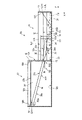
- FIG. 9 is a schematic cross-sectional view of the tank part TA along line BB in FIG.
- FIG. 10 is a schematic perspective view of the second flow path R2.
- FIG. 11 is a schematic cross-sectional view of the tank part TA along line DD in FIG.
- FIG. 9 is a cross section of the tank portion TA viewed from the Y direction.
- FIG. 11 is a cross section of the tank part TA viewed from the X direction.
- FIG. 10 illustrates part of the second flow path R2 and the tank part TA.
- the second flow path R2 is provided along the second side surface 12A and the sixth side surface 12B of the second side plate 12. As shown in FIG. The second flow path R2 is located on the connection portion J3 side of the first tank T1.
- the second flow path R2 has a first portion R21 provided on the first tank T1 side and a second portion R22 provided on the second tank T2 side.
- the first portion R21 and the second portion R22 are connected via an opening OP (see FIG. 10) of the partition plate 15 shown in FIG.
- the opening OP is provided at the end of the partition plate 15 on the second side plate 12 side.
- the second flow path R2 has an end portion R2a located on the side of the fourth side plate 14 in the X direction, an end portion R2b located on the side of the third side plate 13, and a connection portion R2c connected to the opening OP.
- the X-direction length of the second portion R22 is longer than the X-direction length of the first portion R21.
- the X-direction length of the second portion R22 may be shorter than the X-direction length of the first portion R21.
- the first portion R21 is inclined in the direction opposite to the X direction so as to approach the bottom surface 10A from the connection portion R2c toward the end portion R2b.
- the inclination from the connection portion R2c to the end portion R2b is constant.
- the length between the connecting portion R2c and the bottom surface 10A in the Z direction is longer than the length between the end portion R2b and the bottom surface 10A.
- the end portion R2b is positioned closer to the bottom surface 10A in the Z direction than the connection portion R2c.
- the liquid flowing through the first portion R21 flows from the connecting portion R2c toward the end portion R2b.
- the connecting portion R2c side corresponds to the upstream side
- the end portion R2b side corresponds to the downstream side.
- the second portion R22 is inclined in the direction opposite to the X direction so as to approach the bottom surface 10B from the end portion R2a toward the connecting portion R2c.
- the inclination from the end portion R2a to the connecting portion R2c is constant. From another point of view, the length between the end R2a in the Z direction and the bottom surface 10B is longer than the length between the connecting portion R2c and the bottom surface 10B.
- the connection portion R2c is positioned closer to the bottom surface 10B in the Z direction than the end portion R2a.
- the liquid flowing through the second portion R22 flows from the end portion R2a toward the connecting portion R2c.
- the end portion R2a side corresponds to the upstream side
- the connection portion R2c side corresponds to the downstream side.
- the end portion R2a side corresponds to the upstream side
- the end portion R2b side corresponds to the downstream side.
- the liquid flowing through the second flow path R2 flows from the end R2a toward the end R2b through the connecting portion R2c (opening OP).
- the arrow FR2 indicates the flow direction of the liquid flowing through the second flow path R2.
- the liquid flowing through the second flow path R2 flows from the eighth side surface 14B toward the third side surface 13A.
- the flow direction of the liquid flowing through the second flow path R2 is opposite to the flow direction of the liquid flowing through the first flow path R1.
- the end R2a is connected to the eighth side surface 14B, and no gap is formed between the end R2a and the eighth side surface 14B.
- the end R2b is positioned near the center of the second side surface 12A in the X direction.
- the angle ⁇ 4 formed between the surface parallel to the bottom surfaces 10A and 10B and the second portion R22 is larger than the angle ⁇ 3 formed between the surface parallel to the bottom surfaces 10A and 10B and the first portion R21 ( ⁇ 4> ⁇ 3).
- the first portion R21 is inclined at the same inclination as the first flow path R1 described using FIG. 6, for example.
- the first portion R21 of the second flow path R2 has a bottom plate 34 connected to the second side surface 12A and side plates 35 connected to the bottom plate 34.
- a second portion R22 of the second flow path R2 has a bottom plate 36 connected to the sixth side surface 12B and a side plate 37 connected to the bottom plate 36. As shown in FIG.
- the bottom plates 34, 36 are rectangular. In the illustrated example, the bottom plate 34 and the bottom plate 36 have the same length in the Y direction (width direction). In the illustrated example, the Y-direction (width direction) length of the bottom plate 31 of the first flow path R1 is shorter than the Y-direction (width direction) length of the bottom plates 34 and 36 of the second flow path R2. Depending on the throughput of the filtration device 100, the Y-direction (width direction) length of the bottom plate 31 of the first flow path R1 is greater than the Y-direction (width direction) length of the bottom plates 34 and 36 of the second flow path R2. may be longer.
- the side plates 35 and 37 are provided parallel to the second side plate 12 .
- the bottom plates 34 and 36 and the side plates 35 and 37 are made of, for example, a metal material like the bottom plate 10 and the first side plate 11 forming the tank part TA.
- the first portion R21 and the second portion R22 of the second flow path R2 may be formed from a plurality of plate members, or may be formed by bending one plate member.
- the bottom plate 34 is inclined in the Y direction so as to approach the bottom surface 10A from the side 35a connected to the side plate 35 toward the side 34a connected to the second side surface 12A. From another point of view, in the Y direction, the length between the side 35a in the Z direction and the bottom surface 10A is longer than the length between the side 34a and the bottom surface 10A.
- an angle ⁇ 5 between a plane parallel to the bottom surface 10A and the bottom plate 34 is, for example, 15 degrees or more and 60 degrees or less (15° ⁇ 5 ⁇ 60°), preferably It is 25 degrees or more and 45 degrees or less (25° ⁇ 5 ⁇ 45°).
- the bottom plate 34 can be provided so that the angle ⁇ 5 is 30 degrees.
- the angle ⁇ 5 may be equal to the angle ⁇ 2 formed by the bottom plate 31 and the plane parallel to the bottom surface 10A in the first flow path R1 described with reference to FIG. 8, for example.
- the bottom plate 36 is inclined in the Y direction so as to approach the bottom surface 10B from the side 37a connected to the side plate 37 toward the side 36a connected to the sixth side surface 12B. From another point of view, in the Y direction, the length between the side 37a in the Z direction and the bottom surface 10B is longer than the length between the side 36a and the bottom surface 10B. For example, the angle formed by the bottom plate 36 and a plane parallel to the bottom surface 10B in the Y direction is equal to the angle ⁇ 5.
- the amount of liquid flowing through the second flow path R2 is reduced compared to the case where the bottom plates 34 and 36 are not tilted in the Y direction, similarly to the first flow path R1. flow speed increases.
- the increased flow velocity of the liquid flowing through the second flow path R2 can be utilized to increase the flow velocity of the liquid flowing through the first tank T1.
- the bottom plate 34 is inclined as described above, it is difficult for suspended matter to stay between the liquid surface of the liquid stored in the first tank T1 and the bottom plate 34, as in the case of the first flow path R1.
- the side 35a of the side plate 35 and the side 35b located on the opposite side are parallel to the X direction.
- a side 37b of the side plate 37 located opposite to the side 37a is parallel to the X direction.
- liquid levels of the liquid stored in the first tank T1 during operation of the filtering device 100 are indicated by liquid levels L1L and L1H, respectively. This is the same as the liquid levels L1L and L1H shown in FIG. Also, the liquid level of the liquid stored in the second tank T2 is indicated by a liquid level L2H.
- the liquid surface L2H roughly overlaps with the side 37b. Comparing the first tank T1 and the second tank T2, the length of the liquid surface L2H and the bottom surface 10B is longer than the length of the liquid surface L1H and the bottom surface 10A.
- the length D5 between the Z-direction end R2b and the bottom surface 10A is shorter than the length D2 between the liquid surface L1L and the bottom surface 10A (D5 ⁇ D2).
- the end R2b is submerged in the liquid when the filtering device 100 is in operation. Therefore, a gap is less likely to be formed between the end R2b and the liquid surface.
- the side 35b of the side plate 35 is farther from the bottom surface 10A than the liquid surface L1H in the Z direction.
- the length D6 between the side 35b in the Z direction and the bottom surface 10A is longer than the length D4 between the liquid surface L1H and the bottom surface 10A (D6>D4). It is difficult for the liquid stored in the first tank T1 to flow over the side plate 35 and into the first portion R21 when the filtering device 100 is in operation. Therefore, the flow of the liquid flowing through the first portion R21 is less likely to be blocked by the liquid stored in the first tank T1, and the speed of the liquid flowing through the first portion R21 is less likely to decrease.
- the length of the side 37b and the bottom surface 10B in the Z direction is approximately equal to the length of the liquid surface L2H and the bottom surface 10B.
- the flow rate flowing into the second tank T2 (the processing amount of the second processing device 2) is 150 L/min
- the flow rate flowing out to the machine tool by the second pump P2 (first processing When the throughput of the apparatus 1) is 60 L/min
- the flow rate flowing from the second tank T2 to the first tank T1 changes while the machine tool is operating and stopped.
- the flow paths R1 and R2 flow at a predetermined flow rate.
- the flowing liquid can be smoothly made to flow into the first tank T1. Therefore, the flow of the liquid flowing through the flow paths R1 and R2 can be used to generate eddy currents in the first tank T1, increase the flow velocity of the liquid flowing through the first tank T1, and the like.
- the ends R1b and R2b are immersed in the liquid, it is possible to suppress bubbling on the liquid surface when the liquid flows from the flow paths R1 and R2 into the first tank T1.
- the liquid flowing in from the first flow path R1 passes through the first side surface 11A, the inclined surface S2, the fourth side surface 15A, the inclined surface S3, the second side surface 12A, the inclined surface S4, the third side surface 13A, and the inclined surface 13A. It flows in the first tank T1 along each surface in order of the surface S1, the first side surface 11A, and the inclined surface S2.
- the liquid flowing in from the second flow path R2 also flows in the first tank T1 along each surface in the same order from the second side surface 12A.
- a vortex is generated by the liquid flowing in from each flow path R1, R2 flowing in the first tank T1 along each surface as described above.
- the flow velocity of the liquid flowing through the first tank T1 is lower than that in the case where the inclined surfaces S1 to S4 are not provided. can be made significantly faster.
- FIG. 12 is a schematic perspective view of the filtering device 100 on the side of the first tank T1.
- the first tank T1 side of the filtering device 100 is shown, and other parts are omitted.
- the first pump P1 is provided in the central portion CE of the first tank T1 by a support SA1 provided on the upper side of the first tank T1.
- the support SA1 is made of steel or plate, for example.
- a support SA2 extends from the support SA1 toward the bottom surface 10A, and a plate material BP is attached to the tip of the support SA2.
- the supports SA1 and SA2 are made of, for example, a metal material, like the bottom plate 10, the first side plate 11, and the like.
- the plate material BP is provided between the first pump P1 and the first side surface 11A of the first side plate 11.
- the plate member BP is positioned closer to the first pump P1 than the first side surface 11A.
- the position where the plate member BP is provided is not limited to the illustrated example, and may be between the first pump P1 and the side surfaces 12A, 13A, 15A and the inclined surfaces S1 to S4.
- the position where the plate member BP is provided may be between the first pump P1 and each of the connecting portions J1 to J4.
- FIG. 13 is an enlarged view showing the vicinity of the plate material BP in FIG. 14 is a schematic plan view of the plate material BP in FIG. 13.
- FIG. FIG. 14 shows an arrow F, which is the flow direction of the vortex.
- the plate material BP has a rectangular shape.
- the plate material BP has a surface B1 and a surface B2 located on the opposite side of the surface B1.
- the plate material BP is provided in the first tank T1 so that the surface B1 intersects the flow direction of the eddy current.
- the plate material BP is provided parallel to the Z direction.
- Support SA2 is connected with surface B2.
- the support SA2 is, for example, a rod-shaped member, and is a round rod in the illustrated example.
- the plate material BP is made of, for example, a metal material, like the bottom plate 10 and the first side plate 11 forming the tank part TA.
- the plate material BP is bent at the end Ba on the side of the first side surface 11A (the side away from the first pump P1).
- the end Ba is bent into an R shape.
- the plate material BP has a portion with a curved surface located on the side of the first side surface 11A and a portion with a flat surface.
- the end Ba corresponds to, for example, a portion having a curved surface.
- the plate material BP is provided with the end Ba directed in the direction opposite to the flow direction (arrow F) of the eddy current.
- a gap SP1 with the bottom surface 10A, a gap SP2 with the first pump P1, and a gap SP3 with the first side surface 11A are formed around the plate material BP.
- the plate material BP is not in contact with the bottom surface 10A, the first pump P1, and the first side surface 11A.
- the liquid stored in the first tank T1 can flow around the plate material BP.
- liquid level of the liquid stored in the first tank T1 during operation of the filtering device 100 is indicated by a liquid level L1L. This is the same as the liquid level L1L illustrated in FIGS. Further, in FIG. 13, a liquid level L1LL indicates a liquid level necessary for the first pump P1 not to suck in air during operation.
- the length D7 between the side B1a of the plate member BP on the side of the bottom surface 10A and the bottom surface 10A is shorter than the length D2 between the liquid surface L1L and the bottom surface 10A (D7 ⁇ D2).
- a length D7 between the side B1a and the bottom surface 10A is shorter than a length D8 between the liquid surface L1LL and the bottom surface 10A (D7 ⁇ D8).
- the length D8 between the liquid surface L1LL and the bottom surface 10A is shorter than the length D2 between the liquid surface L1L and the bottom surface 10A (D8 ⁇ D2).
- the surface of the liquid stored in the first tank T1 may change like a mortar when a whirlpool occurs.
- the liquid level in the first tank T1 decreases from the side surfaces 11A to 13A and 15A toward the central portion CE (first pump P1 side). If the liquid level on the side of the first pump P1 drops extremely, it may cause the first pump P1 to suck in air (air entrapment) during operation.
- the plate member BP it is possible to suppress the change in the liquid surface in the first tank T1 as described above.
- the gaps SP1 to SP3 are formed around the plate material BP, the flow of the liquid flowing on the side of the bottom surface 10A of the first tank T1 is less likely to be obstructed. Therefore, foreign matter in the first tank T1 is less likely to stay around the plate material BP. Even when the plate material BP is provided, the centripetal force acting on the foreign matter in the eddy current is less likely to be hindered.
- FIG. 15 is a schematic plan view showing another example of the plate material BP provided in the first tank T1.
- two plate members BP are provided in the first tank T1.
- two plates BP may be provided as illustrated.
- the two plate members BP are preferably provided at 180-degree symmetrical positions with respect to the first pump P1 (central portion of the vortex).
- the edge Ba of the plate material BP faces the direction opposite to the flow direction (arrow F) of the eddy current.
- foreign matter contained in the liquid discharged from the machine tool can be efficiently treated. That is, since a uniform and fast flow can be formed in the liquid stored in the first tank T1, it is difficult for foreign substances to stay or accumulate in the first tank T1, and the generated vortex flow can cause a change in the first tank T1. Most of the foreign matter can be collected in the central part CE.
- the first tank T1 is square, it is possible not only to increase the capacity of the first tank T1, but also to efficiently treat liquid containing foreign matter, as compared with a cylindrical tank. .
- the configuration of the filtering device 100 according to this embodiment is merely an example.
- the filtration device 100 further includes other components such as an oil recovery device for recovering oil from the surface of the liquid stored in the second tank T2, and a temperature controller (cooler) for adjusting the liquid temperature.
- an oil recovery device for recovering oil from the surface of the liquid stored in the second tank T2
- a temperature controller for adjusting the liquid temperature.
- FIG. 16 is a schematic side view showing another example of the tank part TA.
- FIG. 17 is a schematic plan view showing another example of the tank part TA.
- the first tank T1 and the second tank T2 may be rectangular in plan view.
- the length of the short side is 1, the length of the long side is 1 or more and 1.3 or less.
- the ratio of the length of the short side to the length of the long side in the first tank T1 is, for example, 1:1.3.
- Each of the first tank T1 and the second tank T2 may be rectangular, or only one of them may be rectangular. Even though the first tank T1 is rectangular, the first pump P1 is located in the central part CE of the first tank T1. As illustrated, the X-direction length X1 of the first tank T1 may be longer than the X-direction length X2 of the second tank T2.
- FIG. 18 is a schematic plan view showing another example of the second flow path R2.
- a gap may be formed between the end portion R2a and the eighth side surface 14B in the second portion R22 of the second flow path R2.
- a side plate 38 parallel to the fourth side plate 14 may be further provided at the end portion R2a.
- the end portion R2a is positioned closer to the fourth side plate 14 than the partition plate 15 in the X direction.
- FIG. 19 is a plan view showing another example of the position of the first processing device 1 in the first tank T1.
- the first processing apparatus 1 is positioned on the connection portion J4 side of the first tank T1.
- the first processing device 1 overlaps the plate material 24 in the Z direction.
- the first flow path R1 is provided along the third side surface 13A of the third side plate 13 in the first tank T1.
- An end portion R1a of the first flow path R1 is located on the second side plate 12 side, and an end portion R1b is located on the first side plate 11 side.
- the end portion R1a is connected to the second side surface 12A, and no gap is formed between the end portion R1a and the second side surface 12A.
- the liquid flowing through the first flow path R1 flows from the second side surface 12A side toward the first side surface 11A side.
- FIG. 20 is a plan view showing still another example of the position of the first processing device 1 in the first tank T1.
- the first processing apparatus 1 is positioned on the connection portion J2 side of the first tank T1.
- the first processing device 1 overlaps the plate material 22 in the Z direction.
- the first flow path R1 is provided along the fourth side surface 15A of the partition plate 15 in the first tank T1.
- An end portion R1a of the first flow path R1 is located on the first side plate 11 side, and an end portion R1b is located on the second side plate 12 side.
- the end portion R1a is connected to the first side surface 11A, and no gap is formed between the end portion R1a and the first side surface 11A.
- the liquid flowing through the first flow path R1 flows from the first side surface 11A side toward the second side surface 12A side.
- the flow direction of the liquid flowing through the first flow path R1 intersects the flow direction of the liquid flowing through the second flow path R2.
- eddy currents are generated in the first tank T1 by the liquid flowing from the first flow path R1 and the second flow path R2.
Landscapes
- Chemical & Material Sciences (AREA)
- Chemical Kinetics & Catalysis (AREA)
- Engineering & Computer Science (AREA)
- Mechanical Engineering (AREA)
- Auxiliary Devices For Machine Tools (AREA)
- Frying-Pans Or Fryers (AREA)
- Centrifugal Separators (AREA)
- Fluid-Pressure Circuits (AREA)
- Control Of Throttle Valves Provided In The Intake System Or In The Exhaust System (AREA)
Abstract
工作機械から排出された液体に含まれる異物をより効率的に処理することができる濾過装置を提供する。 本発明の一態様に係る濾過装置は、異物を含む液体が流入する第1タンクを有するタンク部と、前記第1タンクの中央部に設けられ、前記第1タンクに貯留された前記液体を排出するポンプと、を備えている。前記第1タンクは、底面と、前記底面に接続された4つの側面と、前記底面と前記4つの側面のうち2つの側面とがそれぞれ接続された4つの角と、前記4つの角をそれぞれ覆う4つの傾斜面と、を有している。前記4つの傾斜面は、前記2つの側面が接続された接続部から前記中央部に向かうにしたがい前記底面に近づくように傾き、前記第1タンクに流入する前記液体により、前記第1タンク内に渦流を発生させ、前記異物を前記第1タンクの前記中央部に集めて前記ポンプにより排出する。
Description
本発明は、濾過装置に関する。
工作機械により金属材料等を研削、切削等する際、加工精度の向上や、使用する工具の寿命の延命および切り屑や金属粉等の排出を促進することを目的として研削液、切削液、クーラント等と呼ばれる各種の液体が使用されている。これらの液体は、機械加工により生じた切り屑や金属粉等の異物が含まれた状態で工作機械から排出される。
工作機械から排出された液体は、切り屑等の異物を分離して除去した後、再び工作機械に戻して利用される。そのため、工作機械から排出された液体を回収し、異物を分離して除去するために種々の装置が知られている。
例えば、特許文献1には、濾過槽内に異物を含む液体が流入されると、濾過槽の角部に設けられた湾曲板に沿って液体が流動し、濾過槽の内部に渦流を発生させ、この渦流により異物を濾過槽の中央部に集め、集まった異物をポンプにより吸引して排出するための濾過装置が開示されている。当該濾過装置であれば、濾過槽に渦流を発生させるための装置を設置したり、濾過槽自体を円筒形状に形成したりすることなく、渦流を発生することができるという利点がある。
上記特許文献1に開示された濾過装置を踏まえても、工作機械から排出された液体に含まれる異物の分離や除去に関しては未だに種々の改善の余地がある。液体から異物を分離したり除去したりするために、例えば、濾過槽(タンク)内において異物が滞留しにくいこと等が要望されている。そこで、本発明は、工作機械から排出された液体に含まれる異物をより効率的に処理することができる濾過装置を提供することを目的の一つとする。
本発明の一態様に係る濾過装置は、異物を含む液体が流入する第1タンクを有するタンク部と、前記第1タンクの中央部に設けられ、前記第1タンクに貯留された前記液体を排出するポンプと、を備えている。前記第1タンクは、底面と、前記底面に接続された4つの側面と、前記底面と前記4つの側面のうち2つの側面とがそれぞれ接続された4つの角と、前記4つの角をそれぞれ覆う4つの傾斜面と、を有している。前記4つの傾斜面は、前記2つの側面が接続された接続部から前記中央部に向かうにしたがい前記底面に近づくように傾き、前記第1タンクに流入する前記液体により、前記第1タンク内に渦流を発生させ、前記異物を前記第1タンクの前記中央部に集めて前記ポンプにより排出する。
本発明の一態様に係る濾過装置は、異物を含む液体を処理する第1処理装置と、前記第1処理装置により処理された前記液体が流入する第1タンクを有するタンク部と、前記第1タンクの中央部に設けられ、前記第1タンクに貯留された前記液体を排出するポンプと、を備えている。前記第1タンクは、底面と、前記底面に接続された複数の側面と、複数の前記側面の1つである第1側面に沿って設けられ、前記第1処理装置で処理された前記液体が流れる第1流路と、を有している。
前記第1流路は、前記第1処理装置の出口側に位置する上流から前記底面側に位置する下流に向けて傾き、かつ前記第1側面に向かうにしたがい前記底面に近づくように傾く底板を有している。前記第1タンクに流入する前記液体により、前記第1タンク内に渦流を発生させ、前記異物を前記第1タンクの前記中央部に集めて前記ポンプにより排出する。
本発明によれば、工作機械から排出された液体に含まれる異物をより効率的に処理することができる濾過装置を提供することができる。
濾過装置の一実施形態につき、図面を参照しながら説明する。
本実施形態においては、例えば研摩機のような工作機械から排出される研削液から異物を処理する濾過装置を例示する。異物には、研削によって生じた金属粉、砥粒等が含まれる。
本実施形態においては、例えば研摩機のような工作機械から排出される研削液から異物を処理する濾過装置を例示する。異物には、研削によって生じた金属粉、砥粒等が含まれる。
図1は、本実施形態に係る濾過装置100の概略的な側面図である。図2は、本実施形態に係る濾過装置100の概略的な平面図である。以下の説明においては、図1および図2に示すようにX方向、Y方向およびZ方向を定義する。X方向およびY方向は、いずれも濾過装置100の設置面と平行な水平方向に相当し、互いに直交している。Z方向は、鉛直方向に相当し、X方向およびY方向と直交している。Z方向の矢印が示す方向を上方と呼ぶことがある。また、X方向およびY方向で規定されるX-Y平面を見ることを平面視と呼ぶことがある。
濾過装置100は、液体を貯留するタンク部TAと、異物を含む液体を処理する第1処理装置1および第2処理装置2と、タンク部TAに貯留された液体を排出する第1ポンプP1および第2ポンプP2とを備えている。ここで、「処理する」とは、例えば工作機械から排出された液体に含まれる異物を当該液体から分離したり、除去したりすることをいう。
タンク部TAは、平面視においてX方向の長さがY方向の長さよりも長い長方形状である。タンク部TAは、第1タンクT1と第2タンクT2とを有している。タンク部TAには、第1処理装置1で処理された液体が流れる第1流路R1と、第2タンクT2に貯留された液体が流れる第2流路R2とを有している。第1流路R1および第2流路R2は、平面視において第1タンクT1の対角に位置している。
第1タンクT1には、第1流路R1および第2流路R2から液体が流入することにより渦流が発生する。液体とともに第1タンクT1に流入した異物には、発生した渦流により渦流の中央部に向かう力(向心力)が働く。そのため、異物は、渦流により第1タンク内を旋回しながら第1タンクT1の中央部CEに集められる。
渦流の中央部は、第1タンクT1の中央部CEと重なっている。第1タンクT1の中央部CEは、例えば、平面視において第1タンクT1の対角線の交点と重なる。図2において、渦流の流れ方向を矢印Fで示す。さらに、第1タンクT1には、第1ポンプP1の近傍に渦流の流れ方向と交差する面B1を有する板材BPが設けられている。
図示した例において、第1処理装置1および第2処理装置2は、第1タンクT1の上方に設けられている。第1処理装置1は、工作機械から排出された液体を第1タンクT1に流入する前に処理する。第1処理装置1は、例えばマグネット式のセパレータである。工作機械から排出された液体に磁性体が含まれる場合、第1処理装置1にて液体から磁性体が処理される。
第1処理装置1は、第1タンクT1に向けて開口する出口1aを有している。第1処理装置1で処理された液体は、出口1aから排出される。第1処理装置1での液体の処理量は、例えば毎分80L~360Lである。第1処理装置1から排出された液体には、第1処理装置1では処理できなかった異物が含まれている。
第2処理装置2は、第1タンクT1から排出される液体を第2タンクT2に流入する前に処理する。第2処理装置2は、例えば液体に含まれる異物を遠心力により除去するサイクロン式の異物分離装置である。第2処理装置2では、第1処理装置1では処理できなかった異物が液体から処理される。第2処理装置2で処理された異物は、タンク部TAとは異なる回収タンクへ排出される。第2処理装置2での液体の処理量は、例えば毎分100L~300Lである。第2処理装置2は、入口2aと、出口2bとを有している。
第1ポンプP1は、第1タンクT1の中央部CEに設けられている。第2ポンプP2は、第2タンクT2における第2流路R2の近傍に設けられている。第1ポンプP1および第2ポンプP2の各々は、後述の底面10A,10B側に位置する吸込口P1a,P2aと、吐出口P1b,P2bとを有している。第1タンクT1の中央部CEに集められた異物は、液体とともに第1ポンプP1の吸込口P1aから吸い込まれ、吐出口P1bより排出される。
第1ポンプP1の吐出口P1bは、ホースH1により第2処理装置2の入口2aと接続されている。第2処理装置2の出口2bは、ホースH2により第2タンクT2に設けられた導入管TPと接続されている。第1処理装置1、第2処理装置2、第1ポンプP1および第2ポンプP2は、サポート等によりタンクT1,T2にそれぞれ設けられている。
次に濾過装置100における液体の流れを説明する。まず、図示しない工作機械から排出された液体は、第1タンクT1に流入する前に第1処理装置1で処理される。第1処理装置1で処理された液体は、出口1aから排出される。第1タンクT1の第1流路R1は、Z方向において出口1aと重なる位置に設けられている。出口1aから排出された液体は、第1流路R1を通り第1タンクT1に流入する。
第1処理装置1で処理できなかった異物は、液体とともに第1タンクT1に流入する。異物が第1タンクT1に流入すると、第1タンクT1内の渦流により旋回しながら第1タンクT1の中央部CEに集められる。そして、第1タンクT1に貯留された液体は、中央部CEに集められた異物とともに第1ポンプP1の吸込口P1aから吸い込まれる。
第1ポンプP1に吸い込まれた液体は、吐出口P1bからホースH1を介して入口2aから第2処理装置2に流入し、処理される。第2処理装置2で処理された液体は、出口2bからホースH2を介して導入管TPから第2タンクT2に流入する。第2処理装置2で処理された液体には、異物がほとんど含まれていない。
第2タンクT2に貯留された液体は、第2ポンプP2の吸込口P2aから吸い込まれ、吐出口P2bに接続された図示しない配管類を介して再び工作機械に送られる。また、第2タンクT2において、第2タンクT2に貯留された液体の液面が規定の高さを超えると、第2タンクT2に貯留された液体が第2流路R2を介して第2タンクT2から第1タンクT1へ流入する。
次にタンク部TAについて、説明する。図3は、濾過装置100が備えるタンク部TAの概略的な斜視図である。図4は、濾過装置100が備えるタンク部TAの概略的な平面図である。また、図3以降においては、濾過装置100を構成する第1ポンプP1等の要素を一部省略している。
タンク部TAは、底板10と、Y方向に並ぶ第1側板11および第2側板12と、X方向に並ぶ第3側板13および第4側板14とにより形成されている。第1側板11および第2側板12は、X方向およびZ方向で規定されるX-Z平面に平行である。第3側板13および第4側板14は、Y方向およびZ方向で規定されるY-Z平面に平行である。タンク部TAは、第3側板13と第4側板14の間に位置し、第3側板13および第4側板14と平行な仕切り板15をさらに有している。仕切り板15は、タンク部TAを第3側板13側に位置する第1タンクT1と第4側板14側に位置する第2タンクT2とに隔てている。
第1側板11および第2側板12のX方向の長さは等しい。第3側板13、第4側板14および仕切り板15のY方向の長さは等しい。第3側板13のZ方向の長さは、第4側板14のZ方向の長さよりも短い。また、第4側板14のZ方向の長さは、仕切り板15のZ方向の長さと等しい。
第1側板11および第2側板12において、第3側板13と接続される辺の長さは、第3側板13のZ方向の長さと等しく、第4側板14と接続される辺の長さは、第4側板14のZ方向の長さと等しい。第1側板11および第2側板12において、仕切り板15と接続される部分のZ方向の長さは、第4側板14と接続される辺の長さと等しい。そのため、第2タンクT2のZ方向の長さは、第1タンクT1のZ方向の長さよりも長い。第2タンクT2に貯留される液体の液面は、第1タンクT1に貯留される液体の液面よりも高くすることができる。
第1タンクT1と第2タンクT2は上方が開口した直方体形状であり、X方向に沿って第1タンクT1、第2タンクT2の順に並んでいる。図示した例において、第1タンクT1は、平面視においてX方向およびY方向の長さが等しい正方形状である。第1タンクT1と同様に、第2タンクT2はX方向およびY方向の長さが等しい正方形状であってもよいし、長方形状であってもよい。
タンク部TAの大きさは、第1処理装置1や第2処理装置2の処理量等により適宜変更される。例えば、第1タンクT1のX方向の長さは、500mm~2000mmである。例えば、第1タンクT1のY方向の長さは、500mm~2000mmである。例えば、第1タンクT1のZ方向の長さは、例えば、200mm~500mmである。
タンク部TAは、板材を折り曲げること等により形成されてもよい。また、第1タンクT1および第2タンクT2は、それぞれ分離したタンクとして形成されてもよい。底板10、各側板11~14および仕切り板15は、例えば金属材料で形成される。
第1タンクT1は、底板10が有する底面10Aと、第1側板11が有する第1側面11Aと、第2側板12が有する第2側面12Aと、第3側板13が有する第3側面13Aと、仕切り板15が第1タンクT1側に有する第4側面15Aとを有している。側面11A~13A,15Aの4つは、底面10Aに接続されている。第1側面11Aは、Y方向において第2側面12Aと対向している。第3側面13Aは、X方向において第4側面15Aと対向している。
第1タンクT1は、第1側面11Aと第3側面13Aが接続された接続部J1と、底面10Aと接続部J1(第1側面11Aと第3側面13A)が接続された角C1を有している。同様に、第1タンクT1は、第1側面11Aと第4側面15Aが接続された接続部J2と、底面10Aと接続部J2(第1側面11Aと第4側面15A)が接続された角C2を有している。
第1タンクT1は、第2側面12Aと第4側面15Aが接続された接続部J3と、底面10Aと接続部J3(第2側面12Aと第4側面15A)が接続された角C3を有している。第1タンクT1は、第2側面12Aと第3側面13Aが接続された接続部J4と、底面10Aと接続部J4(第2側面12Aと第3側面13A)が接続された角C4を有している。接続部J1~J4は各側面によりなす角度がおよそ90度で接続されているが、各接続部J1~J4は丸みを有してもよい。
さらに、第1タンクT1には、角C1~C4を覆う4つの傾斜面S1~S4がそれぞれ設けられている。本実施形態においては、各傾斜面S1~S4は板材21~24により形成されている。板材21~24の形状は、例えば三角形状である。また、板材21,23のように第1流路R1および第2流路R2と接触する場合等には、三角形状の板材の一部が加工されてもよい。
板材21~24は、一例として湾曲した面を有さない平板であることが好ましい。4枚の板材21~24を設けることで、角C1~C4の各々を第1タンクT1の中央部CE側から覆うことができる。板材21~24は、タンク部TAを形成する底板10や第1側板11等と同様に、例えば金属材料で形成される。
図示した例において、傾斜面S1は底面10Aと第1側面11Aと第3側面13Aとに接続されている。傾斜面S2は、底面10Aと第1側面11Aと第4側面15Aとに接続されている。傾斜面S3は、底面10Aと第2側面12Aと第4側面15Aとに接続されている。傾斜面S4は、底面10Aと第2側面12Aと第3側面13Aとに接続されている。そのため、角C1~C4と傾斜面S1~S4の間には、液体は流れない。
図5は、図4におけるA-A線に沿うタンク部TAの概略的な断面図である。ここでは、図5を用いて角C4を覆う傾斜面S4について説明する。上述の通り角C4には、底面10Aと接続部J4が接続されている。板材24の傾斜面S4は、角C4を第1タンクT1の中央部CE側から覆うように第1タンクT1に設けられている。
例えば、板材24の第2側面12Aと接続された辺の長さは、第3側面13Aと接続された辺の長さと等しい。また、板材24の第2側面12Aと接続された辺の長さは、底面10Aと接続された辺の長さよりも短くてもよいし、長くてもよいし、または等しくてもよい。
傾斜面S4は、接続部J4から図4に図示する第1タンクT1の中央部CEに向かうにしたがい底面10Aに近づくように傾いている。底面10Aと板材24とがなす角度θ1は、例えば60度以下であることが好ましい。角度θ1は、濾過装置100の処理量や第1タンクT1の容量等に応じて適宜変更される。
例えば、第1タンクT1の大きさに応じて角度θ1が45度,50度,55度となるように板材24を設けることができる。また、板材24の底面10Aと反対側に位置する頂点は、例えばZ方向において第1タンクT1に貯留される液体の液面よりも底面10Aから離れている。板材24の底面10Aと反対側に位置する頂点は、Z方向において第1タンクT1に貯留される液体の液面よりも底面10Aに近くてもよい。
角C4を覆う傾斜面S4について説明したが、他の傾斜面S1~S3においても同様である。つまり、板材21は、傾斜面S1が角C1を覆うように第1タンクT1に設けられている。板材22は、傾斜面S2が角C2を覆うように第1タンクT1に設けられている。板材23は、傾斜面S3が角C3を覆うように第1タンクT1に設けられている。例えば、底面10Aと板材21~23の各々がなす角度が角度θ1と等しくなるように、板材21~23は第1タンクT1に設けられている。
第1タンクT1の角C1~C4が傾斜面S1~S4によりそれぞれ覆われることで、第1タンクT1を流れる液体には流速が遅い部分が生じにくく、液体がほぼ均一の流速で第1タンクT1内を流れることができる。第1タンクT1に傾斜面S1~S4を設けることで、第1タンクT1内の液体の回転効率を向上させることができる。
そのため、発生した渦流により第1タンクT1の全体を液体が流れやすくなり、第1タンクT1には異物の滞留や堆積が生じにくい。また、液面においても、泡や異物等の浮遊物の滞留が発生しにくい。
第2タンクT2は、底板10が有する底面10Bと、第1側板11が有する第5側面11Bと、第2側板12が有する第6側面12Bと、仕切り板15が第2タンクT2側(第4側面15Aと反対側)に有する第7側面15Bと、第4側板14が有する第8側面14Bとを有している。側面11B,12B,14B,15Bの4つは、底面10Bに接続されている。第5側面11Bは、Y方向において第6側面12Bと対向している。第7側面15Bは、X方向において第8側面14Bと対向している。
次に、第1流路R1について説明する。図6は、図4におけるB-B線に沿うタンク部TAの概略的な断面図である。図7は、第1流路R1の概略的な斜視図である。図8は、図4におけるC-C線に沿うタンク部TAの概略的な断面図である。図6はY方向と反対方向から見たタンク部TAの断面である。図8はX方向と反対方向から見たタンク部TAの断面である。
図6に図示するように、第1流路R1は、第1タンクT1において第1側板11の第1側面11Aに沿って設けられている。第1流路R1は、第1タンクT1の接続部J1側に位置している。第1流路R1は、X方向において第3側板13側に位置する端部R1aと、仕切り板15側に位置する端部R1bを有している。端部R1a側の上方には、図1および図2に図示した第1処理装置1の出口1aが位置している。
第1流路R1は、X方向において端部R1aから端部R1bに向かうにしたがい底面10Aに近づくように傾いている。端部R1aから端部R1bへの傾きは、一定である。他の観点からは、Z方向の端部R1aと底面10Aとの長さは、端部R1bと底面10Aとの長さよりも長い。端部R1aよりも端部R1bの方が、Z方向において底面10A側に位置している。第1流路R1を流れる液体は、端部R1aから端部R1bに向けて流れる。
第1流路R1においては、端部R1a側が上流に相当し、端部R1b側が下流に相当する。図4において、第1流路R1を流れる液体の流れ方向を矢印FR1で示す。第1流路R1を流れる液体は、第3側面13A側から第4側面15A側に向けて流れる。
図示した例において、端部R1aは第3側面13Aに接続されており、端部R1aと第3側面13Aの間には、隙間が形成されていない。端部R1bは、X方向において第1側面11Aの中央付近に位置している。第1流路R1を第1側面11Aの中央部付近まで延ばすことで、第1流路R1を流れる液体の流れを第1タンクT1における渦流の発生や第1タンクT1を流れる液体の流速を速くすること等により生かすことができる。
第1流路R1は、第1側面11Aに接続された底板31と、底板31に接続された底板32と、底板32に接続された側板33とを有している。底板31の形状は、長方形状である。底板32の形状は、三角形状である。底板32のY方向(幅方向)の長さは、X方向に沿って短くなっている。第1流路R1は、底板31,32により扇形状に形成されている。つまり、第1流路R1のY方向(幅方向)において、端部R1a側の長さは、端部R1b側の長さよりも長い。側板33は、Z方向と平行に設けられている。
例えば、第1流路R1の端部R1a側の大きさは、第1処理装置1の出口1aの大きさよりも大きい。この場合、第1処理装置1の出口1aから排出される液体は端部R1a側から第1流路R1に流入しやすい。
さらに、端部R1aと第3側面13Aの間には隙間が形成されていないため、第1処理装置1の出口1aから排出される液体は、第1流路R1を介さずに直接第1タンクT1に流入しにくい。第1処理装置1で処理された液体が第1流路R1を介して第1タンクT1に流入させることで、第1タンクT1における渦流の発生や第1タンクT1を流れる液体の流速を速くすること等に生かすことができる。
底板31,32や側板33は、タンク部TAを形成する底板10や第1側板11等と同様に、例えば金属材料で形成される。第1流路R1は、複数の板材から形成されてもよいし、1枚の板材を折り曲げることで形成されてもよい。
図8に図示するように、底板31は、Y方向と反対方向において、底板32と接続された辺32aから第1側面11Aと接続された辺31aに向かうにしたがい底面10Aに近づくように傾いている。他の観点からは、Y方向において、Z方向の辺32aと底面10Aとの長さは、辺31aと底面10Aとの長さよりも長い。
図8に図示するように、Y方向において、底面10Aに平行な面と底板31とがなす角度θ2は、例えば15度以上60度以下であって(15°≦θ2≦60°)、好ましくは25度以上45度以下である(25°≦θ2≦45°)。例えば、角度θ2が30度となるように底板31を設けることができる。
底板31が上述のように傾いていることで、Y方向において底板31が傾いていない場合と比較して、第1流路R1を流れる液体の流速が速くなる。流速が速くなることで、液体に含まれる異物を第1流路R1から第1タンクT1へ流入させやすくなる。さらに、第1流路R1を流れる液体の流速が速くなることで、第1タンクT1を流れる液体の流速を速くすることができる。
また、底板31が上述のように傾いていることで、第1タンクT1に貯留された液体と底板31と接触する部分における液体の流れが阻害されにくい。つまり、液体が底板31の液面側の面に沿って第1側面11A側から中央部CE側に向けて流れる。そのため、液面に泡や異物等の浮遊物が存在していても液体の流れとともに底板31に沿って流れるため、浮遊物が第1タンクT1に貯留された液体の液面と底板31との間に滞留しにくい。
一方、底板32は、Y方向において傾いていない。他の観点からは、側板33と接続された辺33aと底面10Aとの長さは、辺32aと底面10Aとの長さと等しい。底板32は、底板31と同様に、辺33aから辺32aに向かうにしたがい底面10Aに近づくように傾いてもよい。図6に図示するように、側板33が有する辺33aと反対側に位置する辺33bは、X方向と平行である。
図6において、濾過装置100の運転時における第1タンクT1に貯留される液体の液面を液面L1Lおよび液面L1Hにてそれぞれ示す。例えば、液面L1Lは液面が最も低い位置であり、液面L1Hは液面が最も高い位置である。第1タンクT1に貯留される液体の液面は、濾過装置100の運転時に液面L1Hから液面L1Lの範囲で変化することがある。
Z方向の端部R1bと底面10Aとの長さD1は、液面L1Lと底面10Aとの長さD2よりも短い(D1<D2)。端部R1bの少なくとも一部は、濾過装置100の運転時に液体に浸かっている。そのため、端部R1bと液面との間には、隙間が形成されにくい。
側板33の辺33bは、Z方向において液面L1Hよりも底面10Aから離れている。Z方向の辺33bと底面10Aとの長さD3は、液面L1Hと底面10Aとの長さD4よりも長い(D3>D4)。濾過装置100の運転時に第1タンクT1に貯留された液体は、側板33を越えて第1流路R1に流入しにくい。そのため、第1タンクT1に貯留された液体により第1流路R1を流れる液体の流れは阻害されにくく、第1流路R1を流れる液体の速度は低下しにくい。
次に、第2流路R2について説明する。図9は、図4におけるB-B線に沿うタンク部TAの概略的な断面図である。図10は、第2流路R2の概略的な斜視図である。図11は、図4におけるD-D線に沿うタンク部TAの概略的な断面図である。図9はY方向から見たタンク部TAの断面である。図11はX方向から見たタンク部TAの断面である。図10については、第2流路R2とタンク部TAの一部を図示している。
図9に図示するように、第2流路R2は、第2側板12の第2側面12Aと第6側面12Bに沿って設けられている。第2流路R2は、第1タンクT1の接続部J3側に位置している。第2流路R2は、第1タンクT1側に設けられた第1部分R21と、第2タンクT2側に設けられた第2部分R22とを有している。第1部分R21と第2部分R22は、図10に図示する仕切り板15が有する開口OP(図10参照)を介して接続されている。開口OPは、仕切り板15における第2側板12側の端部に設けられている。
第2流路R2は、X方向において第4側板14側に位置する端部R2aと、第3側板13側に位置する端部R2bと、開口OPと接続された接続部R2cとを有している。図示した例において、第2部分R22のX方向の長さは、第1部分R21のX方向の長さよりも長い。第2部分R22のX方向の長さは、第1部分R21のX方向の長さよりも短くてもよい。
第1部分R21は、X方向と反対方向において、接続部R2cから端部R2bに向かうにしたがい底面10Aに近づくように傾いている。接続部R2cから端部R2bへの傾きは、一定である。他の観点からは、Z方向の接続部R2cと底面10Aとの長さは、端部R2bと底面10Aとの長さよりも長い。接続部R2cよりも端部R2bの方が、Z方向において底面10A側に位置している。第1部分R21を流れる液体は、接続部R2cから端部R2bに向けて流れる。第1部分R21においては、接続部R2c側が上流に相当し、端部R2b側が下流に相当する。
第2部分R22は、X方向と反対方向において、端部R2aから接続部R2cに向かうにしたがい底面10Bに近づくように傾いている。端部R2aから接続部R2cへの傾きは、一定である。他の観点からは、Z方向の端部R2aと底面10Bとの長さは、接続部R2cと底面10Bとの長さよりも長い。端部R2aよりも接続部R2cの方が、Z方向において底面10B側に位置している。第2部分R22を流れる液体は、端部R2aから接続部R2cに向けて流れる。第2部分R22においては、端部R2a側が上流に相当し、接続部R2c側が下流に相当する。
つまり、第2流路R2においては、端部R2a側が上流に相当し、端部R2b側が下流に相当する。第2流路R2を流れる液体は、端部R2aから接続部R2c(開口OP)を通過し端部R2bに向けて流れる。図4において、第2流路R2を流れる液体の流れ方向を矢印FR2で示す。第2流路R2を流れる液体は、第8側面14B側から第3側面13A側に向けて流れる。第2流路R2を流れる液体の流れ方向は、第1流路R1を流れる液体の流れ方向と逆方向である。
図示した例において、端部R2aは第8側面14Bに接続されており、端部R2aと第8側面14Bの間には、隙間が形成されていない。端部R2bは、X方向において第2側面12Aの中央付近に位置している。このように第2流路R2を第2側面12Aの中央部付近まで延ばすことで、第1流路R1と同様に、第2流路R2を流れる液体の流れを第1タンクT1における渦流の発生や第1タンクT1を流れる液体の流速を速くすること等により生かすことができる。
図9に図示した例において、底面10A,10Bに平行な面と第2部分R22とがなす角度θ4は、底面10A,10Bに平行な面と第1部分R21とがなす角度θ3よりも大きい(θ4>θ3)。第1部分R21は、例えば図6を用いて説明した第1流路R1と同じ傾きで傾いている。
第2流路R2の第1部分R21は、第2側面12Aに接続された底板34と、底板34に接続された側板35とを有している。第2流路R2の第2部分R22は、第6側面12Bに接続された底板36と、底板36に接続された側板37とを有している。
底板34,36は、長方形状である。図示した例において、底板34と底板36のY方向(幅方向)の長さは等しい。図示した例においては、第1流路R1の底板31のY方向(幅方向)の長さは、第2流路R2の底板34,36のY方向(幅方向)の長さよりも短い。濾過装置100の処理量に応じて、第1流路R1の底板31のY方向(幅方向)の長さは、第2流路R2の底板34,36のY方向(幅方向)の長さよりも長くてもよい。側板35,37は第2側板12と平行に設けられている。
底板34,36や側板35,37は、タンク部TAを形成する底板10や第1側板11等と同様に、例えば金属材料で形成される。第2流路R2の第1部分R21および第2部分R22は、複数の板材から形成されてもよいし、1枚の板材を折り曲げることで形成されてもよい。
図11に図示するように、底板34は、Y方向において、側板35と接続された辺35aから第2側面12Aと接続された辺34aに向かうにしたがい底面10Aに近づくように傾いている。他の観点からは、Y方向において、Z方向の辺35aと底面10Aとの長さは、辺34aと底面10Aとの長さよりも長い。
図11に図示するように、Y方向において、底面10Aに平行な面と底板34とがなす角度θ5は、例えば15度以上60度以下であって(15°≦θ5≦60°)、好ましくは25度以上45度以下である(25°≦θ5≦45°)。例えば、角度θ5が30度となるように底板34を設けることができる。また、角度θ5は、例えば図8を用いて説明した第1流路R1における、底面10Aに平行な面と底板31とがなす角度θ2と等しくてもよい。
底板36は、Y方向において、側板37と接続された辺37aから第6側面12Bと接続された辺36aに向かうにしたがい底面10Bに近づくように傾いている。他の観点からは、Y方向において、Z方向の辺37aと底面10Bとの長さは、辺36aと底面10Bとの長さよりも長い。例えば、Y方向において底面10Bに平行な面と底板36とがなす角度は、角度θ5と等しい。
底板34,36が上述のように傾いていることで、第1流路R1と同様に、Y方向において底板34,36が傾いていない場合と比較して、第2流路R2を流れる液体の流速が速くなる。第2流路R2を流れる液体の流速が速くなることで、第1タンクT1を流れる液体の流速を速くすることに生かすことができる。また、底板34が上述のように傾いていることで、第1流路R1と同様に、浮遊物が第1タンクT1に貯留された液体の液面と底板34との間に滞留しにくい。
図9に図示するように、側板35が有する辺35aと反対側に位置する辺35bは、X方向と平行である。側板37が有する辺37aと反対側に位置する辺37bは、X方向と平行である。
図9において、濾過装置100の運転時における第1タンクT1に貯留される液体の液面を液面L1Lおよび液面L1Hにてそれぞれ示す。図5に図示した液面L1L,L1Hと同様である。また、第2タンクT2に貯留される液体の液面を液面L2Hで示す。液面L2Hは、辺37bとおおよそ重なっている。第1タンクT1と第2タンクT2とを比較すると、液面L2Hと底面10Bとの長さは、液面L1Hと底面10Aとの長さよりも長い。
第1タンクT1において、Z方向の端部R2bと底面10Aとの長さD5は、液面L1Lと底面10Aとの長さD2よりも短い(D5<D2)。つまり、端部R2bの少なくとも一部は、濾過装置100の運転時に液体に浸かっている。そのため、端部R2bと液面との間には、隙間が形成されにくい。
側板35の辺35bは、Z方向において液面L1Hよりも底面10Aから離れている。Z方向の辺35bと底面10Aとの長さD6は、液面L1Hと底面10Aとの長さD4よりも長い(D6>D4)。濾過装置100の運転時に第1タンクT1に貯留された液体は、側板35を越えて第1部分R21に流入しにくい。そのため、第1タンクT1に貯留された液体により第1部分R21を流れる液体の流れは阻害されにくく、第1部分R21を流れる液体の速度は低下しにくい。
一方、第2タンクT2において、Z方向における辺37bと底面10Bとの長さは、液面L2Hと底面10Bとの長さとおおよそ等しい。濾過装置100の運転時において、第2処理装置2から第2タンクT2に流入する液体により第2タンクT2に貯留された液体の液面が液面L2Hを超えると、第2流路R2を介して液体が第2タンクT2から第1タンクT1に流入する。例えば、角度θ4を調整することで、第2タンクT2に貯留される液体の液面を調整することができる。
例えば、濾過装置100の運転中において、第2タンクT2に流入する流量(第2処理装置2の処理量)が毎分150Lであり、第2ポンプP2により工作機械へ流出する流量(第1処理装置1の処理量)が毎分60Lである場合、第2タンクT2から第1タンクT1へは毎分90Lの液体が流入(オーバーフロー)する。また、第2タンクT2から第1タンクT1へ流入する流量は、工作機械の運転中および停止中で変化する。
本実施形態においては、第1流路R1の下流側の端部R1bおよび第2流路R2の下流側の端部R2bが液体に浸かっているため、所定の流速で各流路R1,R2を流れる液体を円滑に第1タンクT1に流入させることができる。そのため、各流路R1,R2を流れる液体の流れを第1タンクT1における渦流の発生や第1タンクT1を流れる液体の流速を速くすること等に生かすことができる。さらに、端部R1b,R2bが液体に浸かっているため、液体が各流路R1,R2から第1タンクT1に流入する際に液面での泡立ちを抑制することができる。
第1タンクT1において、第1流路R1から流入する液体は、第1側面11A、傾斜面S2、第4側面15A、傾斜面S3、第2側面12A、傾斜面S4、第3側面13A、傾斜面S1、第1側面11A、傾斜面S2の順に各面に沿って第1タンクT1内を流れる。第2流路R2から流入する液体も、第2側面12Aから同様の順番で各面に沿って第1タンクT1内を流れる。各流路R1,R2から流入する液体が上述のように各面に沿って第1タンクT1内を流れることで、渦流が発生する。
さらに、液体が各側面11A~13A,15Aだけでなく傾斜面S1~S4に沿って流れるため、傾斜面S1~S4が設けられていない場合と比較して、第1タンクT1を流れる液体の流速を大幅に速くすることができる。
図12は、濾過装置100の第1タンクT1側の概略的な斜視図である。図12においては、濾過装置100の第1タンクT1側を示し、他の部分は省略している。第1ポンプP1は、第1タンクT1の上方側に設けられたサポートSA1により、第1タンクT1の中央部CEに設けられている。サポートSA1は、例えば、鋼材や板材により形成されている。さらに、サポートSA2がサポートSA1から底面10Aに向けて延びており、サポートSA2の先端部に板材BPが取り付けられている。サポートSA1,SA2は、底板10や第1側板11等と同様に、例えば金属材料で形成されている。
板材BPは、第1ポンプP1と第1側板11の第1側面11Aとの間に設けられている。板材BPは、第1側面11Aよりも第1ポンプP1の近くに位置している。図示した例に限られず、板材BPが設けられる位置は、第1ポンプP1と各側面12A,13A,15A,傾斜面S1~S4の間であってもよい。板材BPが設けられる位置は、第1ポンプP1と各接続部J1~J4の間であってもよい。
図13は、図12における板材BPの近傍を拡大して示す図である。図14は、図13における板材BPの概略的な平面図である。図14には、渦流の流れ方向である矢印Fを示す。図示した例において、板材BPの形状は、長方形状である。板材BPは、面B1と、面B1と反対側に位置する面B2を有している。板材BPは、面B1が渦流の流れ方向と交差するように第1タンクT1に設けられている。
図示した例においては、板材BPはZ方向と平行に設けられている。サポートSA2は、面B2と接続されている。サポートSA2は、例えば棒状の部材であり、図示した例においては丸棒である。板材BPは、タンク部TAを形成する底板10や第1側板11等と同様に、例えば金属材料で形成される。
板材BPは、第1側面11A側(第1ポンプP1から離れた側)の端部Baが曲げられている。図14に図示した例においては、端部BaはR形状に曲げられている。他の観点からは、板材BPは第1側面11A側に位置する湾曲した面を有する部分と、平らな面を有する部分とを有している。端部Baは、例えば湾曲した面を有する部分に相当する。板材BPは、端部Baを渦流の流れ方向(矢印F)と反対方向に向けて設けられている。
図13に図示するように板材BPの周囲には、底面10Aとの間に隙間SP1、第1ポンプP1との間に隙間SP2および第1側面11Aとの間に隙間SP3が形成されている。他の観点からは、板材BPは底面10Aや第1ポンプP1、第1側面11Aと接触していない。第1タンクT1に貯留された液体は、板材BPの周囲を流れることができる。
図13において、濾過装置100の運転時における第1タンクT1に貯留される液体の液面を液面L1Lにて示す。図5,9に図示した液面L1Lと同様である。また、図13には、第1ポンプP1が運転時に空気(エア)を吸い込まないために必要な液面を液面L1LLで示す。
板材BPの底面10A側の辺B1aと底面10Aとの長さD7は、液面L1Lと底面10Aとの長さD2よりも短い(D7<D2)。つまり、板材BPの少なくとも一部は、濾過装置100の運転時に液体に浸かっている。辺B1aと底面10Aとの長さD7は、液面L1LLと底面10Aとの長さD8よりも短い(D7<D8)。図示されていないが第1タンクT1の液面が液面L1Hの場合においては、板材BPの全体が液体に浸かる。また、液面L1LLと底面10Aとの長さD8は、液面L1Lと底面10Aとの長さD2よりも短い(D8<D2)。
第1タンクT1を流れる液体の流速が速くなると渦流が発生した際に、第1タンクT1に貯留された液体の液面がすり鉢状に変化する場合がある。このとき、第1タンクT1の液面高さは、各側面11A~13A,15A側から中央部CE側(第1ポンプP1側)に向かうにしたがい低くなる。第1ポンプP1側の液面が極端に低下すると、第1ポンプP1が運転時に空気(エア)を吸い込んでしまう原因(エアかみ)となり得る。板材BPを設けることで、第1タンクT1での上述のような液面の変化を抑制することができる。
板材BPの周囲には隙間SP1~SP3が形成されているため、第1タンクT1の底面10A側を流れる液体の流れが阻害されにくい。そのため、第1タンクT1内の異物は、板材BPの周囲に滞留しにくい。板材BPが設けられた場合であっても、渦流の異物へ作用する向心力が妨げられにくい。
さらに、端部Baが曲げられることで、板材BPの面B1側には、端部Baに沿って第1ポンプP1側に向かう液体の流れが形成される。そのため、面B1側に位置する異物は、第1ポンプP1側に流れやすい。また、板材BPの面B2側においても端部Baに沿って液体が流れるため、端部Baが曲げられていない場合と比較して、面B2側の液面高さが面B1側の液体高さより低くなることを抑制することができる。
図15は、第1タンクT1に設けられる板材BPの他の例を示す概略的な平面図である。図15においては、第1タンクT1には、2枚の板材BPが設けられている。濾過装置100の処理量が多い場合には、図示したように板材BPを2枚設けてもよい。
濾過装置100の処理量が多く、第1タンクT1を流れる液体の流速が速い場合であっても、板材BPを2枚設けることで図13,図14を用いて説明した効果と同様の効果を得ることができる。2枚の板材BPは、図15に図示するように、第1ポンプP1(渦流の中央部)に対して180度対称の位置に設けることが好ましい。板材BPの端部Baは、渦流の流れ方向(矢印F)と反対方向を向いている。
以上説明した本実施形態によれば、工作機械から排出された液体に含まれる異物を効率的に処理することができる。つまり、第1タンクT1には、貯留された液体に均一な速い流れを形成することができるため、第1タンクT1内に異物の滞留や堆積が生じにくく、発生した渦流により第1タンクT1内の異物のほとんどを中央部CEに集めることができる。
第1タンクT1内の異物が中央部CEに集められ、集められた異物が液体とともに第2処理装置2にて確実に処理されるため、濾過装置100により液体に含まれる異物を効率的に処理することが可能となる。さらに、第1タンクT1内のほとんどの異物が第1ポンプP1により第2処理装置2に排出されるため、異物が第1タンクT1内で泥状の固体(スラッジ)等を形成しにくく、点検時に掃除等による異物を処理する負担を軽減することができる。
また、第1流路R1の下流側の端部R1bおよび第2流路R2の下流側の端部R2bを液体に浸けることで液体が第1タンクT1に流入する際に液面での泡立ちが抑制されるため、異物の処理が液面の泡等の浮遊物により妨げられにくい。
第1タンクT1を流れる液体の流速が上がった場合であっても第1タンクT1に板材BPを設けることで、第1ポンプP1の運転時にエアかみが発生しにくく、第1タンクT1から液体を第1ポンプP1で排出することができる。
また、第1タンクT1が正方形状であれば、円筒形状のタンクと比較して、第1タンクT1の容量を増加させることができるだけでなく、異物を含んだ液体を効率よく処理することができる。
以上説明した他にも、本実施形態からは種々の好適な作用が得られる。本実施形態に係る濾過装置100の構成は一例にすぎない。濾過装置100は、例えば第2タンクT2に貯留された液体の液面等から油を回収する油回収装置や、液温を調整するための温調機(クーラー)等の他の構成をさらに備えてもよい。
また、タンクの形状は、上述の例に限られない。図16は、タンク部TAの他の例を示す概略的な側面図である。図17は、タンク部TAの他の例を示す概略的な平面図である。例えば、図16および図17に図示するように、第1タンクT1および第2タンクT2は、平面視において長方形状であってもよい。例えば、第1タンクT1において、短辺の長さを1とした場合、長辺の長さは1以上1.3以下である。
第1タンクT1における短辺の長さと長辺の長さの比は、例えば1:1.3である。この場合、X方向の長さX1とY方向の長さY1の比が1.3:1でもよいし(X1:Y1=1.3:1)、X方向の長さX1とY方向の長さY1の比が1:1.3でもよい(X1:Y1=1:1.3)。
第1タンクT1および第2タンクT2はそれぞれ長方形状であってもよいし、どちらか一方のみが長方形状であってもよい。第1タンクT1が長方形状であっても、第1ポンプP1は第1タンクT1の中央部CEに位置している。図示するように第1タンクT1のX方向の長さX1は、第2タンクT2のX方向の長さX2よりも長くてもよい。
図18は、第2流路R2の他の例を示す概略的な平面図である。第2流路R2の第2部分R22において、端部R2aと第8側面14Bの間には、隙間が形成されてもよい。この場合、端部R2aには、第4側板14と平行な側板38がさらに設けられてもよい。例えば、端部R2aは、X方向において仕切り板15よりも第4側板14の近くに位置している。
また、第1処理装置1の位置は、上述の例に限られない。図19は、第1タンクT1における第1処理装置1が設けられる位置の他の例を示す平面図である。図19においては、第1処理装置1は、第1タンクT1の接続部J4側に位置している。例えば、第1処理装置1は、Z方向において板材24と重なっている。
この場合、第1流路R1は、第1タンクT1において第3側板13の第3側面13Aに沿って設けられている。第1流路R1の端部R1aは、第2側板12側に位置し、端部R1bは第1側板11側に位置している。端部R1aは第2側面12Aに接続されており、端部R1aと第2側面12Aの間には、隙間が形成されていない。第1流路R1を流れる液体は、第2側面12A側から第1側面11A側に向けて流れる。
図20は、第1タンクT1における第1処理装置1が設けられる位置のさらに他の例を示す平面図である。図20においては、第1処理装置1は、第1タンクT1の接続部J2側に位置している。例えば、第1処理装置1は、Z方向において板材22と重なっている。この場合、第1流路R1は、第1タンクT1において仕切り板15の第4側面15Aに沿って設けられている。
第1流路R1の端部R1aは、第1側板11側に位置し、端部R1bは第2側板12側に位置している。端部R1aは第1側面11Aに接続されており、端部R1aと第1側面11Aの間には、隙間が形成されていない。第1流路R1を流れる液体は、第1側面11A側から第2側面12A側に向けて流れる。
図19および図20に図示した例においては、第1流路R1を流れる液体の流れ方向は、第2流路R2を流れる液体の流れ方向と交差している。図19および図20に図示した例においても、第1タンクT1には、第1流路R1および第2流路R2から液体が流入することにより渦流が発生する。
100…濾過装置、1…第1処理装置、1a…出口、2…第2処理装置、10A,10B…底面、11A…第1側面、12A…第2側面、13A…第3側面、15A…第4側面、21~24…板材、31,32,34,36…底板、BP…板材、B1…面、Ba…端部、C1~C4…角、CE…中央部、J1~J4…接続部、P1…第1ポンプ、P2…第2ポンプ、R1…第1流路、R1a,R1b…端部、R2…第2流路、R2a,R2b…端部、S1~S4…傾斜面、TA…タンク部、T1…第1タンク、T2…第2タンク。
Claims (11)
- 異物を含む液体が流入する第1タンクを有するタンク部と、
前記第1タンクの中央部に設けられ、前記第1タンクに貯留された前記液体を排出するポンプと、を備え、
前記第1タンクは、底面と、前記底面に接続された4つの側面と、前記底面と前記4つの側面のうち2つの側面とがそれぞれ接続された4つの角と、前記4つの角をそれぞれ覆う4つの傾斜面と、を有し、
前記4つの傾斜面は、前記2つの側面が接続された接続部から前記中央部に向かうにしたがい前記底面に近づくように傾き、
前記第1タンクに流入する前記液体により、前記第1タンク内に渦流を発生させ、前記異物を前記第1タンクの前記中央部に集めて前記ポンプにより排出する、
濾過装置。 - 前記傾斜面は、前記底面と前記2つの側面とに接続されている、
請求項1に記載の濾過装置。 - 前記傾斜面は、板材で形成されている、
請求項1に記載の濾過装置。 - 前記第1タンクに流入する前に前記液体を処理する第1処理装置をさらに備え、
前記第1タンクは、複数の前記側面の1つである第1側面に沿って設けられ、前記第1処理装置で処理された前記液体が流れる第1流路を有し、
前記第1流路は、前記第1処理装置の出口側に位置する上流から前記底面側に位置する下流に向けて傾き、かつ前記第1側面に向かうにしたがい前記底面に近づくように傾く底板を有する、
請求項1乃至3のいずれか1項に記載の濾過装置。 - 前記ポンプに接続され、前記ポンプから排出される前記液体を処理する第2処理装置をさらに備え、
前記タンク部は、前記第2処理装置により処理された前記液体が流入する第2タンクを有し、
前記第1タンクは、前記第1側面と対向する第2側面と、前記第2側面に沿って設けられ、前記第2タンクに貯留された前記液体が流れる第2流路と、をさらに有し、
前記第2流路は、前記第2タンク側に位置する上流から前記底面側に位置する下流に向けて傾き、かつ前記第2側面に向かうにしたがい前記底面に近づくように傾く底板を有し、
前記第2流路を流れる前記液体の流れ方向は、前記第1流路を流れる前記液体の流れ方向と逆方向である、
請求項4に記載の濾過装置。 - 異物を含む液体を処理する第1処理装置と、
前記第1処理装置により処理された前記液体が流入する第1タンクを有するタンク部と、
前記第1タンクの中央部に設けられ、前記第1タンクに貯留された前記液体を排出するポンプと、を備え、
前記第1タンクは、底面と、前記底面に接続された複数の側面と、複数の前記側面の1つである第1側面に沿って設けられ、前記第1処理装置で処理された前記液体が流れる第1流路と、を有し、
前記第1流路は、前記第1処理装置の出口側に位置する上流から前記底面側に位置する下流に向けて傾き、かつ前記第1側面に向かうにしたがい前記底面に近づくように傾く底板を有し、
前記第1タンクに流入する前記液体により、前記第1タンク内に渦流を発生させ、前記異物を前記第1タンクの前記中央部に集めて前記ポンプにより排出する、
濾過装置。 - 前記第1流路の前記下流側に位置する端部は、前記ポンプの運転時に前記第1タンクに貯留された前記液体に浸かっている、
請求項6に記載の濾過装置。 - 前記ポンプに接続され、前記ポンプから排出される前記液体を処理する第2処理装置をさらに備え、
前記タンク部は、前記第2処理装置により処理された前記液体が流入する第2タンクを有し、
前記第1タンクは、前記第1側面と対向する第2側面と、前記第2側面に沿って設けられ、前記第2タンクに貯留された前記液体が流れる第2流路と、をさらに有し、
前記第2流路は、前記第2タンク側に位置する上流から前記底面側に位置する下流に向けて傾き、かつ前記第2側面に向かうにしたがい前記底面に近づくように傾く底板を有し、
前記第2流路を流れる前記液体の流れ方向は、前記第1流路を流れる前記液体の流れ方向と逆方向である、
請求項6または7に記載の濾過装置。 - 前記第2流路の前記下流側に位置する端部は、前記ポンプの運転時に前記第1タンクに貯留された前記液体に浸かっている、
請求項8に記載の濾過装置。 - 前記第1タンクは、前記ポンプと前記側面との間において、前記側面よりも前記ポンプの近くに設けられた板材をさらに有し、
前記板材は、前記渦流の流れ方向と交差する面を有し、
前記板材と前記ポンプとの間、前記板材と前記側面との間、および前記板材と前記底面との間には、隙間がそれぞれ形成され、
前記板材の少なくとも一部は、前記ポンプの運転時に前記第1タンクに貯留された前記液体に浸かっている、
請求項1または6に記載の濾過装置。 - 前記板材は、前記側面側の端部が曲げられている、
請求項10に記載の濾過装置。
Priority Applications (4)
| Application Number | Priority Date | Filing Date | Title |
|---|---|---|---|
| CN202180032988.8A CN115515747A (zh) | 2021-02-25 | 2021-12-24 | 过滤装置 |
| EP21928125.0A EP4299157A4 (en) | 2021-02-25 | 2021-12-24 | Filtration device |
| KR1020227038759A KR102944982B1 (ko) | 2021-02-25 | 2021-12-24 | 여과장치 |
| US17/993,780 US12440783B2 (en) | 2021-02-25 | 2022-11-23 | Vortex flow device for removing foreign matter from a liquid |
Applications Claiming Priority (2)
| Application Number | Priority Date | Filing Date | Title |
|---|---|---|---|
| JP2021-028923 | 2021-02-25 | ||
| JP2021028923A JP6984925B1 (ja) | 2021-02-25 | 2021-02-25 | 濾過装置 |
Related Child Applications (1)
| Application Number | Title | Priority Date | Filing Date |
|---|---|---|---|
| US17/993,780 Continuation US12440783B2 (en) | 2021-02-25 | 2022-11-23 | Vortex flow device for removing foreign matter from a liquid |
Publications (1)
| Publication Number | Publication Date |
|---|---|
| WO2022181032A1 true WO2022181032A1 (ja) | 2022-09-01 |
Family
ID=79193389
Family Applications (1)
| Application Number | Title | Priority Date | Filing Date |
|---|---|---|---|
| PCT/JP2021/048111 Ceased WO2022181032A1 (ja) | 2021-02-25 | 2021-12-24 | 濾過装置 |
Country Status (7)
| Country | Link |
|---|---|
| US (1) | US12440783B2 (ja) |
| EP (1) | EP4299157A4 (ja) |
| JP (1) | JP6984925B1 (ja) |
| KR (1) | KR102944982B1 (ja) |
| CN (1) | CN115515747A (ja) |
| TW (1) | TWI799060B (ja) |
| WO (1) | WO2022181032A1 (ja) |
Families Citing this family (1)
| Publication number | Priority date | Publication date | Assignee | Title |
|---|---|---|---|---|
| CN116511982B (zh) * | 2023-07-03 | 2023-09-26 | 江苏泰阀阀门科技有限公司 | 一种阀门加工用金属碎屑清洗装置 |
Citations (4)
| Publication number | Priority date | Publication date | Assignee | Title |
|---|---|---|---|---|
| JPH10230188A (ja) * | 1997-02-19 | 1998-09-02 | Aikoo Sangyo Kk | 工作機械用切削油剤浄化装置 |
| KR20070003283A (ko) * | 2005-07-01 | 2007-01-05 | 현대자동차주식회사 | 가공기계용 쿨런트 순환시스템 |
| JP4346447B2 (ja) | 2002-02-25 | 2009-10-21 | 株式会社マコト | クーラント濾過装置 |
| JP2014087871A (ja) * | 2012-10-30 | 2014-05-15 | Jtekt Corp | クーラントシステム |
Family Cites Families (13)
| Publication number | Priority date | Publication date | Assignee | Title |
|---|---|---|---|---|
| JP4181440B2 (ja) * | 2003-01-16 | 2008-11-12 | 山田 哲三 | 濾過装置およびそれを用いた濾過方法 |
| JP4276000B2 (ja) * | 2003-06-16 | 2009-06-10 | 株式会社ブンリ | サイクロン形異物分離装置 |
| TWM256117U (en) * | 2004-02-09 | 2005-02-01 | Jin-Lung Lai | Improved structure of gas permeable mattress |
| JP4395190B2 (ja) * | 2008-02-19 | 2010-01-06 | 株式会社ハネックス | 分離装置及び分離方法 |
| GB2502089A (en) * | 2012-05-15 | 2013-11-20 | Pell Frischmann Consultants Ltd | Filtering contaminants from fluid |
| ES2688710T3 (es) * | 2013-06-21 | 2018-11-06 | Toray Industries, Inc. | Dispositivo de filtrado, uso de tal dispositivo de filtrado y método para utilizar tal dispositivo de filtrado |
| TWM469948U (zh) * | 2013-10-24 | 2014-01-11 | True Ten Ind Co Ltd | 液態物之快速過濾裝置 |
| GB2528445B (en) * | 2014-07-21 | 2018-06-20 | Edwards Ltd | Separator apparatus |
| JP6133528B2 (ja) * | 2015-02-17 | 2017-05-24 | ヤマザキマザック株式会社 | クーラント処理装置 |
| JP2018187718A (ja) * | 2017-05-08 | 2018-11-29 | 株式会社愛康 | クーラント処理装置 |
| JP2020062728A (ja) * | 2018-10-18 | 2020-04-23 | オークマ株式会社 | 工作機械の切削液タンク |
| JP7221113B2 (ja) * | 2019-03-29 | 2023-02-13 | 住友重機械ファインテック株式会社 | 工作機械用の液体循環装置及びタンク |
| CN110585792B (zh) * | 2019-10-25 | 2024-05-07 | 微一绿色环保科技(海盐)有限公司 | 一种新型清洗液液槽 |
-
2021
- 2021-02-25 JP JP2021028923A patent/JP6984925B1/ja active Active
- 2021-12-24 WO PCT/JP2021/048111 patent/WO2022181032A1/ja not_active Ceased
- 2021-12-24 CN CN202180032988.8A patent/CN115515747A/zh active Pending
- 2021-12-24 EP EP21928125.0A patent/EP4299157A4/en active Pending
- 2021-12-24 KR KR1020227038759A patent/KR102944982B1/ko active Active
-
2022
- 2022-01-06 TW TW111100573A patent/TWI799060B/zh active
- 2022-11-23 US US17/993,780 patent/US12440783B2/en active Active
Patent Citations (4)
| Publication number | Priority date | Publication date | Assignee | Title |
|---|---|---|---|---|
| JPH10230188A (ja) * | 1997-02-19 | 1998-09-02 | Aikoo Sangyo Kk | 工作機械用切削油剤浄化装置 |
| JP4346447B2 (ja) | 2002-02-25 | 2009-10-21 | 株式会社マコト | クーラント濾過装置 |
| KR20070003283A (ko) * | 2005-07-01 | 2007-01-05 | 현대자동차주식회사 | 가공기계용 쿨런트 순환시스템 |
| JP2014087871A (ja) * | 2012-10-30 | 2014-05-15 | Jtekt Corp | クーラントシステム |
Non-Patent Citations (1)
| Title |
|---|
| See also references of EP4299157A4 |
Also Published As
| Publication number | Publication date |
|---|---|
| JP2022130002A (ja) | 2022-09-06 |
| TWI799060B (zh) | 2023-04-11 |
| KR20230022156A (ko) | 2023-02-14 |
| JP6984925B1 (ja) | 2021-12-22 |
| EP4299157A1 (en) | 2024-01-03 |
| CN115515747A (zh) | 2022-12-23 |
| KR102944982B1 (ko) | 2026-03-26 |
| US20230086777A1 (en) | 2023-03-23 |
| US12440783B2 (en) | 2025-10-14 |
| TW202233348A (zh) | 2022-09-01 |
| EP4299157A4 (en) | 2025-01-22 |
Similar Documents
| Publication | Publication Date | Title |
|---|---|---|
| WO2022181032A1 (ja) | 濾過装置 | |
| JP4854224B2 (ja) | 混合流体分離装置及びその方法 | |
| JP7235664B2 (ja) | クーラント液処理システム及びフロート式逆止弁 | |
| JP5409554B2 (ja) | 液処理装置 | |
| CN118103121A (zh) | 用于从雨水中去除污染物的系统、方法和装置 | |
| JP6133528B2 (ja) | クーラント処理装置 | |
| JP2011177809A (ja) | クーラント浄化装置 | |
| CN114904652A (zh) | 分离装置 | |
| JP7348695B1 (ja) | クーラントタンク | |
| JP5470657B2 (ja) | 処理液浄化装置 | |
| WO2003070425A1 (fr) | Filtre a liquide de refroidissement | |
| WO2023132100A1 (ja) | 分離装置の消泡構造 | |
| CN217526883U (zh) | 粉尘过滤箱及粉尘过滤装置 | |
| US11951580B1 (en) | Coolant processing apparatus | |
| JP5546627B2 (ja) | クーラント浄化装置 | |
| JP2006043820A (ja) | 渦流循環型クーラント浄化装置 | |
| JP6206708B2 (ja) | クーラント清浄装置 | |
| KR20200140194A (ko) | 기판 처리 장치 | |
| HK40110717A (zh) | 用於从雨水中去除污染物的系统、方法和装置 | |
| WO2026078974A1 (ja) | 工作機械のクーラント浄化装置 | |
| JP2026066764A (ja) | 工作機械のクーラントタンク | |
| JP2026067680A (ja) | 工作機械のクーラント浄化装置 | |
| JP3125327U (ja) | クーラントポンプ装置 | |
| CN115362013A (zh) | 分离装置 | |
| KR20140039638A (ko) | 절삭유 정제용 부레 |
Legal Events
| Date | Code | Title | Description |
|---|---|---|---|
| 121 | Ep: the epo has been informed by wipo that ep was designated in this application |
Ref document number: 21928125 Country of ref document: EP Kind code of ref document: A1 |
|
| WWE | Wipo information: entry into national phase |
Ref document number: 2021928125 Country of ref document: EP |
|
| NENP | Non-entry into the national phase |
Ref country code: DE |
|
| ENP | Entry into the national phase |
Ref document number: 2021928125 Country of ref document: EP Effective date: 20230925 |