WO2022190876A1 - Antenne - Google Patents
Antenne Download PDFInfo
- Publication number
- WO2022190876A1 WO2022190876A1 PCT/JP2022/007557 JP2022007557W WO2022190876A1 WO 2022190876 A1 WO2022190876 A1 WO 2022190876A1 JP 2022007557 W JP2022007557 W JP 2022007557W WO 2022190876 A1 WO2022190876 A1 WO 2022190876A1
- Authority
- WO
- WIPO (PCT)
- Prior art keywords
- antenna
- substrate
- conductor
- line
- layer
- Prior art date
- Legal status (The legal status is an assumption and is not a legal conclusion. Google has not performed a legal analysis and makes no representation as to the accuracy of the status listed.)
- Ceased
Links
Images







Classifications
-
- H—ELECTRICITY
- H01—ELECTRIC ELEMENTS
- H01Q—ANTENNAS, i.e. RADIO AERIALS
- H01Q9/00—Electrically-short antennas having dimensions not more than twice the operating wavelength and consisting of conductive active radiating elements
- H01Q9/04—Resonant antennas
- H01Q9/06—Details
- H01Q9/065—Microstrip dipole antennas
-
- H—ELECTRICITY
- H01—ELECTRIC ELEMENTS
- H01Q—ANTENNAS, i.e. RADIO AERIALS
- H01Q13/00—Waveguide horns or mouths; Slot antennas; Leaky-waveguide antennas; Equivalent structures causing radiation along the transmission path of a guided wave
- H01Q13/20—Non-resonant leaky-waveguide or transmission-line antennas; Equivalent structures causing radiation along the transmission path of a guided wave
- H01Q13/26—Surface waveguide constituted by a single conductor, e.g. strip conductor
Definitions
- the present invention relates to antennas.
- Patent Document 1 discloses a dipole antenna that supports radio waves in the 2.4 GHz band.
- An example of the purpose of the present invention is to reduce the size of the antenna and suppress leakage current. Other objects of the present invention will become clear from the description herein.
- One aspect of the present invention includes a substrate, and a first conductor and a second conductor formed on the substrate, the first conductor being connected to a signal line, and the second conductor being:
- the antenna is connected to a ground line, and the first conductor portion and the second conductor portion operate as a sleeve dipole antenna.
- FIG. 1A is a plan view of an antenna 10 of a first example of the present embodiment
- FIG. 1A is a view of the front side of the antenna 10
- FIG. 1B is a view of the back side of the antenna 10.
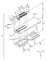
- FIG. 2 is an exploded perspective view of the antenna 10
- FIG. 3A is a plan view of antenna 50
- FIG. 3B is an enlarged view of an element portion of antenna 50
- FIG. 3C is an element portion of antenna 50 as viewed in the +Z direction.
- FIG. 3D is a perspective view of the element portion of the antenna 50 as viewed in the -Z direction
- 4A is a plan view of antenna 60
- FIG. 4B is an enlarged view of an element portion of antenna 60.
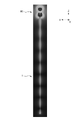
- FIG. 5A is a diagram showing the electric field distribution of the antenna 50 and FIG. 5B is a diagram showing the electric field distribution of the antenna 60.
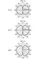
- FIG. 6A and 6B are graphs at 2400 MHz
- FIGS. 6C and 6D are graphs at 2450 MHz
- FIGS. 6E and 6F are graphs at 2500 MHz.
- 4 is a perspective view of an antenna 70
- FIG. 4 is a diagram showing electric field distribution of an antenna 70 to which the coaxial cable 1 is connected
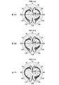
- FIG. 9A is a graph at 2400 MHz
- FIG. 9B is a graph at 2450 MHz
- FIG. 9C is a graph at 2500 MHz.
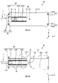
- 10A is a cross-sectional view of the line portion of the antenna 10, and FIG.
- FIG. 10B is a schematic cross-sectional view of the line portion of the antenna 10.
- FIG. 4 is a graph showing an example of frequency characteristics of the antenna 10; 1 is a diagram showing electric field distribution of an antenna 10 to which a coaxial cable 1 is connected; FIG. 13A is a graph at 2400 MHz, FIG. 13B is a graph at 2450 MHz, and FIG. 13C is a graph at 2500 MHz.
- 14A is a plan view of the antenna 80 of the second example of the present embodiment, FIG. 14A is a view of the front side of the antenna 80, and FIG. 14B is a view of the back side of the antenna 80.
- FIG. 14A is a plan view of the antenna 80 of the second example of the present embodiment
- FIG. 14A is a view of the front side of the antenna 80
- FIG. 14B is a view of the back side of the antenna 80.
- FIG. 5 is a graph showing an example of frequency characteristics of the antenna 80; 4 is a diagram showing electric field distribution of an antenna 80 to which the coaxial cable 1 is connected; FIG. 17A is a graph at 2400 MHz, FIG. 17B is a graph at 2450 MHz, and FIG. 17C is a graph at 2500 MHz.
- 18A is a graph at 5100 MHz, FIG. 18B is a graph at 5400 MHz, and FIG. 18C is a graph at 5700 MHz.
- 19A is a plan view of an antenna 90 of a first modified example of the present embodiment, FIG. 19A is a view of the front side of the antenna 90, and FIG. 19B is a view of the back side of the antenna 90.
- FIG. 19A is a plan view of an antenna 90 of a first modified example of the present embodiment
- FIG. 19A is a view of the front side of the antenna 90
- FIG. 19B is a view of the back side of the antenna 90.
- FIG. 19A
- FIG. 20A is a plan view of the antenna 100 of the second modified example of the present embodiment
- FIG. 20A is a view of the front side of the antenna 100
- FIG. 20B is a view of the back side of the antenna 100
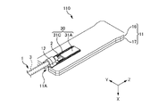
- FIG. FIG. 11 is a perspective view of an antenna 110 of a third modified example of this embodiment
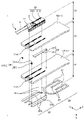
- 2 is an exploded perspective view of antenna 110
- FIG. 23A is a cross-sectional view of the line portion of the antenna 110
- FIG. 23B is a schematic cross-sectional view of the line portion of the antenna 110.
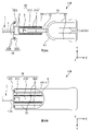
- FIG. 1 is a plan view of an antenna 10 of a first example of this embodiment.
- 1A is a view of the front side of the antenna 10
- FIG. 1B is a view of the back side of the antenna 10.
- FIG. 2 is an exploded perspective view of the antenna 10.
- the direction perpendicular to the board surface of the substrate 11 (described later) (normal direction to the board surface) is defined as the X direction.
- the direction from the front surface to the back surface of the substrate 11 is the +X direction
- the direction from the back surface to the front surface of the substrate 11 is the ⁇ X direction.
- the surface on which the cable connecting portion 12 is provided is called the "front surface”
- the surface opposite to the front surface is called the "back surface”.
- the direction in which a pair of front surface side second line portions 31A (described later) are arranged is the Y direction
- the direction in which the first line portion 21 (described later) extends is the Z direction.
- the +Y direction and the +Z direction are determined so as to form right-handed orthogonal three axes along with the +X direction described above.
- the ⁇ Y direction and ⁇ Z direction are defined as opposite directions to the +Y direction and +Z direction, respectively.
- each direction of the +X direction, +Y direction and +Z direction is represented by a line segment with an arrow in order to facilitate understanding of the direction of the antenna 10 and the like. Note that the intersection of these arrowed line segments does not mean the coordinate origin.
- the outer shape of the substrate 11 is substantially rectangular. Therefore, the Y direction is sometimes called the "width direction” and the Z direction is sometimes called the “longitudinal direction”. The Y direction is also the direction along the short side of the substrate 11 , and the Z direction is the direction along the long side of the substrate 11 .
- substantially rectangular is included in “substantially quadrilateral”.
- substantially quadrilateral means, for example, a shape consisting of four sides, and for example, at least a part of the corners may be obliquely cut away from the sides.
- a notch (concave portion) or protrusion (convex portion) may be provided on a part of the sides.
- the coaxial cable 1 is connected along the longitudinal direction of the substrate 11 as shown in FIG. Therefore, the characteristics of the shape of the substrate 11, the direction in which the coaxial cable 1 extends, and the like help the understanding of the directions and the like in the antenna 10.
- FIG. 1 the coaxial cable 1 is connected along the longitudinal direction of the substrate 11 as shown in FIG. Therefore, the characteristics of the shape of the substrate 11, the direction in which the coaxial cable 1 extends, and the like help the understanding of the directions and the like in the antenna 10.
- Antenna 10 is a broadband antenna for mobile communications.
- the antenna 10 of this embodiment is compatible with radio waves in the 2.4 GHz band and 5 GHz band used for Wi-Fi (registered trademark), Bluetooth (registered trademark), and the like.
- the antenna 10 is an antenna compatible with linearly polarized waves.
- linearly polarized waves are called vertical polarized waves when the plane of polarization is vertical to the ground, and may be called horizontal polarized waves when the plane of polarization is horizontal to the ground.
- the communication standard and frequency band with which the antenna 10 is compatible are not limited to those described above, and may be other communication standards and frequency bands.
- the antenna 10 may correspond to, for example, radio waves in at least part of the frequency bands for telematics, V2X (Vehicle to Everything: vehicle-to-vehicle communication, road-to-vehicle communication), GSM, UMTS, LTE, and 5G.
- the antenna 10 may support communication by MIMO (Multiple-Input Multiple-Output).
- MIMO communication data is transmitted from each of a plurality of antennas made up of antenna 10, and data is received at the same time by the plurality of antennas.
- the antenna 10 may be an antenna for keyless entry or an antenna for smart entry.
- a coaxial cable 1 is connected to the antenna 10 as shown in FIGS.
- a coaxial cable 1 is a feeder line connected to an antenna 10 .
- the coaxial cable 1 includes a signal line 2 as an inner conductor and a ground line 3 as an outer conductor. 1A and 2, the ground wire 3 covered with the sheath of the coaxial cable 1 is indicated by a dashed line.
- the signal line 2 is connected to a first conductor portion 20 formed on the substrate 11
- the ground line 3 is connected to a second conductor portion 30 formed on the substrate 11 .
- connecting is not limited to physically connecting, but includes “electrically connecting”.
- Electrical connecting includes, for example, connecting objects with conductors, electronic circuits, electronic parts, and the like.
- the antenna 10 has a substrate 11 , a cable connecting portion 12 , a first conductor portion 20 , a second conductor portion 30 and a power supply portion 40 .
- the substrate 11 is a plate-like member on which conductor patterns that function as the first conductor portion 20 and the second conductor portion 30 are formed.
- the substrate 11 is a printed circuit board (PCB).
- the substrate 11 is a rigid substrate, but is not limited to this, and may be a flexible substrate.
- the substrate 11 may be provided with a separate circuit element such as a filter.
- the substrate 11 has a dielectric layer 16 .
- the dielectric layer 16 is a layer made of a dielectric material.
- dielectric layer 16 is formed of a dielectric material such as glass epoxy resin used in PCBs.
- the dielectric layer 16 may be made of a dielectric material other than glass epoxy resin, such as phenol resin.
- the substrate 11 is a double-sided substrate (two-layer substrate) in which conductor patterns are formed on both sides of one dielectric layer 16, as shown in FIGS.
- the substrate 11 may be a single-sided substrate (single-layer substrate) in which a conductor pattern is formed on one side of one dielectric layer 16 .
- the substrate 11 may be configured as a three-layer substrate or a four-layer substrate by having a dielectric layer 17 separate from the dielectric layer 16, like the antenna 110 shown in FIGS. It may be configured as a multilayer substrate as described above.
- the layer on the front surface side of the substrate 11, on which conductor patterns and the like are formed may be referred to as the "first layer 13".
- the layer on the back surface side of the substrate 11, on which conductor patterns and the like are formed is sometimes referred to as a "second layer 14".
- the cable connection portion 12 is a member for connecting the coaxial cable 1 to the antenna 10.
- the cable connecting portion 12 is configured by a ring-shaped holding member that holds the end of the coaxial cable 1, as shown in FIG. Then, the holding member is joined to the substrate 11 by soldering.
- the cable connecting portion 12 is not limited to the above aspect, and may be configured by a connector, for example.
- the cable connecting portion 12 is provided at the end of the substrate 11 on the -Z direction side. Thereby, the coaxial cable 1 is connected to the end of the substrate 11 .
- the substrate 11 has a notch portion 11A as shown in FIGS. 1B and 2.
- FIG. The cutout portion 11A is a cutout region in the substrate 11 .
- the cable connection portion 12 is located in the notch portion 11A.
- a part of the holding member that holds the end of the coaxial cable 1 is arranged inside the notch 11A, and both sides of the holding member in the Y direction are soldered to the edge of the notch of the substrate 11. spliced.
- the coaxial cable 1 is positioned inside the notch 11A, and the thickness (that is, the size in the X direction) of the antenna 10 to which the coaxial cable 1 is connected can be reduced, and the antenna 10 can be miniaturized. . Also, the antenna 10 can be made thinner. Furthermore, since the holding member that holds the end of the coaxial cable 1 can be arranged so as to straddle the notch, the holding member can be easily soldered to the substrate 11 .
- the substrate 11 has the notch portion 11A and the cable connection portion 12 is positioned in the notch portion 11A, thereby facilitating the connection of the coaxial cable 1 to the antenna 10 and the antenna 10 to which the coaxial cable 1 is connected. can be made smaller and thinner.
- the first conductor portion 20 is a conductor portion connected to the signal line 2 of the coaxial cable 1 .
- the first conductor portion 20 includes a first line portion 21 provided on the first layer 13 (that is, the layer on the front surface side of the substrate 11) and a second layer 14 (that is, the layer on the back surface side of the substrate 11). ) and a first extending portion 22 provided in the .
- a detailed description of the first conductor portion 20 will be given later.
- the second conductor portion 30 is a conductor portion connected to the ground wire 3 of the coaxial cable 1 .
- the second conductor portion 30 has a second line portion 31 and a second extending portion 32 .
- the second line portion 31 connects the second line portion 31A on the front side, the second line portion 31B on the back side, and the second line portion 31A and the second line portion 31B.
- the second extending portion 32 has a body portion 32A, an additional portion 32B, and a through hole 32C connecting the body portion 32A and the additional portion 32B.
- the first conductor portion 20 and the second conductor portion 30 are conductor patterns formed on the substrate 11 and function as elements that resonate in the frequency band of radio waves corresponding to the antenna 10 .
- the thickness of the antenna 10 as a whole is reduced, so that the antenna 10 can be made thinner, and the degree of freedom in arranging the antenna 10 is improved.
- the element of the antenna 10 can be easily held.
- the feeding section 40 is an area including the feeding point of the antenna 10 .
- the power feeding section 40 is positioned between the first conductor section 20 and the second conductor section 30 as shown in FIG. 1B.
- the first conductor portion 20 and the second conductor portion 30 are provided so as to operate as a sleeve dipole antenna.
- the antenna 10 can be made smaller and thinner, and leakage current can be suppressed.
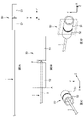
- FIG. 3 is a diagram of the antenna 50. As shown in FIG. 3A is a plan view of the antenna 50, FIG. 3B is an enlarged view of the element portion of the antenna 50, and FIG. 3C is a perspective view of the element portion of the antenna 50 when viewed in the +Z direction. 3D is a perspective view of the element portion of antenna 50 as viewed in the -Z direction.
- the inventor first focused on the sleeve dipole antenna as an antenna that is advantageous for suppressing leakage current.
- the antenna 50 shown in FIG. 3 is a common sleeve dipole antenna.
- the antenna 50 is connected to the coaxial cable 1 as shown in FIG.
- the coaxial cable 1 connected to the antenna 50 has a signal line 2 as an inner conductor and a ground line 3 as an outer conductor, like the coaxial cable 1 connected to the antenna 10 described above. Consists of
- the antenna 50 has a first element 51 and a second element 52 .
- the first element 51 is an element connected to the signal line 2 of the coaxial cable 1.
- the first element 51 has the shape of an elongated sleeve opening in the +Z direction, as shown in FIG. 3D.
- the second element 52 is an element connected to the ground wire 3 of the coaxial cable 1.
- the second element 52 has the shape of an elongated sleeve opening in the -Z direction, as shown in Figure 3C.
- each of the first element 51 and the second element 52 has a cylindrical shape with a bottom surface, as shown in FIG.
- the first element 51 has a bottom surface on the -Z direction side
- the second element 52 has a bottom surface on the +Z direction side.
- the sleeves forming the first element 51 and the sleeves forming the second element 52 are arranged side by side so that the central axes of the respective sleeves are the same. be done.
- the first element 51 and the second element 52 are arranged side by side in the longitudinal direction.
- the coaxial cable 1 is connected between the first element 51 and the second element 52 as shown in FIG. 3B. That is, the signal line 2 of the coaxial cable 1 is connected to the end of the first element 51 on the -Z direction side (the second element 52 side), and the ground line 3 of the coaxial cable 1 is connected to the +Z direction of the second element 52. side (first element 51 side).
- the coaxial cable 1 connected to the first element 51 and the second element 52 passes through the inside of the sleeve of the second element 52 and extends in the -Z direction.
- the impedance is highest at the end on the -Z direction side indicated by the dashed line A in FIG. 3B. Therefore, in the antenna 50, by arranging the coaxial cable 1 to pass through the inside of the sleeve of the second element 52, leakage current flowing to the coaxial cable 1 side can be suppressed.
- the longitudinal direction of the antenna 50 and the direction of the coaxial cable 1 extending from the antenna 50 are the same. Therefore, it is particularly advantageous to employ the antenna 50 as a sleeve dipole antenna when it is desired to arrange the coaxial cable 1 to extend from the longitudinal ends of the antenna 50 .
- the inventor then came up with the idea of reducing the thickness of the antenna 50 in order to mount the antenna 50 as a sleeve dipole antenna on the substrate 11 . Specifically, the inventor has the idea of cutting the first element 51 and the second element 52 of the antenna 50 along the plane indicated by the dashed line and removing both ends, as shown in FIG. 3D.
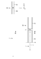
- FIG. 4 is a diagram of the antenna 60.
- FIG. 4A is a plan view of the antenna 60
- FIG. 4B is an enlarged view of the element portion of the antenna 60.
- FIG. 4A is a plan view of the antenna 60
- FIG. 4B is an enlarged view of the element portion of the antenna 60.
- the antenna 60 is a model antenna obtained by cutting the first element 51 and the second element 52 of the antenna 50 along the plane indicated by the dashed line in FIG. 3D and removing both ends.
- the antenna 60 is connected to the coaxial cable 1 as shown in FIG.
- the coaxial cable 1 connected to the antenna 60 has a signal line 2 as an inner conductor and a ground line 3 as an outer conductor, like the coaxial cable 1 connected to the antenna 50 described above. Consists of
- the first element 61 is an element connected to the signal line 2 of the coaxial cable 1. As shown in FIG. 4B, the first element 61 has a shape obtained by cutting an elongated sleeve opening in the +Z direction.
- the second element 62 is an element connected to the ground wire 3 of the coaxial cable 1.
- the second element 62 has the shape of an elongated sleeve cut open in the -Z direction, as shown in FIG. 4B.
- each of the first element 61 and the second element 62 has a shape like a tuning fork placed on the YZ plane, as shown in FIG.
- the features of the antenna 60 are the same as those of the antenna 50 except that the first element 51 and the second element 52 of the antenna 50 are cut along the plane indicated by the dashed line in FIG. 3D and both ends are removed. That is, in the antenna 60, as shown in FIGS. 4A and 4B, the partial sleeve forming the first element 61 and the partial sleeve forming the second element 62 are each a partial sleeve. are arranged side by side so that their central axes are the same. In other words, the first element 61 and the second element 62 are arranged side by side in the longitudinal direction.
- the coaxial cable 1 is connected between the first element 61 and the second element 62 as shown in FIG. 4B. That is, the signal line 2 of the coaxial cable 1 is connected to the end of the first element 61 in the -Z direction (second element 62 side), and the ground line 3 of the coaxial cable 1 is connected to the second element 62 in the +Z direction. side (first element 61 side).
- the coaxial cable 1 connected to the first element 61 and the second element 62 passes through the inside of the partial sleeve of the second element 62 and extends in the -Z direction.
- the second element 62 of the antenna 60 also has the highest impedance at the end on the -Z direction side indicated by the dashed line B in FIG. 4B. Therefore, in the antenna 60 as well as in the antenna 50, the coaxial cable 1 is disposed so as to pass through the partial sleeve of the second element 62, thereby suppressing the leakage current flowing to the coaxial cable 1 side. be able to.
- the longitudinal direction of the antenna 60 and the direction of the coaxial cable 1 extending from the antenna 60 are the same. Therefore, employing the antenna 60 is particularly advantageous if the coaxial cable 1 is to be arranged to extend from the longitudinal ends of the antenna 60 .
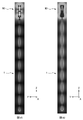
- FIG. 5 is a diagram showing electric field distributions of the antenna 50 and the antenna 60 to which the coaxial cable 1 is connected.
- 5A is a diagram showing the electric field distribution of the antenna 50
- FIG. 5B is a diagram showing the electric field distribution of the antenna 60.
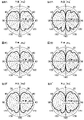
- FIG. 6 is a graph showing an example of the directivity of the antennas 50 and 60.
- FIGS. 6A and 6B are graphs at 2400 MHz
- FIGS. 6C and 6D are graphs at 2450 MHz
- FIGS. 6E and 6F are graphs at 2500 MHz.
- FIGS. 6A, 6C and 6E show the directivity of the antenna 50
- FIGS. 6B, 6D and 6F show the directivity of the antenna 60.
- FIG. 6A, 6C and 6E show the directivity of the antenna 50
- FIGS. 6B, 6D and 6F show the directivity of the antenna 60.
- FIG. 6A, 6C and 6E show the directivity of the antenna 50
- the electric field distribution shown in FIG. 5 visually represents the leakage current generated in the antenna. Specifically, the leakage current generated in the antenna appears as a pattern with a plurality of constrictions on the coaxial cable 1 . As the influence of leakage current increases, ripples occur in the directivity of the antenna shown in FIG.
- the antenna 50 has less leakage current and good directivity.
- the antenna 60 has more leakage current than the antenna 50, and the influence of the leakage current causes ripples in the directivity in the 2.4 GHz band. is occurring. That is, the antenna 60 has more leakage current than the antenna 50 .
- the antenna 60 In the antenna 50, the entire periphery of the coaxial cable 1 was surrounded by the end of the second element 52 with the highest impedance. However, in the antenna 60 , the second element 62 has a shape obtained by removing a part of the second element 52 , so the coaxial cable 1 is not entirely surrounded by the ends of the second element 62 . That is, in the antenna 60 , the portion where the second element 62 has the highest impedance is not closed around the coaxial cable 1 . Therefore, it is considered that the antenna 60 is less effective in suppressing leakage current than the antenna 50 .
- the inventor focused on improving the effect of suppressing the leakage current by providing the super top portion to the antenna 60 .
- FIG. 7 is a perspective view of the antenna 70.
- the antenna 70 further has a supertop portion 71 in addition to the first element 61 and the second element 62 similar to the antenna 60 described above.
- the super top portion 71 is a member that suppresses leakage current of the antenna 70 .
- the super top portion 71 has the shape of an elongated sleeve opening in the +Z direction.
- the super top portion 71 has a cylindrical shape and is located on the -Z direction side with respect to the second element 62, as shown in FIG.
- FIG. 8 is a diagram showing the electric field distribution of the antenna 70 to which the coaxial cable 1 is connected.
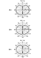
- 9 is a graph showing an example of the directivity of the antenna 70.
- FIG. 9A is a graph at 2400 MHz
- FIG. 9B is a graph at 2450 MHz
- FIG. 9C is a graph at 2500 MHz.
- the antenna 70 has less leakage current and improved directivity compared to the antenna 60 shown in FIGS. 5B, 6B, 6D and 6F. . Therefore, the antenna 10 of the present embodiment aims at the characteristics of the antenna 70 in these verification results.
- the inventor mounted the antenna 10 of the present embodiment by forming conductor patterns (the first conductor portion 20 and the second conductor portion 30) on the substrate 11 based on the antenna 70 described above. That is, in the antenna 10 of this embodiment, the first conductor portion 20 and the second conductor portion 30 are provided so as to operate as a sleeve dipole antenna. Moreover, in the antenna 10 of the present embodiment, at least part of the second conductor portion 30 also has a structure that suppresses leakage current. As a result, the antenna can be made smaller and thinner, and leakage current can be suppressed.
- the first conductor portion 20 has a first line portion 21 , a first extending portion 22 and a through hole 24 .
- the first line portion 21 is a portion where a configuration corresponding to the signal line 2 of the coaxial cable 1 is mounted on the substrate 11 .
- the first line portion 21 is formed on the first layer 13 of the substrate 11 (that is, the layer on the front surface side of the substrate 11), as shown in FIGS. 1A and 2 .
- the ⁇ Z direction end of the first line portion 21 is connected to the signal line 2
- the +Z direction end of the first line portion 21 is connected to the first extending portion 22 via the through hole 24 . It is connected.
- the first extension part 22, along with the second extension part 32 described later, is mounted on the substrate 11 as an element that resonates in the radio wave frequency band (for example, 2.4 GHz band and 5 GHz band) corresponding to the antenna 10. It is a part. Therefore, the first extending portion 22 is formed to have a length and width corresponding to the operating wavelength of the radio wave frequency band corresponding to the antenna 10 (for example, the wavelength in the 2.4 GHz band).
- the electrical length of the first extending portion 22 from the feeding portion 40 is formed so as to resonate in the frequency band of radio waves corresponding to the antenna 10 .
- the electrical length of the first extending portion 22 from the feeding portion 40 is formed to correspond to a quarter of the wavelength in the frequency band of radio waves corresponding to the antenna 10 .
- a quarter of the wavelength in the frequency band of radio waves corresponding to the antenna 10 is not limited to an exact value, and may be a value that resonates in a desired frequency band. This is because the wavelength in the frequency band of the radio wave corresponding to the antenna 10 is not necessarily represented by a divisible integer, and the actual electrical length of the first extending portion 22 from the feeding portion 40 varies due to various factors. . Note that the electrical length of the first extending portion 22 from the feeding portion 40 is 4 times the wavelength in the frequency band of the radio wave corresponding to the antenna 10 if it is formed so as to resonate in the frequency band of the radio wave corresponding to the antenna 10 . It does not have to be formed to correspond to 1/10.
- the first extending portion 22 is formed to extend from the feeding portion 40 to both sides in the Y direction, as shown in FIG. 1B.
- the electrical length of the first extending portions 22 extending on both sides in the Y direction from each feeding portion 40 is formed to correspond to a quarter of the wavelength in the corresponding radio wave frequency band of the antenna 10 .
- the first extending portion 22 is formed on the second layer 14 of the substrate 11 (that is, the layer on the back side of the substrate 11), as shown in FIGS. 1B and 2 .
- the ⁇ Z direction end of the first extending portion 22 is connected to the first line portion 21 via a through hole 24 .
- the first extending portion 22 has a bent portion 23 .
- the bent portion 23 is a portion that is bent and further extended from the +Z direction side end of the first extended portion 22 .
- the electrical length of the first extending portion 22 from the feeding portion 40 can be ensured to be sufficient for resonance in the corresponding radio wave frequency band of the antenna 10 .
- the bent portion 23 is not limited to a bent shape as long as it has a shape that further extends the length of the first extending portion 22 . That is, the bent portion 23 may have a curved shape, a bent shape, a meandering shape, or the like.
- the bent portion 23 is formed to bend inwardly of the first extending portion 22, but may be formed to be bent outwardly. Also, the bent portion 23 may be formed so as to extend from the first extending portion 22 other than the end portion on the +Z direction side. Furthermore, the bent portion 23 is formed in the same shape on each of the first extending portions 22 extending on both sides in the Y direction, but may be formed on only one of the first extending portions 22 . In addition, bent portions 23 having different shapes may be formed for the first extending portions 22 extending on both sides in the Y direction.
- the end of the first extending portion 22 extending in the +Y direction is formed with a bending portion 23 that is bent inward, and the end of the first extending portion 22 extending in the -Y direction is bent outward.
- a bent portion 23 may be formed.
- the through hole 24 is a portion that connects the first line portion 21 formed on the first layer 13 of the substrate 11 and the first extending portion 22 formed on the second layer 14 of the substrate 11 .
- Through hole 24 electrically connects first line portion 21 and first extension portion 22 .
- the second conductor portion 30 has a second line portion 31 and a second extending portion 32 .
- the second line portion 31 is a portion where a configuration corresponding to the ground wire 3 of the coaxial cable 1 is mounted on the substrate 11 . As shown in FIGS. 1 and 2, the second line portion 31 is formed on the first layer 13 of the substrate 11 (that is, the layer on the front surface side of the substrate 11). 2 line portion 31A, and back surface side second line portion 31B formed in the second layer 14 of the substrate 11 (that is, the layer on the back surface side of the substrate 11).
- the front surface side second line portion 31A is formed to extend in the Z direction along the first line portion 21 of the first conductor portion 20 . Further, a pair of front surface side second line portions 31A are formed on both sides of the first line portion 21 in the Y direction. The -Z direction side ends of the pair of front surface side second line portions 31 A are connected to the ground line 3 .
- the back surface side second line portion 31B is formed to extend in the Z direction.
- the +Z direction side end of the rear surface side second line portion 31B is connected to the body portion 32A of the second extending portion 32 .
- the rear surface side second line portion 31B is provided between the cable connection portion 12 and the power supply portion 40 .
- the second line portion 31 is arranged parallel to the first line portion 21 .
- the first line portion 21 and the second line portion 31 may be non-parallel, and at least one of them may be curved. or meandering.
- the second line portion 31 further has a through hole 31C.
- the through hole 31C connects the front surface side second line portion 31A formed in the first layer 13 of the substrate 11 and the back surface side second line portion 31B formed in the second layer 14 of the substrate 11. It is a part to do.
- the through hole 31C electrically connects the front surface side second line portion 31A and the back surface side second line portion 31B.
- a plurality of through holes 31C are arranged side by side in the Z direction along the front surface side second line portion 31A.
- Each through hole 31C connects the front surface side second line portion 31A and the back surface side second line portion 31B.
- the second extending portion 32 having the main body portion 32A, the additional portion 32B, and the through hole 32C, together with the first extending portion 22, corresponds to the radio wave frequency band of the antenna 10 (for example, 2.4 GHz band and 5 GHz band).
- the second extending portion 32 is formed to have a length and width corresponding to the operating wavelength of the radio frequency band corresponding to the antenna 10 (for example, the wavelength in the 2.4 GHz band).
- the electrical length of the second extending portion 32 from the feeding portion 40 is formed so as to resonate in the radio wave frequency band corresponding to the antenna 10 .
- the electrical length of the second extending portion 32 from the feeding portion 40 is formed to correspond to a quarter of the wavelength in the frequency band of radio waves corresponding to the antenna 10 .
- the electrical length of the second extending portion 32 from the feeding portion 40 is 4 times the wavelength in the frequency band of the radio waves corresponding to the antenna 10 if it is formed so as to resonate in the frequency band of radio waves corresponding to the antenna 10 . It does not have to be formed to correspond to 1/10.
- the second extension part 32 is formed to extend from the feeding part 40 to both sides in the Y direction, as shown in Figs. 1B and 2 .
- the second extending portion 32 extends from the power supply portion 40 and is positioned so as to sandwich the second back surface side line portion 31B.
- the electrical length of the second extending portions 32 extending on both sides in the Y direction from each feeding portion 40 is formed to correspond to a quarter of the wavelength in the corresponding radio wave frequency band of the antenna 10 .
- the second extending portion 32 has a main body portion 32A, an additional portion 32B, and a through hole 32C.
- the body portion 32A is a portion of the second extending portion 32 formed on the second layer 14 of the substrate 11 (that is, the layer on the back side of the substrate 11).
- the additional portion 32B is a portion additionally provided to the main body portion 32A in order to ensure an electrical length required for resonance in the frequency band of radio waves corresponding to the antenna 10 .
- the additional portion 32B is formed on the first layer 13 of the substrate 11 (that is, the layer on the front surface side of the substrate 11).
- the additional portion 32B may be formed on the second layer 14 of the substrate 11 instead of being formed on the first layer 13 of the substrate 11 . That is, the additional portion 32B may be formed in the same layer as the layer in which the body portion 32A is formed, like the bent portion 23 of the first extending portion 22 . In this case, the additional portion 32B is formed, for example, so as to bend inward from the end portion of the main body portion 32A. However, the additional portion 32B may be coupled with the second line portion 31 (back surface side second line portion 31B) due to its proximity, which may adversely affect the characteristics.
- the additional portion 32B in a layer different from the layer in which the main body portion 32A is formed, the electrical length necessary for resonating in the frequency band of radio waves corresponding to the antenna 10 is ensured and the second line is provided. It is possible to suppress adverse effects on the characteristics due to proximity to the portion 31 .
- the through-hole 32C is a portion that connects the additional portion 32B formed on the first layer 13 of the substrate 11 and the main portion 32A formed on the second layer 14 of the substrate 11 .
- the through hole 32C electrically connects the additional portion 32B and the main body portion 32A.
- the first extending portion 22 of the first conductor portion 20 and the second extending portion 32 of the second conductor portion 30 are formed in the same second layer of the substrate 11. Located at 14. In the region where the first conductor portion 20 and the second conductor portion 30 located on the same second layer 14 face each other, the first conductor portion 20 and the second conductor portion 30 have a self-similar shape portion 41 . This makes it possible to realize the antenna 10 that supports a wide band, particularly in the 5 GHz band.
- a "self-similar shape” is a shape whose shape is similar even if the scale (size ratio) is changed.
- the first conductor portion 20 and the second conductor portion 30 may not have the self-similar shape portion 41 .
- first line portion 21 and the second line portion 31 may be simply referred to as a "line portion”.
- first extension portion 22 and the second extension portion 32 may be simply referred to as an "extension portion”.
- the layer of the substrate 11 where the cable connection portion 12 is located that is, the first layer 13
- part of the second conductor portion 30 are located.
- the layers of the substrate 11 i.e., the second layer 14
- the substrate 11 can be miniaturized and the VSWR characteristic can be improved.
- FIG. 10 is a diagram of the line portion of the antenna 10.
- FIG. 10A is a cross-sectional view of the line portion of the antenna 10
- FIG. 10B is a schematic cross-sectional view of the line portion of the antenna 10. As shown in FIG.
- the line portion of the antenna 10 of the present embodiment is composed of a rear surface side second line portion 31B connected to the ground line 3 and a first line portion 21 connected to the signal line 2. It constitutes a structure similar to a microstrip line. Furthermore, the line portion of the antenna 10 of the present embodiment further has a through hole 31C as a conductor functioning as a ground on the side surface.
- the first line portion 21 connected to the signal line 2 and the second line portion 31 connected to the ground line 3 have a coaxial structure. Of these, the shape is such that half is configured.
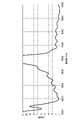
- FIG. 11 is a graph showing an example of frequency characteristics of the antenna 10.
- the horizontal axis represents frequency
- the vertical axis represents voltage standing wave ratio (VSWR).
- the calculation result for the antenna 10 is indicated by a solid line.
- the antenna 10 has good VSWR characteristics in the 2.4 GHz band, particularly in the range of 2400 MHz to 2500 MHz, as shown in FIG. Further, as shown in FIG. 11, the antenna 10 has good VSWR characteristics even in the range of 5500 to 6000 MHz in the 5 GHz band.
- FIG. 12 is a diagram showing the electric field distribution of the antenna 10 to which the coaxial cable 1 is connected.
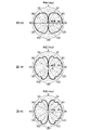
- 13 is a graph showing an example of the directivity of the antenna 10.
- FIG. 13A is a graph at 2400 MHz
- FIG. 13B is a graph at 2450 MHz
- FIG. 13C is a graph at 2500 MHz.
- the leakage current of the antenna 10 is suppressed to some extent by providing the first conductor portion 20 and the second conductor portion 30 so as to operate as a sleeve dipole antenna.
- directivity deteriorates near 2500 MHz, which is the upper limit of the 2.4 GHz band.
- the antenna 10 has room for improvement with respect to the target characteristics of the antenna 70 .
- the influence given by the electrical length of the element (extended portion) is dominant. Therefore, the influence of the wavelength shortening effect of the dielectric layer 16 of the substrate 11 is relatively small.
- the influence of the dielectric layer 16 of the substrate 11 between the line portion and the extension portion becomes greater. As a result, wavelength shortening is more likely to occur.
- the leakage current of the antenna 10 can be further suppressed by adjusting the electrical length of the structure that suppresses the leakage current independently of the electrical length of the extension portion, as in the antenna 80 to be described later.
- the "structure for suppressing leakage current" is sometimes referred to as a "supertop structure.”
- FIG. 14B is a view of the back side of the antenna 80.
- the configuration of the antenna 80 of the second example is the same as that of the antenna 10 of the first example, except that the second extending portion 32 of the second conductor portion 30 further has an adjusting portion 33 .
- the adjusting portion 33 is an additional conductor portion provided on the rear surface side second line portion 31B side of the main body portion 32A of the second extending portion 32 .
- the distance between the main body portion 22A and the rear surface side second line portion 31B is reduced, and the path length L and the capacitance C inside the speltop structure change.
- the antenna 80 of the second example is an antenna obtained by adjusting the Speltop structure independently of the antenna 10 of the first example.
- FIG. 15 is a graph showing an example of frequency characteristics of the antenna 80.
- the horizontal axis represents frequency
- the vertical axis represents voltage standing wave ratio (VSWR).
- the calculation result for the antenna 80 is indicated by a solid line.
- the antenna 80 has good VSWR characteristics in the 2.4 GHz band, especially in the range of 2400 MHz to 2500 MHz. Also, like the antenna 10, the antenna 80 has good VSWR characteristics even in the range of 5500 to 6000 MHz in the 5 GHz band.
- FIG. 16 is a diagram showing the electric field distribution of the antenna 80 to which the coaxial cable 1 is connected.
- FIG. 17 is a graph showing an example of the directivity of the antenna 80.
- FIG. 17A is a graph at 2400 MHz
- FIG. 17B is a graph at 2450 MHz
- FIG. 17C is a graph at 2500 MHz.
- antenna 80 comes fairly close to the characteristics of antenna 70 shown in FIGS. 16 and 17.
- FIG. 18 is a graph showing an example of the directivity of the antenna 80.
- FIG. 18A is a graph at 5100 MHz
- FIG. 18B is a graph at 5400 MHz
- FIG. 18C is a graph at 5700 MHz.
- the leakage current of the antenna 80 is suppressed to some extent even in the 5 GHz band, but compared with the 2.4 GHz band shown in FIGS. ing.
- the 5 GHz band is expected to operate as a traveling wave, compared to the 2.4 GHz band, there is a greater tolerance for leakage current, and the need for independent adjustment of the Speltop structure is not so high.
- the first conductor portion 20 and the second conductor portion 30 have different shapes.
- the first conductor portion 20 and the second conductor portion 30 may have the same shape like the antenna 90 of the first modified example described later.
- the first extending portion 22 of the first conductor portion 20 has the bent portion 23 that is bent from the end portion and further extended.
- the antenna 90 of the first modified example may have the same configuration as the second extending portion 32 of the second conductor portion 30 .
- FIG. 19 is a plan view of the antenna 90 of the first modified example of this embodiment.
- 19A is a view of the front side of the antenna 90
- FIG. 19B is a view of the back side of the antenna 90.
- FIG. 19A is a view of the front side of the antenna 90
- FIG. 19B is a view of the back side of the antenna 90.
- the first extending portion 22 has a main body portion 22A, an additional portion 22B, and a through hole 25.
- the body portion 22A is a portion of the first extending portion 22 formed on the second layer 14 of the substrate 11 (that is, the layer on the back side of the substrate 11).
- the additional portion 22B is a portion additionally provided to the main body portion 22A in order to ensure an electrical length required for resonance in the frequency band of radio waves corresponding to the antenna 10 .
- the additional portion 22B is formed on the first layer 13 of the substrate 11 (that is, the layer on the front surface side of the substrate 11).
- the through hole 25 is a portion that connects the additional portion 22B formed on the first layer 13 of the substrate 11 and the main portion 22A formed on the second layer 14 of the substrate 11 .
- Through holes 25 electrically connect additional portion 22B and main body portion 22A.
- the configuration of the antenna 90 of the first modified example is the same as that of the antenna 80 except that the first extending portion 22 has the same outer shape as the second conductor portion 30 .
- the first extending portion 22 of the first conductor portion 20 and the second extending portion 32 of the second conductor portion 30 are located on the same second layer 14 of the substrate 11 .
- the first extending portion 22 and the second extending portion 32 do not have to be located in the same layer.
- the first extension portion 22 and the second extension portion 32 may be located in different layers, like the antenna 100 of the second modified example described later.
- FIG. 20 is a plan view of the antenna 100 of the second modified example of this embodiment.
- 20A is a view of the front side of the antenna 100
- FIG. 20B is a view of the back side of the antenna 100.
- FIG. 20A is a view of the front side of the antenna 100
- FIG. 20B is a view of the back side of the antenna 100.
- the first extending portion 22 is formed on the first layer 13 of the substrate 11 (that is, the layer on the front side of the substrate 11).
- the ⁇ Z direction side end of the first extending portion 22 is connected to the first line portion 21 . Therefore, through holes 24 do not exist.
- the antenna 100 of the second modified example has the same configuration as the antenna 80 except that the first extending portion 22 of the first conductor portion 20 is formed in the first layer 13 of the substrate 11 and the through hole 24 does not exist. .
- the substrate 11 is a double-sided substrate (two-layer substrate) in which conductor patterns are formed on both sides of one dielectric layer 16 .
- it may be configured as a three-layer substrate by having a dielectric layer 17 different from the dielectric layer 16 .
- FIG. 21 is a perspective view of the antenna 110 of the third modified example of this embodiment.
- FIG. 22 is an exploded perspective view of the antenna 110.
- the substrate 11 has the dielectric layer 16 and the cable connecting part 12, and also has the dielectric layer 17 different from the dielectric layer 16. have more. That is, the substrate 11 is configured as a three-layer substrate.
- the layer between the dielectric layer 16 and the dielectric layer 17 may be called "third layer 15".
- the first line portion 21 and the additional portion 32B of the second extending portion 32 are formed on the third layer 15 .
- Other configurations of the antenna 110 of the third modified example are similar to the configuration of the antenna 80 .
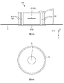
- FIG. 23 is a diagram of the line portion of the antenna 110.
- FIG. 23A is a cross-sectional view of the line portion of the antenna 110
- FIG. 23B is a schematic cross-sectional view of the line portion of the antenna 110. As shown in FIG.
- the line portions of the antenna 110 of the third modified example include a rear side second line portion 31B connected to the ground line 3 and a first line portion 21 connected to the signal line 2.
- a structure similar to a microstrip line is constructed by Furthermore, the line portion of the antenna 110 of the third modified example further has a through hole 31C as a conductor functioning as a ground on the side surface.
- the first line portion 21 connected to the signal line 2 and the second line portion 31 connected to the ground line 3 are coaxially connected. All of the structures are configured shapes.
- the antenna 10 shown in FIG. 10B has a shape in which half of the coaxial structure is configured, whereas the antenna 110 of the third modification has a shape in which the entire coaxial structure is configured. For this reason, the antenna 110 of the third modified example has a superior function as a line portion compared to the antenna 10 .
- the antennas 10, 80, 90, 100 and 110 of the present embodiment are formed on the substrate 11 and the substrate 11 as shown in FIGS.
- a first conductor portion 20 and a second conductor portion 30 are provided.
- the first conductor portion 20 is connected to the signal line 2
- the second conductor portion 30 is connected to the ground line 3
- the first conductor portion 20 and the second conductor portion 30 operate as a sleeve dipole antenna.
- the antenna can be made smaller and thinner, and leakage current can be suppressed.
- the coaxial cable 1 is connected as shown in FIGS.
- a cable connection portion 12 is further provided, and the cable connection portion 12 is provided at an end portion of the substrate 11 .
- the antenna can be made smaller and thinner, and leakage current can be suppressed.
- the coaxial cable 1 can be easily connected to the substrate 11, and the antenna can be miniaturized.
- the cable connection portion 12 is positioned as shown in FIGS.
- the first layer 13 of the substrate 11 and the second layer 14 of the substrate 11 on which at least part of the second conductor portion 30 (for example, the body portion 32A of the second extension portion 32) is located are different from each other. Thereby, the substrate 11 can be miniaturized and the VSWR characteristic can be improved.
- the antennas 10, 80, 90, 100 and 110 of the present embodiment for example, as shown in FIGS. It is provided so as to extend from one second layer 14 of the substrate 11 to another first layer 13 . Thereby, the electrical length required for the antenna to resonate can be ensured.
- the antennas 10, 80, 90 and 110 of the present embodiment for example, as shown in FIGS. (eg, the first extension 22 ) and at least a portion of the second conductor section 30 (eg, the second extension 32 ) are located on the same second layer 14 of the substrate 11 .
- FIGS. eg, the first extension 22
- the second conductor section 30 eg, the second extension 32
- the first conductor portion 20 and the second conductor portion 30 have a self-similar shape portion 41 in a predetermined region where the first conductor portion 20 and the second conductor portion 30 face each other. As a result, it is possible to realize an antenna that supports a wide band.
- the substrate 11 is the coaxial cable 1 as shown in FIGS.
- the substrate 11 has a cable connection portion 12 to which the second conductor portion 30 is connected, and the second conductor portion 30 extends from the back side second line portion 31B provided between the cable connection portion 12 and the power supply portion 40 and the power supply portion 40, and a pair of second extending portions 32 (main body portion 32A) located so as to sandwich the rear surface side second line portion 31B.
- the antenna can be miniaturized and leakage current can be suppressed.
Landscapes
- Details Of Aerials (AREA)
Abstract
Priority Applications (4)
| Application Number | Priority Date | Filing Date | Title |
|---|---|---|---|
| JP2023505279A JP7774041B2 (ja) | 2021-03-08 | 2022-02-24 | アンテナ |
| CN202280019769.0A CN117296207A (zh) | 2021-03-08 | 2022-02-24 | 天线 |
| EP22766836.5A EP4307481A1 (fr) | 2021-03-08 | 2022-02-24 | Antenne |
| US18/280,684 US12463343B2 (en) | 2021-03-08 | 2022-02-24 | Antenna having first and second conductor parts with sleeves |
Applications Claiming Priority (2)
| Application Number | Priority Date | Filing Date | Title |
|---|---|---|---|
| US202163158010P | 2021-03-08 | 2021-03-08 | |
| US63/158,010 | 2021-03-08 |
Publications (1)
| Publication Number | Publication Date |
|---|---|
| WO2022190876A1 true WO2022190876A1 (fr) | 2022-09-15 |
Family
ID=83227738
Family Applications (1)
| Application Number | Title | Priority Date | Filing Date |
|---|---|---|---|
| PCT/JP2022/007557 Ceased WO2022190876A1 (fr) | 2021-03-08 | 2022-02-24 | Antenne |
Country Status (5)
| Country | Link |
|---|---|
| US (1) | US12463343B2 (fr) |
| EP (1) | EP4307481A1 (fr) |
| JP (1) | JP7774041B2 (fr) |
| CN (1) | CN117296207A (fr) |
| WO (1) | WO2022190876A1 (fr) |
Citations (8)
| Publication number | Priority date | Publication date | Assignee | Title |
|---|---|---|---|---|
| GB2317994A (en) * | 1996-10-02 | 1998-04-08 | Northern Telecom Ltd | A multi-resonant antenna |
| JP2005192049A (ja) * | 2003-12-26 | 2005-07-14 | Anten Corp | アンテナ |
| US20060017622A1 (en) * | 2004-03-09 | 2006-01-26 | Centurion Wireless Technologies, Inc. | Multi-band omni directional antenna |
| JP2008109214A (ja) * | 2006-10-23 | 2008-05-08 | Matsushita Electric Ind Co Ltd | アンテナ装置 |
| JP2014161008A (ja) * | 2013-01-24 | 2014-09-04 | Noise Laboratory Co Ltd | アンテナ |
| JP2016005028A (ja) * | 2014-06-13 | 2016-01-12 | ヤマハ株式会社 | 平面漏洩伝送路 |
| JP2019062372A (ja) | 2017-09-26 | 2019-04-18 | 株式会社Soken | 複合アンテナ装置 |
| JP2020098979A (ja) * | 2018-12-17 | 2020-06-25 | パナソニックIpマネジメント株式会社 | アンテナ装置 |
Family Cites Families (10)
| Publication number | Priority date | Publication date | Assignee | Title |
|---|---|---|---|---|
| JPH10107533A (ja) | 1996-10-02 | 1998-04-24 | Toa Corp | アンテナ |
| US6337666B1 (en) * | 2000-09-05 | 2002-01-08 | Rangestar Wireless, Inc. | Planar sleeve dipole antenna |
| JP2004048109A (ja) * | 2002-07-08 | 2004-02-12 | Sansei Denki Kk | 無給電素子付きスロットボータイアンテナ、および無給電素子付きスロットボータイアレーアンテナ |
| US6765539B1 (en) * | 2003-01-24 | 2004-07-20 | Input Output Precise Corporation | Planar multiple band omni radiation pattern antenna |
| TWI253781B (en) * | 2005-08-03 | 2006-04-21 | Wistron Neweb Corp | Monopole antenna |
| US7339542B2 (en) * | 2005-12-12 | 2008-03-04 | First Rf Corporation | Ultra-broadband antenna system combining an asymmetrical dipole and a biconical dipole to form a monopole |
| JP2008078752A (ja) * | 2006-09-19 | 2008-04-03 | Mitsumi Electric Co Ltd | アンテナ装置 |
| WO2010059794A2 (fr) * | 2008-11-20 | 2010-05-27 | Armen Kazanchian | Antenne avec module rf intégré |
| CN102598410B (zh) * | 2009-10-30 | 2015-01-07 | 莱尔德技术股份有限公司 | 全向多频带天线 |
| US8314744B2 (en) * | 2010-08-20 | 2012-11-20 | Harris Corporation | Biconical dipole antenna including choke assemblies and related methods |
-
2022
- 2022-02-24 WO PCT/JP2022/007557 patent/WO2022190876A1/fr not_active Ceased
- 2022-02-24 EP EP22766836.5A patent/EP4307481A1/fr not_active Withdrawn
- 2022-02-24 CN CN202280019769.0A patent/CN117296207A/zh active Pending
- 2022-02-24 JP JP2023505279A patent/JP7774041B2/ja active Active
- 2022-02-24 US US18/280,684 patent/US12463343B2/en active Active
Patent Citations (8)
| Publication number | Priority date | Publication date | Assignee | Title |
|---|---|---|---|---|
| GB2317994A (en) * | 1996-10-02 | 1998-04-08 | Northern Telecom Ltd | A multi-resonant antenna |
| JP2005192049A (ja) * | 2003-12-26 | 2005-07-14 | Anten Corp | アンテナ |
| US20060017622A1 (en) * | 2004-03-09 | 2006-01-26 | Centurion Wireless Technologies, Inc. | Multi-band omni directional antenna |
| JP2008109214A (ja) * | 2006-10-23 | 2008-05-08 | Matsushita Electric Ind Co Ltd | アンテナ装置 |
| JP2014161008A (ja) * | 2013-01-24 | 2014-09-04 | Noise Laboratory Co Ltd | アンテナ |
| JP2016005028A (ja) * | 2014-06-13 | 2016-01-12 | ヤマハ株式会社 | 平面漏洩伝送路 |
| JP2019062372A (ja) | 2017-09-26 | 2019-04-18 | 株式会社Soken | 複合アンテナ装置 |
| JP2020098979A (ja) * | 2018-12-17 | 2020-06-25 | パナソニックIpマネジメント株式会社 | アンテナ装置 |
Also Published As
| Publication number | Publication date |
|---|---|
| EP4307481A1 (fr) | 2024-01-17 |
| CN117296207A (zh) | 2023-12-26 |
| JP7774041B2 (ja) | 2025-11-20 |
| US20240154316A1 (en) | 2024-05-09 |
| US12463343B2 (en) | 2025-11-04 |
| JPWO2022190876A1 (fr) | 2022-09-15 |
Similar Documents
| Publication | Publication Date | Title |
|---|---|---|
| US7791546B2 (en) | Antenna device and electronic apparatus | |
| JP4384102B2 (ja) | 携帯無線機およびアンテナ装置 | |
| US10741908B2 (en) | Antenna system and antenna module with reduced interference between radiating patterns | |
| JP5482171B2 (ja) | アンテナ装置、及び無線端末装置 | |
| CN110854548B (zh) | 天线结构及具有该天线结构的无线通信装置 | |
| JP5449036B2 (ja) | アンテナおよびアンテナ装置 | |
| CN102187517A (zh) | 天线装置 | |
| JP6508207B2 (ja) | アンテナ、アンテナアレイ及び無線通信装置 | |
| US10476132B2 (en) | Antenna, antenna array, and radio communication apparatus | |
| CN107134633B (zh) | 天线和包括该天线的天线模块 | |
| KR101718919B1 (ko) | 차량용 다중대역안테나 | |
| JP2014053885A (ja) | マルチバンドアンテナ | |
| CN101263632A (zh) | 宽带天线 | |
| US20110221638A1 (en) | Internal lc antenna for wireless communication device | |
| US20180287249A1 (en) | Antenna apparatus and electronic device | |
| JP6825429B2 (ja) | マルチバンドアンテナ及び無線通信装置 | |
| TWI679807B (zh) | 天線結構及具有該天線結構之無線通訊裝置 | |
| WO2022190876A1 (fr) | Antenne | |
| US9722311B2 (en) | Antenna device with continuous bending structure and application system using the same | |
| WO2016186092A1 (fr) | Dispositif d'antenne, et appareil électronique | |
| WO2021074969A1 (fr) | Dispositif d'antenne et dispositif de communication sans fil | |
| JP6128183B2 (ja) | アンテナ装置および無線通信装置 | |
| TWI771641B (zh) | 天線裝置以及無線通訊裝置 | |
| WO2026088558A1 (fr) | Antenne | |
| WO2025256431A1 (fr) | Dispositif électronique |
Legal Events
| Date | Code | Title | Description |
|---|---|---|---|
| 121 | Ep: the epo has been informed by wipo that ep was designated in this application |
Ref document number: 22766836 Country of ref document: EP Kind code of ref document: A1 |
|
| WWE | Wipo information: entry into national phase |
Ref document number: 2023505279 Country of ref document: JP |
|
| WWE | Wipo information: entry into national phase |
Ref document number: 202280019769.0 Country of ref document: CN Ref document number: 18280684 Country of ref document: US |
|
| WWE | Wipo information: entry into national phase |
Ref document number: 2022766836 Country of ref document: EP |
|
| NENP | Non-entry into the national phase |
Ref country code: DE |
|
| ENP | Entry into the national phase |
Ref document number: 2022766836 Country of ref document: EP Effective date: 20231009 |
|
| WWG | Wipo information: grant in national office |
Ref document number: 18280684 Country of ref document: US |