WO2022196330A1 - 作業機械 - Google Patents
作業機械 Download PDFInfo
- Publication number
- WO2022196330A1 WO2022196330A1 PCT/JP2022/008431 JP2022008431W WO2022196330A1 WO 2022196330 A1 WO2022196330 A1 WO 2022196330A1 JP 2022008431 W JP2022008431 W JP 2022008431W WO 2022196330 A1 WO2022196330 A1 WO 2022196330A1
- Authority
- WO
- WIPO (PCT)
- Prior art keywords
- automatic control
- work
- information
- planned
- time
- Prior art date
- Legal status (The legal status is an assumption and is not a legal conclusion. Google has not performed a legal analysis and makes no representation as to the accuracy of the status listed.)
- Ceased
Links
Images




Classifications
-
- E—FIXED CONSTRUCTIONS
- E02—HYDRAULIC ENGINEERING; FOUNDATIONS; SOIL SHIFTING
- E02F—DREDGING; SOIL-SHIFTING
- E02F9/00—Component parts of dredgers or soil-shifting machines, not restricted to one of the kinds covered by groups E02F3/00 - E02F7/00
- E02F9/20—Drives; Control devices
- E02F9/2025—Particular purposes of control systems not otherwise provided for
- E02F9/205—Remotely operated machines, e.g. unmanned vehicles
-
- E—FIXED CONSTRUCTIONS
- E02—HYDRAULIC ENGINEERING; FOUNDATIONS; SOIL SHIFTING
- E02F—DREDGING; SOIL-SHIFTING
- E02F9/00—Component parts of dredgers or soil-shifting machines, not restricted to one of the kinds covered by groups E02F3/00 - E02F7/00
- E02F9/20—Drives; Control devices
- E02F9/2004—Control mechanisms, e.g. control levers
-
- E—FIXED CONSTRUCTIONS
- E02—HYDRAULIC ENGINEERING; FOUNDATIONS; SOIL SHIFTING
- E02F—DREDGING; SOIL-SHIFTING
- E02F3/00—Dredgers; Soil-shifting machines
- E02F3/04—Dredgers; Soil-shifting machines mechanically-driven
- E02F3/28—Dredgers; Soil-shifting machines mechanically-driven with digging tools mounted on a dipper- or bucket-arm, i.e. there is either one arm or a pair of arms, e.g. dippers, buckets
- E02F3/36—Component parts
- E02F3/42—Drives for dippers, buckets, dipper-arms or bucket-arms
- E02F3/43—Control of dipper or bucket position; Control of sequence of drive operations
-
- E—FIXED CONSTRUCTIONS
- E02—HYDRAULIC ENGINEERING; FOUNDATIONS; SOIL SHIFTING
- E02F—DREDGING; SOIL-SHIFTING
- E02F3/00—Dredgers; Soil-shifting machines
- E02F3/04—Dredgers; Soil-shifting machines mechanically-driven
- E02F3/28—Dredgers; Soil-shifting machines mechanically-driven with digging tools mounted on a dipper- or bucket-arm, i.e. there is either one arm or a pair of arms, e.g. dippers, buckets
- E02F3/36—Component parts
- E02F3/42—Drives for dippers, buckets, dipper-arms or bucket-arms
- E02F3/43—Control of dipper or bucket position; Control of sequence of drive operations
- E02F3/435—Control of dipper or bucket position; Control of sequence of drive operations for dipper-arms, backhoes or the like
- E02F3/437—Control of dipper or bucket position; Control of sequence of drive operations for dipper-arms, backhoes or the like providing automatic sequences of movements, e.g. linear excavation, keeping dipper angle constant
-
- E—FIXED CONSTRUCTIONS
- E02—HYDRAULIC ENGINEERING; FOUNDATIONS; SOIL SHIFTING
- E02F—DREDGING; SOIL-SHIFTING
- E02F3/00—Dredgers; Soil-shifting machines
- E02F3/04—Dredgers; Soil-shifting machines mechanically-driven
- E02F3/28—Dredgers; Soil-shifting machines mechanically-driven with digging tools mounted on a dipper- or bucket-arm, i.e. there is either one arm or a pair of arms, e.g. dippers, buckets
- E02F3/36—Component parts
- E02F3/42—Drives for dippers, buckets, dipper-arms or bucket-arms
- E02F3/43—Control of dipper or bucket position; Control of sequence of drive operations
- E02F3/435—Control of dipper or bucket position; Control of sequence of drive operations for dipper-arms, backhoes or the like
- E02F3/439—Automatic repositioning of the implement, e.g. automatic dumping, auto-return
-
- E—FIXED CONSTRUCTIONS
- E02—HYDRAULIC ENGINEERING; FOUNDATIONS; SOIL SHIFTING
- E02F—DREDGING; SOIL-SHIFTING
- E02F9/00—Component parts of dredgers or soil-shifting machines, not restricted to one of the kinds covered by groups E02F3/00 - E02F7/00
- E02F9/20—Drives; Control devices
- E02F9/2025—Particular purposes of control systems not otherwise provided for
-
- E—FIXED CONSTRUCTIONS
- E02—HYDRAULIC ENGINEERING; FOUNDATIONS; SOIL SHIFTING
- E02F—DREDGING; SOIL-SHIFTING
- E02F9/00—Component parts of dredgers or soil-shifting machines, not restricted to one of the kinds covered by groups E02F3/00 - E02F7/00
- E02F9/20—Drives; Control devices
- E02F9/2025—Particular purposes of control systems not otherwise provided for
- E02F9/2033—Limiting the movement of frames or implements, e.g. to avoid collision between implements and the cabin
-
- E—FIXED CONSTRUCTIONS
- E02—HYDRAULIC ENGINEERING; FOUNDATIONS; SOIL SHIFTING
- E02F—DREDGING; SOIL-SHIFTING
- E02F9/00—Component parts of dredgers or soil-shifting machines, not restricted to one of the kinds covered by groups E02F3/00 - E02F7/00
- E02F9/20—Drives; Control devices
- E02F9/2025—Particular purposes of control systems not otherwise provided for
- E02F9/2045—Guiding machines along a predetermined path
-
- E—FIXED CONSTRUCTIONS
- E02—HYDRAULIC ENGINEERING; FOUNDATIONS; SOIL SHIFTING
- E02F—DREDGING; SOIL-SHIFTING
- E02F9/00—Component parts of dredgers or soil-shifting machines, not restricted to one of the kinds covered by groups E02F3/00 - E02F7/00
- E02F9/20—Drives; Control devices
- E02F9/2058—Electric or electro-mechanical or mechanical control devices of vehicle sub-units
-
- E—FIXED CONSTRUCTIONS
- E02—HYDRAULIC ENGINEERING; FOUNDATIONS; SOIL SHIFTING
- E02F—DREDGING; SOIL-SHIFTING
- E02F9/00—Component parts of dredgers or soil-shifting machines, not restricted to one of the kinds covered by groups E02F3/00 - E02F7/00
- E02F9/26—Indicating devices
-
- E—FIXED CONSTRUCTIONS
- E02—HYDRAULIC ENGINEERING; FOUNDATIONS; SOIL SHIFTING
- E02F—DREDGING; SOIL-SHIFTING
- E02F9/00—Component parts of dredgers or soil-shifting machines, not restricted to one of the kinds covered by groups E02F3/00 - E02F7/00
- E02F9/26—Indicating devices
- E02F9/261—Surveying the work-site to be treated
- E02F9/262—Surveying the work-site to be treated with follow-up actions to control the work tool, e.g. controller
-
- E—FIXED CONSTRUCTIONS
- E02—HYDRAULIC ENGINEERING; FOUNDATIONS; SOIL SHIFTING
- E02F—DREDGING; SOIL-SHIFTING
- E02F9/00—Component parts of dredgers or soil-shifting machines, not restricted to one of the kinds covered by groups E02F3/00 - E02F7/00
- E02F9/26—Indicating devices
- E02F9/264—Sensors and their calibration for indicating the position of the work tool
- E02F9/265—Sensors and their calibration for indicating the position of the work tool with follow-up actions (e.g. control signals sent to actuate the work tool)
-
- E—FIXED CONSTRUCTIONS
- E02—HYDRAULIC ENGINEERING; FOUNDATIONS; SOIL SHIFTING
- E02F—DREDGING; SOIL-SHIFTING
- E02F9/00—Component parts of dredgers or soil-shifting machines, not restricted to one of the kinds covered by groups E02F3/00 - E02F7/00
- E02F9/26—Indicating devices
- E02F9/267—Diagnosing or detecting failure of vehicles
- E02F9/268—Diagnosing or detecting failure of vehicles with failure correction follow-up actions
-
- G—PHYSICS
- G07—CHECKING-DEVICES
- G07C—TIME OR ATTENDANCE REGISTERS; REGISTERING OR INDICATING THE WORKING OF MACHINES; GENERATING RANDOM NUMBERS; VOTING OR LOTTERY APPARATUS; ARRANGEMENTS, SYSTEMS OR APPARATUS FOR CHECKING NOT PROVIDED FOR ELSEWHERE
- G07C5/00—Registering or indicating the working of vehicles
- G07C5/02—Registering or indicating driving, working, idle, or waiting time only
-
- B—PERFORMING OPERATIONS; TRANSPORTING
- B60—VEHICLES IN GENERAL
- B60Y—INDEXING SCHEME RELATING TO ASPECTS CROSS-CUTTING VEHICLE TECHNOLOGY
- B60Y2200/00—Type of vehicle
- B60Y2200/40—Special vehicles
- B60Y2200/41—Construction vehicles, e.g. graders, excavators
- B60Y2200/412—Excavators
-
- E—FIXED CONSTRUCTIONS
- E02—HYDRAULIC ENGINEERING; FOUNDATIONS; SOIL SHIFTING
- E02F—DREDGING; SOIL-SHIFTING
- E02F9/00—Component parts of dredgers or soil-shifting machines, not restricted to one of the kinds covered by groups E02F3/00 - E02F7/00
- E02F9/20—Drives; Control devices
- E02F9/22—Hydraulic or pneumatic drives
- E02F9/2221—Control of flow rate; Load sensing arrangements
- E02F9/2225—Control of flow rate; Load sensing arrangements using pressure-compensating valves
- E02F9/2228—Control of flow rate; Load sensing arrangements using pressure-compensating valves including an electronic controller
-
- E—FIXED CONSTRUCTIONS
- E02—HYDRAULIC ENGINEERING; FOUNDATIONS; SOIL SHIFTING
- E02F—DREDGING; SOIL-SHIFTING
- E02F9/00—Component parts of dredgers or soil-shifting machines, not restricted to one of the kinds covered by groups E02F3/00 - E02F7/00
- E02F9/20—Drives; Control devices
- E02F9/22—Hydraulic or pneumatic drives
- E02F9/2278—Hydraulic circuits
- E02F9/2285—Pilot-operated systems
-
- E—FIXED CONSTRUCTIONS
- E02—HYDRAULIC ENGINEERING; FOUNDATIONS; SOIL SHIFTING
- E02F—DREDGING; SOIL-SHIFTING
- E02F9/00—Component parts of dredgers or soil-shifting machines, not restricted to one of the kinds covered by groups E02F3/00 - E02F7/00
- E02F9/20—Drives; Control devices
- E02F9/22—Hydraulic or pneumatic drives
- E02F9/2278—Hydraulic circuits
- E02F9/2292—Systems with two or more pumps
-
- E—FIXED CONSTRUCTIONS
- E02—HYDRAULIC ENGINEERING; FOUNDATIONS; SOIL SHIFTING
- E02F—DREDGING; SOIL-SHIFTING
- E02F9/00—Component parts of dredgers or soil-shifting machines, not restricted to one of the kinds covered by groups E02F3/00 - E02F7/00
- E02F9/20—Drives; Control devices
- E02F9/22—Hydraulic or pneumatic drives
- E02F9/2278—Hydraulic circuits
- E02F9/2296—Systems with a variable displacement pump
Definitions
- the present invention relates to working machines.
- Patent Document 1 discloses a control system that automatically plans and executes tasks related to excavation and loading work based on terrain data measured using a sensor system mounted on a hydraulic excavator.
- the control system uses two scanning sensors to measure the excavated area, the path of travel and the cargo area as required before and after completion of the excavation operation and before and after completion of the loading operation. Automatically plan and execute tasks based on collected data.
- Patent Document 2 discloses a work equipped with a controller that determines a turning path connecting the current position of a work machine to an excavation start position based on measured terrain data, and moves the work machine to the excavation start position according to the turn path. A machine is disclosed.
- the controller automatically performs from planning the operation of the work machine to controlling the operation of the work machine based on the plan. Therefore, there is a risk that the work machine will perform an operation that is not intended by the administrator.
- An object of the present invention is to provide a work machine that can appropriately perform operations intended by an administrator.
- a working machine includes a working device, an orientation detection device that detects orientation information of the working device, a hydraulic actuator that drives the working device, and task information necessary for automatic control acquired from an external system. and a control device that automatically controls the hydraulic actuator based on the motion plan information and the detection result of the posture detection device.
- the control device outputs the operation plan information to the external system, and does not execute the automatic control when an approval signal indicating approval of the operation plan information is not input from the external system, When the approval signal is input from the external system, the automatic control is executed.
- FIG. 1 is a configuration diagram of a hydraulic excavator according to a first embodiment of the present invention.
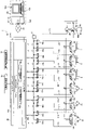
- FIG. 2 is a diagram showing a hydraulic drive system for a hydraulic excavator according to the first embodiment of the present invention.
- FIG. 3 is a functional block diagram of the controller according to the first embodiment of the invention.
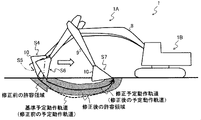
- FIG. 4 is a diagram showing a planned motion trajectory when an excavation work is performed and a working device that operates so that the toe of the bucket follows the planned motion trajectory.
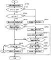
- FIG. 5 is a flowchart of automatic operation control executed by the controller, showing the flow from task information acquisition processing to control current output processing.
- FIG. 6 is a flowchart of automatic driving control executed by the controller, showing the flow from position/orientation information calculation processing to end signal output processing.
- FIG. 1 is a configuration diagram of a hydraulic excavator according to a first embodiment of the present invention.
- FIG. 2 is a diagram showing a hydraulic drive system for a hydraulic excavator according to the first embodiment of
- FIG. 7 is a functional block diagram of a controller according to the second embodiment of the invention.
- FIG. 8 is a diagram showing a planned motion trajectory when an excavation work is performed and a working device that operates so that the toe of the bucket follows the planned motion trajectory. Shows the motion trajectory.
- the work machine is a hydraulic excavator provided with a bucket 10 as a working tool (attachment) at the tip of the work device.
- an alphabet may be added to the end of the code (number), but the alphabet may be omitted to collectively describe the multiple components.
- an electromagnetic proportional valve 54 when there are two electromagnetic proportional valves 54a and 54b, they are collectively referred to as an electromagnetic proportional valve 54 in some cases.
- FIG. 1 is a configuration diagram of a hydraulic excavator 1 according to a first embodiment of the present invention.
- the hydraulic excavator 1 includes a vehicle body (machine body) 1B and an articulated front working device (hereinafter simply referred to as a working device) 1A attached to the vehicle body 1B.
- the vehicle body 1 ⁇ /b>B has a lower traveling body 11 that travels by left and right traveling hydraulic motors 3 a and 3 b and an upper revolving body 12 attached on the lower traveling body 11 that revolves with a revolving hydraulic motor 4 .
- the working device 1A includes a plurality of driven members (boom 8, arm 9 and bucket 10) and a plurality of hydraulic actuators that drive the driven members.
- the plurality of driven members are connected in series.
- a base end of the boom 8 is rotatably supported on the front part of the upper swing body 12 via a boom pin.
- An arm 9 is rotatably connected to the tip of the boom 8 via an arm pin.
- a bucket 10 as a working tool is rotatably connected to the tip of the arm 9 via a bucket pin.
- the boom 8 is driven by a hydraulic cylinder (hereinafter also referred to as a boom cylinder) 5, which is a hydraulic actuator.
- the arm 9 is driven by a hydraulic cylinder (hereinafter also referred to as an arm cylinder) 6, which is a hydraulic actuator.
- the bucket 10 is driven by a hydraulic cylinder (hereinafter also referred to as a bucket cylinder) 7, which is a hydraulic actuator.
- a boom angle sensor 30 is attached to the boom 8, an arm angle sensor 31 is attached to the arm 9, and a bucket angle sensor 32 is attached to the bucket link 13 so that the rotation angles of the boom 8, arm 9 and bucket 10 can be measured.
- a vehicle body tilt angle sensor 33 is attached to the upper revolving body 12 to detect the tilt angle of the upper revolving body 12 (vehicle body 1B) with respect to a reference plane (for example, a horizontal plane).
- FIG. 2 is a diagram showing a hydraulic drive system of the hydraulic excavator 1.
- the hydraulic drive system includes an engine 18, a main pump 2, a pilot pump 48, a plurality of flow control valves D1-D6, and a plurality of electromagnetic proportional valves 54a-59b.
- the engine 18 drives the main pump 2 and the pilot pump 48 .
- the pilot pump 48 is a fixed displacement hydraulic pump.
- the main pump 2 is a variable displacement hydraulic pump whose displacement is controlled by a regulator 2a, and discharges pressure oil to drive a plurality of hydraulic actuators (boom cylinder 5, arm cylinder 6, bucket cylinder 7, etc.).
- the regulator 2 a is driven by a control command from a controller 40 mounted on the upper revolving body 12 and controls the discharge flow rate of the main pump 2 .
- the pressure oil discharged from the main pump 2 is supplied to the boom cylinder 5 through the flow control valve D1, to the arm cylinder 6 through the flow control valve D2, to the bucket cylinder 7 through the flow control valve D3, and to the turning hydraulic motor 4 through the flow control valve D4. Then, it is supplied to the travel hydraulic motor 3a through the flow control valve D5 and to the travel hydraulic motor 3b through the flow control valve D6.
- the boom cylinder 5, the arm cylinder 6, and the bucket cylinder 7 are extended and contracted by the supplied pressure oil, so that the boom 8, the arm 9, and the bucket 10 are respectively rotated, and the posture of the working device 1A and the position of the bucket 10 are changed. .
- the supplied pressure oil rotates the turning hydraulic motor 4 , so that the upper turning body 12 turns with respect to the lower traveling body 11 .
- the traveling hydraulic motors 3a and 3b are rotated by the supplied pressure oil, so that the lower traveling body 11 travels.
- a lock valve 39 is provided in the pilot pump line 170 which is the discharge pipe of the pilot pump 48 .
- the downstream side of the lock valve 39 in the pilot pump line 170 is branched into a plurality of pilot lines C1-C12 and connected to electromagnetic proportional valves 54a-59b.
- the lock valve 39 of this embodiment is an electromagnetic switching valve, the solenoid of which is electrically connected to the position sensor of the gate lock lever 24 (see FIG. 1) arranged in the operator's cab 16 (see FIG. 1) of the upper rotating body 12. It is connected.
- the position of the gate lock lever 24 is detected by the position sensor, and a signal corresponding to the position of the gate lock lever 24 is input to the lock valve 39 from the position sensor.
- the lock valve 39 When the gate lock lever 24 is in the lock position, the lock valve 39 is closed to cut off the supply of hydraulic oil from the pilot pump 48 to the electromagnetic proportional valves 54a-59b.
- the lock valve 39 When the gate lock lever 24 is at the unlocked position, the lock valve 39 is opened and hydraulic oil is supplied from the pilot pump 48 to the electromagnetic proportional valves 54a-59b. In other words, when the pilot pump line 170 is blocked by the lock valve 39, the hydraulic actuators (3-7) are prohibited from operating.
- the flow control valves D1 to D6 control the flow of pressure oil supplied from the main pump 2 to the boom cylinder 5, arm cylinder 6, bucket cylinder 7, swing hydraulic motor 4, and travel hydraulic motors 3a and 3b.
- the flow control valve D1 is driven by pilot pressure input to the pressure receiving chambers E1 and E2 via pilot lines C1 and C2 provided with electromagnetic proportional valves 54a and 54b.
- the flow control valve D1 drives the boom cylinder 5 by controlling the supply direction and flow rate of the pressure oil from the main pump 2 .
- the flow control valve D2 is driven by pilot pressures input to pressure receiving chambers E3 and E4 through pilot lines C3 and C4 provided with electromagnetic proportional valves 55a and 55b.
- the flow control valve D2 drives the arm cylinder 6 by controlling the supply direction and flow rate of the pressure oil from the main pump 2 .
- the flow control valve D3 is driven by pilot pressures input to pressure receiving chambers E5 and E6 through pilot lines C5 and C6 provided with electromagnetic proportional valves 56a and 56b.
- the flow control valve D3 drives the bucket cylinder 7 by controlling the supply direction and flow rate of the pressure oil from the main pump 2 .
- the flow control valve D4 is driven by pilot pressures input to pressure receiving chambers E7 and E8 through pilot lines C7 and C8 provided with electromagnetic proportional valves 57a and 57b.
- the flow control valve D4 controls the supply direction and flow rate of pressure oil from the main pump 2 to drive the swing hydraulic motor 4 .
- the flow control valve D5 is driven by a pilot pressure input to pressure receiving chambers E9 and E10 through pilot lines C9 and C10 provided with electromagnetic proportional valves 58a and 58b.
- the flow control valve D5 controls the supply direction and flow rate of pressure oil from the main pump 2 to drive the travel hydraulic motor 3a.
- the flow control valve D6 is driven by pilot pressures input to the pressure receiving chambers E11 and E12 through pilot lines C11 and C12 provided with electromagnetic proportional valves 59a and 59b.
- the flow control valve D6 controls the supply direction and flow rate of pressure oil from the main pump 2 to drive the traveling hydraulic motor 3b.
- the electromagnetic proportional valves 54a-59b are controlled by control commands from the controller 40.
- the electromagnetic proportional valves 54 a to 59 b are pressure reducing valves that generate pilot pressure by reducing the primary pressure supplied from the pilot pump 48 to secondary pressure according to the control command (control current) from the controller 40 .
- the electromagnetic proportional valves 54a-59b output the generated pilot pressures to the pressure receiving chambers (E1-E12) of the flow control valves D1-D6.
- the posture detection device 50 includes a boom angle sensor 30 attached to the boom 8 (see FIG. 1), an arm angle sensor 31 attached to the arm 9 (see FIG. 1), and a bucket angle sensor 32 attached to the bucket 10 (see FIG. 1). and a vehicle body tilt angle sensor 33 (see FIG. 1) attached to the vehicle body 1B.
- These angle sensors (30, 31, 32, 33) acquire information representing angles as attitude information of the work implement 1A and output signals corresponding to the information. That is, the angle sensors (30, 31, 32, 33) function as attitude sensors that detect the attitude information of the working device 1A.
- the orientation detection device 50 includes, for example, an IMU (Inertial Measurement Unit) that acquires the angular velocity and acceleration of three orthogonal axes as angle sensors (30, 31, 32, 33), and an inertial measurement unit (IMU) based on the information acquired by the IMU. and an angle computing device for computing the boom angle, the arm angle, the bucket angle, and the vehicle body tilt angle. Potentiometers can also be used as the angle sensors (30, 31, 32).
- IMU Inertial Measurement Unit
- IMU inertial measurement unit
- Potentiometers can also be used as the angle sensors (30, 31, 32).
- the vehicle body position detection device 36 is attached to the upper revolving body 12 and detects position information and azimuth information of the upper revolving body 12 (body 1B).
- the vehicle body position detection device 36 includes a plurality of GNSS (Global Navigation Satellite System) antennas (hereinafter referred to as GNSS antennas) 36a (see FIG. 1) and GNSS antennas 36a.
- GNSS antennas Global Navigation Satellite System
- GNSS antennas Global Navigation Satellite System
- the communication device 51 is a device for communicating with the management system 180 .
- the controller 40 transmits information to the management system 180 via the communication device 51 and receives information from the management system 180 via the communication device 51 .
- the communication device 51 is a wireless communication device capable of wireless communication with the communication line 20, which is a wide area network, and has a communication interface including a communication antenna having a sensitive band of a predetermined frequency band.
- the communication line 20 is a mobile phone communication network (mobile communication network) developed by a mobile phone carrier or the like, the Internet, or the like.
- the communication device 51 uses a communication method such as Wi-Fi (registered trademark), ZigBee (registered trademark), or Bluetooth (registered trademark) to directly or indirectly exchange information with the management system 180. may be performed.
- the management system 180 is an external system that remotely manages (understands and monitors) the state of the hydraulic excavator 1 and is installed in a facility remote from the hydraulic excavator 1 .
- the management system 180 includes a management server 181 , a display device 184 and an input device 185 .
- the management server 181 includes a communication device 183 for communicating with the hydraulic excavator 1 via the communication line 20 and a storage device 182 such as a hard disk drive for storing information received from the hydraulic excavator 1 and the like.
- the management server 181 transmits information to the controller 40 via the communication device 183 and receives information from the controller 40 via the communication device 183 .
- the management server 181 displays information stored in the storage device 182 on a display device 184 such as a liquid crystal display device.
- the administrator can grasp the state of the hydraulic excavator 1 by operating the management server 181 with an input device 185 such as a keyboard and a mouse and displaying predetermined information of the hydraulic excavator 1 on the display device 184 .
- the administrator operates the input device 185 to input task information required for automatic control executed by the controller 40 of the hydraulic excavator 1 .
- the task information includes the type of automatic control and parameters for executing automatic control.
- Types of automatic control include, for example, excavation work, loading work, movement of vehicles, excavation and loading work, mobile excavation and loading work, and the like.
- An example of parameters for automatic control will be described.
- the parameters for automatically controlling the excavation work include the position coordinates of the 8 vertices on the geographic coordinate system for defining the rectangular parallelepiped excavation range.
- a parameter for automatic control of the loading operation is the position coordinates of the earth-discharging point on the geographic coordinate system.
- the management server 181 When a task information input operation is performed by the input device 185 , the management server 181 generates task information and transmits the task information to the hydraulic excavator 1 via the communication device 183 .
- the administrator wants the hydraulic excavator 1 to perform excavation and loading work
- the administrator selects excavation and loading work as the type of automatic control, and inputs the position coordinates of the eight vertices of the excavation area and the position coordinates of the earth discharging point. I do.
- the management server 181 generates and outputs task information in which automatic control of a group of works from the excavation operation to the loading operation (earth dumping operation) by the hydraulic excavator 1 is set as one task.
- the controller 40 of the hydraulic excavator 1 Upon receiving task information from the management system 180 , the controller 40 of the hydraulic excavator 1 generates operation plan information based on the task information and transmits the operation plan information to the management system 180 via the communication device 51 .
- the details of the process of generating operation plan information by the controller 40 of the hydraulic excavator 1 will be described later.
- the operation plan information generated by the controller 40 is input to the management system 180 .
- the management server 181 causes the display device 184 to display the input operation plan information.
- the administrator looks at the operation plan information displayed on the display screen of the display device 184, and performs an approval operation using the input device 185 when approving that the automatic control based on the operation plan information is to be executed.
- the management server 181 When an approval operation is performed by the input device 185 , the management server 181 generates an approval signal indicating that the operation plan information has been approved, and transmits the approval signal to the hydraulic excavator 1 via the communication device 183 .
- the administrator looks at the operation plan information displayed on the display screen of the display device 184, and if he/she does not approve that the automatic control based on the operation plan information is to be executed, performs a disapproval operation using the input device 185. .
- the management server 181 When a disapproval operation is performed by the input device 185 , the management server 181 generates a disapproval signal indicating disapproval of the operation plan information and transmits the disapproval signal to the hydraulic excavator 1 via the communication device 183 . That is, management system 180 outputs an approval signal or a non-approval signal according to the operation of input device 185 .
- the controller 40 of the hydraulic excavator 1 automatically controls the hydraulic actuators based on the motion plan information and the detection result of the posture detection device 50. Note that the controller 40 does not execute the automatic control unless the approval signal is input from the management system 180 .
- the controller 40 When the automatic control ends normally, the controller 40 generates a normal end signal and transmits the normal end signal to the management system 180 via the communication device 51 .
- the management server 181 Upon receiving the normal end signal, the management server 181 causes the display screen of the display device 184 to display an image such as a message indicating that the automatic control has ended normally. After confirming that the automatic control has ended normally, the administrator performs the task information input operation again.
- the management server 181 When the management server 181 receives information indicating that automatic control is being performed from the hydraulic excavator 1, the management server 181 displays a message indicating that automatic control is being performed on the display screen of the display device 184.
- the administrator wishes to temporarily suspend the automatic control, the administrator performs a suspension request operation using the input device 185 .
- the management server 181 When a pause request operation is performed by the input device 185 , the management server 181 generates a pause request signal and transmits the pause request signal to the hydraulic excavator 1 via the communication device 183 . After temporarily stopping the automatic control, the administrator performs a restart request operation using the input device 185 when he/she wants to resume the automatic control.
- the management server 181 When a restart request operation is performed by the input device 185 , the management server 181 generates a restart request signal and transmits the restart request signal to the hydraulic excavator 1 via the communication device 183 . After temporarily stopping the automatic control, the administrator uses the input device 185 to perform an intermediate termination request operation if he/she wishes to terminate the automatic control in the middle. When the input device 185 is operated to request an intermediate termination, the management server 181 generates an intermediate termination request signal and transmits the intermediate termination request signal to the hydraulic excavator 1 via the communication device 183 .
- controller 40 for realizing automatic control, and the flow of automatic operation control processing will be described in detail below.
- the controller 40 is a control device that automatically controls the hydraulic excavator 1 based on operation plan information.
- the controller 40 includes a processor 40a such as a CPU (Central Processing Unit), an MPU (Micro Processing Unit), a DSP (Digital Signal Processor), etc., a ROM (Read Only Memory), a flash memory, a non-volatile memory 40b such as a hard disk drive, a so-called RAM
- the computer comprises a volatile memory 40c called (random access memory), an input interface 40d, an output interface 40e, and other peripheral circuits.
- the controller 40 may be composed of one computer, or may be composed of a plurality of computers.
- the non-volatile memory 40b stores programs capable of executing various calculations.
- the nonvolatile memory 40b is a storage medium that can read a program that implements the functions of this embodiment.
- the processor 40a is a processing device that expands the program stored in the nonvolatile memory 40b into the volatile memory 40c and executes calculations, and is a processing device that reads data from the input interface 40d, the nonvolatile memory 40b, and the volatile memory 40c according to the program. A predetermined arithmetic processing is performed on the .
- the input interface 40d converts signals input from devices such as the posture detection device 50, the vehicle body position detection device 36, and the communication device 51 into data that can be calculated by the processor 40a.
- the output interface 40e generates an output signal according to the calculation result of the processor 40a, and outputs the signal to devices such as the electromagnetic proportional valves 54a to 59b, the communication device 51, and the like.
- FIG. 3 is a functional block diagram of the controller 40.
- the controller 40 includes a position/orientation calculation unit 43 , a proportional solenoid valve control unit 44 , an actuator control unit 81 , an operation planning unit 90 , an automatic operation control unit 91 , a track deviation determination unit 92 , and a time deviation determination unit 93 . , a first input section 100 , a second input section 101 , a third input section 102 , a first output section 110 and a second output section 111 .
- the illustration of the communication device 51 is omitted, and the transmission of information from the controller 40 to the management system 180 via the communication device 51 is simply referred to as output to the management system 180 .
- the fact that the controller 40 receives information from the management system 180 via the communication device 51 is simply referred to as inputting information from the management system 180 .
- Task information is input to the first input unit 100 from the management system 180 .
- An approval signal or a non-approval signal is input to the second input unit 101 from the management system 180 .
- a suspension request signal, a restart request signal, or an intermediate termination request signal is input from the management system 180 to the third input unit 102 .
- the position/posture calculation unit 43 calculates the position and azimuth angle of the upper swing structure 12 in the geographic coordinate system based on the detection result of the vehicle body position detection device 36, and based on the calculation result and the detection result of the posture detection device 50. The position and attitude of the working device 1A in the geographic coordinate system are calculated.
- the motion planning unit 90 generates motion planning information based on the task information acquired by the first input unit 100 .
- the motion plan information includes a planned motion trajectory that is a trajectory of a specific point of the work device 1A in the geographic coordinate system, time series information of the planned position of the specific point of the work device 1A in the geographic coordinate system, and time series of the planned attitude of the work device 1A. information and time-series information of the planned position of the vehicle body 1B in the geographic coordinate system.
- the specific point of the working device 1A is the center point of the toe of the bucket 10 in the left-right width direction.
- the time-series information of the scheduled position of the specific point of the working device 1A is the scheduled position coordinates of the specific point of the working device 1A at each scheduled time of a predetermined time interval from the start to the end of the task.
- the time-series information of the scheduled posture of the work device 1A is the boom angle, arm angle, and bucket angle at each scheduled time at predetermined time intervals from the start to the end of the task.
- the time-series information of the scheduled position of the vehicle body 1B is the scheduled position coordinates of the reference point of the vehicle body 1B at each scheduled time of a predetermined time interval from the start to the end of the task. Any point can be adopted as the reference point of the vehicle body 1B of the hydraulic excavator 1 .
- the reference point of the vehicle body 1B is the intersection of the lower surface of the undercarriage 11 and the turning center axis.
- the planned motion trajectory of the working device 1A may be composed of a plurality of position coordinates, or may be composed of functions.
- the first output unit 110 outputs the action planning information generated by the action planning unit 90 to the management system 180 .
- the automatic operation control unit 91 determines whether or not an approval signal has been input to the second input unit 101 .
- the motion planning information generated by the motion planning unit 90 and the hydraulic excavator 1 calculated by the position/posture calculation unit 43 (the positions and attitudes of the work device 1A, the upper revolving body 12 and the lower traveling body 11), the target value of the velocity of each hydraulic actuator (hereinafter referred to as target velocity) is calculated.
- the automatic motion control unit 91 controls the hydraulic cylinders (5, 6, 7) for driving the work device 1A based on the motion plan information and the position and orientation of the work device 1A.
- the automatic motion control unit 91 sets the target speed of the swing hydraulic motor 4 that drives the upper swing body 12 based on the operation plan information and the position and orientation of the upper swing body 12 .
- the automatic operation control unit 91 sets targets for the traveling hydraulic motors 3a and 3b that drive the lower traveling body 11 based on the operation plan information and the position and orientation of the lower traveling body 11. Calculate speed.
- the actuator control unit 81 controls the pressure receiving chambers E1 to E12 of the flow control valves D1 to D6 corresponding to the operating directions of the hydraulic actuators (3 to 7) based on the target speeds of the hydraulic actuators (3 to 7) calculated by the automatic operation control unit 91.
- a target value of the pilot pressure (hereinafter referred to as the target pilot pressure) to be applied to is calculated.
- the electromagnetic proportional valve control unit 44 calculates the control current value to be supplied to the solenoids of the respective electromagnetic proportional valves 54a to 59b, and controls the control current according to the calculation result. It is supplied to the solenoids of the electromagnetic proportional valves 54a-59b.
- FIG. 4 is a diagram showing the planned motion trajectory when the excavation work is performed, and the work device 1A that operates so that the toe of the bucket 10 follows the planned motion trajectory.
- a control current control command
- each hydraulic actuator operates, and the working device 1A moves along the planned operation trajectory.
- the toe of the bucket 10 may deviate from the planned motion trajectory or the moving speed of the toe of the bucket 10 may be slowed down due to the influence of the quality of the soil to be excavated.
- the track deviation determination unit 92 and the time deviation determination unit 93 shown in FIG. 3 monitor whether or not the actual operation of the work implement 1A deviates from the operation plan information.
- the trajectory deviation determination unit 92 determines whether or not the specific point of the work device 1A deviates from the planned operation trajectory at least during the execution of automatic control.
- the trajectory deviation determination unit 92 determines whether or not a specific point of the bucket 10 deviates from the planned motion trajectory based on the motion planning information generated by the motion planning unit 90 and the calculation result of the position/orientation calculation unit 43 . judge. That is, the track deviation determination unit 92 determines whether or not there is a positional deviation of the actual operation of the hydraulic excavator 1 with respect to the operation plan information.
- the shortest distance Dmin to the planned motion trajectory calculated by the planning unit 90 is calculated.
- the track deviation determination unit 92 determines whether or not the shortest distance Dmin is equal to or less than the distance threshold value D0.
- the track deviation determination unit 92 determines that the specific point P0 of the bucket 10 does not deviate from the planned operation track when the shortest distance Dmin is equal to or less than the distance threshold value D0.
- the track deviation determination unit 92 determines that the specific point P0 of the bucket 10 deviates from the planned operation track when the shortest distance Dmin is greater than the distance threshold D0.
- the distance threshold value D0 for example, a value on the order of several tens of millimeters to several hundreds of millimeters is predetermined and stored in the nonvolatile memory 40b. Note that the distance threshold value D0 may be determined according to the type of automatic control.
- the time deviation determination unit 93 shown in FIG. 3 determines whether or not the actual operation time of the work device 1A deviates from the scheduled operation time at least during execution of automatic control.
- the time deviation determination unit 93 determines whether the actual operation time of the hydraulic excavator 1 deviates from the scheduled operation time based on the operation plan information generated by the operation plan unit 90 and the calculation result of the position/orientation calculation unit 43. determine whether In other words, the time deviation determination unit 93 determines whether or not the actual operation of the hydraulic excavator 1 deviates from the operation plan information in terms of time.
- the time departure determination unit 93 determines the current position of the toe (specific point) P0 of the bucket 10 of the work implement 1A calculated by the position/orientation calculation unit 43. Locate a position on the near expected motion trajectory.
- the specified position is hereinafter referred to as a specified position P1.
- the time deviation determination unit 93 determines whether or not the time difference td is equal to or less than the time threshold t0. The time deviation determination unit 93 determines that the actual operation time of the hydraulic excavator 1 does not deviate from the scheduled operation time when the time difference td is equal to or less than the time threshold t0. The time deviation determination unit 93 determines that the actual operation time of the hydraulic excavator 1 deviates from the scheduled operation time when the time difference td is greater than the time threshold t0. For the time threshold t0, for example, a value on the order of several tens of seconds to several minutes is predetermined and stored in the nonvolatile memory 40b.
- the automatic motion control unit 91 terminates the automatic control. Further, the automatic motion control section 91 generates a first abnormal end signal indicating that the automatic control has been terminated due to the deviation of the specific point of the working device 1A from the planned motion trajectory.
- the second output section 111 outputs the first abnormal termination signal generated by the automatic operation control section 91 to the management system 180 .
- the automatic operation control unit 91 ends the automatic control. Furthermore, the automatic operation control section 91 generates a second abnormal end signal indicating that the automatic control has ended due to the fact that the actual operation time of the work device 1A has deviated from the scheduled operation time.
- the second output section 111 outputs the second abnormal termination signal generated by the automatic operation control section 91 to the management system 180 .
- the automatic motion control unit 91 calculates the position coordinates of the end of the planned motion trajectory (that is, the position coordinates of the specific point at the scheduled end time of the task) and the current specific point of the work device 1A calculated by the position/orientation calculation unit 43. It is determined whether or not the distance of the straight line connecting the position coordinates is equal to or less than the end determination threshold. When the distance of the straight line connecting the position coordinates of the end of the planned motion trajectory and the position coordinates of the specific point of the work implement 1A calculated by the position/orientation calculation unit 43 is equal to or less than the end determination threshold value, the automatic action control unit 91 , the automatic control is terminated assuming that the task execution completion condition is satisfied.
- the automatic operation control unit 91 generates a normal end signal indicating that the automatic control has ended normally.
- the automatic operation control unit 91 prevents the track deviation determination unit 92 from determining that the specific point of the work implement 1A is deviating from the planned motion trajectory, and the time deviation determination unit 93 prevents the work implement 1A from actually running. If the automatic control ends without determining that the operation time deviates from the scheduled operation time, a normal end signal is generated.
- the second output section 111 outputs the normal end signal generated by the automatic operation control section 91 to the management system 180 .
- the automatic operation control unit 91 determines whether or not a pause request signal has been input from the management system 180 to the third input unit 102 during execution of automatic control. If the automatic operation control unit 91 determines that a pause request signal has been input from the management system 180 to the third input unit 102 during execution of the automatic control, the automatic operation control unit 91 pauses the automatic control. Furthermore, the automatic operation control section 91 generates a pause signal indicating that the automatic control has been paused. The second output section 111 outputs the pause signal generated by the automatic operation control section 91 to the management system 180 .
- the automatic operation control unit 91 determines whether or not a restart request signal has been input from the management system 180 to the third input unit 102 during suspension of automatic control. If the automatic operation control unit 91 determines that a restart request signal has been input from the management system 180 to the third input unit 102 while the automatic control is suspended, the automatic control unit 91 restarts the automatic control.
- the automatic operation control unit 91 determines whether or not an intermediate termination request signal has been input from the management system 180 to the third input unit 102 during the suspension of automatic control. If the automatic operation control section 91 determines that an intermediate termination request signal has been input from the management system 180 to the third input section 102 during the suspension of the automatic control, the automatic control section 91 terminates the automatic control. Furthermore, the automatic operation control unit 91 generates an intermediate termination signal indicating that the automatic control has been terminated in the middle. The second output unit 111 outputs the halfway end signal generated by the automatic operation control unit 91 to the management system 180 .
- FIG. 5 shows the flow from task information acquisition processing to control current output processing in automatic driving control
- FIG. 6 shows the flow from position/orientation information calculation processing to end signal output processing in automatic driving control. is shown.
- step S110 the first input unit 100 acquires task information from the management system 180, and proceeds to step S120.
- step S120 the motion planning unit 90 generates motion planning information based on the task information acquired in step S110, and proceeds to step S130.
- step S130 the first output unit 110 outputs the operation plan information generated in step S120 to the management system 180, and proceeds to step S140.
- step S140 the second input unit 101 acquires a signal (hereinafter also referred to as a second input unit signal) from the management system 180, and proceeds to step S150.
- step S150 the automatic operation control section 91 determines whether or not the second input section signal acquired in step S140 is the approval signal.
- step S150 if the automatic operation control section 91 determines that the second input section signal is the approval signal, the process proceeds to step S160. If it is determined to be a non-approval signal), the process returns to step S110.
- step S150 If the determination in step S150 is negative, the automatic control by the controller 40 (processing after step S160) is not executed, and if the determination in step S150 is positive, the automatic control by the controller 40 (processing after step S160). is executed.
- step S ⁇ b>160 the automatic operation control unit 91 performs each operation based on the current position and orientation information (the current position and orientation of the hydraulic excavator 1 ) and the operation plan information, which are the calculation results of the position and orientation calculation unit 43 .
- the target speed of the hydraulic actuator is calculated, and the process proceeds to step S165.
- the current position and orientation information of the hydraulic excavator 1 is calculated in step S180, which will be described later, and stored in the nonvolatile memory 40b.
- step S165 the actuator control section 81 calculates target pilot pressures for the flow control valves D1 to D6 based on the target speeds calculated in step S160, and proceeds to step S170.
- step S170 the proportional solenoid valve control unit 44 calculates the control current value to be supplied to the solenoids of the proportional solenoid valves 54a to 59b based on the target pilot pressure calculated in step S170, and proceeds to step S175.
- step S175 the proportional electromagnetic valve control unit 44 supplies the control current corresponding to the calculation result in step S170 to the solenoids of the proportional electromagnetic valves 54a to 59b, and the process proceeds to step S180 (see FIG. 6).
- step S180 the position/orientation calculation unit 43 calculates the current position of the vehicle body 1B and the azimuth angle of the upper structure 12 in the geographical coordinate system based on the detection result of the vehicle body position detection device 36. do. Further, in step S180, the position/posture calculation unit 43 calculates the current position of the vehicle body 1B in the geographic coordinate system, the azimuth angle of the upper rotating body 12, the detection result of the posture detection device 50, and the hydraulic pressure stored in the nonvolatile memory 40b. Position and posture information of the hydraulic excavator 1 is calculated based on the dimensional information of each part of the excavator 1, and the process proceeds to step S190.
- the position and orientation information of the hydraulic excavator 1 includes the position and orientation of the work device 1A, the position and orientation of the upper revolving body 12, and the position and orientation of the lower traveling body 11. FIG.
- step S190 the track deviation determination unit 92 executes track deviation determination processing.
- the track deviation determination unit 92 determines the distance between the position of the specific point of the work implement 1A included in the calculation result in step S180 and the planned motion trajectory included in the motion plan information generated in step S120.
- the shortest distance Dmin is calculated.
- the track deviation determination unit 92 determines whether or not the shortest distance Dmin is equal to or less than the distance threshold value D0.
- step S190 when the track deviation determination unit 92 determines that the shortest distance Dmin is equal to or less than the distance threshold value D0, it determines that the specific point of the work device 1A does not deviate from the planned motion track, and proceeds to step S200.
- the track deviation determination unit 92 determines that the shortest distance Dmin is greater than the distance threshold value D0, it determines that the specific point of the work implement 1A deviates from the planned motion track, and proceeds to step S250.
- step S200 the time deviation determination unit 93 executes time deviation determination processing.
- the time deviation determination unit 93 identifies the position on the planned motion trajectory that is closest to the position of the specific point of the work implement 1A included in the calculation result in step S180.
- the time deviation determination unit 93 calculates the absolute value of the difference between the current time tc and the scheduled time te stored in association with the specific position included in the operation plan information as the differential time td. Furthermore, the time deviation determination unit 93 determines whether or not the time difference td is equal to or less than the time threshold t0.
- step S200 when the time difference determination unit 93 determines that the difference time td is equal to or less than the time threshold t0, it determines that the actual operation time of the hydraulic excavator 1 does not deviate from the scheduled operation time, and proceeds to step S210.
- step S200 when the time difference determination unit 93 determines that the time difference td is greater than the time threshold t0, it determines that the actual operation time of the hydraulic excavator 1 deviates from the scheduled operation time, and proceeds to step S250.
- step S210 the third input unit 102 acquires a signal (hereinafter also referred to as a third input unit signal) from the management system 180, and proceeds to step S220.
- step S220 the automatic operation control section 91 determines whether or not the third input section signal acquired in step S210 is a pause request signal.
- step S220 if the automatic operation control section 91 determines that the third input section signal is the pause request signal, the process proceeds to step S260, and if it determines that the third input section signal is not the pause request signal, the process proceeds to step S230.
- step S230 the automatic operation control unit 91 determines whether or not the task execution completion condition is satisfied. If it is determined in step S230 that the task execution completion condition is met, the process proceeds to step S240, and if it is determined that the task execution completion condition is not met, the process proceeds to step S160 (see FIG. 5).
- step S240 the second output unit 111 outputs a normal end signal to the management system 180 to end the automatic operation control.
- the 2nd output part 111 outputs an abnormal end signal to the management system 180, and complete
- step S250 the second output unit 111 outputs the first abnormal termination signal to the management system 180 if a negative determination is made in step S190, and outputs the second abnormal termination signal if a negative determination is made in step S200.
- a signal is output to management system 180 .
- step S260 the second output unit 111 outputs a pause signal to the management system 180, and proceeds to step S270.
- the third input unit 102 acquires a signal (third input unit signal) from the management system 180, and proceeds to step S280.
- step S280 the automatic operation control section 91 determines whether or not the third input section signal acquired in step S270 is a restart request signal. In step S280, if the automatic operation control section 91 determines that the third input signal is the restart request signal, the process proceeds to step S230, and if it determines that the third input signal is not the restart request signal, the process proceeds to step S290.
- step S290 the automatic operation control section 91 determines whether or not the third input section signal acquired in step S270 is the halfway termination request signal. In step S290, if the automatic operation control section 91 determines that the third input section signal is a premature termination request signal, it proceeds to step S300, and if it determines that the third input section signal is not a premature termination request signal, it returns to step S270.
- step S300 the second output unit 111 outputs an intermediate end signal to the management system 180 to end the automatic operation control.
- the management server 181 when the hydraulic excavator 1 is in the stopped state S1, the toe of the bucket 10 is positioned at the starting point of the excavation work.
- the management server 181 when the administrator performs an input operation for task information using the input device 185 , the management server 181 generates task information and transmits the task information to the hydraulic excavator 1 .
- the controller 40 of the hydraulic excavator 1 generates operation plan information based on the input task information (S110 ⁇ S120 in FIG. 5).
- the controller 40 transmits the generated operation plan information to the management system 180 (S130 in FIG. 5).
- the management server 181 causes the display device 184 to display the input operation plan information.
- the motion plan information output from the controller 40 to the management system 180 includes a planned motion trajectory that is a trajectory of specific points of the work device 1A, time-series information on the planned position of the work device 1A, and time-series information on the planned attitude of the work device 1A. , and time-series information of the expected position of the vehicle body 1B.
- the administrator can check the operation plan information before the hydraulic excavator 1 performs automatic control, and can determine whether or not to execute the automatic control based on the operation plan information.
- the management server 181 when the planned motion trajectory is input, the management server 181 generates a composite image in which the image of the line representing the planned motion trajectory and the terrain image are superimposed, and outputs it to the display device 184 .
- a composite image of the line image representing the planned motion trajectory and the terrain image is displayed.
- the administrator can confirm the operation plan information before the hydraulic excavator 1 performs automatic control.
- the administrator determines that the operation based on the operation plan information is not desired, the administrator performs a disapproval operation using the input device 185 .
- the management server 181 When a disapproval operation is performed by the input device 185 , the management server 181 generates a disapproval signal and transmits the disapproval signal to the hydraulic excavator 1 . In this way, the administrator can check the operation plan information in advance, so that it is possible to prevent the excavator 1 from performing operations not intended by the administrator.
- the display mode of the motion plan information is not limited to displaying on the display screen of the display device 184 a composite image of the line image representing the planned motion trajectory and the terrain image, and various display modes can be used.
- the management server 181 may cause the display screen of the display device 184 to display the time-series information of the planned position of the work device 1A included in the operation plan information in tabular form or graph form.
- the management server 181 causes the display screen of the display device 184 to display an animation of the hydraulic excavator 1 based on the time-series information of the planned posture of the work implement 1A included in the operation plan information by a well-known keyframe method or the like.
- the management server 181 when the automatic control includes movement of the vehicle, the management server 181 generates, for example, an image of a line representing the planned movement trajectory of the vehicle body 1B and a terrain image based on the time-series information of the planned position of the vehicle body 1B.
- the synthesized image is displayed on the display screen of the display device 184 .
- the administrator When the administrator performs a non-approval operation, the administrator performs a new task information input operation. As a result, the controller 40 generates new operation plan information based on the new task information and outputs it to the management system 180 (No in S140 ⁇ S150 in FIG. 5 ⁇ S110 ⁇ S120 ⁇ S130), so that a new operation can be performed.
- the planning information is displayed on the display screen of display device 184 .
- the administrator determines that there is no problem with the operation plan information
- the administrator performs approval operation using the input device 185 .
- the management server 181 When the approval operation is performed by the input device 185 , the management server 181 generates an approval signal and transmits the approval signal to the hydraulic excavator 1 .
- the controller 40 automatically controls the hydraulic excavator 1 based on the operation plan information (S140 in FIG. 5 ⁇ Yes in S150 ⁇ S160 ⁇ ... ⁇ S180 in FIG. 6 ⁇ Yes in S190 ⁇ S200 ⁇ Yes in S210 ⁇ No in S220 ⁇ No in S230).
- the controller 40 automatically controls the hydraulic actuators (5, 6, 7) so that the toe of the bucket 10 moves along the planned motion trajectory.
- the controller 40 determines whether the actual operation of the hydraulic excavator 1 deviates from the operation plan information. monitor what A hatched area in FIG. 4 is an area surrounded by an upper boundary where the planned motion trajectory is offset upward by the distance threshold value D0 and a lower boundary where the planned motion trajectory is offset downward by the distance threshold value D0 (hereinafter referred to as , referred to as the allowable region).
- an abnormal termination signal is output from the controller 40 to the management system 180 (S250 in FIG. 6).
- the display screen of the display device 184 displays an image such as a message indicating that the automatic control has stopped due to the deviation of the toe of the bucket 10 from the planned operation trajectory. Therefore, the administrator can know that the automatic control has stopped and the reason for it, which can be useful for creating the next task information.
- an abnormal termination signal is output from the controller 40 to the management system 180 (S250 in FIG. 6).
- the display screen of the display device 184 displays an image such as a message indicating that the automatic control has been stopped due to the deviation of the actual operation time of the work device 1A from the scheduled operation time. Therefore, the administrator can know that the automatic control has stopped and the reason for it, which can be useful for creating the next task information. For example, it is possible to prevent a work that is delayed from being repeatedly performed, thereby preventing the work from being delayed due to automatic control.
- the administrator wishes to temporarily stop the automatic control of the hydraulic excavator 1 for some reason while in the automatic control state S2, the administrator uses the input device 185 to perform a temporary stop request operation.
- the management server 181 When a pause request operation is performed by the input device 185 , the management server 181 generates a pause request signal and transmits the pause request signal to the hydraulic excavator 1 .
- the controller 40 stops the automatic control (S210 ⁇ Yes in S220 ⁇ No in S260 ⁇ S270 ⁇ No in S280 ⁇ No in S290 in FIG. 6).
- the controller 40 When suspending the automatic control, the controller 40 outputs a suspension signal to the management system 180 (S260 in FIG. 6). As a result, an image such as a message indicating that the automatic control has been suspended is displayed on the display screen of the display device 184 . Therefore, the administrator can confirm that the automatic control has been suspended.
- the administrator uses the input device 185 to perform a restart request operation.
- a restart request operation is performed by the input device 185
- the management server 181 generates a restart request signal and transmits the restart request signal to the hydraulic excavator 1 .
- the controller 40 restarts the automatic control (S270 in FIG. 6 ⁇ Yes in S280 ⁇ No in S230 ⁇ S160 in FIG. 5 ⁇ ).
- the administrator uses the input device 185 to perform a termination request operation.
- the management server 181 When the input device 185 is operated to request an intermediate termination, the management server 181 generates an intermediate termination request signal and transmits the intermediate termination request signal to the hydraulic excavator 1 .
- the controller 40 interrupts the automatic control (S270 in FIG. 6 ⁇ No in S280 ⁇ Yes in S290 ⁇ S300 ⁇ END).
- the controller 40 when ending the automatic control halfway, the controller 40 outputs a halfway end signal to the management system 180 (S300 in FIG. 6). As a result, on the display screen of the display device 184, an image such as a message indicating that the automatic control has ended halfway is displayed. Therefore, the administrator can confirm that the automatic control has ended halfway.
- Automatic control can be performed without determining that the specific point of the work device 1A deviates from the planned operation trajectory and without determining that the actual operation time of the work device 1A deviates from the planned operation time.
- a normal end signal is output from the controller 40 to the management system 180, and the hydraulic excavator 1 enters the stopped state S3 (Yes in S230 of FIG. 6 ⁇ S240 ⁇ END).
- a hydraulic excavator (work machine) 1 includes a work device 1A, a posture detection device 50 that detects posture information of the work device 1A, and hydraulic actuators (3a, 3b, 4, 5, 6, 7) and task information necessary for automatic control acquired from the management system (external system) 180 to generate motion plan information, and based on the motion plan information and the detection result of the posture detection device 50 and a controller (control device) 40 for automatically controlling the hydraulic actuators.
- Controller 40 outputs operation plan information to management system 180 .
- the controller 40 does not execute automatic control unless an approval signal indicating that the operation plan information has been approved is input from the management system 180, and if an approval signal is input from the management system 180, automatic control is performed. Execute control.
- the controller 40 presents the operation plan information of the hydraulic excavator 1 to the management system 180, and when an approval signal is obtained from the management system 180, performs automatic control according to the operation plan information.
- the controller 40 does not perform automatic control according to the operation plan information when the approval signal is not obtained from the management system 180 . Therefore, according to this embodiment, it is possible to prevent automatic control that is not intended by the administrator. That is, according to the present embodiment, it is possible to provide the hydraulic excavator 1 that can appropriately perform the operation intended by the administrator.
- the motion plan information includes a planned motion trajectory that is a trajectory of specific points of the working device 1A.
- the controller 40 determines whether or not the specific point of the work device 1A deviates from the planned motion trajectory during execution of automatic control. If the controller 40 determines that the specific point of the work implement 1A deviates from the planned motion trajectory during the execution of automatic control, it stops the automatic control and outputs an abnormal termination signal to the management system 180 .
- the controller 40 can present to the management system 180 that the automatic control has ended abnormally. Therefore, the administrator can recognize that the automatic control has ended abnormally.
- the controller 40 determines whether or not the actual operating time of the work device 1A deviates from the scheduled operating time during execution of automatic control. When the controller 40 determines that the actual operating time of the work implement 1A deviates from the scheduled operating time during execution of the automatic control, the controller 40 ends the automatic control and outputs an abnormal end signal to the management system 180.
- the automatic control is stopped, so it is possible to prevent the hydraulic excavator 1 from operating unintended by the administrator. For example, it is possible to prevent the operating time from becoming longer than the operating time intended by the administrator.
- the controller 40 can present to the management system 180 that the automatic control has ended abnormally. Therefore, the administrator can recognize that the automatic control has ended abnormally.
- the controller 40 does not determine that the specific point of the work device 1A deviates from the planned motion trajectory, and determines that the actual operation time of the work device 1A deviates from the planned operation time.
- a normal end signal is output to the management system 180 .
- the controller 40 can present to the management system 180 that the automatic control has ended normally. Therefore, the administrator can recognize that the next task information input operation can be performed.
- the controller 40 When the controller 40 receives a suspension request signal from the management system 180 during execution of automatic control, it suspends the automatic control and outputs a suspension signal to the management system 180 . As a result, the administrator can suspend the automatic control by outputting a suspension request signal from the management system 180 when the administrator wishes to temporarily suspend the automatic control for some reason. Also. The controller 40 can indicate to the management system 180 that automatic control has been suspended. Therefore, the administrator can recognize that the automatic control is suspended.
- the controller 40 When the controller 40 receives a restart request signal from the management system 180 while the automatic control is suspended, it restarts the automatic control.
- the controller 40 receives an intermediate termination request signal from the management system 180 while the automatic control is suspended, the controller 40 terminates the automatic control and outputs an intermediate termination signal to the management system 180 .
- the administrator can restart the automatic control by outputting a restart request signal from the management system 180 after suspending the automatic control.
- the management system 180 can output an intermediate termination request signal to terminate the automatic control in the middle.
- the controller 40 can indicate to the management system 180 that the automatic control was terminated prematurely. Therefore, the administrator can recognize that the automatic control has ended halfway.
- the controller 40 calculates the position of the vehicle body 1B based on the detection result of the vehicle body position detection device 36, and calculates the position and attitude of the working device 1A based on the calculation result and the detection result of the attitude detection device 50. .
- the position and attitude of the working device 1A in the geographic coordinate system can be calculated, so automatic control based on the operation plan information in the geographic coordinate system becomes possible.
- the controller 40 calculates both the position and orientation of the work device 1A, but it may calculate at least one of the position and orientation of the work device 1A.
- the controller 40 can perform automatic control based on at least one of the position and orientation of the work implement 1A and the operation plan information.
- the motion plan information output from the controller 40 to the management system 180 includes a planned motion trajectory that is a trajectory of specific points of the work device 1A, time-series information of a planned position of the work device 1A, and a planned attitude of the work device 1A. It includes time-series information and time-series information of the planned position of the vehicle body 1B. Therefore, the management system 180 displays on the display device 184 the planned motion trajectory, the time-series information of the planned position of the work implement 1A, the time-series information of the planned posture of the work implement 1A, and the time-series information of the planned position of the vehicle body 1B. can be made
- FIG. 7 is similar to FIG. 3 and is a functional block diagram of the controller 240 according to the second embodiment.
- FIG. 8 is a diagram similar to FIG. 4, and shows the planned motion trajectory when the excavation work is performed and the working device 1A in which the toe of the bucket 10 operates along the planned motion trajectory.
- FIG. 8 shows a reference planned motion trajectory and a corrected planned motion trajectory as planned motion trajectories.
- the action planning section 290 generates reference action plan information and corrected action plan information based on task information.
- the reference motion plan information corresponds to the motion plan information described in the first embodiment.
- the corrected action plan information is information obtained by correcting the reference action plan information, and is information different from the reference action plan information.
- the reference motion plan information includes a planned motion trajectory that is a trajectory of specific points of the work device 1A (hereinafter also referred to as a reference planned motion trajectory), time-series information of the planned position of the work device 1A, and time-series of the planned posture of the work device 1A. information, and time-series information of the planned position of the vehicle body 1B.
- the corrected motion plan information includes a planned motion trajectory that is a trajectory of specific points of the work device 1A (hereinafter also referred to as a corrected planned motion trajectory), time series information of the planned position of the work device 1A, and time series of the planned attitude of the work device 1A. information, and time-series information of the planned position of the vehicle body 1B.
- the corrected planned motion trajectory is a trajectory different from the reference planned motion trajectory, and is also used to indicate a possible range of correction of the planned motion trajectory during execution of automatic control, as will be described later.
- the automatic operation control unit 291 determines whether or not the correction condition is satisfied during the execution of automatic control.
- the automatic motion control unit 291 executes standard automatic control of the hydraulic actuator based on the standard motion plan information and the detection result of the posture detection device 50 when the correction condition is not satisfied.
- the automatic motion control unit 291 executes corrective automatic control of the hydraulic actuators based on the corrective action plan information and the detection result of the posture detection device 50 when the corrective condition is satisfied.
- the correction condition is predetermined to be met, for example, when the soil to be excavated is harder than expected.
- the correction condition can be, for example, a condition that is met when any one of the pressures of the hydraulic cylinders (5, 6, 7) remains equal to or higher than the pressure threshold for a predetermined time or longer.
- the controller 240 has a fourth input section 203 to which the detection result of the pressure detection device 60 is input.
- the pressure detection device 60 has a plurality of pressure sensors that detect the pressure in the bottom side oil chamber and the pressure in the rod side oil chamber of the hydraulic cylinders (5, 6, 7).
- the automatic operation control unit 291 is controlled when either the pressure in the bottom side oil chamber or the pressure in the rod side oil chamber of the hydraulic cylinders (5, 6, 7) continues to be equal to or higher than the pressure threshold for a predetermined time or longer. , it is determined that the correction condition is satisfied.
- the automatic operation control unit 291 is controlled when either the pressure in the bottom-side oil chamber or the pressure in the rod-side oil chamber of the hydraulic cylinders (5, 6, 7) is equal to or higher than the pressure threshold and has not continued for a predetermined time or longer. , it is determined that the correction condition is not satisfied.
- the trajectory deviation determination unit 292 determines whether or not the specific point of the work device 1A deviates from the reference planned operation trajectory at least during the execution of the reference automatic control. Further, the trajectory deviation determination unit 292 determines whether or not the specific point of the work implement 1A deviates from the planned correction motion trajectory at least during execution of the correction automatic control.
- the time deviation determination unit 293 determines whether or not the actual operation time of the work device 1A deviates from the scheduled operation time at least during execution of the reference automatic control and during execution of the correction automatic control.
- the automatic operation control unit 291 terminates the reference automatic control, Generate a first abnormal termination signal. Furthermore, the second output unit 111 outputs the first abnormal termination signal to the management system 180 .
- the automatic motion control unit 291 terminates the correction automatic control, Generate a first abnormal termination signal. Furthermore, the second output unit 111 outputs the first abnormal termination signal to the management system 180 .
- the automatic operation control unit 291 terminates the reference automatic control, Generate a second abnormal termination signal. Furthermore, the second output unit 111 outputs a second abnormal termination signal to the management system 180 .
- the automatic operation control unit 291 terminates the automatic correction control, Generate a second abnormal termination signal. Furthermore, the second output unit 111 outputs a second abnormal termination signal to the management system 180 .
- the automatic motion control unit 291 prevents the track deviation determination unit 292 from determining that the specific point of the work implement 1A deviates from the reference planned motion trajectory, and the time deviation determination unit 293 prevents the work implement 1A from actually moving. If the reference automatic control is ended without it being determined that the time has deviated from the scheduled operation time, a normal end signal is generated. Furthermore, the second output unit 111 outputs a normal end signal to the management system 180 .
- the automatic operation control unit 291 prevents the track deviation determination unit 292 from determining that the specific point of the work implement 1A deviates from the planned correction motion trajectory, and the time deviation determination unit 293 prevents the work implement 1A from actually moving. If the modified automatic control is terminated without it being determined that the time has deviated from the scheduled operation time, a normal termination signal is generated. Furthermore, the second output unit 111 outputs a normal end signal to the management system 180 .
- the toe of the bucket 10 is positioned at the starting point of the excavation work.
- the management server 181 when the administrator performs an input operation for task information using the input device 185 , the management server 181 generates task information and transmits the task information to the hydraulic excavator 1 .
- the controller 240 of the hydraulic excavator 1 generates operation plan information based on the input task information. Controller 240 transmits the generated operation plan information to management system 180 .
- the management server 181 causes the display device 184 to display the input operation plan information.
- the action plan information includes reference action plan information generated based on task information and corrected action plan information obtained by correcting the reference action plan information.
- the management server 181 causes the display screen of the display device 184 to display a range in which the planned motion trajectory may be corrected during execution of automatic control.
- the range in which the planned motion trajectory may be corrected during the execution of automatic control is, for example, the range surrounded by the reference planned motion trajectory and the corrected planned motion trajectory. Note that when a plurality of planned corrected motion trajectories are calculated, the range surrounded by the planned motion trajectory and the planned corrected motion trajectory farthest from the planned motion trajectory is the one where the planned motion trajectory is corrected during the execution of the automatic control. possible range.
- the administrator can confirm the operation plan information including the corrective operation plan information, and determine whether or not to execute the automatic control based on the operation plan information. can be done.
- the administrator determines that the operation based on the operation plan information is not desired, the administrator performs a disapproval operation using the input device 185 .
- the administrator determines that there is no problem with the operation plan information, the administrator performs approval operation using the input device 185 .
- the management server 181 When the approval operation is performed by the input device 185 , the management server 181 generates an approval signal and transmits the approval signal to the hydraulic excavator 1 .
- the controller 240 executes standard automatic control of the hydraulic excavator 1 based on the standard operation plan information.
- the controller 240 performs standard automatic control of each hydraulic actuator (5, 6, 7) so that the toe of the bucket 10 moves along the standard planned motion trajectory.
- a state S5 in which the standard automatic control is executed (hereinafter also referred to as a standard automatic control state)
- the controller 240 monitors whether or not the actual operation of the hydraulic excavator 1 deviates from the standard operation plan information.
- the reference automatic control state S5 if the actual operation of the hydraulic excavator 1 deviates from the reference operation plan information, the reference automatic control is stopped.
- the controller 240 performs correction automatic control of the hydraulic actuators (5, 6, 7) so that the toe of the bucket 10 moves along the planned correction motion trajectory. Run.
- the state transitions from the reference automatic control state S5 to the state in which the corrected automatic control is being executed hereinafter also referred to as the corrected automatic control state) S6, an allowable region is set according to the planned corrected motion trajectory.
- the controller 240 monitors whether the actual operation of the hydraulic excavator 1 deviates from the corrected operation plan information. In the corrective automatic control state S6, if the actual operation of the hydraulic excavator 1 deviates from the corrective operation plan information, the corrective automatic control is stopped.
- a normal end signal is output from the controller 240 to the management system 180, and the hydraulic excavator 1 enters the stopped state S7.
- the controller 240 presents motion plan information including a range in which the planned motion trajectory may be corrected, and automatically performs control according to the motion plan information when an approval signal is obtained from the management system 180. conduct.
- the controller 240 does not perform automatic control according to the operation plan information when the approval signal is not obtained from the management system 180 . Therefore, according to this embodiment, it is possible to prevent automatic control that is not intended by the administrator. That is, according to the second embodiment, like the first embodiment, it is possible to provide the hydraulic excavator 1 capable of appropriately executing the operation intended by the administrator.
- the motion trajectory is appropriately corrected according to the situation, it is possible to improve work efficiency.
- the soil to be excavated is harder than the manager assumes
- automatic control of the excavation work is executed in accordance with the planned correction operation trajectory assuming that the soil is hard. Therefore, when the soil quality of the excavation object is hard, the accuracy of the excavation work can be improved compared to the case where the excavation work is automatically controlled according to the reference planned motion trajectory, and the work can be prevented from being redone.
- work efficiency can be improved.
- the controller 240 determines that a specific point of the working device 1A deviates from the reference scheduled motion trajectory during execution of the reference automatic control, or the actual operation time of the working device 1A is the scheduled motion. If it is determined that there is a deviation from the time, it stops the reference automatic control and outputs an abnormal termination signal to the management system 180 . Similarly, the controller 240 determines that a specific point of the work implement 1A deviates from the planned corrected motion trajectory or the actual operation time of the work implement 1A deviates from the planned operation time during the execution of the correction automatic control. If so, it stops the automatic correction control and outputs an abnormal end signal to the management system 180 .
- the controller 240 does not determine that the specific point of the work device 1A deviates from the reference planned motion trajectory, and does not determine that the actual operation time of the work device 1A deviates from the scheduled operation time.
- a normal end signal is output to the management system 180 .
- the controller 240 determines that the actual operation time of the work device 1A deviates from the planned operation time without determining that the specific point of the work device 1A deviates from the corrected planned motion trajectory. If the correction automatic control is terminated without any changes, a normal termination signal is output to the management system 180 . Therefore, according to the second embodiment, the same effects as (2) to (4) described in the first embodiment can be obtained even when the corrected automatic control is performed in addition to the reference automatic control. be able to.
- the specific point of the work device 1A is the center point of the toe of the bucket 10 in the lateral width direction
- the left end point and the right end point of the toe of the bucket 10 may each be a specific point of the work device 1A.
- the position of the specific point on the bucket 10 may be changed according to the type of automatic control. For example, when the arm 9 is moved away from the vehicle body 1B to press the back surface of the bucket 10 against the inclined wall surface to harden the soil and level the ground under automatic control, the bucket 10 It is preferable that a point on the rear surface of the work device 1A is set as a specific point.
- the motion plan information output from the controllers 40 and 240 to the management system 180 includes the planned motion trajectory that is the trajectory of the specific points of the work device 1A, the time series information of the planned position of the work device 1A, the work device 1A. and the time series information of the planned position of the vehicle body 1B are included, but at least one of these pieces of information may be included in the motion plan information.
- the motion plan information includes the planned motion trajectory, which is the trajectory of specific points of the work implement 1A, and the time-series information of the planned position of the work implement 1A. , and time-series information of the intended posture of the work device 1A.
- the motion plan information may include time-series information of the planned position of the vehicle body 1B.
- the posture detection device 50 has angle sensors (30, 31, 32) as posture sensors for detecting posture information of the boom 8, the arm 9, and the bucket 10 has been described.
- the invention is not so limited.
- the posture detection device 50 may have a stroke sensor that detects the stroke amount of the hydraulic cylinders (5, 6, 7) as posture information instead of the angle sensors (30, 31, 32).
- the position/orientation calculator 43 calculates the boom angle, the arm angle, and the bucket angle based on the stroke amounts of the hydraulic cylinders (5, 6, 7).
- the controller 40, 240 determines whether or not there is a positional and temporal deviation of the actual operation of the hydraulic excavator 1 from the operation plan information, and stops the automatic control when there is a deviation.
- the controllers 40 and 240 may determine, for example, whether there is a positional or temporal deviation of the actual operation of the hydraulic excavator 1 from the operation plan information, and stop the automatic control if there is any deviation. Further, the deviation determination process of the actual operation of the excavator 1 with respect to the operation plan information and the automatic control stop process based on the determination result can be omitted.
- the working machine is the hydraulic excavator 1 having the bucket 10 in the above embodiment
- the present invention is not limited to this.
- the present invention may be applied to working machines having attachments other than buckets.
- the working machine is not limited to a crawler hydraulic excavator.
- the present invention can be applied to various working machines such as wheel-type hydraulic excavators and wheel loaders.
- the work machine is not limited to a movable work machine.
- the present invention can also be applied to a working machine in which a fixed machine body is provided with a revolving body, and the revolving body is provided with a multi-joint type working device.
- SYMBOLS 1... Hydraulic excavator (working machine), 1A... Working device, 1B... Vehicle body, 2... Main pump, 3a, 3b... Traveling hydraulic motor (hydraulic actuator), 4... Slewing hydraulic motor (hydraulic actuator), 5...
- Boom cylinder ( hydraulic actuator), 6 arm cylinder (hydraulic actuator), 7 bucket cylinder (hydraulic actuator), 8 boom, 9 arm, 10 bucket, 11 lower traveling body, 12 upper rotating body, 30, 31, 32, 33 Angle sensor (posture sensor) 36 Vehicle body position detection device 40 Controller (control device) 43 Position/posture calculation unit 44 Electromagnetic proportional valve control unit 50 Posture detection device 51 Communication Apparatus 60 Pressure detection device 81 Actuator control unit 90 Motion planning unit 91 Automatic motion control unit 92 Track deviation determination unit 93 Time deviation determination unit 100 First input unit 101 Second input unit 102 Third input unit 110 First output unit 111 Second output unit 180 Management system (external system) 181 Management server 182 Storage device 183 Communication device 184... Display device 185... Input device 203... Fourth input unit 240... Controller (control device) 290... Motion planning unit 291... Automatic motion control unit 292... Track deviation determination unit 293... Time deviation determination Department
Landscapes
- Engineering & Computer Science (AREA)
- Mining & Mineral Resources (AREA)
- Civil Engineering (AREA)
- General Engineering & Computer Science (AREA)
- Structural Engineering (AREA)
- Mechanical Engineering (AREA)
- Physics & Mathematics (AREA)
- General Physics & Mathematics (AREA)
- Life Sciences & Earth Sciences (AREA)
- General Life Sciences & Earth Sciences (AREA)
- Paleontology (AREA)
- Operation Control Of Excavators (AREA)
- Component Parts Of Construction Machinery (AREA)
Abstract
Description
-油圧ショベルの全体構成-
図1は、本発明の第1実施形態に係る油圧ショベル1の構成図である。図1に示すように、油圧ショベル1は、車体(機体)1Bと、車体1Bに取り付けられる多関節型のフロント作業装置(以下、単に作業装置と記す)1Aと、を備える。車体1Bは、左右の走行油圧モータ3a,3bにより走行する下部走行体11と、下部走行体11の上に取り付けられ、旋回油圧モータ4により旋回する上部旋回体12と、を有する。
コントローラ40は、動作計画情報に基づく油圧ショベル1の自動制御を実行する制御装置である。コントローラ40は、CPU(Central Processing Unit)、MPU(Micro Processing Unit)、DSP(Digital Signal Processor)等のプロセッサ40a、ROM(Read Only Memory)、フラッシュメモリ、ハードディスクドライブ等の不揮発性メモリ40b、所謂RAM(Random Access Memory)と呼ばれる揮発性メモリ40c、入力インタフェース40d、出力インタフェース40e及び、その他の周辺回路を備えたコンピュータで構成される。なお、コントローラ40は、1つのコンピュータで構成してもよいし、複数のコンピュータで構成してもよい。
図3は、コントローラ40の機能ブロック図である。コントローラ40は、位置姿勢演算部43と、電磁比例弁制御部44と、アクチュエータ制御部81と、動作計画部90と、自動動作制御部91と、軌道逸脱判定部92と、時間逸脱判定部93と、第1入力部100と、第2入力部101と、第3入力部102と、第1出力部110と、第2出力部111とを備えている。なお、図3では、通信装置51の図示は省略し、コントローラ40が、通信装置51を介して情報を管理システム180に送信することを、単に、管理システム180に出力するとも記す。また、コントローラ40が、管理システム180から通信装置51を介して情報を受信することを、単に、管理システム180から情報が入力されるとも記す。
図5及び図6を参照して、コントローラ40により実行される自動運転制御の一例について説明する。図5のフローチャートは、自動運転制御におけるタスク情報の取得処理から制御電流の出力処理までの流れを示し、図6のフローチャートは、自動運転制御における位置姿勢情報演算処理から終了信号出力処理までの流れを示している。
本実施形態に係る油圧ショベル1の主な動作について説明する。以下では、自動制御の種類が掘削作業である場合を例に油圧ショベル1の主な動作について説明する。
図7及び図8を参照して、本発明の第2実施形態に係る油圧ショベル1を説明する。なお、図中、第1実施形態と同一または相当部分には、同一の参照番号を付し、相違点を主に説明する。図7は、図3と同様の図であり、第2実施形態に係るコントローラ240の機能ブロック図である。図8は、図4と同様の図であり、掘削作業が行われたときの予定動作軌道と、バケット10の爪先が予定動作軌道に沿うように動作する作業装置1Aについて示す図である。図8では、予定動作軌道としての基準予定動作軌道及び修正予定動作軌道を示している。
図7に示すように、動作計画部290は、タスク情報に基づいて、基準動作計画情報及び修正動作計画情報を生成する。基準動作計画情報は、第1実施形態で説明した動作計画情報に相当する。修正動作計画情報は、基準動作計画情報を修正した情報であり、基準動作計画情報とは異なる情報である。
本実施形態に係る油圧ショベル1の主な動作について説明する。以下では、自動制御の種類が掘削作業である場合を例に油圧ショベル1の主な動作について説明する。
上記実施形態では、作業装置1Aの特定点が、バケット10の爪先における左右幅方向の中心点である例について説明したが、本発明はこれに限定されない。バケット10の爪先の左端点及び右端点が、それぞれ作業装置1Aの特定点であってもよい。また、バケット10の特定点の位置は、自動制御の種類に応じて変更してもよい。例えば、アーム9が車体1Bから離れるようにアーム9を動作させることにより、傾斜した壁面に対してバケット10の背面を押し付け、土砂を固めて整地する作業を自動制御で行う場合には、バケット10の背面上の点を作業装置1Aの特定点とすることが好ましい。
上記実施形態では、油圧ショベル1が車体位置検出装置36を備えている例について説明したが、本発明はこれに限定されない。油圧ショベル1は、車体位置検出装置36を備えていなくてもよい。この場合、動作計画情報及び油圧ショベル1の各部の位置情報は、ショベル基準座標系で定義すればよい。
上記実施形態では、コントローラ40,240から管理システム180に出力される動作計画情報に、作業装置1Aの特定点の軌道である予定動作軌道、作業装置1Aの予定位置の時系列情報、作業装置1Aの予定姿勢の時系列情報、及び、車体1Bの予定位置の時系列情報が含まれている例について説明したが、これらの情報の少なくともいずれか1つを動作計画情報に含むようにしてもよい。例えば、自動制御の種類が、車両の移動を伴わない作業である場合には、動作計画情報は、作業装置1Aの特定点の軌道である予定動作軌道、作業装置1Aの予定位置の時系列情報、及び、作業装置1Aの予定姿勢の時系列情報の少なくともいずれか1つを含んでいればよい。また、自動制御の種類が、車両の移動である場合には、動作計画情報は、車体1Bの予定位置の時系列情報を含んでいればよい。
上記実施形態では、姿勢検出装置50が、ブーム8、アーム9及びバケット10の姿勢情報を検出する姿勢センサとしての角度センサ(30,31,32)を有している例について説明したが、本発明はこれに限定されない。姿勢検出装置50は、角度センサ(30,31,32)に代えて、油圧シリンダ(5,6,7)のストローク量を姿勢情報として検出するストロークセンサを有していてもよい。位置姿勢演算部43は、油圧シリンダ(5,6,7)のストローク量に基づいて、ブーム角、アーム角及びバケット角を演算する。
上記実施形態では、コントローラ40,240が、動作計画情報に対する実際の油圧ショベル1の動作の位置的及び時間的な逸脱の有無を判定し、逸脱が有る場合に自動制御を停止する例について説明したが、本発明はこれに限定されない。コントローラ40,240は、例えば、動作計画情報に対する実際の油圧ショベル1の動作の位置的または時間的な逸脱の有無を判定し、逸脱が有る場合に自動制御を停止するようにしてもよい。また、動作計画情報に対する実際の油圧ショベル1の動作の逸脱判定処理、及び、その判定結果に基づく自動制御の停止処理は、省略することもできる。
上記実施形態では、作業機械がバケット10を備える油圧ショベル1である例について説明したが、本発明はこれに限定されない。例えば、バケット以外のアタッチメントを備える作業機械に本発明を適用しても構わない。また、作業機械は、クローラ式の油圧ショベルである場合に限定されることもない。例えば、ホイール式の油圧ショベル、ホイールローダ等の種々の作業機械に本発明を適用することができる。また、作業機械は、移動可能な作業機械に限定されることもない。例えば、固定式の機体に旋回体が設けられ、旋回体に多関節型の作業装置が設けられた作業機械に、本発明を適用することもできる。
Claims (9)
- 作業装置と、
前記作業装置の姿勢情報を検出する姿勢検出装置と、
前記作業装置を駆動する油圧アクチュエータと、
外部システムから取得した自動制御に必要なタスク情報に基づいて動作計画情報を生成し、前記動作計画情報及び前記姿勢検出装置の検出結果に基づいて前記油圧アクチュエータの自動制御を実行する制御装置と、を備える作業機械において、
前記制御装置は、
前記動作計画情報を前記外部システムに出力し、
前記外部システムから前記動作計画情報を承認したことを表す承認信号が入力されていない場合には、前記自動制御を実行せず、
前記外部システムから前記承認信号が入力された場合には、前記自動制御を実行する
ことを特徴とする作業機械。 - 請求項1に記載の作業機械において、
前記作業装置が取り付けられる車体の位置情報を検出する車体位置検出装置をさらに備え、
前記制御装置は、前記車体位置検出装置の検出結果に基づいて前記車体の位置を演算し、その演算結果と前記姿勢検出装置の検出結果に基づいて前記作業装置の位置及び姿勢の少なくともいずれかを演算する
ことを特徴とする作業機械。 - 請求項2に記載の作業機械において、
前記制御装置から前記外部システムに出力される前記動作計画情報は、前記作業装置の特定点の軌道である予定動作軌道、前記作業装置の予定位置の時系列情報、前記作業装置の予定姿勢の時系列情報、及び、前記車体の予定位置の時系列情報の少なくともいずれか1つを含む
ことを特徴とする作業機械。 - 請求項1に記載の作業機械において、
前記動作計画情報は、前記作業装置の特定点の軌道である予定動作軌道を含み、
前記制御装置は、
前記自動制御の実行中に、前記作業装置の特定点が前記予定動作軌道から逸脱しているか否かを判定し、
前記自動制御の実行中に、前記作業装置の特定点が前記予定動作軌道から逸脱していると判定すると、前記自動制御を終了し、前記外部システムに異常終了信号を出力し、
前記作業装置の特定点が前記予定動作軌道から逸脱していると判定することなく、前記自動制御を終了した場合には、前記外部システムに正常終了信号を出力する
ことを特徴とする作業機械。 - 請求項1に記載の作業機械において、
前記制御装置は、
前記自動制御の実行中に、前記作業装置の実動作時間が予定動作時間から逸脱しているか否かを判定し、
前記自動制御の実行中に、前記作業装置の実動作時間が前記予定動作時間から逸脱していると判定すると、前記自動制御を終了し、前記外部システムに異常終了信号を出力し、
前記作業装置の実動作時間が前記予定動作時間から逸脱していると判定することなく、前記自動制御を終了した場合には、前記外部システムに正常終了信号を出力する
ことを特徴とする作業機械。 - 請求項1に記載の作業機械において、
前記制御装置は、前記自動制御の実行中に、前記外部システムから一時停止要求信号が入力されると、前記自動制御を一時停止し、前記外部システムに一時停止信号を出力する
ことを特徴とする作業機械。 - 請求項6に記載の作業機械において、
前記制御装置は、
前記自動制御の一時停止中に、前記外部システムから再開要求信号が入力されると、前記自動制御を再開し、
前記自動制御の一時停止中に、前記外部システムから途中終了要求信号が入力されると、前記自動制御を終了し、前記外部システムに途中終了信号を出力する
ことを特徴とする作業機械。 - 請求項1に記載の作業機械において、
前記動作計画情報は、前記タスク情報に基づいて生成された基準動作計画情報と、前記基準動作計画情報を修正した修正動作計画情報とを含み、
前記制御装置は、
修正条件が成立したか否かを判定し、
前記修正条件が成立していない場合には、前記基準動作計画情報及び前記姿勢検出装置の検出結果に基づいて前記油圧アクチュエータの基準自動制御を実行し、
前記修正条件が成立した場合には、前記修正動作計画情報及び前記姿勢検出装置の検出結果に基づいて前記油圧アクチュエータの修正自動制御を実行する
ことを特徴とする作業機械。 - 請求項8に記載の作業機械において、
前記作業装置が取り付けられる車体を備え、
前記基準動作計画情報は、前記作業装置の特定点の軌道である予定動作軌道、前記作業装置の予定位置の時系列情報、前記作業装置の予定姿勢の時系列情報、及び、前記車体の予定位置の時系列情報の少なくともいずれか1つを含み、
前記修正動作計画情報は、前記自動制御の実行中に前記予定動作軌道を修正する可能性のある範囲、前記作業装置の予定位置の時系列情報、前記作業装置の予定姿勢の時系列情報、及び、前記車体の予定位置の時系列情報の少なくともいずれか1つを含む
ことを特徴とする作業機械。
Priority Applications (5)
| Application Number | Priority Date | Filing Date | Title |
|---|---|---|---|
| JP2023506938A JP7332835B2 (ja) | 2021-03-19 | 2022-02-28 | 作業機械 |
| EP22771084.5A EP4310262A4 (en) | 2021-03-19 | 2022-02-28 | CONSTRUCTION EQUIPMENT |
| KR1020237007402A KR102782640B1 (ko) | 2021-03-19 | 2022-02-28 | 작업 기계 |
| CN202280005848.6A CN116096972B (zh) | 2021-03-19 | 2022-02-28 | 作业机械 |
| US18/024,119 US20230304261A1 (en) | 2021-03-19 | 2022-02-28 | Work machine |
Applications Claiming Priority (2)
| Application Number | Priority Date | Filing Date | Title |
|---|---|---|---|
| JP2021046321 | 2021-03-19 | ||
| JP2021-046321 | 2021-03-19 |
Publications (1)
| Publication Number | Publication Date |
|---|---|
| WO2022196330A1 true WO2022196330A1 (ja) | 2022-09-22 |
Family
ID=83321464
Family Applications (1)
| Application Number | Title | Priority Date | Filing Date |
|---|---|---|---|
| PCT/JP2022/008431 Ceased WO2022196330A1 (ja) | 2021-03-19 | 2022-02-28 | 作業機械 |
Country Status (6)
| Country | Link |
|---|---|
| US (1) | US20230304261A1 (ja) |
| EP (1) | EP4310262A4 (ja) |
| JP (1) | JP7332835B2 (ja) |
| KR (1) | KR102782640B1 (ja) |
| CN (1) | CN116096972B (ja) |
| WO (1) | WO2022196330A1 (ja) |
Cited By (1)
| Publication number | Priority date | Publication date | Assignee | Title |
|---|---|---|---|---|
| WO2025018223A1 (ja) * | 2023-07-19 | 2025-01-23 | 株式会社安藤・間 | 自動運転情報算出システム、及び自動運転情報算出方法 |
Families Citing this family (2)
| Publication number | Priority date | Publication date | Assignee | Title |
|---|---|---|---|---|
| JP7009600B1 (ja) * | 2020-12-07 | 2022-01-25 | 日立建機株式会社 | 作業機械 |
| KR20220142082A (ko) * | 2021-04-14 | 2022-10-21 | 현대두산인프라코어(주) | 건설기계의 작업 계획 작성 방법 및 작성 시스템 |
Citations (6)
| Publication number | Priority date | Publication date | Assignee | Title |
|---|---|---|---|---|
| JPH101968A (ja) * | 1996-06-18 | 1998-01-06 | Hitachi Constr Mach Co Ltd | 油圧建設機械の自動軌跡制御装置 |
| JP2000136549A (ja) | 1998-10-09 | 2000-05-16 | Carnegie Mellon Univ | 自律掘削及びトラック載荷システム |
| WO2019181872A1 (ja) * | 2018-03-20 | 2019-09-26 | 住友重機械工業株式会社 | ショベル |
| JP2020002709A (ja) * | 2018-06-29 | 2020-01-09 | 日立建機株式会社 | 作業機械 |
| JP2020020153A (ja) | 2018-07-31 | 2020-02-06 | 株式会社小松製作所 | 作業機械 |
| JP2020180452A (ja) * | 2019-04-24 | 2020-11-05 | 株式会社小松製作所 | 作業機械を制御するためのシステムおよび方法 |
Family Cites Families (13)
| Publication number | Priority date | Publication date | Assignee | Title |
|---|---|---|---|---|
| KR20120004132A (ko) * | 2010-07-06 | 2012-01-12 | 전자부품연구원 | 굴삭기 자동화 시스템 및 그 통합 관리 방법 |
| JP6232494B2 (ja) * | 2014-04-23 | 2017-11-15 | 株式会社日立製作所 | 掘削装置 |
| US10214877B2 (en) * | 2015-01-28 | 2019-02-26 | Hitachi, Ltd. | Operation system of working machine |
| JP6589713B2 (ja) | 2016-03-24 | 2019-10-16 | トヨタ自動車株式会社 | 自動運転車両を用いたタクシーサービスシステム |
| JP6878317B2 (ja) * | 2017-01-31 | 2021-05-26 | 株式会社小松製作所 | 作業車両の制御システム、及び作業機の軌跡設定方法 |
| WO2019151335A1 (ja) * | 2018-01-30 | 2019-08-08 | 住友建機株式会社 | ショベル及びショベルの管理システム |
| CN111919003A (zh) * | 2018-03-26 | 2020-11-10 | 住友建机株式会社 | 挖土机 |
| JP7307051B2 (ja) * | 2018-03-31 | 2023-07-11 | 住友建機株式会社 | ショベル |
| JP7014018B2 (ja) * | 2018-04-06 | 2022-02-01 | 株式会社デンソー | 管制装置 |
| CN108797669B (zh) * | 2018-06-20 | 2020-12-22 | 清华大学 | 一种自主3d挖掘施工机器人 |
| JP7088792B2 (ja) * | 2018-09-12 | 2022-06-21 | 株式会社小松製作所 | 作業機械、制御装置、および制御方法 |
| JP7149205B2 (ja) * | 2019-03-05 | 2022-10-06 | 日立建機株式会社 | 自動運転作業機械 |
| US11650595B2 (en) * | 2019-07-30 | 2023-05-16 | Caterpillar Inc. | Worksite plan execution |
-
2022
- 2022-02-28 KR KR1020237007402A patent/KR102782640B1/ko active Active
- 2022-02-28 EP EP22771084.5A patent/EP4310262A4/en active Pending
- 2022-02-28 JP JP2023506938A patent/JP7332835B2/ja active Active
- 2022-02-28 US US18/024,119 patent/US20230304261A1/en active Pending
- 2022-02-28 CN CN202280005848.6A patent/CN116096972B/zh active Active
- 2022-02-28 WO PCT/JP2022/008431 patent/WO2022196330A1/ja not_active Ceased
Patent Citations (6)
| Publication number | Priority date | Publication date | Assignee | Title |
|---|---|---|---|---|
| JPH101968A (ja) * | 1996-06-18 | 1998-01-06 | Hitachi Constr Mach Co Ltd | 油圧建設機械の自動軌跡制御装置 |
| JP2000136549A (ja) | 1998-10-09 | 2000-05-16 | Carnegie Mellon Univ | 自律掘削及びトラック載荷システム |
| WO2019181872A1 (ja) * | 2018-03-20 | 2019-09-26 | 住友重機械工業株式会社 | ショベル |
| JP2020002709A (ja) * | 2018-06-29 | 2020-01-09 | 日立建機株式会社 | 作業機械 |
| JP2020020153A (ja) | 2018-07-31 | 2020-02-06 | 株式会社小松製作所 | 作業機械 |
| JP2020180452A (ja) * | 2019-04-24 | 2020-11-05 | 株式会社小松製作所 | 作業機械を制御するためのシステムおよび方法 |
Non-Patent Citations (1)
| Title |
|---|
| See also references of EP4310262A4 |
Cited By (1)
| Publication number | Priority date | Publication date | Assignee | Title |
|---|---|---|---|---|
| WO2025018223A1 (ja) * | 2023-07-19 | 2025-01-23 | 株式会社安藤・間 | 自動運転情報算出システム、及び自動運転情報算出方法 |
Also Published As
| Publication number | Publication date |
|---|---|
| KR102782640B1 (ko) | 2025-03-19 |
| KR20230044508A (ko) | 2023-04-04 |
| EP4310262A1 (en) | 2024-01-24 |
| JPWO2022196330A1 (ja) | 2022-09-22 |
| US20230304261A1 (en) | 2023-09-28 |
| JP7332835B2 (ja) | 2023-08-23 |
| CN116096972B (zh) | 2026-03-06 |
| EP4310262A4 (en) | 2025-04-23 |
| CN116096972A (zh) | 2023-05-09 |
Similar Documents
| Publication | Publication Date | Title |
|---|---|---|
| CN109115213B (zh) | 用于利用传感器融合来确定机器状态的系统和方法 | |
| CN109101032B (zh) | 用于利用传感器融合来控制机器姿态的系统和方法 | |
| CN109099033B (zh) | 利用传感器融合反馈在机器中控制流体压力的方法和系统 | |
| JP7332835B2 (ja) | 作業機械 | |
| CN111771027B (zh) | 作业机械 | |
| US8577564B2 (en) | System and method for controlling movement along a three dimensional path | |
| US11585071B2 (en) | Hystat swing motion actuation, monitoring, and control system | |
| CN112639212B (zh) | 作业机械 | |
| CN112424430A (zh) | 控制装置、装载机械及控制方法 | |
| KR20190112073A (ko) | 작업 기계 | |
| US20220010520A1 (en) | Shovel | |
| US12012716B2 (en) | Work machine | |
| US12416133B2 (en) | Swing motion variable control system | |
| WO2022168447A1 (ja) | 自動作業システム | |
| AU2023202409A1 (en) | Stability system for an articulated machine | |
| JP2025158275A (ja) | 自動運転制御装置、作業機械、自動運転制御システム、自動運転制御方法および自動運転制御プログラム | |
| JP2025157901A (ja) | 作業機械 | |
| WO2025164160A1 (ja) | 作業機械制御装置、作業機械、作業機械用外部装置、作業機械システムおよび位置補正方法 | |
| JP2022067548A (ja) | 作業機械 |
Legal Events
| Date | Code | Title | Description |
|---|---|---|---|
| 121 | Ep: the epo has been informed by wipo that ep was designated in this application |
Ref document number: 22771084 Country of ref document: EP Kind code of ref document: A1 |
|
| ENP | Entry into the national phase |
Ref document number: 2023506938 Country of ref document: JP Kind code of ref document: A |
|
| ENP | Entry into the national phase |
Ref document number: 20237007402 Country of ref document: KR Kind code of ref document: A |
|
| WWE | Wipo information: entry into national phase |
Ref document number: 2022771084 Country of ref document: EP |
|
| NENP | Non-entry into the national phase |
Ref country code: DE |
|
| ENP | Entry into the national phase |
Ref document number: 2022771084 Country of ref document: EP Effective date: 20231019 |