WO2022201457A1 - Démultiplexeur - Google Patents
Démultiplexeur Download PDFInfo
- Publication number
- WO2022201457A1 WO2022201457A1 PCT/JP2021/012654 JP2021012654W WO2022201457A1 WO 2022201457 A1 WO2022201457 A1 WO 2022201457A1 JP 2021012654 W JP2021012654 W JP 2021012654W WO 2022201457 A1 WO2022201457 A1 WO 2022201457A1
- Authority
- WO
- WIPO (PCT)
- Prior art keywords
- terminal
- orthogonal
- cross
- sectional shape
- common terminal
- Prior art date
- Legal status (The legal status is an assumption and is not a legal conclusion. Google has not performed a legal analysis and makes no representation as to the accuracy of the status listed.)
- Ceased
Links
Images




Classifications
-
- H—ELECTRICITY
- H01—ELECTRIC ELEMENTS
- H01P—WAVEGUIDES; RESONATORS, LINES, OR OTHER DEVICES OF THE WAVEGUIDE TYPE
- H01P1/00—Auxiliary devices
- H01P1/16—Auxiliary devices for mode selection, e.g. mode suppression or mode promotion; for mode conversion
Definitions
- the present invention relates to polarization/demultiplexers mainly used in the VHF band, UHF band, microwave band and millimeter wave band.
- a circuit for separating two orthogonal linearly polarized waves in two frequency bands is useful in satellite communication feed circuits.
- this polarization/demultiplexer one having one coaxial terminal and one orthogonal terminal is known.
- a common terminal that transmits two orthogonal linearly polarized waves of two frequency bands is provided, a coaxial terminal is provided on the opposite surface of the common terminal, and an orthogonal terminal is provided in a direction perpendicular to the coaxial terminal.
- the coaxial terminal is arranged on the same central axis as the common terminal, and the square cross-sectional shape of the common terminal has a transformation part where the square cross-sectional shape of the common terminal transforms into the rectangular cross-sectional shape of the coaxial terminal.
- the structure is symmetrical in the vicinity of the coaxial terminal.
- a transforming portion is provided outside the cross-section of the common terminal in which the shape of the short-circuit surface transforms into the rectangular cross-sectional shape of the orthogonal terminal.
- a polarization/demultiplexer has a common terminal consisting of a circular or square waveguide, a coaxial terminal consisting of a rectangular waveguide, and an orthogonal terminal consisting of a rectangular waveguide.
- the orthogonal terminal is arranged in the same direction as the common terminal and facing the common terminal, the orthogonal terminal is arranged in the direction orthogonal to the common terminal, the common terminal transmits two linearly polarized waves, and one of the two linearly polarized waves , one linearly polarized wave is transmitted through the coaxial terminal and the other linearly polarized wave is transmitted through the orthogonal terminal, and between the common terminal and the coaxial terminal is the cross-sectional shape of the common terminal
- the coaxial terminal has a first transforming portion in which the cross-sectional shape of the coaxial terminal changes stepwise, and the coaxial terminal is arranged offset from the central axis of the common terminal, and has an orthogonal terminal and a short-circuit surface facing the orthogonal terminal. Between them, there is
- FIG. 1 is a perspective view of a polarization/demultiplexer according to Embodiment 1;
- FIG. 2 is a top view of the polarization/demultiplexer according to Embodiment 1;
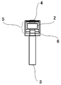
- FIG. 1 is a cross-sectional view of a polarization/demultiplexer according to Embodiment 1;
- FIG. 4 is a graph showing the reflection characteristics of orthogonal terminals in the low frequency band;
- FIG. 4 is a graph showing reflection characteristics of a coaxial terminal in a high frequency band; It is a figure which shows an example (straight line) of a metamorphic part. It is a figure which shows an example (circular arc shape) of a metamorphic part.
- FIG. 4 is a top view showing an example (straight line) of a transforming portion of a coaxial terminal or orthogonal terminal;
- FIG. 4 is a cross-sectional view showing an example (straight line) of a transforming portion of a coaxial terminal or orthogonal terminal;
- FIG. 4 is a top view showing an example (arcuate shape) of a metamorphic portion of a coaxial terminal or orthogonal terminal;
- FIG. 4 is a cross-sectional view showing an example (arcuate shape) of a metamorphic portion of a coaxial terminal or orthogonal terminal;
- FIG. 10 is a top view showing an example of a transforming section of a coaxial terminal or orthogonal terminal (a combination of a straight line and a stepped shape);
- FIG. 10 is a diagram showing a polarization/demultiplexer with a circular common terminal;
- FIG. 1 is a perspective view for explaining the configuration of a polarization/demultiplexer according to this embodiment.
- 1 is a common terminal
- 2 is a coaxial terminal
- 3 is an orthogonal terminal
- 4 is a short-circuit surface facing the orthogonal terminal
- 5 is a transforming portion of the coaxial terminal
- 6 is a transforming portion of the orthogonal terminal
- Reference numeral 7 denotes a transformer portion provided on one side of the short-circuit plane 4 facing the orthogonal terminals.
- the metamorphic section 5 is referred to as a first metamorphic section
- the metamorphic section 6 and the metamorphic section 7 are collectively referred to as a second metamorphic section.
- FIG. 2 is a top view for explaining the configuration of the polarization/demultiplexer according to this embodiment
- FIG. 3 is a cross-sectional view seen from the coaxial terminal side.
- the coaxial terminal 2 is arranged offset from the central axis of the common terminal 1 .
- the transformation portion 5 of the coaxial terminal 2 is provided so as to gradually transform the shape of the common terminal 1 into the shape of the coaxial terminal 2 .
- the transforming portion 6 of the orthogonal terminal 3 is provided inside the cross section of the common terminal 1 so that the cross-sectional shape is gradually transformed from the short-circuit surface 4 facing the orthogonal terminal 3 .
- the case is shown in which the transforming portion 7 provided on one side of the short-circuit surface 4 facing the orthogonal terminal 3 has a stepped shape.
- the wide wall dimension of the coaxial terminal 2 is smaller than the wide wall dimension of the orthogonal terminal 3 so that the coaxial terminal 2 transmits a higher frequency band than the orthogonal terminal 3. showing.
- the coaxial terminal 2 cuts off linearly polarized waves in the orthogonal direction, so that the coaxial terminal side is equivalently short-circuited. Therefore, when viewed from the top, it will act like a right angle bend.
- one side of the short-circuit surface 4 is provided with the stepped transformation portion 7, so that the linearly polarized wave can be smoothly transmitted.
- the orthogonal terminal 3 realizes good transmission characteristics and reflection characteristics.
- the size can be reduced compared to the conventional configuration in which the transforming portion is outside the cross section of the common terminal 1. Moreover, as already described, good reflection characteristics can be obtained at this time.
- FIG. 4 shows the reflection characteristics of the orthogonal terminal 3 in the low frequency band (Fl)
- FIG. 5 shows the reflection characteristics of the coaxial terminal 2 in the high frequency band (Fh).
- the horizontal axis indicates the values normalized by the center frequency of each frequency band (F/Fl, F/Fh), and the vertical axis indicates the reflection amplitude (S11 [dB]).
- 4 and 5 the solid lines are for the proposed configuration, and the dotted lines are for the conventional configuration.
- the coaxial terminal 2 of the proposed configuration has the same number of stages of the transformer section 5 of the coaxial terminal 2 of the conventional configuration, but the coaxial terminal 2 of the proposed configuration of the present embodiment is offset from the central axis of the common terminal 1.
- the orthogonal terminal 3 of the conventional configuration is not provided with a transformation portion
- the orthogonal terminal 3 of the proposed configuration is provided with a transformation portion inside the cross section of the common terminal 1
- one side of the short-circuit surface 4 facing the orthogonal terminal 3 is provided with a stepped metamorphic part 7 . Therefore, the proposed configuration and the conventional configuration are compared at the same size. As is clear from FIGS. 4 and 5, it has been confirmed that the proposed configuration does not deteriorate the reflection characteristics in the high frequency band as compared with the conventional configuration, and improves the reflection characteristics in the low frequency band.
- the coaxial terminal 2 has three stages of the transformer section 5 and the orthogonal terminal 3 has two stages of the transformer section 6 is shown. It's okay. Further, the wide wall dimension and the narrow wall dimension of the cross section of the metamorphic portion may be all the same, partly the same, or all different.
- the metamorphic portion 7 provided on one side of the short-circuit surface 4 may be linear as shown in FIG. In this case, since the shape is smoother than the stepped shape, there is an effect that better reflection characteristics can be obtained.
- the metamorphic portion 7 provided on one side of the short-circuit surface 4 may be arcuate as shown in FIG. In this case as well, the shape is smoother than the stepped shape, so there is an effect that better reflection characteristics can be obtained.
- the narrow wall dimension of the metamorphic portion 7 provided on one side of the short-circuit surface 4 is the same, but may be changed. In this case, there is an effect that the degree of freedom in design is further increased, and even better reflection characteristics are obtained.
- the transforming portion of the coaxial terminal 2 or orthogonal terminal 3 may be linear as shown in FIGS. In this case, there is an effect that the discontinuity is reduced and better reflection characteristics are obtained.
- the transforming portion of the coaxial terminal 2 or orthogonal terminal 3 may be curved as shown in FIGS. In this case, the discontinuity is reduced, the degree of freedom in design is increased, and an even better reflection characteristic is obtained.
Landscapes
- Control Of Motors That Do Not Use Commutators (AREA)
Abstract
Démultiplexeur comprenant une borne commune constituée d'un guide d'onde circulaire ou carré, une borne co-axiale constituée d'un guide d'onde rectangulaire, et une borne orthogonale constituée d'un guide d'ondes rectangulaire, la borne coaxiale étant disposée sur une surface faisant face à la borne commune dans la même orientation que la borne commune, la borne orthogonale étant disposée dans une orientation orthogonale à la borne commune, la borne commune émettant deux ondes polarisées linéairement, l'une des deux ondes polarisées linéairement étant émise par la borne co-axiale, et l'autre onde polarisée linéairement étant émise par la borne orthogonale, une première partie de transformation, dans laquelle la forme de section transversale de la borne commune devient progressivement la forme de section transversale de la borne co-axiale, étant disposée entre la borne commune et la borne co-axiale, la borne coaxiale présente un décalage par rapport à l'axe central de la borne commune, et une seconde partie de transformation dans laquelle la forme de section transversale d'une surface de court-circuit faisant face à la borne orthogonale devient progressivement la forme de section transversale de la borne orthogonale étant disposée entre la borne orthogonale et la surface de court-circuit.
Priority Applications (2)
| Application Number | Priority Date | Filing Date | Title |
|---|---|---|---|
| PCT/JP2021/012654 WO2022201457A1 (fr) | 2021-03-25 | 2021-03-25 | Démultiplexeur |
| JP2023508339A JP7305079B2 (ja) | 2021-03-25 | 2021-03-25 | 偏分波器 |
Applications Claiming Priority (1)
| Application Number | Priority Date | Filing Date | Title |
|---|---|---|---|
| PCT/JP2021/012654 WO2022201457A1 (fr) | 2021-03-25 | 2021-03-25 | Démultiplexeur |
Publications (1)
| Publication Number | Publication Date |
|---|---|
| WO2022201457A1 true WO2022201457A1 (fr) | 2022-09-29 |
Family
ID=83396603
Family Applications (1)
| Application Number | Title | Priority Date | Filing Date |
|---|---|---|---|
| PCT/JP2021/012654 Ceased WO2022201457A1 (fr) | 2021-03-25 | 2021-03-25 | Démultiplexeur |
Country Status (2)
| Country | Link |
|---|---|
| JP (1) | JP7305079B2 (fr) |
| WO (1) | WO2022201457A1 (fr) |
Citations (4)
| Publication number | Priority date | Publication date | Assignee | Title |
|---|---|---|---|---|
| JPH0685502A (ja) * | 1992-08-31 | 1994-03-25 | Nec Corp | 直交偏分波器 |
| JP2013110456A (ja) * | 2011-11-17 | 2013-06-06 | Mitsubishi Electric Corp | 偏分波器 |
| CN203674349U (zh) * | 2013-11-15 | 2014-06-25 | 深圳国人通信股份有限公司 | 正交模变换器 |
| US20180343049A1 (en) * | 2017-05-26 | 2018-11-29 | Starry, Inc. | N-way polarization diversity for wireless access networks |
-
2021
- 2021-03-25 WO PCT/JP2021/012654 patent/WO2022201457A1/fr not_active Ceased
- 2021-03-25 JP JP2023508339A patent/JP7305079B2/ja active Active
Patent Citations (4)
| Publication number | Priority date | Publication date | Assignee | Title |
|---|---|---|---|---|
| JPH0685502A (ja) * | 1992-08-31 | 1994-03-25 | Nec Corp | 直交偏分波器 |
| JP2013110456A (ja) * | 2011-11-17 | 2013-06-06 | Mitsubishi Electric Corp | 偏分波器 |
| CN203674349U (zh) * | 2013-11-15 | 2014-06-25 | 深圳国人通信股份有限公司 | 正交模变换器 |
| US20180343049A1 (en) * | 2017-05-26 | 2018-11-29 | Starry, Inc. | N-way polarization diversity for wireless access networks |
Also Published As
| Publication number | Publication date |
|---|---|
| JP7305079B2 (ja) | 2023-07-07 |
| JPWO2022201457A1 (fr) | 2022-09-29 |
Similar Documents
| Publication | Publication Date | Title |
|---|---|---|
| US11569554B2 (en) | Orthomode transducer | |
| US7019603B2 (en) | Waveguide type ortho mode transducer | |
| US8461939B2 (en) | Waveguide orthomode transducer | |
| US10218076B1 (en) | Hexagonal waveguide based circularly polarized horn antennas | |
| EP2330681A1 (fr) | Dispositif OMT compact | |
| JP6463092B2 (ja) | デュアルバンド同軸アンテナフィードのためのマッチング及びパターン制御 | |
| EP3583661B1 (fr) | Réseau d'alimentation de guide d'ondes multibande compact à double polarisation circulaire | |
| JP4035506B2 (ja) | 二重の円偏波を備えた周波数分離導波管モジュール | |
| EP1612880B1 (fr) | Connexion d'un filtre/polariseur a un guide d'ondes | |
| US20190198963A1 (en) | Rf waveguide twist | |
| JP3908071B2 (ja) | ロータリージョイント | |
| US9653814B2 (en) | Mode generator device for a satellite antenna system and method for producing the same | |
| JP7305079B2 (ja) | 偏分波器 | |
| JP6865903B2 (ja) | 給電回路 | |
| EP4391216A1 (fr) | Appareil et système pour diviser et combiner des signaux dans le domaine fréquentiel | |
| KR101491723B1 (ko) | 커플러를 이용한 이중 대역 피드혼 | |
| US20180366826A1 (en) | Phase shift circuit and power supply circuit | |
| EP4496116A1 (fr) | Transducteur orthomode et source d'alimentation à double polarisation linéaire | |
| JP7496953B1 (ja) | 偏波分離回路およびアンテナ | |
| JPS6251801A (ja) | 直交偏波分波装置 | |
| JP4053928B2 (ja) | 円−矩形導波管変換器、直交偏波分離用分波器、一次放射器、給電部及びアンテナ | |
| WO2019111353A1 (fr) | Coupleur directionnel de guide d'ondes et circuit de séparation de polarisation | |
| KR101967302B1 (ko) | 전자기파의 수직/수평 편파 전환용 도파관 | |
| JP2000049503A (ja) | 円偏波発生器 |
Legal Events
| Date | Code | Title | Description |
|---|---|---|---|
| 121 | Ep: the epo has been informed by wipo that ep was designated in this application |
Ref document number: 21933063 Country of ref document: EP Kind code of ref document: A1 |
|
| ENP | Entry into the national phase |
Ref document number: 2023508339 Country of ref document: JP Kind code of ref document: A |
|
| NENP | Non-entry into the national phase |
Ref country code: DE |
|
| 122 | Ep: pct application non-entry in european phase |
Ref document number: 21933063 Country of ref document: EP Kind code of ref document: A1 |