WO2022201560A1 - Dispositif de modification de pâte à papier - Google Patents
Dispositif de modification de pâte à papier Download PDFInfo
- Publication number
- WO2022201560A1 WO2022201560A1 PCT/JP2021/015961 JP2021015961W WO2022201560A1 WO 2022201560 A1 WO2022201560 A1 WO 2022201560A1 JP 2021015961 W JP2021015961 W JP 2021015961W WO 2022201560 A1 WO2022201560 A1 WO 2022201560A1
- Authority
- WO
- WIPO (PCT)
- Prior art keywords
- cylindrical cylinder
- stock
- blades
- scraper
- rotating shaft
- Prior art date
- Legal status (The legal status is an assumption and is not a legal conclusion. Google has not performed a legal analysis and makes no representation as to the accuracy of the status listed.)
- Ceased
Links
Images


Classifications
-
- D—TEXTILES; PAPER
- D21—PAPER-MAKING; PRODUCTION OF CELLULOSE
- D21B—FIBROUS RAW MATERIALS OR THEIR MECHANICAL TREATMENT
- D21B1/00—Fibrous raw materials or their mechanical treatment
- D21B1/04—Fibrous raw materials or their mechanical treatment by dividing raw materials into small particles, e.g. fibres
- D21B1/12—Fibrous raw materials or their mechanical treatment by dividing raw materials into small particles, e.g. fibres by wet methods, by the use of steam
- D21B1/30—Defibrating by other means
- D21B1/32—Defibrating by other means of waste paper
-
- D—TEXTILES; PAPER
- D21—PAPER-MAKING; PRODUCTION OF CELLULOSE
- D21B—FIBROUS RAW MATERIALS OR THEIR MECHANICAL TREATMENT
- D21B1/00—Fibrous raw materials or their mechanical treatment
- D21B1/04—Fibrous raw materials or their mechanical treatment by dividing raw materials into small particles, e.g. fibres
- D21B1/12—Fibrous raw materials or their mechanical treatment by dividing raw materials into small particles, e.g. fibres by wet methods, by the use of steam
- D21B1/30—Defibrating by other means
- D21B1/34—Kneading or mixing; Pulpers
-
- B—PERFORMING OPERATIONS; TRANSPORTING
- B01—PHYSICAL OR CHEMICAL PROCESSES OR APPARATUS IN GENERAL
- B01F—MIXING, e.g. DISSOLVING, EMULSIFYING OR DISPERSING
- B01F27/00—Mixers with rotary stirring devices in fixed receptacles; Kneaders
- B01F27/21—Mixers with rotary stirring devices in fixed receptacles; Kneaders characterised by their rotating shafts
- B01F27/2123—Shafts with both stirring means and feeding or discharging means
-
- B—PERFORMING OPERATIONS; TRANSPORTING
- B01—PHYSICAL OR CHEMICAL PROCESSES OR APPARATUS IN GENERAL
- B01F—MIXING, e.g. DISSOLVING, EMULSIFYING OR DISPERSING
- B01F27/00—Mixers with rotary stirring devices in fixed receptacles; Kneaders
- B01F27/60—Mixers with rotary stirring devices in fixed receptacles; Kneaders with stirrers rotating about a horizontal or inclined axis
- B01F27/70—Mixers with rotary stirring devices in fixed receptacles; Kneaders with stirrers rotating about a horizontal or inclined axis with paddles, blades or arms
- B01F27/707—Mixers with rotary stirring devices in fixed receptacles; Kneaders with stirrers rotating about a horizontal or inclined axis with paddles, blades or arms the paddles co-operating, e.g. intermeshing, with elements on the receptacle wall
-
- B—PERFORMING OPERATIONS; TRANSPORTING
- B01—PHYSICAL OR CHEMICAL PROCESSES OR APPARATUS IN GENERAL
- B01F—MIXING, e.g. DISSOLVING, EMULSIFYING OR DISPERSING
- B01F35/00—Accessories for mixers; Auxiliary operations or auxiliary devices; Parts or details of general application
- B01F35/10—Maintenance of mixers
- B01F35/12—Maintenance of mixers using mechanical means
- B01F35/123—Maintenance of mixers using mechanical means using scrapers for cleaning mixers
-
- B—PERFORMING OPERATIONS; TRANSPORTING
- B02—CRUSHING, PULVERISING, OR DISINTEGRATING; PREPARATORY TREATMENT OF GRAIN FOR MILLING
- B02C—CRUSHING, PULVERISING, OR DISINTEGRATING IN GENERAL; MILLING GRAIN
- B02C18/00—Disintegrating by knives or other cutting or tearing members which chop material into fragments
- B02C18/06—Disintegrating by knives or other cutting or tearing members which chop material into fragments with rotating knives
- B02C18/16—Details
- B02C18/22—Feed or discharge means
-
- D—TEXTILES; PAPER
- D21—PAPER-MAKING; PRODUCTION OF CELLULOSE
- D21B—FIBROUS RAW MATERIALS OR THEIR MECHANICAL TREATMENT
- D21B1/00—Fibrous raw materials or their mechanical treatment
- D21B1/04—Fibrous raw materials or their mechanical treatment by dividing raw materials into small particles, e.g. fibres
- D21B1/12—Fibrous raw materials or their mechanical treatment by dividing raw materials into small particles, e.g. fibres by wet methods, by the use of steam
- D21B1/14—Disintegrating in mills
-
- B—PERFORMING OPERATIONS; TRANSPORTING
- B01—PHYSICAL OR CHEMICAL PROCESSES OR APPARATUS IN GENERAL
- B01F—MIXING, e.g. DISSOLVING, EMULSIFYING OR DISPERSING
- B01F2101/00—Mixing characterised by the nature of the mixed materials or by the application field
- B01F2101/47—Mixing of ingredients for making paper pulp, e.g. wood fibres or wood pulp
Definitions
- the present invention relates to a stock preparation device that performs deinking, de-adhesive, and de-sizing treatment of paper stock raw materials such as waste paper containing hot-melt and sticky substances.
- Japanese Patent Laid-Open Publication No. 2002-300000 discloses a stock conditioning device of this type.
- a cylindrical cylinder is horizontally installed in this stock adjusting device, and an inlet for introducing stock material such as waste paper is provided at one end of the cylindrical cylinder in the axial direction, and the other end is provided with is provided with a take-out port for discharging the processed stock material.
- the outlet can be opened and closed by an adjusting damper.
- a rotating shaft is provided that passes through the cylindrical cylinder, and this rotating shaft is supported by bearings attached to both ends of the cylindrical cylinder.
- the rotary shaft is rotated by a drive motor.
- a conveying screw is provided on approximately half of one side of the rotating shaft, and a blade is provided on approximately half of the other side.
- stock material such as waste paper is fed into a cylindrical cylinder from an inlet, conveyed to the other side of the cylinder by a conveying screw, and repeatedly compressed and expanded by a blade to raise the temperature and heat the cylinder.
- the melt, sticky matter, etc. are rolled up, and the processed stock material is discharged from the take-out port. Further, by adjusting the opening and closing of the take-out port with an adjusting damper, suitable processing is performed for the supplied stock material.
- hot melt, sticky substances, etc. can be efficiently removed by post-treatment with a slit screen.
- the take-out port is provided on the other side of the cylindrical cylinder, and a space between the edge of the other side of the take-out port and the other end of the cylindrical cylinder (hereinafter referred to as the other end space portion). ) can be done.
- the outlet is opened at a certain distance from the other end of the cylindrical cylinder. This is because it is necessary to provide In the conventional stock conditioning device, the space at the other end serves as a reservoir for the drained stock material.
- the present invention has been made in view of the above-mentioned conventional problems, and it is an object of the present invention to provide a paper stock conditioning apparatus which does not allow adhering matter to accumulate on the blade and which does not damage the cylindrical cylinder.
- the present invention has been made in order to solve the above-mentioned problems, and the invention of claim 1 is a cylindrical cylinder which is horizontally installed and whose feeding direction of the paper stock material is in the direction from one side to the other side in the axial direction, An input port provided at one end of the cylindrical cylinder for charging the stock material, a take-out port provided at the other end of the cylindrical cylinder and serving as an outlet for the adjusted stock, and the cylindrical cylinder.
- the paper stock conditioning device is characterized by comprising a scraper fitting projecting from a cylinder.
- the paper stock adjusting apparatus according to the first aspect, wherein the one end surface of the annular member of the other end space is a vertical plane, and the scraper metal fitting is a vertical plane of the annular member.
- a stock conditioning device characterized by having a vertical planar end surface closely opposed to the end surface.
- the stock conditioning apparatus according to the first or second aspect, wherein the blade closest to the other end space portion extends to the other side of the edge of the outlet on the other side. It is a stock adjusting device that
- a paper stock adjusting apparatus according to any one of the first to third aspects, wherein a plurality of scraper fittings are protruded at intervals in the circumferential direction. be.
- the invention of claim 5 is a stock adjusting apparatus according to any one of claims 1 to 4, characterized in that the scraper metal fitting is configured in the same shape as the blocking metal fitting.
- the adhering matter is prevented from accumulating on the blade closest to the space at the other end. can be prevented. Therefore, there is no possibility that the cylindrical cylinder will be scraped off by the blade and damaged.
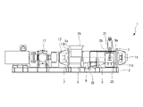
- FIG. 1 is a top view of a stock adjusting device according to an embodiment of the present invention
- FIG. FIG. 2 is a side view of the stock conditioning device of FIG. 1
- 3 is a partial cross-sectional view of FIG. 2
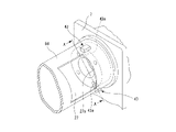
- FIG. 2 is a partially broken perspective view of the other end portion of the stock adjusting device of FIG. 1.
- FIG. FIG. 5 is a cross-sectional view taken along the line AA of FIG. 4;
- FIG. Reference numeral 3 indicates a gantry base, and this gantry base 3 is provided with brackets 5 and 7, and the bracket 7 is formed with a circular hole 7a.
- Reference numeral 9 indicates a cylindrical cylinder, and flanges 9a are formed at both ends of the cylindrical cylinder 9. As shown in FIG. The cylindrical cylinder 9 is horizontally installed on the gantry base 3 with its intermediate portion supported by the bracket 5 and both ends supported by the brackets 7 . A flange 9 a of the cylindrical cylinder 9 abuts a flange 7 b of the bracket 7 . As indicated by the arrow in FIG. 1, the stock material such as waste paper is conveyed from one side to the other side in the cylindrical cylinder 9 .
- Reference numeral 11 indicates a bearing device, which is attached to the other side of the cylindrical cylinder 9 and closes the other side opening of the cylindrical cylinder 9, as shown in detail in FIG.
- a flange 11 b is formed on the case 11 a of the bearing device 11 and contacts the bracket 7 .
- the flange 11b of the bearing device 11, the flange 9a of the cylindrical cylinder 9, and the flange 7b of the bracket 7 are connected with bolts.
- one side opening of the cylindrical cylinder 9 is also closed by the bearing device 13 .
- a flange 11b of the bearing device 11 is formed with four internal threads (not shown).
- a female screw is not formed on the flange 13b of the bearing device 13.
- a rotating shaft 15 passes through the center of the cylindrical cylinder 9, and both ends thereof are rotatably supported by bearing devices 11 and 13, respectively.
- One end of the rotating shaft 15 is connected to a drive motor 17 .
- a feed screw (not shown) is provided on one side of the rotating shaft 15 .
- the blades 21 are provided in an intersecting manner while being inclined in the feed direction and the feed back direction. Also, the blades 21 are arranged with a 90° shift in the circumferential direction. Therefore, when viewed from a cross section perpendicular to the axial direction, there are locations where two or four blades 21 are arranged in the circumferential direction.
- Reference numeral 23 indicates a blocking fitting.
- the cylindrical cylinder 9 has a multi-layered structure, and the blocking fitting 23 protrudes from the inner cylinder 9d forming the inner surface of the cylindrical cylinder 9 toward the center of the shaft, and protrudes from the highest position on the inner surface. , so that it is in a vertical position and extends downward from above.
- the blocking metal fitting 23 has a square plate shape, and a plate surface 23a facing the blade 21 is a vertical plane.
- a cylindrical inlet 25 is provided on one side in the axial direction of the cylindrical cylinder 9 so as to communicate with the inside and the upper side. Further, an extraction port 27 is provided on the other side in the axial direction so as to communicate with the inside of the cylindrical cylinder 9 on the front side. The outlet 27 is opened and closed by a lid 29 . An adjusting damper 33 connected to the air cylinder 31 is connected to the lid body 29 . Therefore, the inside is kept at a predetermined pressure.
- the cylindrical cylinder 9 has a missing lower part in the middle in the axial direction, and the missing part is closed with a punching metal (not shown) so that water can flow therethrough.
- a drain port 35 continues around the missing portion.
- a reference numeral 37 indicates an annular member, and this annular member 37 has an annular shape with a certain thickness, and has a round hole 37a at its center. The diameter of the round hole 37a is set so that the rotary shaft 15 can be rotatably inserted therein.
- An annular groove 37b is formed in an end face 37d on the other side of the annular member 37.
- Four bolt insertion holes 37c are formed in the annular member 37, and the bolt insertion holes 37c are in communication with an end face 37d exposed on one side of the annular member 37 and the groove 37b.
- the end face 37d is a vertical plane.
- the other end space portion 39 is formed between the edge 27a on the other side of the outlet 27 inside the cylindrical cylinder 9 and the end portion 9b on the other side of the cylindrical cylinder 9 .
- the annular member 37 is provided in the other end space portion 39 and fills the gap on the other side of the other end space portion 39 .
- the rotary shaft 15 is inserted through the round hole 37 a of the annular member 37 .
- a bolt 41 is inserted through the bolt insertion hole 37c, and the bolt 41 is screwed into a female screw 11c formed in the flange 11b of the bearing device 11. As shown in FIG.
- the head upper surface 41a of the bolt 41 is substantially flush with the end surface 37d, and the end surface 37d side is planar.
- two scraper fittings 43, 43 are provided on one side of the annular member 37 of the other end space portion 39.
- the scraper metal fitting 43 has the same shape as the blocking metal fitting 23 and protrudes from the inner surface of the cylindrical cylinder 9 toward the center of the shaft.
- One scraper fitting 43 protrudes from the highest position on the inner surface, and therefore extends downward from above in a vertical posture.
- the other scraper fitting 43 extends obliquely.
- the two scraper fittings 43, 43 are arranged with a 135° circumferential shift. In FIG. 3, only scraper metal fittings 43, 43 extending downward are shown for convenience of visual recognition.
- the scraper fittings 43, 43 are close to the blades 21a, 21a, .
- the stock adjusting device 1 is constructed as described above.
- a stock material containing a large amount of hot-melt, sticky substances, etc. is introduced into the cylindrical cylinder 9 through the inlet 25 . Inside the cylindrical cylinder 9, it is fed toward the outlet 27 by the feeding screw. Then, when the stock material reaches the other side of the cylindrical cylinder 9, the blade 21 rotating together with the rotating shaft 15 causes a return-like state between the feed direction and the return direction. In addition, since the blocking metal fittings 23 fixed between the blades 21 enter in order, the stock material is prevented from rotating together with the blades 21. ⁇
- the plate surface 43a of the scraper metal fitting 43 is also close to the end surface 37d side, and large hot-melt or sticky substances do not enter the small gap. If a large amount of hot-melt or sticky material enters, the paper materials will be laminated and adhered to each other around that point, and it may become difficult to scrape off the material with the scraper fitting 43, but there is no need to worry about that. Further, since the blades 21a, 21a, . . . .
Landscapes
- Engineering & Computer Science (AREA)
- Mechanical Engineering (AREA)
- Life Sciences & Earth Sciences (AREA)
- Wood Science & Technology (AREA)
- Chemical & Material Sciences (AREA)
- Chemical Kinetics & Catalysis (AREA)
- Food Science & Technology (AREA)
- Paper (AREA)
- Crushing And Pulverization Processes (AREA)
- Accessories For Mixers (AREA)
- Mixers Of The Rotary Stirring Type (AREA)
Abstract
Priority Applications (2)
| Application Number | Priority Date | Filing Date | Title |
|---|---|---|---|
| CN202180095034.1A CN116897232B (zh) | 2021-03-22 | 2021-04-20 | 纸料调整装置 |
| US18/280,656 US12571160B2 (en) | 2021-03-22 | 2021-04-20 | Paper stock modification device |
Applications Claiming Priority (2)
| Application Number | Priority Date | Filing Date | Title |
|---|---|---|---|
| JP2021-047688 | 2021-03-22 | ||
| JP2021047688A JP7506407B2 (ja) | 2021-03-22 | 2021-03-22 | 紙料調整装置 |
Publications (1)
| Publication Number | Publication Date |
|---|---|
| WO2022201560A1 true WO2022201560A1 (fr) | 2022-09-29 |
Family
ID=83396597
Family Applications (1)
| Application Number | Title | Priority Date | Filing Date |
|---|---|---|---|
| PCT/JP2021/015961 Ceased WO2022201560A1 (fr) | 2021-03-22 | 2021-04-20 | Dispositif de modification de pâte à papier |
Country Status (4)
| Country | Link |
|---|---|
| US (1) | US12571160B2 (fr) |
| JP (1) | JP7506407B2 (fr) |
| CN (1) | CN116897232B (fr) |
| WO (1) | WO2022201560A1 (fr) |
Cited By (1)
| Publication number | Priority date | Publication date | Assignee | Title |
|---|---|---|---|---|
| CN120037816A (zh) * | 2025-04-23 | 2025-05-27 | 潍坊杰高非织材料科技有限公司 | 一种隔离纸生产用纤维浆料匀浆装置 |
Citations (4)
| Publication number | Priority date | Publication date | Assignee | Title |
|---|---|---|---|---|
| JPS63264992A (ja) * | 1987-04-17 | 1988-11-01 | 株式会社岩科製作所 | 製紙用ニ−ダ− |
| JPH01122097U (fr) * | 1988-02-16 | 1989-08-18 | ||
| CN103132354A (zh) * | 2011-11-24 | 2013-06-05 | 金红叶纸业集团有限公司 | 纤维预处理装置 |
| WO2021009988A1 (fr) * | 2019-07-16 | 2021-01-21 | 株式会社大善 | Procédé de récupération de fibre à partir d'un rejet de tamisage et dispositif de prétraitement de tri de fines destiné à être utilisé dans un procédé de récupération de fibre |
Family Cites Families (6)
| Publication number | Priority date | Publication date | Assignee | Title |
|---|---|---|---|---|
| AT360828B (de) * | 1978-03-06 | 1981-02-10 | Escher Wyss Gmbh | Sortiervorrichtung fuer aus altpapier gewonnene stofffluessigkeit |
| JPS6422097U (fr) | 1987-07-30 | 1989-02-03 | ||
| US4984196A (en) | 1988-05-25 | 1991-01-08 | Texas Instruments, Incorporated | High performance bipolar differential sense amplifier in a BiCMOS SRAM |
| JP3433919B2 (ja) | 2000-06-23 | 2003-08-04 | 株式会社大善 | 紙料調整装置 |
| CN101092800B (zh) * | 2007-07-30 | 2010-12-08 | 北京亿同多欧纸业投资有限公司 | 造纸浆料置换洗涤浓缩装置 |
| CN107051355A (zh) * | 2017-03-30 | 2017-08-18 | 山东里德工程技术有限公司 | 一种单轴自清洁反应器 |
-
2021
- 2021-03-22 JP JP2021047688A patent/JP7506407B2/ja active Active
- 2021-04-20 WO PCT/JP2021/015961 patent/WO2022201560A1/fr not_active Ceased
- 2021-04-20 CN CN202180095034.1A patent/CN116897232B/zh active Active
- 2021-04-20 US US18/280,656 patent/US12571160B2/en active Active
Patent Citations (4)
| Publication number | Priority date | Publication date | Assignee | Title |
|---|---|---|---|---|
| JPS63264992A (ja) * | 1987-04-17 | 1988-11-01 | 株式会社岩科製作所 | 製紙用ニ−ダ− |
| JPH01122097U (fr) * | 1988-02-16 | 1989-08-18 | ||
| CN103132354A (zh) * | 2011-11-24 | 2013-06-05 | 金红叶纸业集团有限公司 | 纤维预处理装置 |
| WO2021009988A1 (fr) * | 2019-07-16 | 2021-01-21 | 株式会社大善 | Procédé de récupération de fibre à partir d'un rejet de tamisage et dispositif de prétraitement de tri de fines destiné à être utilisé dans un procédé de récupération de fibre |
Cited By (1)
| Publication number | Priority date | Publication date | Assignee | Title |
|---|---|---|---|---|
| CN120037816A (zh) * | 2025-04-23 | 2025-05-27 | 潍坊杰高非织材料科技有限公司 | 一种隔离纸生产用纤维浆料匀浆装置 |
Also Published As
| Publication number | Publication date |
|---|---|
| US12571160B2 (en) | 2026-03-10 |
| CN116897232B (zh) | 2025-07-04 |
| JP2022146627A (ja) | 2022-10-05 |
| JP7506407B2 (ja) | 2024-06-26 |
| CN116897232A (zh) | 2023-10-17 |
| US20240173683A1 (en) | 2024-05-30 |
Similar Documents
| Publication | Publication Date | Title |
|---|---|---|
| US11084042B2 (en) | Dual-shaft shredder with interchangeable cutting blade set and releasable shaft ends | |
| RU2378429C1 (ru) | Устройство для обезвоживания сыпучего и текучего загружаемого материала путем его уплотнения | |
| CA2851289C (fr) | Extrudeuse a vis | |
| WO2022201560A1 (fr) | Dispositif de modification de pâte à papier | |
| US3960332A (en) | Defibering apparatus for paper making stock | |
| JP4051395B1 (ja) | 回転加圧脱水機 | |
| EP2454059A1 (fr) | Couteau en feuille et cylindre massif à couteau | |
| US5643450A (en) | Filter apparatus for fluids, in particular for thermoplastic synthetic plastics material fluid | |
| WO2012073216A1 (fr) | Dispositif de séparation de matériaux composites | |
| DE102018105588B4 (de) | Zentrifugalabscheider zum Abscheiden von Öltröpfchen aus dem Kurbelgehäuseentlüftungsgas einer Brennkraftmaschine | |
| DE69712353T2 (de) | Verfahren und vorrichtung zur wiederaufbereitung der verschiedenen komponenten eines mehrlagigen materials | |
| DE102016100959A1 (de) | Rotierende Pumpe und Sicherungsblech | |
| CA2023457C (fr) | Rouleau aspirant | |
| JP2637364B2 (ja) | 遠心分離機 | |
| JP2010000555A (ja) | シート材打ち抜き装置 | |
| KR102082719B1 (ko) | 협잡물 처리기 | |
| EP2868360A1 (fr) | Filtre rotatif | |
| US7467755B2 (en) | Parts separator apparatus and method of shredding | |
| JP2005230852A (ja) | スクリュープレス脱水装置 | |
| US7285180B2 (en) | Perforated deck made out of a plurality of segments | |
| CN111432932A (zh) | 适应性结构固体分流器和粉碎器 | |
| CN103069183B (zh) | 通过法兰连接的轴承中的油脂通道 | |
| AU2015323418B2 (en) | Centrifuge seals and sealing arrangements and centrifuges containing the same | |
| DE102011017038A1 (de) | Vorrichtung zur Erzeugung von Scherbeneis | |
| KR20140136661A (ko) | 벨트필터프레스의 스크레이핑 장치 |
Legal Events
| Date | Code | Title | Description |
|---|---|---|---|
| 121 | Ep: the epo has been informed by wipo that ep was designated in this application |
Ref document number: 21933161 Country of ref document: EP Kind code of ref document: A1 |
|
| WWE | Wipo information: entry into national phase |
Ref document number: 202180095034.1 Country of ref document: CN |
|
| WWE | Wipo information: entry into national phase |
Ref document number: 18280656 Country of ref document: US |
|
| NENP | Non-entry into the national phase |
Ref country code: DE |
|
| 122 | Ep: pct application non-entry in european phase |
Ref document number: 21933161 Country of ref document: EP Kind code of ref document: A1 |
|
| WWG | Wipo information: grant in national office |
Ref document number: 202180095034.1 Country of ref document: CN |
|
| WWG | Wipo information: grant in national office |
Ref document number: 18280656 Country of ref document: US |