WO2022201732A1 - Système de détermination de somnolence et procédé de détermination de somnolence - Google Patents
Système de détermination de somnolence et procédé de détermination de somnolence Download PDFInfo
- Publication number
- WO2022201732A1 WO2022201732A1 PCT/JP2022/000177 JP2022000177W WO2022201732A1 WO 2022201732 A1 WO2022201732 A1 WO 2022201732A1 JP 2022000177 W JP2022000177 W JP 2022000177W WO 2022201732 A1 WO2022201732 A1 WO 2022201732A1
- Authority
- WO
- WIPO (PCT)
- Prior art keywords
- drowsiness
- occupant
- head
- determination
- information
- Prior art date
- Legal status (The legal status is an assumption and is not a legal conclusion. Google has not performed a legal analysis and makes no representation as to the accuracy of the status listed.)
- Ceased
Links
Images





Classifications
-
- A—HUMAN NECESSITIES
- A61—MEDICAL OR VETERINARY SCIENCE; HYGIENE
- A61B—DIAGNOSIS; SURGERY; IDENTIFICATION
- A61B5/00—Measuring for diagnostic purposes; Identification of persons
- A61B5/16—Devices for psychotechnics; Testing reaction times ; Devices for evaluating the psychological state
- A61B5/18—Devices for psychotechnics; Testing reaction times ; Devices for evaluating the psychological state for vehicle drivers or machine operators
-
- A—HUMAN NECESSITIES
- A61—MEDICAL OR VETERINARY SCIENCE; HYGIENE
- A61B—DIAGNOSIS; SURGERY; IDENTIFICATION
- A61B5/00—Measuring for diagnostic purposes; Identification of persons
- A61B5/0059—Measuring for diagnostic purposes; Identification of persons using light, e.g. diagnosis by transillumination, diascopy, fluorescence
- A61B5/0077—Devices for viewing the surface of the body, e.g. camera, magnifying lens
-
- A—HUMAN NECESSITIES
- A61—MEDICAL OR VETERINARY SCIENCE; HYGIENE
- A61B—DIAGNOSIS; SURGERY; IDENTIFICATION
- A61B5/00—Measuring for diagnostic purposes; Identification of persons
- A61B5/103—Measuring devices for testing the shape, pattern, colour, size or movement of the body or parts thereof, for diagnostic purposes
- A61B5/11—Measuring movement of the entire body or parts thereof, e.g. head or hand tremor or mobility of a limb
- A61B5/1103—Detecting muscular movement of the eye, e.g. eyelid movement
-
- A—HUMAN NECESSITIES
- A61—MEDICAL OR VETERINARY SCIENCE; HYGIENE
- A61B—DIAGNOSIS; SURGERY; IDENTIFICATION
- A61B5/00—Measuring for diagnostic purposes; Identification of persons
- A61B5/103—Measuring devices for testing the shape, pattern, colour, size or movement of the body or parts thereof, for diagnostic purposes
- A61B5/11—Measuring movement of the entire body or parts thereof, e.g. head or hand tremor or mobility of a limb
- A61B5/1116—Determining posture transitions
-
- A—HUMAN NECESSITIES
- A61—MEDICAL OR VETERINARY SCIENCE; HYGIENE
- A61B—DIAGNOSIS; SURGERY; IDENTIFICATION
- A61B5/00—Measuring for diagnostic purposes; Identification of persons
- A61B5/103—Measuring devices for testing the shape, pattern, colour, size or movement of the body or parts thereof, for diagnostic purposes
- A61B5/11—Measuring movement of the entire body or parts thereof, e.g. head or hand tremor or mobility of a limb
- A61B5/1126—Measuring movement of the entire body or parts thereof, e.g. head or hand tremor or mobility of a limb using a particular sensing technique
- A61B5/1128—Measuring movement of the entire body or parts thereof, e.g. head or hand tremor or mobility of a limb using a particular sensing technique using image analysis
-
- A—HUMAN NECESSITIES
- A61—MEDICAL OR VETERINARY SCIENCE; HYGIENE
- A61B—DIAGNOSIS; SURGERY; IDENTIFICATION
- A61B5/00—Measuring for diagnostic purposes; Identification of persons
- A61B5/16—Devices for psychotechnics; Testing reaction times ; Devices for evaluating the psychological state
- A61B5/162—Testing reaction times
-
- A—HUMAN NECESSITIES
- A61—MEDICAL OR VETERINARY SCIENCE; HYGIENE
- A61B—DIAGNOSIS; SURGERY; IDENTIFICATION
- A61B5/00—Measuring for diagnostic purposes; Identification of persons
- A61B5/48—Other medical applications
- A61B5/4887—Locating particular structures in or on the body
-
- A—HUMAN NECESSITIES
- A61—MEDICAL OR VETERINARY SCIENCE; HYGIENE
- A61B—DIAGNOSIS; SURGERY; IDENTIFICATION
- A61B5/00—Measuring for diagnostic purposes; Identification of persons
- A61B5/68—Arrangements of detecting, measuring or recording means, e.g. sensors, in relation to patient
- A61B5/6801—Arrangements of detecting, measuring or recording means, e.g. sensors, in relation to patient specially adapted to be attached to or worn on the body surface
- A61B5/6802—Sensor mounted on worn items
-
- A—HUMAN NECESSITIES
- A61—MEDICAL OR VETERINARY SCIENCE; HYGIENE
- A61B—DIAGNOSIS; SURGERY; IDENTIFICATION
- A61B5/00—Measuring for diagnostic purposes; Identification of persons
- A61B5/68—Arrangements of detecting, measuring or recording means, e.g. sensors, in relation to patient
- A61B5/6887—Arrangements of detecting, measuring or recording means, e.g. sensors, in relation to patient mounted on external non-worn devices, e.g. non-medical devices
- A61B5/6893—Cars
-
- A—HUMAN NECESSITIES
- A61—MEDICAL OR VETERINARY SCIENCE; HYGIENE
- A61B—DIAGNOSIS; SURGERY; IDENTIFICATION
- A61B5/00—Measuring for diagnostic purposes; Identification of persons
- A61B5/72—Signal processing specially adapted for physiological signals or for diagnostic purposes
- A61B5/7235—Details of waveform analysis
- A61B5/7264—Classification of physiological signals or data, e.g. using neural networks, statistical classifiers, expert systems or fuzzy systems
- A61B5/7267—Classification of physiological signals or data, e.g. using neural networks, statistical classifiers, expert systems or fuzzy systems involving training the classification device
-
- A—HUMAN NECESSITIES
- A61—MEDICAL OR VETERINARY SCIENCE; HYGIENE
- A61B—DIAGNOSIS; SURGERY; IDENTIFICATION
- A61B5/00—Measuring for diagnostic purposes; Identification of persons
- A61B5/72—Signal processing specially adapted for physiological signals or for diagnostic purposes
- A61B5/7271—Specific aspects of physiological measurement analysis
- A61B5/7275—Determining trends in physiological measurement data; Predicting development of a medical condition based on physiological measurements, e.g. determining a risk factor
-
- A—HUMAN NECESSITIES
- A61—MEDICAL OR VETERINARY SCIENCE; HYGIENE
- A61B—DIAGNOSIS; SURGERY; IDENTIFICATION
- A61B5/00—Measuring for diagnostic purposes; Identification of persons
- A61B5/72—Signal processing specially adapted for physiological signals or for diagnostic purposes
- A61B5/7271—Specific aspects of physiological measurement analysis
- A61B5/7282—Event detection, e.g. detecting unique waveforms indicative of a medical condition
-
- A—HUMAN NECESSITIES
- A61—MEDICAL OR VETERINARY SCIENCE; HYGIENE
- A61B—DIAGNOSIS; SURGERY; IDENTIFICATION
- A61B5/00—Measuring for diagnostic purposes; Identification of persons
- A61B5/74—Details of notification to user or communication with user or patient; User input means
- A61B5/7455—Details of notification to user or communication with user or patient; User input means characterised by tactile indication, e.g. vibration or electrical stimulation
-
- A—HUMAN NECESSITIES
- A61—MEDICAL OR VETERINARY SCIENCE; HYGIENE
- A61B—DIAGNOSIS; SURGERY; IDENTIFICATION
- A61B5/00—Measuring for diagnostic purposes; Identification of persons
- A61B5/74—Details of notification to user or communication with user or patient; User input means
- A61B5/746—Alarms related to a physiological condition, e.g. details of setting alarm thresholds or avoiding false alarms
-
- B—PERFORMING OPERATIONS; TRANSPORTING
- B60—VEHICLES IN GENERAL
- B60K—ARRANGEMENT OR MOUNTING OF PROPULSION UNITS OR OF TRANSMISSIONS IN VEHICLES; ARRANGEMENT OR MOUNTING OF PLURAL DIVERSE PRIME-MOVERS IN VEHICLES; AUXILIARY DRIVES FOR VEHICLES; INSTRUMENTATION OR DASHBOARDS FOR VEHICLES; ARRANGEMENTS IN CONNECTION WITH COOLING, AIR INTAKE, GAS EXHAUST OR FUEL SUPPLY OF PROPULSION UNITS IN VEHICLES
- B60K28/00—Safety devices for propulsion-unit control, specially adapted for, or arranged in, vehicles, e.g. preventing fuel supply or ignition in the event of potentially dangerous conditions
- B60K28/02—Safety devices for propulsion-unit control, specially adapted for, or arranged in, vehicles, e.g. preventing fuel supply or ignition in the event of potentially dangerous conditions responsive to conditions relating to the driver
- B60K28/06—Safety devices for propulsion-unit control, specially adapted for, or arranged in, vehicles, e.g. preventing fuel supply or ignition in the event of potentially dangerous conditions responsive to conditions relating to the driver responsive to incapacity of driver
-
- B—PERFORMING OPERATIONS; TRANSPORTING
- B60—VEHICLES IN GENERAL
- B60W—CONJOINT CONTROL OF VEHICLE SUB-UNITS OF DIFFERENT TYPE OR DIFFERENT FUNCTION; CONTROL SYSTEMS SPECIALLY ADAPTED FOR HYBRID VEHICLES; ROAD VEHICLE DRIVE CONTROL SYSTEMS FOR PURPOSES NOT RELATED TO THE CONTROL OF A PARTICULAR SUB-UNIT
- B60W40/00—Estimation or calculation of non-directly measurable driving parameters for road vehicle drive control systems not related to the control of a particular sub unit, e.g. by using mathematical models
- B60W40/08—Estimation or calculation of non-directly measurable driving parameters for road vehicle drive control systems not related to the control of a particular sub unit, e.g. by using mathematical models related to drivers or passengers
-
- G—PHYSICS
- G06—COMPUTING OR CALCULATING; COUNTING
- G06V—IMAGE OR VIDEO RECOGNITION OR UNDERSTANDING
- G06V20/00—Scenes; Scene-specific elements
- G06V20/50—Context or environment of the image
- G06V20/59—Context or environment of the image inside of a vehicle, e.g. relating to seat occupancy, driver state or inner lighting conditions
- G06V20/597—Recognising the driver's state or behaviour, e.g. attention or drowsiness
-
- G—PHYSICS
- G08—SIGNALLING
- G08G—TRAFFIC CONTROL SYSTEMS
- G08G1/00—Traffic control systems for road vehicles
- G08G1/16—Anti-collision systems
-
- A—HUMAN NECESSITIES
- A61—MEDICAL OR VETERINARY SCIENCE; HYGIENE
- A61B—DIAGNOSIS; SURGERY; IDENTIFICATION
- A61B2503/00—Evaluating a particular growth phase or type of persons or animals
- A61B2503/20—Workers
- A61B2503/22—Motor vehicles operators, e.g. drivers, pilots, captains
-
- A—HUMAN NECESSITIES
- A61—MEDICAL OR VETERINARY SCIENCE; HYGIENE
- A61B—DIAGNOSIS; SURGERY; IDENTIFICATION
- A61B2562/00—Details of sensors; Constructional details of sensor housings or probes; Accessories for sensors
- A61B2562/02—Details of sensors specially adapted for in-vivo measurements
- A61B2562/0219—Inertial sensors, e.g. accelerometers, gyroscopes, tilt switches
-
- A—HUMAN NECESSITIES
- A61—MEDICAL OR VETERINARY SCIENCE; HYGIENE
- A61B—DIAGNOSIS; SURGERY; IDENTIFICATION
- A61B5/00—Measuring for diagnostic purposes; Identification of persons
- A61B5/16—Devices for psychotechnics; Testing reaction times ; Devices for evaluating the psychological state
- A61B5/163—Devices for psychotechnics; Testing reaction times ; Devices for evaluating the psychological state by tracking eye movement, gaze, or pupil change
Definitions
- the present disclosure relates to a drowsiness determination system and a drowsiness determination method for determining drowsiness of an occupant.
- Patent Document 1 discloses a drowsiness determination device. This drowsiness determination device determines whether or not an occupant is drowsy based on vehicle information indicating the amount of change in vehicle attitude relative to the road surface and head information indicating the amount of change in the occupant's head relative to a predetermined position. It has a judgment unit that Then, when the vehicle posture changes, the determination unit determines whether the occupant's head moves in the same direction as the vehicle posture change direction, and the time point at which the occupant's head changes relative to the time point at which the vehicle posture changes. is longer than a predetermined time, it is determined that the occupant is drowsy.
- the present disclosure provides a drowsiness determination system and the like that can improve the accuracy of determining drowsiness of a passenger.
- a drowsiness determination system includes a first acquisition unit, a second acquisition unit, a third acquisition unit, and a determination unit.
- the first acquisition unit acquires vibration information indicating vibration of the vehicle.
- the second acquisition unit acquires head information indicating changes in the head of the occupant.
- the third acquisition unit acquires sitting height information indicating the sitting height of the passenger.
- the determination unit determines whether or not the occupant is drowsy based on the head information and the sitting height information when the vibration information indicates that the vehicle is vibrating.
- a drowsiness determination method includes a first acquisition step, a second acquisition step, a third acquisition step, and a determination step.
- vibration information indicating vibration of the vehicle is obtained.
- head information indicating the movement of the head of the occupant is obtained.
- sitting height information indicating the sitting height of the passenger is acquired.
- FIG. 1 is a block diagram showing an outline of a drowsiness determination system according to Embodiment 1.
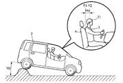
- FIG. FIG. 2 is a diagram showing an example of the state of the vehicle and the head of the occupant at the time when the amount of variation in the attitude of the vehicle reaches its peak.
- FIG. 3 is a diagram showing an example of the state of the vehicle and the occupant's head when the amount of variation in the occupant's head reaches a peak.
- FIG. 4 is a waveform diagram showing an example of temporal changes in the amount of change in the attitude of the vehicle and the amount of change in the head of the occupant.
- FIG. 5 is a scatter diagram showing the correlation between occupant sleepiness level, delay time, and occupant's sitting height.
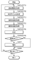
- FIG. 6 is a flowchart showing an operation example of the drowsiness determination system according to Embodiment 1.
- FIG. FIG. 7 is a block diagram showing an outline of a drowsiness determination system according to Embodiment 2.
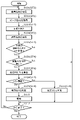
- FIG. 8 is a flow chart showing an operation example of the drowsiness determination system according to the second embodiment.
- FIG. 9 is a scatter diagram showing the correlation between occupant drowsiness level, delay time, and occupant's sitting height based on the peak value of the amount of variation in vehicle posture in the drowsiness determination system according to the third embodiment. ) is when the peak value is small, (b) is when the peak value is medium, and (c) is when the peak value is large.
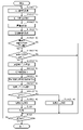
- FIG. 10 is a flow chart showing an operation example of the drowsiness determination system according to the third embodiment.
- FIG. 11 is a correlation diagram of the delay time with respect to the peak value of the amount of change in the attitude of the vehicle in the drowsiness determination system according to the third embodiment.
- FIG. 12 is a flow chart showing an operation example of the drowsiness determination system according to the fourth embodiment.
- a drowsiness determination system includes a first acquisition unit, a second acquisition unit, a third acquisition unit, and a determination unit.
- the first acquisition unit acquires vibration information indicating vibration of the vehicle.
- the second acquisition unit acquires head information indicating changes in the head of the occupant.
- the third acquisition unit acquires sitting height information indicating the sitting height of the passenger.
- the determination unit determines whether or not the occupant is drowsy based on the head information and the sitting height information when the vibration information indicates that the vehicle is vibrating.
- the head information depends on the sitting height of the occupant
- the third acquisition unit acquires the sitting height information by estimating the sitting height based on a captured image of the head.
- the passenger can use the sitting height information without having to enter it in advance, so there is the advantage that the passenger's work is reduced and convenience is easily improved.
- the determination unit determines whether the occupant is drowsy by comparing the head information with a threshold value.
- the determination unit determines the threshold from a plurality of threshold candidates based on the sitting height information.
- the determination unit includes a determination model that receives the vibration information and the head information and outputs a determination result as to whether or not the occupant is drowsy. there is The determination unit determines the determination model from a plurality of determination model candidates based on the sitting height information.
- the head information includes a delay time until the head moves in a predetermined period from the time when the vibration of the vehicle occurs, and the head relative to a predetermined position. at least one of a maximum amplitude of head variation, an average amplitude of head variation for the given position, and a variance of head position for the given position.
- the drowsiness of the occupant can be determined using one or more parameters that can vary according to the drowsiness of the occupant, so there is the advantage that it is easy to improve the accuracy of determining the drowsiness of the occupant.
- the determination unit when the predetermined period elapses or the magnitude of vibration of the vehicle exceeds a predetermined value, the determination unit resets the clock for the predetermined period.
- the determination unit causes the occupant to feel drowsiness during a period from resetting the timing of the predetermined period until the magnitude of vibration of the vehicle exceeds the predetermined value. does not determine whether or not there is
- the determination unit decelerates the vehicle when the vehicle has not vibrated for a predetermined period of time or longer.
- determining the drowsiness of the occupants during such periods also has the advantage of making it easier to take measures such as encouraging wakefulness of the occupants. .
- the determination unit further determines whether the occupant is drowsy based on the magnitude of the vibration information.
- the range in which the vibration information is determined to be small is It is wider than the range in which the vibration information is determined to be large.
- the delay time to the movement of the head with respect to the actual vehicle vibration has little difference when the vehicle vibration is small, and increases sharply as the vehicle vibration increases. Since the magnitude of the vibration information can be determined by taking into account the drowsiness, there is an advantage that it is possible to determine drowsiness with higher accuracy.
- the determination unit further obtains a representative value of the eyelid position within a predetermined period of the occupant from the head information based on the captured image of the head, It is determined whether or not the occupant is drowsy in consideration of the representative value of the eyelid position.
- the determination unit determines head drowsiness determined based on the head information and the sitting height information, and eyelid drowsiness determined based on the representative value of the eyelid position. are obtained respectively, and the drowsiness of the occupant is determined by weighting the drowsiness of the head and the drowsiness of the eyelids.
- the determination unit determines whether the occupant is wearing eyeglasses based on the head information, and determines whether the occupant is wearing eyeglasses. (2) determines the type of eyeglasses, weights the head sleepiness and the eyelid sleepiness according to the determination result, and determines the drowsiness of the occupant.
- the error in eyelid drowsiness due to the presence or absence of eyeglasses, and the type of eyeglasses if eyeglasses are worn, can be covered by head drowsiness, which has the advantage of increasing the accuracy of drowsiness determination.
- the determination unit increases the weighting of the eyelid drowsiness with respect to the head drowsiness, and the occupant wears the sunglasses. If so, the eyelid drowsiness is weighted less than the head drowsiness.
- the error of eyelid drowsiness caused by sunglasses can be covered by head drowsiness, so there is an advantage that the accuracy of drowsiness determination increases.
- a drowsiness determination method includes a first acquisition step, a second acquisition step, a third acquisition step, and a determination step.
- vibration information indicating vibration of the vehicle is obtained.
- head information indicating the movement of the head of the occupant is obtained.
- sitting height information indicating the sitting height of the passenger is acquired.
- the head information depends on the sitting height of the occupant
- the determination step further determines whether the occupant is drowsy based on the magnitude of the vibration information.
- the determining step further obtains a representative value of eyelid positions within a predetermined period of the occupant from the head information based on the captured image of the head, and It is determined whether or not the occupant is drowsy in consideration of the representative value of the eyelid position.
- each figure is a schematic diagram and is not necessarily strictly illustrated. Moreover, in each figure, the same code
- FIG. 1 is a block diagram showing an outline of a drowsiness determination system 100 according to Embodiment 1.
- the drowsiness determination system 100 according to Embodiment 1 is a system that is used in a moving object such as a vehicle 2 (see FIG. 2) to assist the driving of the vehicle 2 .
- drowsiness determination system 100 is realized by an in-vehicle device, but may be realized by an external device brought in from the outside of vehicle 2 .
- the occupant 3 (see FIG. 2) targeted by the drowsiness determination system 100 is a driver of a vehicle sitting in the driver's seat. It may be a crew member.
- the drowsiness determination system 100 includes a first acquisition unit 11, a second acquisition unit 12, a third acquisition unit 13, a determination unit 14, and a notification unit 15, as shown in FIG. Note that the drowsiness determination system 100 may include at least the first acquisition unit 11, the second acquisition unit 12, the third acquisition unit 13, and the determination unit 14, and may not include the notification unit 15.
- the first acquisition unit 11 acquires vibration information indicating vibration of the vehicle 2 .
- the first acquisition unit 11 is the execution subject of the first acquisition step ST1 in the drowsiness determination method.
- the first acquisition unit 11 acquires vibration information by acquiring the detection result output by the vibration detection unit 21 .
- the vibration detection unit 21 is, for example, a gyro sensor mounted on the vehicle 2, and detects the vibration of the vehicle 2, in other words, the amount of change in the posture of the vehicle 2 with respect to the road surface.
- the amount of change in the attitude of the vehicle 2 is represented by the magnitude of the pitch angle, roll angle, or yaw angle of the vehicle 2 with respect to the road surface. Note that the amount of change in the attitude of the vehicle 2 may be represented by, for example, the distance between one longitudinal end of the vehicle 2 and the road surface.
- the vibration detection unit 21 is not limited to a gyro sensor, and may be an acceleration sensor that detects the acceleration of the vehicle 2, for example.
- the second acquisition unit 12 acquires head information indicating the movement of the head 31 of the occupant 3 .
- the second acquisition unit 12 is the executing entity of the second acquisition step ST2 in the drowsiness determination method.
- the second acquisition unit 12 calculates the variation amount of the head 31 of the occupant 3 with respect to a predetermined position in the vehicle 2 by, for example, performing appropriate image processing on the captured image, and calculates the calculated head 31 of the occupant 3.
- Head information is acquired based on the variation amount of the part 31 .
- the captured image is an image including the head 31 of the passenger 3 and captured by a camera 22 mounted on the vehicle 2, for example.
- the predetermined position is, for example, the position of the headrest of the seat 4 on which the passenger 3 sits, the position of the side door, or the like.
- the second acquisition unit 12 extracts feature points of the head 31 of the occupant 3 by executing appropriate image processing on the captured image, and calculates the coordinates of the feature points.
- the feature point is, for example, the top of the head 31 of the occupant 3 .
- the feature point may be other than the top of the head, such as the eyes of the occupant 3, for example.
- the second acquisition unit 12 calculates the amount of change in the extracted feature points over time as the amount of change in the head 31 of the occupant 3 .
- the head information is the delay time Td (see FIG. 4).
- the delay time Td is the amount of change in the posture of the vehicle 2 (that is, the vibration of the vehicle 2) during a predetermined period T1 (see FIG. 4) from the time that the change in the posture of the vehicle 2 (that is, the vibration of the vehicle 2) occurs. is the time corresponding to the difference between the point in time when the peak is reached and the point in time when the variation amount of the head 31 of the occupant 3 reaches its peak.
- the delay time Td is not limited to this, and may be, for example, a time difference based on the point in time when the attitude of the vehicle 2 and the head 31 of the occupant 3 occur.
- FIG. 2 is a diagram showing an example of the state of the vehicle 2 and the heads 31 of the occupant 3 when the amount of variation in the posture of the vehicle 2 reaches its peak.
- FIG. 3 is a diagram showing an example of the state of the vehicle 2 and the head 31 of the occupant 3 when the variation amount of the head 31 of the occupant 3 reaches a peak. In both FIGS. 2 and 3, each variation is emphasized so that the variation of the head 31 of the vehicle 2 and the passenger 3 can be easily grasped visually.
- FIG. 4 is a waveform diagram showing an example of temporal changes in the amount of change in the attitude of the vehicle 2 and the amount of change in the head 31 of the occupant 3 .
- the attitude of the vehicle 2 changes in the pitch direction with respect to the road surface due to acceleration or deceleration of the vehicle 2, changes in road surface conditions, or the like. do.
- the head 31 of the occupant 3 is tilted in the traveling direction of the vehicle 2 (here, rightward in the drawing) so as to follow the change in the attitude of the vehicle 2 .
- the head 31 of the occupant 3 (here, the top of the head as a feature point) has a peak variation from an initial position P2, which is a distance Ho away from a predetermined position P1 (here, the position of the headrest). It fluctuates up to the position of the peak position P3, which is the value Hp.
- the posture of the vehicle 2 starts to fluctuate at time t0, then reaches the peak value Vp at time t1, and returns to the original state after time t3.
- the head 31 of the occupant 3 starts to change at time t3, which is delayed from the time t1 when the attitude of the vehicle 2 starts to change. It has returned to its original state. Therefore, in the example shown in FIG. 4, the delay time Td is the amount of change in the posture of the vehicle 2 during the predetermined period T1 from the time t1 when the change in the posture of the vehicle 2 (that is, the vibration of the vehicle 2) occurs.
- the time corresponds to the difference between the time t1 at which Vp is reached and the time t4 at which the variation amount of the head 31 of the occupant 3 reaches the peak value Hp.
- the occupant 3 makes a reflexive exercise in response to the change in the posture of the vehicle 2 in order to maintain its own posture.
- the occupant 3 immediately follows the behavior of the head 31 to the change in the attitude of the vehicle 2, so the change in the head 31 of the occupant 3 is delayed with respect to the change in the attitude of the vehicle 2. becomes shorter.
- the ability to maintain the posture of the occupant 3 deteriorates as the occupant 3 becomes less conscious.
- the delay time Td is a parameter that can vary according to the drowsiness of the crew member 3, and can be longer as the crew member 3 is more sleepy.
- the head information is the maximum value (hereinafter also referred to as “maximum value of head amplitude”) or average value (hereinafter referred to as “ (also referred to as “average value of head amplitude”).
- the head information may be dispersion of the position of the head 31 of the occupant 3 with respect to a predetermined position during the predetermined period T1 (hereinafter also referred to as “head position dispersion”).
- the maximum value of the head amplitude, the average value of the head amplitude, and the variance of the head position are all parameters that can vary depending on the drowsiness of the occupant 3, similar to the delay time Td. The greater the drowsiness of 3, the greater it can be.
- the head information includes the delay time Td until the head 31 changes in a predetermined period T1 from the time when the vibration of the vehicle 2 occurs, the maximum amplitude of the movement of the head 31 with respect to a predetermined position, the predetermined and at least one of the mean value of the amplitude of the variation of the head 31 with respect to the position of the head 31 and the variance of the position of the head 31 with respect to the predetermined position.
- the third acquisition unit 13 acquires sitting height information indicating the sitting height of the passenger 3.
- the third acquisition unit 13 is the execution subject of the third acquisition step ST3 in the drowsiness determination method.
- the “sitting height” referred to here may be, for example, the sitting height defined by physical measurements in a medical examination, or the height from the part where the occupant 3 is seated on the seat 4 to the top of the head 31 of the occupant 3. height. In the latter case, it can change depending on how the occupant 3 sits on the seat 4, such as the occupant 3 sitting shallowly in the seat 4, or the occupant 3 sitting deep in the seat 4, or the like.
- the third acquisition unit 13 acquires sitting height information by estimating the sitting height based on the captured image of the head 31 of the occupant 3 . Specifically, the third acquisition unit 13 extracts feature points of the head 31 of the occupant 3 by executing appropriate image processing on the captured image, and calculates the coordinates of the feature points. Here, the feature point is the top of the head 31 of the occupant 3 . Then, the third acquisition unit 13 calculates the height direction difference between the previously acquired coordinates indicating the position of the seating surface of the seat 4 and the calculated coordinates of the characteristic point, thereby determining the sitting height of the occupant 3. presume.
- the third acquisition unit 13 extracts the position where the occupant 3 sits on the seat 4 from the captured image,
- the coordinates of the extracted location may be calculated as coordinates indicating the position of the seating surface of the seat 4 .
- the third acquisition unit 13 can estimate the sitting height only from the captured image, and does not need to acquire the coordinates representing the position of the seating surface of the seat 4 in advance.
- the third acquisition unit 13 estimates the sitting height of the occupant 3 when the occupant 3 is seated on the seat 4 .
- the third acquisition unit 13 may estimate the sitting height of the occupant 3 in real time using the captured image each time the camera 22 mounted on the vehicle 2 captures an image. In the latter case, it is easy to accurately estimate the sitting height of the occupant 3 even when the posture of the occupant 3 changes from moment to moment.
- the determination unit 14 determines whether the occupant 3 is drowsy based on the head information and the sitting height information when the vibration information indicates that the vehicle 2 is vibrating.
- the determination unit 14 is the entity that executes determination step ST4 in the drowsiness determination method.
- the head information here, the delay time Td
- the determination unit 14 determines whether or not the occupant 3 is drowsy by comparing the head information with a threshold value.
- the determination unit 14 first refers to the vibration information acquired by the first acquisition unit 11 to determine whether the amount of change in the posture of the vehicle 2 (that is, the magnitude of vibration of the vehicle 2) reaches a predetermined value. wait until exceeded. When the amount of variation exceeds a predetermined value, the determination unit 14 starts timing the predetermined period T1. Then, the determination unit 14 refers to the vibration information acquired by the first acquisition unit 11 and the head information acquired by the second acquisition unit 12 to determine the vibration direction of the vehicle 2 and the head information of the occupant 3 . It is determined whether the direction of vibration of 31 is the same. If these directions are different from each other, the determination unit 14 does not perform the process of determining drowsiness of the passenger 3 . On the other hand, when these directions are the same, the determination unit 14 calculates the delay time Td as the head information.
- the determination unit 14 compares the calculated delay time Td with a threshold, and determines that the occupant 3 is not drowsy if the delay time Td is equal to or less than the threshold. On the other hand, the determination unit 14 determines that the occupant 3 is drowsy if the delay time Td exceeds the threshold. Then, when determining that the occupant 3 is sleepy, the determination unit 14 outputs a notification command to the notification unit 15 .
- the response to the change in the attitude of the vehicle 2 is delayed, resulting in a longer delay time Td, but this response delay varies from person to person.
- the head information here, the delay time Td
- the delay time Td may also differ from person to person depending on the occupant 3, so there is a problem that it is difficult to uniquely determine the threshold value.
- the inventor of the present application found that the above individual differences depend on the sitting height of the passenger 3. That is, the vibration of the head 31 of the occupant 3 depends on the distance between the head 31 (top of the head) of the occupant 3 and the location where the occupant 3 sits on the seat 4, which is the starting point of the vibration of the head 31 of the occupant 3. amplitude changes. That is, the higher the sitting height of the passenger 3, the longer the delay time Td can be.
- FIG. 5 is a scatter diagram showing the correlation between the drowsiness level of the occupant 3, the delay time Td, and the sitting height of the occupant 3.
- the vertical axis represents the drowsiness level of the passenger 3
- the horizontal axis represents the delay time Td.
- the sleepiness level is, for example, KSS (Kwansei Gakuin Sleepiness Scale), KSS (Karolinska Sleepiness Scale), or a level defined by facial expression evaluation. Points in FIG. 5 represent data of a large number of occupants 3 having different sitting heights.
- KSS Kwansei Gakuin Sleepiness Scale
- KSS Kerolinska Sleepiness Scale
- the first data group surrounded by the dotted line A1 represents the data group of the occupant 3 whose sitting height is lower than the first predetermined value
- the third data group surrounded by the one-dot chain line A3 A data group of the occupant 3 whose sitting height is higher than the second predetermined value (>first predetermined value) is shown.
- the second data group surrounded by the dashed line A2 represents the data group of the occupant 3 whose sitting height is in the range between the first predetermined value and the second predetermined value.
- the corresponding delay time Td differs depending on the sitting height of the occupant 3. For example, when the drowsiness level is "L1", the delay time Td of the occupant 3 belonging to the first data group, the delay time Td of the occupant 3 belonging to the second data group, and the delay time Td of the occupant 3 belonging to the third data group They are different from the delay time Td.
- the determination unit 14 determines the threshold used when determining the drowsiness of the passenger 3 from a plurality of threshold candidates based on the sitting height information acquired by the third acquisition unit 13. . Specifically, if the sitting height of the occupant 3 is lower than the first predetermined value, the determination unit 14 determines the first threshold as the threshold used when determining drowsiness of the occupant 3 from the three threshold candidates. Further, if the sitting height of the occupant 3 is between the first predetermined value and the second predetermined value, the determining unit 14 selects the second threshold as the threshold used when determining the drowsiness of the occupant 3 from among the three threshold candidates. (>first threshold) is determined. Further, if the sitting height of the occupant 3 is higher than the second predetermined value, the determination unit 14 selects the third threshold (>second threshold) as the threshold used when determining drowsiness of the occupant 3 from the three threshold candidates. decide.
- the determination unit 14 resets the clock for the predetermined period T1 when the predetermined period T1 elapses or when the amount of change in the posture of the vehicle 2 (that is, the magnitude of vibration of the vehicle 2) exceeds a predetermined value. Specifically, the determination unit 14 stops the process of determining the drowsiness of the crew member 3 when the predetermined period of time T1 has elapsed since the timing of the predetermined period of time T1 was started.
- the timing of the predetermined period T1 is reset so that the time when this variation occurs is the starting point of the predetermined period T1.
- the determination unit 14 determines that the occupant 3 is drowsy during the period from when the timer for the predetermined period T1 is reset until the amount of change in the attitude of the vehicle 2 (that is, the magnitude of vibration of the vehicle 2) exceeds a predetermined value. does not determine whether In other words, the determination unit 14 does not start timing a new predetermined period T1 immediately after the predetermined period T1 has passed, but waits until the attitude of the vehicle 2 newly changes to prevent the occupant 3 from feeling sleepy. Do not execute judgment processing.
- the determination unit 14 decelerates the vehicle 2 when the vehicle 2 does not vibrate for a predetermined period of time or longer.
- “the vehicle 2 does not vibrate” includes not only the fact that the vehicle 2 does not vibrate at all, but also the fact that the magnitude of the vibration of the vehicle 2 is below a predetermined value.
- the determination unit 14 measures the time during which the vehicle 2 does not vibrate by monitoring the vibration information. Then, when the measured time period in which the vibration of the vehicle 2 does not occur reaches a predetermined time or longer, the determination section 14 issues a command to an ECU (Electronic Control Unit) mounted on the vehicle 2 to decelerate the vehicle 2. Send.
- ECU Electronic Control Unit
- the ECU that has received the command decelerates the vehicle 2 by, for example, shifting down control. Accordingly, by forcibly changing the posture of the vehicle 2, it is possible to perform the process of determining the drowsiness of the passenger 3 by the determination unit 14.
- FIG. The deceleration of the vehicle 2 is to the extent that the head 31 of the occupant 3 is induced to move, and the operation of the vehicle 2 is not hindered.
- the determining unit 14 may transmit a command to the ECU to restore the speed of the vehicle 2 after executing the process of determining the drowsiness of the passenger 3 .
- the ECU that has received the command restores the speed of the vehicle 2 to the original speed, for example, by performing shift-up control.
- the notification unit 15 Upon receiving the notification command from the determination unit 14, the notification unit 15 notifies the occupant 3 to wake up by, for example, outputting a warning sound from a speaker.
- FIG. 6 is a flow chart showing an operation example of the drowsiness determination system 100 according to the first embodiment. A case where the head information is the delay time Td will be described below.
- the third acquisition unit 13 acquires sitting height information (S101). Processing S101 corresponds to the third acquisition step ST3 in the drowsiness determination method. Then, the determining unit 14 refers to the sitting height information acquired by the third acquiring unit 13 to determine a threshold corresponding to the sitting height of the occupant 3 from a plurality of threshold candidates (S102). Processing S102 corresponds to determination step ST4 in the drowsiness determination method.
- the first acquisition unit 11 acquires vibration information (S103). Processing S103 corresponds to the first acquisition step ST1 in the drowsiness determination method.
- the second acquisition unit 12 also acquires head information (S104). Processing S104 corresponds to the second acquisition step ST2 in the drowsiness determination method. The processes S103 and S104 are always executed while the vehicle 2 is running.
- the determination unit 14 monitors whether the magnitude of vibration of the vehicle 2 exceeds a predetermined value based on the vibration information acquired by the first acquisition unit 11 (S105). When the magnitude of the vibration of the vehicle 2 exceeds the predetermined value (S105: Yes), the determination unit 14 further determines the direction of vibration of the vehicle 2 and the occupant 3 based on the head information acquired by the second acquisition unit 12. (S106). On the other hand, when the magnitude of vibration of the vehicle 2 does not exceed the predetermined value (S105: No), the determination unit 14 does nothing.
- the determination unit 14 calculates the delay time Td (S107). The determination unit 14 then compares the calculated delay time Td with the threshold determined in step S102 (S108). If the delay time Td is greater than the threshold (S108: Yes), the determination unit 14 determines that the occupant 3 is sleepy (S109). Then, the determination unit 14 outputs a notification command to the notification unit 15 to cause the notification unit 15 to perform notification for prompting the passenger 3 to wake up (S110). On the other hand, when the delay time Td is equal to or less than the threshold (S108: No), the determination unit 14 determines that the occupant 3 is not sleepy (S111).
- Processes S105 to S109 and S111 correspond to determination step ST4 in the drowsiness determination method.
- the drowsiness determination system 100 repeats the series of processes described above until the vehicle 2 finishes running (S112: No). Then, when the vehicle 2 finishes running (S112: Yes), the drowsiness determination system 100 ends the operation.
- the drowsiness determination system 100 includes the first acquisition unit 11, the second acquisition unit 12, the third acquisition unit 13, and the determination unit .
- the first acquisition unit 11 acquires vibration information indicating vibration of the vehicle 2 .
- the second acquisition unit 12 acquires head information indicating changes in the head 31 of the occupant 3 .
- the third acquisition unit 13 acquires sitting height information indicating the sitting height of the passenger 3 .
- the determination unit 14 determines whether or not the occupant 3 is drowsy based on the head information and the sitting height information when the vibration information indicates that the vehicle 2 is vibrating.
- the head information depends on the sitting height of the occupant 3, it is determined whether or not the occupant 3 is drowsy by referring not only to the head information but also to the sitting height information. . Therefore, compared to the case of determining whether or not the occupant 3 is drowsy by referring only to the head information, it is possible to reduce the influence of individual differences in the reaction of the occupant 3 to the vibration of the vehicle 2. There is an advantage that the accuracy of determining the drowsiness of the passenger 3 can be improved.
- the third acquisition unit 13 acquires sitting height information by estimating the sitting height based on the captured image of the head 31 .
- the seated height information can be used without the passenger 3 inputting the seated height information in advance, so there is the advantage that the crew 3 does not have to spend much time and effort and convenience is easily improved.
- the determination unit 14 determines whether or not the passenger 3 is drowsy by comparing the head information with the threshold value.
- the determination unit 14 determines a threshold from a plurality of threshold candidates based on the sitting height information.
- the head information includes the delay time Td until the head 31 changes in the predetermined period T1 from the time when the vibration of the vehicle 2 occurs, and the head position relative to the predetermined position. It includes at least one of a maximum amplitude of variation of the head 31, an average amplitude of variation of the head 31 for a given position, and a variance of the position of the head 31 for a given position.
- the drowsiness of the occupant 3 can be determined using one or more parameters that can vary according to the drowsiness of the occupant 3, so the advantage is that the accuracy of determining the drowsiness of the occupant 3 can be easily improved.
- the determining unit 14 resets the clock for the predetermined period T1 when the predetermined period T1 elapses or when the magnitude of vibration of the vehicle 2 exceeds a predetermined value.
- the determination unit 14 determines that the occupant 3 is drowsy during the period from when the timer for the predetermined period T1 is reset until the magnitude of vibration of the vehicle 2 exceeds a predetermined value. does not determine whether
- the determination unit 14 decelerates the vehicle 2 when the vehicle 2 does not vibrate for a predetermined period of time or longer.
- the drowsiness of the passenger 3 can be determined by forcibly generating the vibration of the vehicle 2.
- the drowsiness of the occupant 3 tends to increase during a period in which the vehicle 2 does not vibrate. Therefore, by determining the drowsiness of the occupant 3 during such a period, it becomes easier to take measures such as prompting the awakening of the occupant 3.
- the drowsiness determination method in Embodiment 1 includes a first acquisition step ST1, a second acquisition step ST2, a third acquisition step ST3, and a determination step ST4.
- first obtaining step ST1 vibration information indicating vibration of the vehicle 2 is obtained.
- second obtaining step ST2 head information indicating the movement of the head 31 of the occupant 3 is obtained.
- third acquisition step ST3 the sitting height information indicating the sitting height of the passenger 3 is acquired.
- determination step ST4 when the vibration information indicates that the vehicle 2 is vibrating, it is determined whether or not the occupant 3 is drowsy based on the head information and the sitting height information.
- the head information depends on the sitting height of the occupant 3, it is determined whether or not the occupant 3 is drowsy by referring not only to the head information but also to the sitting height information. . Therefore, compared to the case of determining whether or not the occupant 3 is drowsy by referring only to the head information, it is possible to reduce the influence of individual differences in the reaction of the occupant 3 to the vibration of the vehicle 2. There is an advantage that the accuracy of determining the drowsiness of the passenger 3 can be improved.
- FIG. 7 is a block diagram showing an outline of a drowsiness determination system 100A according to Embodiment 2.
- the drowsiness determination system 100A according to the second embodiment is different from the drowsiness determination system 100 according to the first embodiment in that the determination unit 14 uses the determination model 141 to determine the drowsiness of the passenger 3 . Only differences from the drowsiness determination system 100 in Embodiment 1 will be mainly described below, and descriptions of points common to the drowsiness determination system 100 in Embodiment 1 will be omitted.
- the determination unit 14 has a determination model 141 that inputs vibration information and head information of the vehicle 2 and outputs determination results as to whether or not the occupant 3 is drowsy.
- the determination model 141 is a learned model that has undergone machine learning so as to output a determination result when vibration information and head information of the vehicle 2 are input.
- the judgment model 141 is composed of, for example, a neural network having a multi-layered structure. It is a model in which machine learning has been completed so as to output the determination result of whether or not.
- the head information input to the determination unit 14 is at least one of the already described delay time Td, the maximum value of the head amplitude, the average value of the head amplitude, and the variance of the head position, preferably includes two or more.
- the judgment model 141 is machine-learned by supervised learning using a large number of learning data sets.
- Each learning data set includes vibration information and head information of the vehicle 2 as input data (explanatory variables), and drowsiness level (here, whether or not the occupant 3 is drowsy) as correct data (objective variable). 2 levels) and are included.
- the determination model 141 may be a model obtained by multiple regression analysis using, for example, the drowsiness level as an objective variable and vibration information and head information of the vehicle 2 as explanatory variables.
- the determination unit 14 determines the determination model 141 from multiple determination model 141 candidates based on the sitting height information acquired by the third acquisition unit 13 . Specifically, the determination unit 14 stores, as a plurality of candidates for the determination model 141, three different first determination models, a second determination model, and a third determination model according to the sitting height of the occupant 3. .
- the first determination model is a model for which machine learning has been completed for the occupant 3 whose sitting height is lower than the first predetermined value.
- the second determination model is a model for which machine learning has been completed for the occupant 3 whose sitting height is between the first predetermined value and the second predetermined value.
- the third judgment model is a model for which machine learning has been completed for the passenger 3 whose sitting height is higher than the second predetermined value.
- the determination unit 14 determines the first determination model as the determination model 141 to be used when determining the drowsiness of the occupant 3 from the three determination model 141 candidates. do. If the sitting height of the occupant 3 is between the first predetermined value and the second predetermined value, the determination unit 14 selects the determination model 141 to be used when determining drowsiness of the occupant 3 from the three determination model 141 candidates. to determine the second decision model. Further, if the sitting height of the occupant 3 is higher than the second predetermined value, the determination unit 14 determines the third determination model as the threshold used when determining the drowsiness of the occupant 3 from among the three determination model 141 candidates.
- FIG. 8 is a flow chart showing an operation example of the drowsiness determination system 100A according to the second embodiment.
- the third acquisition unit 13 acquires sitting height information (S201). Processing S201 corresponds to the third acquisition step ST3 in the drowsiness determination method. Then, the determination unit 14 refers to the sitting height information acquired by the third acquisition unit 13 to determine the determination model 141 corresponding to the sitting height of the occupant 3 from multiple determination model 141 candidates (S202). Processing S202 corresponds to determination step ST4 in the drowsiness determination method.
- the first acquisition unit 11 acquires vibration information (S203). Processing S203 corresponds to the first acquisition step ST1 in the drowsiness determination method.
- the second acquisition unit 12 also acquires head information (S204). Processing S204 corresponds to the second acquisition step ST2 in the drowsiness determination method. The processes S203 and S204 are always executed while the vehicle 2 is running.
- the determination unit 14 uses the determination model 141 determined in step S202 to determine whether the passenger 3 is drowsy (S205). At this time, by using the vibration information and the head information, the determination unit 14 also determines whether the direction of vibration of the vehicle 2 based on the vibration information and the head information matches the direction of vibration of the head 31 of the occupant 3. Including, it is determined whether or not the crew member 3 is drowsy. When the determination unit 14 determines that the occupant 3 is drowsy (S206: Yes), the determination unit 14 outputs a notification command to the notification unit 15 to notify the occupant 3 to wake up. The part 15 is made to execute (S207).
- the determination unit 14 determines that the occupant 3 is not drowsy (S206: No)
- the determination unit 14 does nothing.
- Processes S205 to S207 correspond to determination step ST4 in the drowsiness determination method.
- the drowsiness determination system 100A repeats the above series of processes until the vehicle 2 finishes running (S208: No). Then, when the vehicle 2 finishes running (S208: Yes), the drowsiness determination system 100A finishes its operation.
- the determination unit 14 has the determination model 141 that receives vibration information and head information and outputs a determination result as to whether or not the occupant 3 is drowsy. is doing.
- the determination unit 14 determines the determination model 141 from a plurality of determination model 141 candidates based on the sitting height information.
- the accuracy of determining the drowsiness of the occupant 3 can be further improved compared to the method of determining the drowsiness of the occupant 3 by comparing the vibration information with the predetermined value and comparing the head information with the threshold value. It has the advantage of being predictable.
- the determination unit 14 determines whether or not the occupant 3 is drowsy by comparing the delay time Td as head information with a threshold value, but the present invention is not limited to this. For example, the determination unit 14 determines whether or not the occupant 3 is drowsy by comparing any one of the maximum value of the head amplitude, the average value of the head amplitude, and the variance of the head position with a threshold value. You can judge.
- the determination unit 14 determines whether or not the occupant 3 is drowsy by comparing each of a plurality of parameters (delay time Td, etc.) as head information with a corresponding threshold value. You can judge. In this case, the determination unit 14 calculates the drowsiness level for each parameter, and refers to the most common drowsiness level or the highest drowsiness level among the plurality of drowsiness levels to determine whether the occupant 3 is drowsy. may be determined.
- the determination unit 14 determines one determination model 141 from a plurality of determination model candidates that differ from each other according to the sitting height of the occupant 3, but the present invention is not limited to this.
- the determination model 141 may be a learned model in which machine learning has been completed using the sitting height of the passenger 3 as input data (explanatory variable). In this case, the determination unit 14 only needs to have one determination model 141, and the process of determining the determination model 141 from a plurality of candidates for the determination model 141 based on the sitting height information is unnecessary.
- the third acquisition unit 13 acquires the sitting height information by estimating the sitting height of the occupant 3 based on the captured image of the head 31 of the occupant 3.
- the present invention is not limited to this. do not have.
- the third acquisition unit 13 may be an input interface that receives an operation input by the passenger 3, and may acquire the sitting height input by the passenger 3 as the sitting height information. In this case, the third acquisition unit 13 does not need the function of estimating the sitting height of the occupant 3 .
- the determination unit 14 determines the drowsiness of the crew member 3 based on two stages of drowsiness levels, that is, whether the crew member 3 is drowsy or not, but the present invention is not limited to this.
- the determination unit 14 may determine the drowsiness of the passenger 3 using three or more levels of drowsiness.
- the determination unit 14 may determine the drowsiness of the crew member 3 in five levels from “level 1" to "level 5" based on head information (eg, delay time Td).
- “Level 1” is a level at which it is estimated that the passenger 3 does not feel sleepy at all.
- “Level 2” is a level at which it is estimated that the passenger 3 feels a little sleepy.
- “Level 3” is a level at which the occupant 3 is estimated to be feeling sleepy.
- Level 4" is a level at which the occupant 3 is estimated to be very sleepy.
- Level 5" is a level at which the occupant 3 is estimated to be very sleepy.
- the determining unit 14 determines that the sleepiness level is higher as the delay time Td is longer.
- the notification unit 15 may notify in a manner according to the drowsiness level. For example, the notification unit 15 may output the alert sound at a higher volume as the drowsiness level increases. In addition, the notification unit 15 outputs a warning sound such as "beep" when the sleepiness level is low, and outputs an alarm sound such as "beep” when the sleepiness level is high. The contents of notification may be changed. Furthermore, the notification unit 15 may combine a means for working on the occupant's 3 senses other than hearing, such as seat belt vibration or air blowing from an air conditioner, according to the drowsiness level. In this way, the notifying unit 15 notifies according to the drowsiness level, so that the crew member 3 can be appropriately alerted.
- the notification unit 15 may combine a means for working on the occupant's 3 senses other than hearing, such as seat belt vibration or air blowing from an air conditioner, according to the drowsiness level. In this way, the notifying unit 15 notifies according to the d
- the determination unit 14 calculates the delay time Td based on the time point at which the vibration peak of the vehicle 2 occurs and the time point at which the vibration peak of the head 31 of the occupant 3 occurs. Yes, but not limited to this.
- the determination unit 14 may calculate the delay time Td based on the correlation between the vibration of the vehicle 2 and the vibration of the head 31 of the occupant 3 . Specifically, when the vibration pattern of the vehicle 2 and the vibration pattern of the head 31 of the occupant 3 are similar, the determination unit 14 determines when the vibration pattern of the vehicle 2 occurs (for example, when the vibration pattern starts).
- the delay time Td may be calculated by calculating the difference between the point in time) and the point in time when the vibration pattern of the head 31 of the occupant 3 occurs.
- Embodiment 3 In the drowsiness determination system according to Embodiment 3, the operation of determining whether or not the occupant 3 is drowsy based on the peak value Vp of the amount of change in the attitude of the vehicle 2 (magnitude of vibration information of the vehicle 2) is performed by: It differs from the drowsiness determination system 100 in the first embodiment.
- the configuration of the drowsiness determination system according to Embodiment 3 is the same as the configuration of drowsiness determination system 100 according to Embodiment 1 shown in FIG. Only differences from the drowsiness determination system 100 in Embodiment 1 will be mainly described below, and descriptions of points common to the drowsiness determination system 100 in Embodiment 1 will be omitted.
- FIG. 9 is a scatter diagram showing the correlation between the drowsiness level of the occupant based on the peak value Vp of the variation in the attitude of the vehicle 2, the delay time Td, and the sitting height of the occupant in the drowsiness determination system according to the third embodiment. , (a) when the peak value Vp is small, (b) when the peak value Vp is medium, and (c) when the peak value Vp is large. In (a) to (c) of FIG. 9, the vertical axis represents the drowsiness level of the passenger 3, and the horizontal axis represents the delay time Td.
- FIG. 9(a) the case where the peak value Vp of the amount of change in the posture of the vehicle 2 is small will be described using FIG. 9(a).
- the peak value Vp is small, the fluctuation of the head 31 due to the vibration is small regardless of the sitting height. That is, as shown in (a) of FIG. 9, the first data group A1 to the third data group A3 show correlations compressed to the left.
- the relationship between the respective thresholds Tdn is Td1 ⁇ Td4 ⁇ Td7. Therefore, even if the sitting height is the same, the threshold Tdn differs depending on the magnitude of the peak value Vp, and it can be seen that the threshold Tdn increases as the peak value Vp increases.
- the relationship of the threshold Tdn of the delay time Td when the sitting height is in the second data group A2 is Td2 ⁇ Td5 ⁇ Td8
- the relationship of the threshold Tdn of the delay time Td when the sitting height is in the third data group A3 is Td3 ⁇ Td6 ⁇ Td9.
- the determination unit 14 stores the correlations of (a), (b), and (c) in FIG. , one of the correlations (a) to (c) in FIG. 9 is selected to determine the threshold value Tdn. In this way, since the threshold value Tdn is obtained by considering the influence of the peak value Vp on the delay time Td, it is possible to correct the error in the delay time Td.
- the seat height is three data groups, and the peak value Vp is also three stages of large, medium, and small, but it is not limited to this, and each may have more stages or two stages. may In this case, the maximum value of n of the threshold Tdn is different from nine.
- FIG. 10 is a flow chart showing an operation example of the drowsiness determination system according to the third embodiment. 10, the same step numbers are assigned to the same operations as in FIG. 6 of the first embodiment, and detailed description thereof is omitted.
- the operation (S101) in which the third acquisition unit 13 acquires the sitting height information is the same as in FIG. Accordingly, the determination unit 14 determines which data group to use among the first data group A1 to the third data group A3.
- the determination unit 14 obtains the peak value Vp of the variation amount of the posture of the vehicle 2 (S302). .
- step S302 for example, the variation amounts sequentially acquired by the first acquisition unit 11 are compared, and if the current value is lower than the previous value, the previous value is set as the peak value Vp.
- processing S303 A specific example of processing S303 will be described. For example, based on the processing S101, it is assumed that the sitting height is relatively high from the sitting height information. In this case, the determination unit 14 determines to use the third data group A3. Assume that the peak value Vp is relatively large in the next step S302. In this case, the correlation between the delay time Td and the drowsiness level is shown in FIG. 9(c). Therefore, the determination unit 14 refers to the correlation in FIG. 9(c) from the memory.
- a threshold value Td9 for the delay time Td is determined.
- FIG. 11 is a correlation diagram of the delay time Td with respect to the peak value Vp of the amount of change in the attitude of the vehicle in the drowsiness determination system according to the third embodiment.
- the horizontal axis indicates the peak value Vp
- the vertical axis indicates the delay time Td.
- the delay time Td with respect to the movement of the head 31 also increases, but the relationship between the two is often nonlinear. . That is, while the peak value Vp is small, the delay time Td does not change much even if the peak value Vp increases, but as the peak value Vp increases, the delay time Td sharply increases. For this reason, when determining the magnitude relationship of the peak value Vp, as shown in FIG. You may As a result, the magnitude relationship of the peak value Vp can be determined more practically, so that the accuracy of the final drowsiness determination can be improved.
- the determination unit 14 further determines whether the occupant 3 is drowsy based on the magnitude of the vibration information (peak value Vp).
- the error in the delay time Td based on the magnitude (peak value Vp) of the vibration information of the vehicle 2 can be corrected, so there is the advantage that drowsiness determination can be made with higher accuracy.
- the magnitude of the vibration information (peak value Vp) when the determination unit 14 determines whether or not the occupant 3 is drowsy is the range in which the vibration information is determined to be small. , that is, the range in which the peak value Vp is small is wider than the range in which the vibration information is determined to be large, that is, the range in which the peak value Vp is large.
- the delay time Td to the movement of the head 31 with respect to the actual vibration of the vehicle 2 has little difference when the vibration of the vehicle 2 is small, and increases steeply as the vibration of the vehicle 2 increases. Therefore, it is possible to determine the magnitude of the vibration information (peak value Vp) in consideration of such nonlinear behavior, so there is an advantage that drowsiness can be determined with higher accuracy.
- the determination step further determines whether or not the passenger 3 is drowsy based on the magnitude of the vibration information (peak value Vp).
- the error in the delay time Td based on the magnitude (peak value Vp) of the vibration information of the vehicle 2 can be corrected, so there is the advantage that drowsiness determination can be made with higher accuracy.
- the configuration of the third embodiment may be applied to the configuration using the judgment model 141 of the second embodiment.
- the determination model 141 performs machine learning so as to output a determination result when vibration information including the magnitude of vibration information of the vehicle 2 (peak value Vp) and head information are input. model.
- the representative value Pe of the eyelid position within the predetermined period of the occupant 3 is obtained from the information of the head 31 based on the captured image of the head 31, and the representative value Pe of the eyelid position is different from the drowsiness determination system in the third embodiment.
- the representative value Pe of the eyelid positions of the occupant 3 within the predetermined period is the average eyelid position of the occupant 3 within the predetermined period.
- the configuration of the drowsiness determination system according to Embodiment 4 is the same as drowsiness determination system 100 according to Embodiment 1 shown in FIG. Only differences from the drowsiness determination system in Embodiment 3 will be mainly described below, and descriptions of points common to the drowsiness determination system in Embodiments 1 and 3 will be omitted.
- FIG. 12 is a flow chart showing an operation example of the drowsiness determination system according to the fourth embodiment. 12, the same step numbers are assigned to the same operations as in FIG. 10 of the third embodiment, and detailed description thereof will be omitted.
- processing S101 to processing S107 are the same as in FIG.
- the determination unit 14 extracts an eyelid image from the image of the head 31 of the occupant 3 acquired by the second acquisition unit 12 with the camera 22 (S401). Processing S401 corresponds to determination step ST4 in the drowsiness determination method.
- the determination unit 14 calculates an average eyelid position Pe by averaging the eyelid positions in the predetermined period (S402).
- the predetermined period is, for example, 1 second
- the determination unit 14 obtains and averages the eyelid positions from the image every 0.1 seconds, for example.
- the eyelid position is defined as the degree of eye openness, for example, when the eye is open at 100% and the eye is closed at 0%.
- Processing S402 corresponds to determination step ST4 in the drowsiness determination method.
- the determination unit 14 first obtains head sleepiness LTd based on the delay time Td obtained in step S107.
- Head drowsiness LTd determines the drowsiness of the occupant 3 in five drowsiness levels from "level 1" to "level 5" based on the delay time Td, as described in "Other Modifications" above. .
- the determination method is as described above. As a result, head drowsiness LTd becomes a numerical value between 1 and 5.
- the determining unit 14 obtains eyelid drowsiness LPe based on the average eyelid position Pe obtained in processing S402.
- the eyelid drowsiness LPe a correlation is prepared in advance that the drowsiness level is one of 1 to 5 when the average eyelid position Pe is a percentage. Therefore, the eyelid drowsiness LPe is also a numerical value between 1 and 5.
- the determination unit 14 weights the head drowsiness LTd and the eyelid drowsiness LPe to calculate the final drowsiness level Li (above, S403). Processing S403 corresponds to determination step ST4 in the drowsiness determination method.
- drowsiness level Li A specific example of the drowsiness level Li will be explained.
- weighting for example, the influence of eyelid drowsiness LPe is set to 70% and the influence of head drowsiness LTd is set to 30% with respect to the final drowsiness level Li.
- the drowsiness level Li (a numerical value of 1 to 5) can be calculated by rounding off the decimal places of the drowsiness L. Since the drowsiness level Li is calculated in this way, the influence of the eyelid drowsiness LPe, which directly represents drowsiness, on the drowsiness level Li is increased, and the accuracy of drowsiness determination is further increased.
- the determination unit 14 determines whether or not the drowsiness level Li is 2 or higher (S404). Processing S404 corresponds to determination step ST4 in the drowsiness determination method. If the drowsiness level Li is equal to or greater than 2, the person is drowsy including early drowsiness, so the process proceeds to step S109. On the other hand, if the drowsiness level Li is less than 2, that is, if it is 1, there is no drowsiness, so the process proceeds to step S111. With such processing, it is possible to realize a drowsiness determination system capable of informing early drowsiness.
- the weighting may be changed.
- the type of spectacles is colored sunglasses, or when the type of spectacles is spectacles that easily reflect external light, a situation may arise in which it is difficult to identify the eyelid position.
- the determination unit 14 determines from the image of the camera 22 that the occupant 3 is wearing colored sunglasses, the weighting of the eyelid drowsiness LPe is decreased, and the weighting of the head drowsiness LTd is increased accordingly.
- Drowsiness L is obtained using the function.
- the error in the eyelid drowsiness LPe caused by sunglasses can be covered by the head drowsiness LTd, so that the drowsiness determination accuracy can be improved.
- the occupant 3 wears glasses that easily reflect outside light.
- the determination unit 14 may lower the weight of the eyelid drowsiness LPe as the sunglasses are darker, according to the shade of the sunglasses recognized from the image of the camera 22 .
- drowsiness determination is performed so as to reduce the influence of eyelid drowsiness LPe, which tends to become unclear with darker sunglasses, so that drowsiness determination accuracy can be improved.
- the weighting coefficients described above are all examples, and the function is defined using the correlation based on experiments etc. with eyelid drowsiness LPe and head drowsiness LTd with drowsiness L as parameters. good too. Further, the correlation between eyelid drowsiness LPe and head drowsiness LTd and drowsiness level Li determined by experiments or the like may be stored in the memory as a table.
- the determination unit 14 further determines the representative value Pe of the eyelid position within the predetermined period of the occupant 3 from the head information based on the captured image of the head 31. It is determined whether or not the occupant 3 is drowsy by adding the representative value Pe of the eyelid position.
- the determination unit 14 determines head drowsiness LTd determined based on the head information and sitting height information, and eyelid drowsiness LPe determined based on the representative value Pe of the eyelid position. , respectively, and the drowsiness L of the occupant 3 is determined by weighting the head drowsiness LTd and the eyelid drowsiness LPe.
- the influence of the eyelid drowsiness LPe on the overall drowsiness L can be increased. This has the advantage of increasing the accuracy of determination.
- the determining unit 14 determines whether or not the occupant 3 is wearing eyeglasses based on the head information, and if the occupant 3 is wearing eyeglasses, The type of eyeglasses is determined, and the head sleepiness LTd and the eyelid sleepiness LPe are weighted according to the determination result to determine the drowsiness of the occupant.
- the head drowsiness LTd can cover the error in the eyelid drowsiness LPe due to whether the eyeglasses are worn or not, and if the eyeglasses are worn, the type of the eyeglasses, so there is an advantage that the drowsiness determination accuracy increases .
- the determining unit 14 increases the weighting of the eyelid drowsiness LPe to the head drowsiness LTd, and the occupant 3 wears sunglasses. If so, the weight of eyelid drowsiness LPe to head drowsiness LTd is reduced.
- the error in the eyelid drowsiness LPe due to sunglasses can be covered by the head drowsiness LTd, so there is the advantage that the drowsiness determination accuracy increases.
- the determining step further obtains the representative value Pe of the eyelid position within the predetermined period of the occupant 3 from the head information based on the captured image of the head 31, and determines the eyelid position. It is determined whether or not the occupant 3 is drowsy by adding the representative value Pe of .
- the representative value Pe of the eyelid position within the predetermined period of the occupant 3 is the average eyelid position of the occupant 3 within the predetermined period. It may be the median value or the mode value of the eyelid position.
- the representative value Pe of the eyelid position is added to the configuration of the third embodiment to determine whether or not the occupant 3 is drowsy, but the configuration is not limited to this. Instead, for example, the configuration of the fourth embodiment may be applied to the first and second embodiments.
- the vibration direction of the vehicle 2 is exemplified as the pitch direction with respect to the road surface in each of the above-described embodiments, it is not limited to this.
- the vibration direction of the vehicle 2 may be the roll direction or the yaw direction with respect to the road surface.
- each unit included in the drowsiness determination system according to each of the above embodiments is typically implemented as an LSI, which is an integrated circuit. These may be made into one chip individually, or may be made into one chip so as to include part or all of them.
- circuit integration is not limited to LSIs, and may be realized with dedicated circuits or general-purpose processors.
- An FPGA Field Programmable Gate Array
- a reconfigurable processor that can reconfigure the connections and settings of the circuit cells inside the LSI may be used.
- each component may be implemented by dedicated hardware or by executing a software program suitable for each component.
- Each component may be implemented by a program execution unit such as a CPU or processor reading and executing a software program recorded in a recording medium such as a hard disk or semiconductor memory.
- the division of functional blocks in the block diagram is an example, and a plurality of functional blocks can be realized as one functional block, one functional block can be divided into a plurality of functional blocks, and some functions can be moved to other functional blocks.
- single hardware or software may process the functions of a plurality of functional blocks having similar functions in parallel or in a time-sharing manner.
- each step in the flowchart is executed is for illustrative purposes in order to specifically describe the present disclosure, and orders other than the above may be used. Also, some of the above steps may be executed concurrently (in parallel) with other steps.
- the present disclosure can be used, for example, in a system for assisting the driving of a mobile object such as a vehicle.
Landscapes
- Health & Medical Sciences (AREA)
- Life Sciences & Earth Sciences (AREA)
- Engineering & Computer Science (AREA)
- Physics & Mathematics (AREA)
- Molecular Biology (AREA)
- General Health & Medical Sciences (AREA)
- Biophysics (AREA)
- Biomedical Technology (AREA)
- Heart & Thoracic Surgery (AREA)
- Medical Informatics (AREA)
- Veterinary Medicine (AREA)
- Surgery (AREA)
- Animal Behavior & Ethology (AREA)
- Pathology (AREA)
- Public Health (AREA)
- Physiology (AREA)
- Psychiatry (AREA)
- Dentistry (AREA)
- Oral & Maxillofacial Surgery (AREA)
- Artificial Intelligence (AREA)
- Computer Vision & Pattern Recognition (AREA)
- Child & Adolescent Psychology (AREA)
- Developmental Disabilities (AREA)
- Educational Technology (AREA)
- Hospice & Palliative Care (AREA)
- Psychology (AREA)
- Social Psychology (AREA)
- Signal Processing (AREA)
- Ophthalmology & Optometry (AREA)
- Mathematical Physics (AREA)
- Mechanical Engineering (AREA)
- Transportation (AREA)
- General Physics & Mathematics (AREA)
- Fuzzy Systems (AREA)
- Radiology & Medical Imaging (AREA)
- Multimedia (AREA)
- Theoretical Computer Science (AREA)
- Chemical & Material Sciences (AREA)
- Combustion & Propulsion (AREA)
- Evolutionary Computation (AREA)
Abstract
L'invention concerne un système de détermination de somnolence (100) qui comprend une première unité d'acquisition (11), une deuxième unité d'acquisition (12), une troisième unité d'acquisition (13) et une unité de détermination (14). La première unité d'acquisition (11) acquiert des informations de vibration indiquant une vibration d'un véhicule. La deuxième unité d'acquisition (12) acquiert des informations de tête indiquant un mouvement de la tête d'un passager. La troisième unité d'acquisition (13) acquiert des informations de hauteur d'assise indiquant la hauteur d'assise du passager. L'unité de détermination (14) détermine si le passager est somnolent sur la base des informations de tête et des informations de hauteur d'assise lorsque les informations de vibration indiquent qu'une vibration s'est produite.
Priority Applications (1)
| Application Number | Priority Date | Filing Date | Title |
|---|---|---|---|
| US18/368,660 US12471820B2 (en) | 2021-03-22 | 2023-09-15 | Drowsiness determination system and drowsiness determination method |
Applications Claiming Priority (4)
| Application Number | Priority Date | Filing Date | Title |
|---|---|---|---|
| JP2021-047820 | 2021-03-22 | ||
| JP2021047820 | 2021-03-22 | ||
| JP2021-124177 | 2021-07-29 | ||
| JP2021124177A JP7663304B2 (ja) | 2021-03-22 | 2021-07-29 | 眠気判定システム、及び眠気判定方法 |
Related Child Applications (1)
| Application Number | Title | Priority Date | Filing Date |
|---|---|---|---|
| US18/368,660 Continuation US12471820B2 (en) | 2021-03-22 | 2023-09-15 | Drowsiness determination system and drowsiness determination method |
Publications (1)
| Publication Number | Publication Date |
|---|---|
| WO2022201732A1 true WO2022201732A1 (fr) | 2022-09-29 |
Family
ID=83396714
Family Applications (1)
| Application Number | Title | Priority Date | Filing Date |
|---|---|---|---|
| PCT/JP2022/000177 Ceased WO2022201732A1 (fr) | 2021-03-22 | 2022-01-06 | Système de détermination de somnolence et procédé de détermination de somnolence |
Country Status (2)
| Country | Link |
|---|---|
| US (1) | US12471820B2 (fr) |
| WO (1) | WO2022201732A1 (fr) |
Families Citing this family (1)
| Publication number | Priority date | Publication date | Assignee | Title |
|---|---|---|---|---|
| JP7626742B2 (ja) * | 2022-12-12 | 2025-02-04 | 矢崎総業株式会社 | 眠気検出装置及び眠気検出用のプログラム |
Citations (5)
| Publication number | Priority date | Publication date | Assignee | Title |
|---|---|---|---|---|
| JP2010128649A (ja) * | 2008-11-26 | 2010-06-10 | Nissan Motor Co Ltd | 覚醒状態判断装置及び覚醒状態判断方法 |
| WO2011111206A1 (fr) * | 2010-03-11 | 2011-09-15 | トヨタ自動車株式会社 | Dispositif de détermination de l'état biologique |
| WO2015198542A1 (fr) * | 2014-06-23 | 2015-12-30 | 株式会社デンソー | Dispositif de détection d'état de non-aptitude à la conduite d'un conducteur |
| JP6516187B2 (ja) * | 2015-07-23 | 2019-05-22 | パナソニックIpマネジメント株式会社 | 眠気判定装置、眠気判定方法、眠気判定プログラムおよび記録媒体 |
| JP2021015496A (ja) * | 2019-07-12 | 2021-02-12 | 株式会社東海理化電機製作所 | 判定装置およびプログラム |
Family Cites Families (5)
| Publication number | Priority date | Publication date | Assignee | Title |
|---|---|---|---|---|
| US7663502B2 (en) * | 1992-05-05 | 2010-02-16 | Intelligent Technologies International, Inc. | Asset system control arrangement and method |
| US6926429B2 (en) * | 2002-01-30 | 2005-08-09 | Delphi Technologies, Inc. | Eye tracking/HUD system |
| US10272920B2 (en) * | 2013-10-11 | 2019-04-30 | Panasonic Intellectual Property Corporation Of America | Processing method, program, processing apparatus, and detection system |
| FR3090171B1 (fr) * | 2018-12-13 | 2021-01-29 | Continental Automotive France | Procédé de détermination d’un niveau de somnolence d’un conducteur de véhicule |
| US20220203995A1 (en) * | 2020-12-27 | 2022-06-30 | Hyundai Mobis Co., Ltd. | Driver management system and method of operating same |
-
2022
- 2022-01-06 WO PCT/JP2022/000177 patent/WO2022201732A1/fr not_active Ceased
-
2023
- 2023-09-15 US US18/368,660 patent/US12471820B2/en active Active
Patent Citations (5)
| Publication number | Priority date | Publication date | Assignee | Title |
|---|---|---|---|---|
| JP2010128649A (ja) * | 2008-11-26 | 2010-06-10 | Nissan Motor Co Ltd | 覚醒状態判断装置及び覚醒状態判断方法 |
| WO2011111206A1 (fr) * | 2010-03-11 | 2011-09-15 | トヨタ自動車株式会社 | Dispositif de détermination de l'état biologique |
| WO2015198542A1 (fr) * | 2014-06-23 | 2015-12-30 | 株式会社デンソー | Dispositif de détection d'état de non-aptitude à la conduite d'un conducteur |
| JP6516187B2 (ja) * | 2015-07-23 | 2019-05-22 | パナソニックIpマネジメント株式会社 | 眠気判定装置、眠気判定方法、眠気判定プログラムおよび記録媒体 |
| JP2021015496A (ja) * | 2019-07-12 | 2021-02-12 | 株式会社東海理化電機製作所 | 判定装置およびプログラム |
Also Published As
| Publication number | Publication date |
|---|---|
| US12471820B2 (en) | 2025-11-18 |
| US20240000355A1 (en) | 2024-01-04 |
Similar Documents
| Publication | Publication Date | Title |
|---|---|---|
| US9526448B2 (en) | State estimation device and state estimation program | |
| US9539944B2 (en) | Systems and methods of improving driver experience | |
| JP5423872B2 (ja) | 生体状態判定装置 | |
| US8040247B2 (en) | System for rapid detection of drowsiness in a machine operator | |
| JP5447657B2 (ja) | 生体状態判定装置 | |
| JP6387892B2 (ja) | 眠気検知装置 | |
| JP5666383B2 (ja) | 眠気推定装置及び眠気推定方法 | |
| CN110435538A (zh) | 远程车辆空间感知通知系统 | |
| JP7328089B2 (ja) | 閉眼判定装置 | |
| JP6707969B2 (ja) | 覚醒度判定装置 | |
| KR20190083155A (ko) | 운전자 상태 검출 장치 및 그 방법 | |
| JP6689470B1 (ja) | 情報処理装置、プログラム及び情報処理方法 | |
| JP7550879B2 (ja) | 睡眠検出装置及び睡眠検出システム | |
| JP6731481B2 (ja) | 車両の搭乗者の少なくとも1つの目の開眼データを分類する方法および装置、および、車両の搭乗者の眠気および/またはマイクロスリープを検出する方法および装置 | |
| WO2022201732A1 (fr) | Système de détermination de somnolence et procédé de détermination de somnolence | |
| CN106257549B (zh) | 用于提供眼睛睁开距离用的参考水平的方法和装置 | |
| JP7320188B2 (ja) | ドライバ異常姿勢検出装置 | |
| CN113879319B (zh) | 困倦征兆通知系统 | |
| JP2022146845A (ja) | 眠気判定システム、及び眠気判定方法 | |
| JP2018130342A (ja) | 覚醒度推定装置、覚醒度推定方法及び覚醒度推定システム | |
| JP2020057198A (ja) | 眠気発生予測装置 | |
| JP6604266B2 (ja) | 眠気検知装置 | |
| JP2021131668A (ja) | 注意度判定装置、注意度判定方法、及び注意度判定プログラム | |
| JP6199647B2 (ja) | ドライバ状態判定装置、車両制御装置及びドライバ状態判定方法 | |
| US20240140454A1 (en) | On-vehicle system |
Legal Events
| Date | Code | Title | Description |
|---|---|---|---|
| 121 | Ep: the epo has been informed by wipo that ep was designated in this application |
Ref document number: 22774537 Country of ref document: EP Kind code of ref document: A1 |
|
| NENP | Non-entry into the national phase |
Ref country code: DE |
|
| 122 | Ep: pct application non-entry in european phase |
Ref document number: 22774537 Country of ref document: EP Kind code of ref document: A1 |