WO2022202066A1 - リチウムイオン二次電池用正極活物質の製造方法 - Google Patents
リチウムイオン二次電池用正極活物質の製造方法 Download PDFInfo
- Publication number
- WO2022202066A1 WO2022202066A1 PCT/JP2022/007418 JP2022007418W WO2022202066A1 WO 2022202066 A1 WO2022202066 A1 WO 2022202066A1 JP 2022007418 W JP2022007418 W JP 2022007418W WO 2022202066 A1 WO2022202066 A1 WO 2022202066A1
- Authority
- WO
- WIPO (PCT)
- Prior art keywords
- heat treatment
- positive electrode
- lithium
- active material
- electrode active
- Prior art date
- Legal status (The legal status is an assumption and is not a legal conclusion. Google has not performed a legal analysis and makes no representation as to the accuracy of the status listed.)
- Ceased
Links
Images
Classifications
-
- C—CHEMISTRY; METALLURGY
- C01—INORGANIC CHEMISTRY
- C01G—COMPOUNDS CONTAINING METALS NOT COVERED BY SUBCLASSES C01D OR C01F
- C01G53/00—Compounds of nickel
- C01G53/40—Complex oxides containing nickel and at least one other metal element
- C01G53/42—Complex oxides containing nickel and at least one other metal element containing alkali metals, e.g. LiNiO2
- C01G53/44—Complex oxides containing nickel and at least one other metal element containing alkali metals, e.g. LiNiO2 containing manganese
- C01G53/50—Complex oxides containing nickel and at least one other metal element containing alkali metals, e.g. LiNiO2 containing manganese of the type (MnO2)n-, e.g. Li(NixMn1-x)O2 or Li(MyNixMn1-x-y)O2
-
- F—MECHANICAL ENGINEERING; LIGHTING; HEATING; WEAPONS; BLASTING
- F27—FURNACES; KILNS; OVENS; RETORTS
- F27B—FURNACES, KILNS, OVENS OR RETORTS IN GENERAL; OPEN SINTERING OR LIKE APPARATUS
- F27B7/00—Rotary-drum furnaces, i.e. horizontal or slightly inclined
- F27B7/12—Rotary-drum furnaces, i.e. horizontal or slightly inclined tiltable
-
- F—MECHANICAL ENGINEERING; LIGHTING; HEATING; WEAPONS; BLASTING
- F27—FURNACES; KILNS; OVENS; RETORTS
- F27B—FURNACES, KILNS, OVENS OR RETORTS IN GENERAL; OPEN SINTERING OR LIKE APPARATUS
- F27B7/00—Rotary-drum furnaces, i.e. horizontal or slightly inclined
- F27B7/14—Rotary-drum furnaces, i.e. horizontal or slightly inclined with means for agitating or moving the charge
-
- H—ELECTRICITY
- H01—ELECTRIC ELEMENTS
- H01M—PROCESSES OR MEANS, e.g. BATTERIES, FOR THE DIRECT CONVERSION OF CHEMICAL ENERGY INTO ELECTRICAL ENERGY
- H01M10/00—Secondary cells; Manufacture thereof
- H01M10/05—Accumulators with non-aqueous electrolyte
- H01M10/052—Li-accumulators
- H01M10/0525—Rocking-chair batteries, i.e. batteries with lithium insertion or intercalation in both electrodes; Lithium-ion batteries
-
- H—ELECTRICITY
- H01—ELECTRIC ELEMENTS
- H01M—PROCESSES OR MEANS, e.g. BATTERIES, FOR THE DIRECT CONVERSION OF CHEMICAL ENERGY INTO ELECTRICAL ENERGY
- H01M4/00—Electrodes
- H01M4/02—Electrodes composed of, or comprising, active material
- H01M4/36—Selection of substances as active materials, active masses, active liquids
- H01M4/48—Selection of substances as active materials, active masses, active liquids of inorganic oxides or hydroxides
- H01M4/50—Selection of substances as active materials, active masses, active liquids of inorganic oxides or hydroxides of manganese
- H01M4/505—Selection of substances as active materials, active masses, active liquids of inorganic oxides or hydroxides of manganese of mixed oxides or hydroxides containing manganese for inserting or intercalating light metals, e.g. LiMn2O4 or LiMn2OxFy
-
- H—ELECTRICITY
- H01—ELECTRIC ELEMENTS
- H01M—PROCESSES OR MEANS, e.g. BATTERIES, FOR THE DIRECT CONVERSION OF CHEMICAL ENERGY INTO ELECTRICAL ENERGY
- H01M4/00—Electrodes
- H01M4/02—Electrodes composed of, or comprising, active material
- H01M4/36—Selection of substances as active materials, active masses, active liquids
- H01M4/48—Selection of substances as active materials, active masses, active liquids of inorganic oxides or hydroxides
- H01M4/52—Selection of substances as active materials, active masses, active liquids of inorganic oxides or hydroxides of nickel, cobalt or iron
- H01M4/525—Selection of substances as active materials, active masses, active liquids of inorganic oxides or hydroxides of nickel, cobalt or iron of mixed oxides or hydroxides containing iron, cobalt or nickel for inserting or intercalating light metals, e.g. LiNiO2, LiCoO2 or LiCoOxFy
-
- C—CHEMISTRY; METALLURGY
- C01—INORGANIC CHEMISTRY
- C01P—INDEXING SCHEME RELATING TO STRUCTURAL AND PHYSICAL ASPECTS OF SOLID INORGANIC COMPOUNDS
- C01P2002/00—Crystal-structural characteristics
- C01P2002/50—Solid solutions
- C01P2002/52—Solid solutions containing elements as dopants
-
- C—CHEMISTRY; METALLURGY
- C01—INORGANIC CHEMISTRY
- C01P—INDEXING SCHEME RELATING TO STRUCTURAL AND PHYSICAL ASPECTS OF SOLID INORGANIC COMPOUNDS
- C01P2004/00—Particle morphology
- C01P2004/51—Particles with a specific particle size distribution
-
- C—CHEMISTRY; METALLURGY
- C01—INORGANIC CHEMISTRY
- C01P—INDEXING SCHEME RELATING TO STRUCTURAL AND PHYSICAL ASPECTS OF SOLID INORGANIC COMPOUNDS
- C01P2004/00—Particle morphology
- C01P2004/60—Particles characterised by their size
- C01P2004/61—Micrometer sized, i.e. from 1-100 micrometer
-
- C—CHEMISTRY; METALLURGY
- C01—INORGANIC CHEMISTRY
- C01P—INDEXING SCHEME RELATING TO STRUCTURAL AND PHYSICAL ASPECTS OF SOLID INORGANIC COMPOUNDS
- C01P2004/00—Particle morphology
- C01P2004/60—Particles characterised by their size
- C01P2004/62—Submicrometer sized, i.e. from 0.1-1 micrometer
-
- C—CHEMISTRY; METALLURGY
- C01—INORGANIC CHEMISTRY
- C01P—INDEXING SCHEME RELATING TO STRUCTURAL AND PHYSICAL ASPECTS OF SOLID INORGANIC COMPOUNDS
- C01P2006/00—Physical properties of inorganic compounds
- C01P2006/40—Electric properties
-
- H—ELECTRICITY
- H01—ELECTRIC ELEMENTS
- H01M—PROCESSES OR MEANS, e.g. BATTERIES, FOR THE DIRECT CONVERSION OF CHEMICAL ENERGY INTO ELECTRICAL ENERGY
- H01M4/00—Electrodes
- H01M4/02—Electrodes composed of, or comprising, active material
- H01M2004/026—Electrodes composed of, or comprising, active material characterised by the polarity
- H01M2004/028—Positive electrodes
-
- Y—GENERAL TAGGING OF NEW TECHNOLOGICAL DEVELOPMENTS; GENERAL TAGGING OF CROSS-SECTIONAL TECHNOLOGIES SPANNING OVER SEVERAL SECTIONS OF THE IPC; TECHNICAL SUBJECTS COVERED BY FORMER USPC CROSS-REFERENCE ART COLLECTIONS [XRACs] AND DIGESTS
- Y02—TECHNOLOGIES OR APPLICATIONS FOR MITIGATION OR ADAPTATION AGAINST CLIMATE CHANGE
- Y02E—REDUCTION OF GREENHOUSE GAS [GHG] EMISSIONS, RELATED TO ENERGY GENERATION, TRANSMISSION OR DISTRIBUTION
- Y02E60/00—Enabling technologies; Technologies with a potential or indirect contribution to GHG emissions mitigation
- Y02E60/10—Energy storage using batteries
Definitions
- the present invention relates to a method for producing a positive electrode active material for lithium ion secondary batteries.
- Lithium-ion secondary batteries are widely used as secondary batteries that have high energy density, are compact and lightweight, and contribute to energy saving. Lithium ion secondary batteries are characterized by high energy density and small memory effect compared to other secondary batteries such as nickel-hydrogen storage batteries and nickel-cadmium storage batteries. Therefore, from small power sources such as portable electronic devices and household electrical appliances, to stationary power sources such as power storage devices, uninterruptible power supply devices, and power leveling devices, ships, railroad vehicles, hybrid railroad vehicles, hybrid automobiles, and electric vehicles. Its applications are expanding to middle-sized and large-sized power sources such as drive power sources such as
- Lithium-ion secondary batteries are required to have higher capacities as their applications expand.
- One type of positive electrode active material for lithium ion secondary batteries is a lithium composite compound having an ⁇ -NaFeO 2 -type crystal structure.
- LiNiO 2 -based oxides with a high nickel content exhibit high charge-discharge capacity, and are therefore expected to be applied to various uses.
- LiNiO 2 -based oxides are obtained by reacting a transition metal compound with a lithium compound. At this time, as the lithium compound, lithium carbonate, lithium hydroxide, or the like is used.
- lithium carbonate From the viewpoint of manufacturing cost, it is advantageous to use inexpensive lithium carbonate.
- carbon dioxide gas (CO 2 ) is generated by the reaction between lithium carbonate and transition metal oxide, the more carbon dioxide gas is generated as the reaction progresses, the higher the concentration of carbon dioxide gas in the furnace, causing the reverse reaction. There is a risk that it will occur and the correct reaction will not proceed. That is, the reverse reaction in which the produced lithium composite oxide is decomposed into a transition metal compound and lithium carbonate progresses, and the forward reaction for producing the lithium composite oxide is inhibited. Therefore, when lithium carbonate is used as the lithium compound, it is important how to discharge the generated carbon dioxide out of the furnace.
- a rotary kiln (hereinafter referred to as a rotary kiln in the present invention) is considered effective for quickly discharging the gas generated in the kiln to the outside of the kiln.
- This is a furnace capable of heat-treating powder while it is rolling, and the carbon dioxide generated by the movement of the powder is rapidly discharged.
- Patent Literature 1 discloses a rotary kiln having a cylindrical furnace that can be tilted or horizontally installed.
- a precursor (powder) of a lithium composite oxide is fired while being rolled in a rotary kiln.
- a method for producing a positive electrode active material for a lithium ion secondary battery is disclosed in which heating and cooling are repeated to make the temperature of the precursor uniform and to bake it.
- a precursor of a lithium composite oxide is fired while rolling in a rotary kiln.
- a method for producing a positive electrode active material for a lithium ion secondary battery is disclosed in which sintering is performed while exhausting gas with an oxidizing gas stream.
- Patent Document 4 a blade is provided in the furnace core tube, and the rotation of the furnace core tube and the blade causes the powder to roll and the impact of the blade to suppress the adhesion phenomenon while firing. Lithium ion secondary A method for manufacturing a positive electrode active material for a battery is disclosed.
- Patent Documents 1 to 4 both use a rotary kiln to fire powder.
- a cylindrical kiln in an inclined state or a horizontal state is rotated, and the precursor charged into the furnace core tube is rolled and advanced to perform continuous firing.
- the precursor is constantly moving forward, there is a problem that it is difficult to retain the precursor for a long time and obtain a sufficient reaction.
- switching the rotation alternately to move the powder forward and backward, and operating while moving the powder forward as a whole means that the forward speed is extremely slow and the firing is performed for a long time. It becomes difficult to increase productivity.
- heating zone an evenly heated isothermal heating zone
- there are countermeasures such as reducing the tilt angle and reducing the rotation speed, but the movement of the precursor becomes poor and the precursor clumps stick to the furnace wall. It adheres and forms an adhesion layer with uneven thickness. Once adhesion occurs, it becomes difficult for the precursor to pass over the lump, and the adhesion further increases. As a result, the forward speed becomes slow, and the problem of deposits tends to occur, resulting in poor productivity.
- the present invention provides a production method for obtaining a sintered body using a rotary kiln, in which the solid-phase reaction of the precursor is uniformly promoted and the elution amount of lithium compounds (mainly lithium carbonate) is suppressed.
- An object of the present invention is to provide a method for producing a positive electrode active material for a lithium ion secondary battery.
- the method for producing a positive electrode active material for a lithium ion secondary battery of the present invention includes a mixing step of obtaining a mixed powder by mixing a lithium compound and a compound containing a metal element other than Li in the following formula (1); A first heat treatment step of heat-treating the mixed powder to obtain a precursor, a second heat-treatment step of heat-treating the precursor to obtain a fired body, and heat-treating the fired body represented by the following formula (1) a third heat treatment step for obtaining a lithium composite compound, wherein the second heat treatment step includes a batch firing treatment step in which the precursor is heated while being rolled in a heating region in a furnace core tube, In the batch firing process, the furnace core tube is tilted and the precursor is charged from the intake of the firing furnace, a horizontal firing stage of firing with the furnace tube horizontal, and the furnace tube.
- M1 is a metal element other than Li and contains at least Ni
- the proportion of Ni in M1 is 70 atomic% or more
- a and ⁇ are -0.1 ⁇ a ⁇ 0.2, a number that satisfies -0.2 ⁇ ⁇ ⁇ 0.2.
- the furnace core tube has a supply-side helical blade extending from the intake to the heating region, and a discharge-side helical blade extending from the heating region to the outlet.
- a vane is provided, and the precursor is concentrated in the heating region in the batch firing process.
- a supply side spiral blade is provided from the intake port to the heating region inlet, a lifter is provided in the heating region, and a discharge side spiral blade is provided from the heating region outlet to the outlet, and the supply side spiral blade is provided. And/or the height of the lifter is lower than the height of the discharge-side spiral blade, so that the precursor in the heating area is sintered while being circulated.
- the lifter in the heating area is a spiral blade.
- the rotation speed of the furnace core tube in the inclined charging step and/or the inclined discharging step is higher than the rotation speed of the furnace core tube in the horizontal firing step. It is preferable to increase the
- the composition formula (1) is represented by the following composition formula (2), and the average particle size of the slurry in the mixing step is 0.1 ⁇ m or more. .5 ⁇ m or less, the average particle size of the secondary particles of the granulated powder obtained by granulating the slurry is 5 ⁇ m or more and 20 ⁇ m or less, and the firing step is performed to heat the granulated powder to a temperature of 200° C. or more and 500° C. or less.
- a first heat treatment step to obtain a precursor by heat treatment at a heat treatment temperature of 0.5 hours or more and 5 hours or less, and the precursor is heat treated at a heat treatment temperature of 600 ° C. or more and less than 750 ° C. for 10 hours or more and 100 a second heat treatment step of heat-treating in an oxidizing atmosphere for less than 1 hour to obtain a sintered body; and a third heat treatment step of heat-treating in an atmosphere to obtain a lithium composite compound, wherein the second heat treatment step can implement the batch firing treatment step.
- M represents at least one selected from Al and Mn
- X represents one or more metal elements other than Li, Ni, Co, Al and Mn
- M represents at least one selected from Al and Mn
- X represents one or more metal elements other than Li, Ni, Co, Al and Mn
- a, b , c, d, e and ⁇ are respectively -0.1 ⁇ a ⁇ 0.2, 0.7 ⁇ b ⁇ 1.0, 0 ⁇ c ⁇ 0.20, 0 ⁇ d ⁇ 0.20, 0 ⁇
- the solid phase reaction of the precursor is uniformly promoted, and the amount of elution of lithium compounds (mainly lithium carbonate) is suppressed.
- a method for producing a positive electrode active material for a lithium ion secondary battery can be provided.
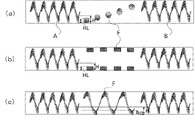
- FIG. 3 is a schematic diagram illustrating a batch firing process in the method for producing a positive electrode active material for lithium ion secondary batteries of the present invention.
- (a) shows an inclined charging stage
- (b) shows a horizontal firing stage
- (c) shows an inclined discharging stage.
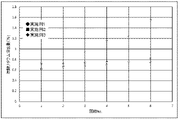
- FIG. 4 is a diagram showing changes in the elution amount of lithium carbonate in fired bodies according to Examples. It is a figure which shows the structural example of a lifter.
- a positive electrode active material according to an embodiment and a method for producing a positive electrode active material for a lithium ion secondary battery (hereinafter simply referred to as a method for producing a positive electrode active material) will be described, and then the batch firing process will be described.
- the mixed powder after moisture removal and before firing is called a precursor
- the precursor fired in a furnace is called a fired body
- the active material obtained after the entire firing process is called a lithium composite compound.
- the same reference numerals are given to components that are common in the following figures, and duplicate descriptions are omitted.
- the precursor charged inside is rolled and advanced to perform continuous firing.
- oxygen is flowed from the outlet side to the inlet side, but the concentration of carbon dioxide gas becomes higher on the inlet side and causes a concentration difference in the furnace. Due to the difference in carbon dioxide concentration, the amount of unreacted lithium carbonate increased, and as a result, the amount of lithium carbonate remaining in the fired body could not be reduced below the reference value. If it is attempted to reduce it below the standard, it is necessary to take a longer firing time, which is not preferable in terms of process steps.
- a rotary kiln is used in the second heat treatment step in which the reaction of the lithium compound is most promoted, that is, in the step of obtaining the fired body from the precursor.
- the precursor is put into the furnace, the precursor is concentrated and baked in the heating area, and the fired body is discharged. increase.
- the spiral blades on the supply side are provided from the inlet to the heating region, and the spiral blades on the discharge side are provided from the heating region to the outlet, the rotation of these spiral blades concentrates the precursor in the central heating region. easy.
- the height of the lifter (stirring blade) in the heating region is lower than the height of the supply side spiral blade and the discharge side spiral blade, the precursor in the heating region can be circulated in the axial direction within the heating region. Increases the efficiency of the reaction. Therefore, the sintered body in the high carbon dioxide concentration region can be moved to the low carbon dioxide concentration region, and all mixed powders can be sintered in the low carbon dioxide concentration region. As a result, unreacted lithium carbonate can be reduced, and the solid-phase reaction is uniformly promoted. Thereby, the amount of unreacted lithium carbonate can be effectively reduced, and productivity can be maintained.
- the positive electrode active material according to the present embodiment has an ⁇ -NaFeO 2 -type layered structure as a crystal structure, and is composed of a lithium composite oxide containing lithium and a transition metal (hereinafter referred to as a lithium composite compound). consists of
- the main phase of the positive electrode active material is a lithium composite compound having a layered structure.
- the positive electrode active material may contain lithium carbonate as an unavoidable impurity depending on manufacturing conditions, as described later. Lithium carbonate can exist in a state of forming a heterogeneous phase or in a state of adhering to the particles of the positive electrode active material.
- the positive electrode active material according to the present embodiment has the following formula (1) Li1 + aM1O2 + ⁇ (1) (However, in the above formula (1), M1 is a metal element other than Li and contains at least Ni, the proportion of Ni in M1 is 70 atomic% or more, a and ⁇ are -0.1 ⁇ a ⁇ 0.2, a number that satisfies ⁇ 0.2 ⁇ 0.2).
- the positive electrode active material according to the present embodiment has a composition in which the ratio of nickel (Ni) per metal element (M1) other than lithium (Li) is 70 atomic % or more, so that high energy density and high charge/discharge capacity can be achieved. It is a positive electrode active material that can be realized. Note that the proportion of nickel (Ni) per metal element (M1) other than lithium (Li) can take an appropriate value within the range of 70 atomic % or more and 100 atomic % or less. Since the positive electrode active material contains such a high proportion of nickel, it is important that the oxidation reaction for oxidizing Ni 2+ to Ni 3+ is efficiently carried out.
- the positive electrode active material represented by the above formula (2) has a high nickel content, it can exhibit higher charge/discharge capacity in the range up to around 4.3 V compared to LiCoO 2 or the like.
- the nickel content is high, the raw material cost is low compared to LiCoO 2 and the like, and the raw material is easily available.
- a is -0.1 or more and 0.2 or less.
- a may be -0.02 or more and 0.05 or less. If a is -0.02 or more, the amount of lithium sufficient to contribute to charge/discharge is ensured, so the charge/discharge capacity of the positive electrode active material can be increased. Further, when a is 0.05 or less, sufficient charge compensation due to the change in valence of the transition metal is achieved, so that both high charge-discharge capacity and good charge-discharge cycle characteristics can be achieved.
- the coefficient b of nickel is set to 0.7 or more and 1.0 or less.
- b is 0.7 or more, a sufficiently high charge/discharge capacity can be obtained as compared with the case of using other transition metals. Therefore, when b is within the above numerical range, a positive electrode active material exhibiting a high charge/discharge capacity can be produced at a lower cost than LiCoO 2 or the like.
- b is preferably 0.8 or more and 0.95 or less, more preferably 0.85 or more and 0.95 or less.
- b is 0.8 or more, the higher the charge/discharge capacity, the higher the charge/discharge capacity.
- the smaller b is 0.95 or less, the smaller the lattice distortion or crystal structure change accompanying the insertion or extraction of lithium ions, and the lower the cation mixing and crystallinity that nickel is mixed into the lithium site during firing. is less likely to occur, suppressing deterioration of charge/discharge capacity and charge/discharge cycle characteristics.
- the coefficient c of cobalt is 0 or more and 0.20 or less.
- the crystal structure is stabilized, and effects such as suppression of cation mixing in which nickel is mixed into lithium sites are obtained. Therefore, the charge/discharge cycle characteristics can be improved without significantly deteriorating the charge/discharge capacity.
- cobalt is excessive, the cost of raw materials will increase, which will increase the manufacturing cost of the positive electrode active material.
- c is within the above numerical range, both high charge/discharge capacity and good charge/discharge cycle characteristics can be achieved with good productivity.
- c may be 0.01 or more and 0.20 or less, or may be 0.03 or more and 0.20 or less.
- c 0.01 or more and is large, the effect of element substitution with cobalt is sufficiently obtained, and the charge-discharge cycle characteristics are further improved.
- c 0.20 or less, raw material cost becomes more inexpensive, and the productivity of the positive electrode active material becomes more favorable.
- the coefficient d of M shall be 0 or more and 0.20 or less.
- the layered structure is more stably maintained even if lithium is desorbed by charging.
- these elements (M) are excessive, the proportion of other transition metals such as nickel will be low, and the charge/discharge capacity of the positive electrode active material will be low.
- d is within the above numerical range, the crystal structure of the positive electrode active material can be stably maintained, and high charge/discharge capacity, good charge/discharge cycle characteristics, thermal stability, and the like can be obtained.
- Manganese and aluminum are preferable as the element represented by M. Such elements contribute to stabilizing the crystal structure of cathode materials with high nickel content. Among them, manganese is particularly preferred. When manganese is element-substituted, a higher charge-discharge capacity can be obtained than when aluminum is element-substituted. Manganese also reacts with lithium carbonate as shown in the following formula (3) during firing of the lithium composite compound. Such a reaction suppresses the coarsening of crystal grains and allows the oxidation reaction of nickel to proceed at high temperature, so that it is possible to efficiently obtain a positive electrode active material exhibiting a high charge/discharge capacity.
- M' represents a metal element such as Ni, Co, Mn.
- the coefficient d of M is preferably 0.02 or more, more preferably 0.04 or more.
- the coefficient d of M is preferably 0.18 or less. If the coefficient d of M is 0.18 or less, the charge/discharge capacity can be kept high even with element substitution.
- the coefficient e of X shall be 0 or more and 0.20 or less.
- X represents one or more metal elements other than Li, Ni, Co, Al and Mn, and is substituted with at least one element selected from the group consisting of magnesium, titanium, zirconium, molybdenum and niobium. With this, various performances such as charge-discharge cycle characteristics can be improved while maintaining the activity of the positive electrode active material. On the other hand, if these elements (X) are excessive, the ratio of other transition metals such as nickel will decrease, and the charge/discharge capacity of the positive electrode active material will decrease. When e is within the above numerical range, both high charge/discharge capacity and good charge/discharge cycle characteristics can be achieved.
- ⁇ in the formulas (1) and (2) should be ⁇ 0.2 or more and 0.2 or less.
- the positive electrode active material described above can be manufactured according to a general method for manufacturing a positive electrode active material, such as a solid phase method, a coprecipitation method, a sol-gel method, a hydrothermal method, or the like.
- a general method for manufacturing a positive electrode active material such as a solid phase method, a coprecipitation method, a sol-gel method, a hydrothermal method, or the like.
- the present invention is based on a method of synthesizing by a solid-phase method using a lithium compound as a raw material.
- compounds containing lithium include lithium carbonate, lithium acetate, lithium nitrate, lithium hydroxide, lithium chloride, lithium sulfate, and the like.
- lithium carbonate it is preferable to use lithium carbonate, and it is more preferable to use lithium carbonate at a rate of 80% by mass or more in the raw material containing lithium.
- Lithium carbonate is more stable in supply and cheaper than other lithium-containing compounds, and is readily available.
- lithium carbonate since lithium carbonate is weakly alkaline, it causes little damage to manufacturing equipment and is excellent in industrial applicability and practicality. A manufacturing method using lithium carbonate will be described below.
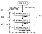
- FIG. 1 is a flow diagram showing an example of a method for producing a positive electrode active material according to one embodiment of the present invention.
- the method for producing a positive electrode active material according to this embodiment includes a mixing step S1 and a baking step S2. Through these steps, the lithium complex compounds represented by the formulas (1) and (2) are synthesized. In the following, the composition formula (2) will be described as an example.
- lithium carbonate and a compound containing a metal element other than Li in the formula (2) are mixed. That is, lithium carbonate and a nickel compound containing nickel are mixed as raw materials for the positive electrode active material. Further, when the lithium complex compound represented by the formula (2) contains cobalt, an element represented by M, or an element represented by X, a compound containing these elements is added and mixed. .
- the mixing step S1 at least lithium carbonate is used as the raw material containing lithium. As described above, it is inexpensive, readily available, and less likely to damage the manufacturing apparatus, which is preferable. In addition, since lithium carbonate has a relatively high melting point, it is possible to avoid formation of a liquid phase and coarsening of crystal grains during synthesis by a solid-phase method.
- nickel compounds such as nickel hydroxide, nickel carbonate, nickel oxide, nickel sulfate, and nickel acetate can be used as raw materials containing nickel.
- the nickel compound among these, it is particularly preferable to use nickel hydroxide, nickel carbonate, or nickel oxide.
- cobalt compounds containing cobalt, metal compounds containing the element represented by M, and metal compounds containing the element represented by X include nitrates, carbonates, sulfates, acetates, oxides, Hydroxide or the like can be used. Among these, it is particularly preferable to use carbonates, oxides, or hydroxides.
- raw materials such as lithium carbonate are weighed, pulverized and mixed to obtain a powdery mixed powder.
- a pulverizer for pulverizing raw materials for example, general precision pulverizers such as ball mills, jet mills and sand mills can be used.
- the pulverization of the raw material may be either dry pulverization or wet pulverization.
- the raw material slurry obtained by wet pulverization can be dried using various dryers such as a spray dryer, a fluidized bed dryer, and an evaporator.
- the raw material such as lithium carbonate is preferably pulverized to an average particle size of 0.5 ⁇ m or less. It is more preferable to pulverize to 2 ⁇ m or less.
- the raw material is pulverized to such a fine particle size, the reactivity between lithium carbonate and the nickel compound or the like is improved, and components such as carbon dioxide are easily desorbed from the raw material such as lithium carbonate.
- the degree of mixing of the pulverized material is increased, sintering tends to proceed uniformly, and the average particle size of the primary particles of the lithium composite compound can be easily controlled within an appropriate range.
- the mixing step S1 it is preferable to prepare slurry by mixing by wet pulverization and granulate the obtained slurry by spray drying.
- Raw materials such as lithium carbonate are mixed by wet pulverization in a medium such as water, and the resulting slurry is granulated by spray drying. After firing, the average particle size of the secondary particles is controlled, and the aspect ratio is close to 1 can be stably obtained.
- Various systems such as a two-fluid nozzle system, a four-fluid nozzle system, and a disk system can be used as the spray dryer.
- the average particle size of the secondary particles granulated by spray drying is preferably 5 ⁇ m or more and 25 ⁇ m or less, more preferably 5 ⁇ m or more and 20 ⁇ m or less.
- the average particle size of the secondary particles can be controlled by adjusting, for example, the concentration of the slurry, the viscosity of the slurry, the spray amount of the slurry, the dispersity of the suspended solids, the spray temperature, the spray pressure, the blowing speed, and the like.
- the mixed powder before sintering obtained through the mixing step S1 is sintered to obtain the lithium composite compound represented by the formula (2).
- the mixed powder that has undergone appropriate treatment such as spray granulation through the mixing step S1 is sintered under predetermined conditions to form a lithium composite compound having a layered structure.
- the firing step S2 may be performed by a single heat treatment in which the heat treatment temperature is controlled within a certain range, or may be performed by a plurality of heat treatments in which the heat treatment temperatures are controlled within different ranges.
- the firing step S2 preferably includes a first heat treatment step S21, a second heat treatment step S22, and a third heat treatment step S23.
- the particle size of the lithium composite compound is grown to an appropriate range by adjusting the heat treatment temperature, heat treatment time, atmosphere, etc., and carbonic acid remaining in the lithium composite compound at the end of firing is reduced. Since the amount of lithium can be greatly reduced, both high charge/discharge capacity and good charge/discharge cycle characteristics can be achieved.
- the mixed powder obtained in the mixing step S1 is heat treated at a heat treatment temperature of 200° C. or more and 500° C. or less for 0.5 hours or more and 5 hours or less to obtain a precursor. obtain.
- the primary purpose of the first heat treatment step S21 is to remove moisture and the like that hinder the synthesis reaction of the lithium complex compound from the mixed powder obtained in the mixing step S1.
- the first heat treatment step can be replaced with other conditions as long as the step can achieve this purpose.
- the first heat treatment step can be optionally performed.
- the heat treatment temperature is 200° C. or higher, the combustion reaction of impurities and the thermal decomposition of the raw material will proceed sufficiently, so that the formation of inert heterogeneous phases in the subsequent heat treatment is suppressed. be able to.
- the heat treatment temperature is 500° C. or less, crystals of the lithium composite compound are hardly formed in this step, so a crystal phase with low purity is formed in the presence of a gas containing moisture, impurities, etc. can prevent
- the heat treatment temperature in the first heat treatment step S21 is preferably 250°C or higher and 400°C or lower, and more preferably 250°C or higher and 380°C or lower. If the heat treatment temperature is within this range, it is possible to efficiently remove moisture, impurities, etc., and to reliably prevent the formation of crystals of the lithium complex compound in this step.
- the heat treatment time in the first heat treatment step S21 is appropriately determined according to, for example, the heat treatment temperature, the amount of moisture, impurities, etc. contained in the mixed powder, the target for removing moisture, impurities, etc., the degree of crystallization, etc. can be the time of
- the first heat treatment step S21 is preferably carried out under an atmospheric gas stream or under evacuation by a pump.
- gases containing moisture, impurities, and the like can be efficiently removed.
- the air flow rate of the atmosphere gas and the exhaust amount per hour by the pump be larger than the volume of the gas generated from the mixed powder.
- the volume of the gas generated from the powder mixture can be determined based on, for example, the amount of raw material used, the molar ratio of components gasified by combustion or thermal decomposition per raw material, and the like.
- the first heat treatment step S21 may be performed in an oxidizing gas atmosphere, a non-oxidizing gas atmosphere, or a reduced pressure atmosphere.
- the oxidizing gas atmosphere may be either an oxygen gas atmosphere or an air atmosphere.
- the reduced pressure atmosphere may be a reduced pressure condition with an appropriate degree of vacuum such as atmospheric pressure or less.
- the precursor obtained in the first heat treatment step S21 is heat treated at a heat treatment temperature of 600° C. or more and less than 750° C. for 10 hours or more and 100 hours or less to obtain a fired body.
- the main purpose of the second heat treatment step S22 is to remove the carbonic acid component by reacting lithium carbonate with a nickel compound or the like, oxidize nickel from divalent to trivalent, and generate crystals of a lithium composite compound. is performed as
- the second heat treatment step S22 95% by mass or more of lithium carbonate charged as a raw material is reacted. It is preferable to react 97% by mass or more, more preferably 98% by mass or more. If the reaction of lithium carbonate is insufficient and the oxidation of nickel is insufficient, bivalent nickel is likely to be substituted with lithium sites, which may reduce the charge/discharge capacity of the positive electrode active material. Further, if a large amount of lithium carbonate remains at the end of the second heat treatment step S22, carbon dioxide is released into the atmosphere of the third heat treatment step S23, which inhibits the reaction for forming crystals, or the carbonate component becomes lithium.
- lithium carbonate may melt and form a liquid phase in the third heat treatment step S23.
- the crystal grains become coarse, which may deteriorate the output characteristics of the lithium ion secondary battery.
- the liquid phase is less likely to occur in the third heat treatment step S23. become difficult to convert. Therefore, while ensuring the output characteristics of the lithium ion secondary battery, nickel can be oxidized at a high temperature, and a lithium composite compound exhibiting a high charge/discharge capacity can be fired.
- the heat treatment temperature is 600° C. or higher, the formation of a layered structure proceeds due to the reaction between the lithium carbonate and the nickel compound or the like, so it is possible to prevent unreacted lithium carbonate from remaining. can. Therefore, it becomes difficult for lithium carbonate to form a liquid phase in the subsequent heat treatment, grain coarsening is suppressed, and a positive electrode active material exhibiting high particle breaking strength and charge/discharge capacity can be obtained. Also, if the heat treatment temperature is less than 750° C., grain growth does not proceed excessively, so the charge/discharge capacity of the positive electrode active material increases.
- the heat treatment temperature in the second heat treatment step S22 is preferably 650°C or higher.
- the higher the heat treatment temperature the more the reaction of lithium carbonate is promoted, and the more reliably the lithium carbonate is prevented from remaining.
- the coefficient d of manganese exceeds 0 and is less than 0.075, it is preferable to set the temperature to 600 ° C. or higher. .
- the coefficient d of manganese is 0.075 or higher, the reaction temperature is lowered, so the temperature should be 550° C. or higher.
- the heat treatment temperature in the second heat treatment step S22 is preferably 700°C or lower, more preferably 680°C or lower.
- the heat treatment time in the second heat treatment step S22 is preferably 10 hours or more and 50 hours or less, more preferably 20 hours or more and 30 hours or less.
- the heat treatment time is within this range, the reaction of lithium carbonate proceeds sufficiently, so that the carbonic acid component can be reliably removed.
- the time required for the heat treatment is shortened, and the productivity of the positive electrode active material is improved.
- the second heat treatment step S22 is preferably performed in an oxidizing atmosphere.
- the oxygen concentration in the atmosphere is preferably 80% or higher, more preferably 90% or higher, still more preferably 95% or higher, and particularly preferably 100%.
- the carbon dioxide concentration in the atmosphere is preferably 5% or less, more preferably 1% or less, and even more preferably 0.1% or less.
- the second heat treatment step S22 is preferably performed under an oxidizing gas stream. If the heat treatment is carried out under an oxidizing gas stream, the nickel can be reliably oxidized and the carbon dioxide released into the atmosphere can be reliably eliminated.
- the second heat treatment step S22 may be performed multiple times as a calcining step.
- the sintered body obtained in the second heat treatment step S22 is heat treated at a heat treatment temperature of 750° C. or more and 900° C. or less for 0.5 hours or more and 50 hours or less to produce a lithium composite. to obtain the compound.
- the main purpose of the third heat treatment step S23 is to sufficiently oxidize the nickel in the fired body from divalent to trivalent and to grow the crystal grains of the lithium composite compound having a layered structure to an appropriate size. done.
- the nickel can be sufficiently oxidized and the primary particles can be grown to an appropriate particle size, so the crystallinity is high and the open pore volume ratio is high.
- a lithium composite compound with a low is fired. Therefore, the amount of lithium carbonate remaining during firing and the amount of lithium carbonate mixed in after firing are reduced, and a positive electrode active material with high charge/discharge capacity can be obtained.
- the heat treatment temperature is 900° C. or less, lithium is difficult to volatilize, and the decomposition of the lithium composite compound having a layered structure is suppressed, so the purity of the crystals obtained after firing is lowered and the charge-discharge capacity is lowered. can be avoided.
- the heat treatment temperature in the third heat treatment step S23 is preferably 800°C or higher, more preferably 840°C or higher, and even more preferably 850°C or higher. The higher the heat treatment temperature, the more surely nickel is oxidized, and the grain growth of the lithium composite compound can be promoted.
- the heat treatment temperature in the third heat treatment step S23 is preferably 890°C or less.
- the heat treatment time in the third heat treatment step S23 is preferably 0.5 hours or more and 15 hours or less.
- the heat treatment time is within this range, it is possible to sufficiently oxidize nickel and obtain a lithium composite compound with high crystal purity and high charge-discharge capacity. Moreover, the time required for the heat treatment is shortened, and the productivity of the positive electrode active material is improved.
- the third heat treatment step S23 is preferably performed in an oxidizing atmosphere.
- the oxygen concentration in the atmosphere is preferably 80% or higher, more preferably 90% or higher, still more preferably 95% or higher, and particularly preferably 100%.
- the carbon dioxide concentration in the atmosphere is preferably 5% or less, more preferably 1% or less, and even more preferably 0.1% or less.
- the third heat treatment step S23 is preferably performed under an oxidizing gas stream. If the heat treatment is carried out under an oxidizing gas stream, the nickel can be reliably oxidized and the carbon dioxide released into the atmosphere can be reliably removed.
- the third heat treatment step S23 is preferably performed once as the main firing step, but may be performed multiple times.
- the lithium composite compound represented by the formula (2) is obtained.
- the lithium composite compound may be classified as necessary so that the secondary particles have an appropriate average particle size.
- a suitable heating device such as a rotary furnace such as a rotary kiln, a roller hearth kiln, a tunnel furnace, a continuous furnace such as a pusher furnace, or a batch furnace can be used.
- the first heat treatment step S21, the second heat treatment step S22, and the third heat treatment step S23 may be performed using the same heating device, or may be performed using different heating devices. Further, each heat treatment step may be performed intermittently by changing the atmosphere, or may be performed continuously when the heat treatment is performed while exhausting the gas in the atmosphere.
- the firing step of the second heat treatment step S22 is performed using a rotary furnace such as a rotary kiln. A batch firing process using a rotary kiln will be described below.
- the rotary kiln has a rotatable and tiltable furnace core tube, an inlet for supplying the precursor, and an outlet for discharging the sintered body after heat treatment.
- powder is advanced while being rolled by rotation of an inclined furnace core tube for firing.
- a rotary kiln employs a batch system in which a holding time for the sintered body is ensured, and charging and discharging operations are separately performed. This is called a batch sintering process in the present invention. In this firing process, as shown in FIG.
- step (a) in which the furnace is placed in an inclined state and the precursor is charged into the heating region
- step (a) in which the furnace is placed in a horizontal state and the precursor is charged into the heating region in the furnace. It consists of a horizontal firing stage (b) in which the fired body is uniformly fired while maintaining the time, and an inclined discharging stage (c) in which the fired body in which the firing reaction has progressed is discharged by tilting the furnace.
- the precursor (mixed powder) is charged into the core tube of the rotary kiln.
- a heating area in the central part of the furnace, and a discharge side spiral blade is provided from the central part to the outlet of the furnace, and a supply side spiral blade is provided to the inlet of the furnace.
- Spiral grooves in opposite directions are cut in the spiral blade and the discharge-side spiral blade.
- the spiral groove rotates in the opposite direction, and the powder placed on the spiral groove can be moved in the opposite direction.
- the charged precursor can be collected in the central heating area of the furnace, that is, moved to the heating area and concentrated.
- the furnace core tube In the horizontal firing stage, the furnace core tube is placed in a horizontal state with an inclination angle of 0 degrees, and the furnace core tube is rotated forward at a rotation speed of about 1 to 3 rpm, and heating and firing is started.
- the rotation direction of the furnace core tube is the forward rotation direction and the rotation speed is about 1 rpm
- the firing time is about 15 to 50 hours, so that the precursor is rolled and the fired body is kept in the heating area. Firing can proceed.
- the inclination angle of the furnace core tube is changed to, for example, 3 degrees, and the rotation directions of the discharge side spiral blade and the supply side spiral blade are reversed from forward rotation. Change the direction of rotation. As a result, the spiral grooves are rotated in opposite directions, and the sintered body in the furnace is moved to the outlet side by the discharge-side spiral blades and discharged.
- the inclination angle of the rotary kiln can be, for example, about 1 to 5 degrees, preferably 2 to 3 degrees. can. At this time, the rotation speed can also be increased.
- the supply-side spiral blade and the discharge-side spiral blade are formed with opposite spiral grooves.
- FIG. FIG. 4(a) is an example in which cylindrical protrusions are arranged in a spiral shape
- (b) is an example in which columnar protrusions are arranged in the axial direction and radial direction
- (c) is an example in which the cylindrical protrusions are arranged in the shape of a spiral blade.
- the height HL of the lifter F is lower than the height H of the blades in the outer region.
- the blades in the area other than the heating area need to keep the sintered powder in the heating area, so the spiral blades on the supply side and the discharge side outside the heating area are higher than the filling height of the sintered powder. should be suppressed from leaking out of the heating area.
- a lifter stir blade
- the lifter does not need to be high, but rather has a shape that is easy to scrape up in small increments, so that the precursor in the heating area can be sintered while being circulated in the longitudinal direction within the heating area.
- the oxygen concentration in the heating area is higher on the discharge side than on the supply side, so if there is no circulation, the fired powder will always be fired with a difference in oxygen concentration even within the heating area. As a result, it is easy to produce a sintered body in which the degree of progress of the solid-phase reaction differs between the sintered powder on the supply side and the sintered powder on the discharge side.
- the sintered body in the low oxygen concentration area can be moved to the high oxygen concentration area, and all the mixed powder is sintered in the high oxygen concentration (low carbon dioxide concentration) area. it becomes possible to As a result, unreacted lithium carbonate can be reduced.
- the lifter in the heating area may be formed continuously and integrally with the supply-side spiral blade and/or the discharge-side spiral blade, or may be formed separately.
- the height should be about 1/3 to 2/3 of the filling height of the sintered powder.
- the shape of the lifter may be any shape as long as it is easy to rake up and circulate.
- Example 1 As starting materials for the positive electrode active material, lithium carbonate, nickel hydroxide, cobalt carbonate, manganese carbonate, and titanium oxide were prepared. These starting materials are weighed so that the atomic ratio of Li:Ni:Co:Mn:Ti is 1.04:0.85:0.03:0.10:0.02, and the mixing step S1 is performed. did. Specifically, ion-exchanged water was added and mixed so that the total weight of the starting materials was 20 mass %, and the mixture was pulverized and mixed with a bead mill to obtain a pulverized powder having an average particle size of 0.16 ⁇ m. The obtained solid-liquid mixture was dried using a spray dryer to obtain a raw material mixed powder having an average particle size of 11.6 ⁇ m.
- the obtained raw material mixed powder is filled in an alumina sintering container, and heat-treated at 360° C. for 1 hour in an air atmosphere by a roller hearth kiln (first heat treatment step S21) to obtain a precursor (mixture). Obtained.
- first heat treatment step S21 not only the moisture absorbed by the raw material mixed powder is removed, but also the nickel hydroxide is thermally decomposed and each carbonate is partially thermally decomposed to remove a certain amount of carbon dioxide gas.
- the spiral blades are attached along the inner peripheral surface of the core tube, and the supply side spiral blade B and the discharge side spiral blade A consist of spiral blades wound in opposite directions.
- the spiral blades on the supply (intake) side and the discharge (outlet) side move the precursor to the heating region D.
- the height of the spiral blades in the regions other than the heating region is set to be higher than the height of the sintered powder filling in order to keep the sintered body in the heating region D, and on the other hand, the sintered body in the heating region is The height of the lifter F installed in the heating area for circulation is lower than the spiral blades on the supply side and the discharge side, and about half the height of the other parts. Since the blades of different heights are provided in the heating area and the other areas, the sintered body in the heating area can circulate within the heating area (horizontal sintering stage).
- the furnace core tube was tilted at an inclination angle of 3 degrees, the rotation speed was 3 rpm, and the rotation direction of the furnace core tube was reversed, and the fired precursor (that is, the fired body) E was discharged (inclined discharge stage).
- the spiral blade B on the supply side moves the sintered material toward the inlet side
- the spiral vane A on the discharge side moves the sintered material toward the outlet side.
- the first discharged powder is the sintered body on the outlet side of the heating area
- the last discharged powder is the sintered body on the intake side of the heating area. Therefore, the unevenness of firing in the furnace during batch operation can be observed by dividing and recovering. The results are also shown in FIG.
- the obtained sintered body is subjected to heat treatment at 840° C. for 10 hours in an oxidizing atmosphere with an oxygen concentration of 95% or more (third heat treatment step S23) to produce Li 1.0 Ni 0
- a sintered powder of a lithium composite compound having a composition of .85 Co 0.03 Mn 0.10 Ti 0.02 O 2 was obtained.
- the obtained baked powder of the lithium composite compound was classified to a mesh size of 45 ⁇ m or less to obtain a positive electrode active material.
- Table 1 shows the elution amount of lithium carbonate from the sintered body obtained by batch sintering treatment in Example 1 and the reaction rate of lithium carbonate, and FIG. Table 1 shows the elution amount of lithium carbonate from the positive electrode active material (lithium composite compound). The measuring method will be described below.
- Example 2 A sintered body was obtained in the same manner as in Example 1, except that a rotary kiln without a lifter in the heating region was used in the second heat treatment step and the holding time was set to 30 hours.
- the precursor was charged at a filling rate of 30%, and the operation was performed at 700° C. for 30 hours in an oxidizing atmosphere with an oxygen concentration of 95% or more. After that, all the sintered bodies in the furnace were discharged. Also at this time, when the second heat treatment step was completed, the fired body was divided and collected in the same manner as in Example 1, and the eluted amount of lithium carbonate in each fired body was measured. The results are also shown in FIG.
- Example 1 the elution amount and reaction rate of lithium carbonate in the fired body were measured. Table 1 shows the results.
- a positive electrode active material was obtained in the same manner as in Example 1 using the fired body.
- the amount of lithium carbonate eluted from this positive electrode active material was measured in the same manner as in Example 1. The results are shown in Table 1.
- Example 3 A sintered body was obtained in the same manner as in Example 2, except that the operation time of the second heat treatment step was 18 hours. Also at this time, the fired body was divided and recovered in the same manner as in Example 1, and the eluted amount of lithium carbonate in each fired body was measured. The results are also shown in FIG. Further, in the same manner as in Example 1, the elution amount and reaction rate of lithium carbonate in the fired body were measured. Table 1 shows the results. Next, a positive electrode active material was obtained in the same manner as in Example 1 using the fired body. The amount of lithium carbonate eluted from this positive electrode active material was measured in the same manner as in Example 1. The results are shown in Table 1.
- Example 1 Same as Example 1 except that the starting materials were weighed so that the atomic ratio of Li:Ni:Co:Mn:Ti was 1.04:0.90:0.03:0.05:0.02.
- a raw material mixed powder was prepared and subjected to the first heat treatment.
- the second heat treatment step was carried out using a continuously operating rotary kiln in which the raw material powder was continuously fed and passed through a heating zone with the core tube rotating at 1 rpm and tilted at an inclination angle of 1 degree.
- a fired body was obtained in the same manner as in Example 1 except for the above.
- the charging rate in continuous operation was 120 g/hr (equivalent to a filling rate of 3%).
- the continuous operation type is a method in which the precursor is supplied while the furnace core tube is inclined, the precursor is sintered while being rolled, and the sintered body is continuously discharged. However, in the second heat treatment step, the fired body adhered to the inner wall and could not be discharged.
- Comparative Example 2 Heat treatment was performed in the same manner as in Comparative Example 1, except that the heat treatment temperature in the second heat treatment step was 650°C. Incidentally, in Comparative Example 2, the sintered body could be recovered. Here, in the case of continuous operation, the holding time was 1 hour per passage through the rotary kiln once, and the heat treatment was carried out for 5 hours by passing through the rotary kiln a total of 5 times. In the same manner as in Example 1, the sintered body was recovered by dividing the weight corresponding to 10% of the total charged amount, and the lithium carbonate elution amount of the obtained sintered body was measured. Further, the reaction rate was calculated from the results. Table 1 shows the results.
- the amount of lithium carbonate eluted from the fired body or the positive electrode active material was measured by neutralization titration using an automatic titrator "COM-1700A" (manufactured by Hiranuma Sangyo Co., Ltd.). First, 0.5 g of the positive electrode active material was dispersed in 30 mL of pure water bubbled with argon gas. After the dispersion was stirred for 60 minutes, the filtrate was collected by suction filtration and titrated with hydrochloric acid.
- the titration curve has two stages, up to the first equivalence point corresponds to the total amount of hydroxide ions of lithium hydroxide and carbonate ions of lithium carbonate, and from the first equivalence point to the second equivalence point It corresponds to the amount of bicarbonate ions generated from carbonate ions. Therefore, the amount of lithium carbonate (% by mass) was calculated from the titration amount from the first equivalence point to the second equivalence point.
- reaction rate of lithium carbonate The reaction rate was calculated based on the following formula (4).
- Reaction rate (%) [(L1-L2) ⁇ L1] x 100 (4)
- a positive electrode and a lithium ion secondary battery were produced using the positive electrode active material obtained in the example, and the discharge capacity of the lithium ion secondary battery was evaluated.
- the positive electrode active material could not be recovered, and in Comparative Example 2, although it was recovered, the reaction was insufficient, so evaluation was not performed.
- a positive electrode active material, a binder, and a conductive material were mixed to prepare a positive electrode mixture slurry.
- the prepared positive electrode mixture slurry was applied to a current collector made of aluminum foil with a thickness of 20 ⁇ m and dried at 120° C. to form a positive electrode mixture layer, and the electrode density was 2.6 g/cm 3 . It was compression-molded by a press so as to have a diameter of 15 mm, and was punched out into a disk shape with a diameter of 15 mm to prepare a positive electrode.
- a negative electrode was produced using metallic lithium as a negative electrode active material.
- a lithium ion secondary battery was produced using the produced positive electrode and negative electrode.
- the non-aqueous electrolyte a solution was used in which LiPF 6 was dissolved to a concentration of 1.0 mol/L in a mixed solvent of ethylene carbonate and dimethyl carbonate at a volume ratio of 3:7. .
- charging was performed with a charging current of 0.2 CA at a constant current and constant voltage until the charging end voltage (4.3 V), and discharging was performed with a discharging current of 0.2 CA.
- the discharge capacity was measured by constant current up to the final discharge voltage (3.3 V or 2.5 V).
- Example 1 the elution amount of lithium carbonate varies little due to the action of the spiral blades.
- Example 2 by lowering the height of the lifter (spiral blade) in the heating area, it became possible to effectively circulate the fired body in the heating area.
- the sintered body in the high carbon dioxide concentration region was sintered only in the high carbon dioxide concentration region during sintering. It was possible to advance the reaction by touching the gas of high concentration.
- Example 1 all powder properties obtained are excellent, so it can be said that a sintered body having excellent powder properties can be efficiently obtained.
- Example 2 the reaction was able to proceed by taking a longer firing time.
- Example 3 the retention time is as short as 18 hours compared to Example 2 (30 hours). However, there is also variation in the amount of lithium carbonate eluted, suggesting that the baking time is insufficient, and it can be said that the amount of lithium carbonate between collection lots will be uniform by increasing the retention time from 18 hours to 30 hours. .
- the reaction rate of lithium carbonate can be increased in the second heat treatment step, and variations in the amount of elution can be suppressed. Then, the discharge capacity of the positive electrode active material obtained in the third heat treatment step was increased. This is because the elution amount of lithium carbonate could be reduced in the second heat treatment step, that is, the reaction rate of lithium carbonate could be improved. Therefore, grain growth is further suppressed, and as a result, it is considered that the charge/discharge capacity of the positive electrode active material is increased.
- the recovery rate decreased and the amount of lithium carbonate eluted increased.
- the sintered body was no longer discharged in the second heat treatment step. This is because the viscosity of the powder increases around the melting point of lithium carbonate, and the powder with the increased viscosity is operated at a low rotation speed and a low tilt angle, causing adhesion of the powder. Once adhesion occurs, it is difficult for the powder to pass over the step due to the mass of the adhesion, and the adhesion increases, which is considered to be the dead end. It has been confirmed that even with a high rotational speed and a high tilt angle, it becomes difficult to secure the firing time in the heating region, and the solid-phase reaction cannot proceed.
- S1 mixing step
- S2 baking step
- S21 first heat treatment step
- S22 second heat treatment step
- S23 third heat treatment step
- A discharge side spiral blade
- B supply side spiral blade
- C precursor to be introduced
- D fired body
- E discharged fired body
- F lifter
Landscapes
- Chemical & Material Sciences (AREA)
- Inorganic Chemistry (AREA)
- Engineering & Computer Science (AREA)
- Organic Chemistry (AREA)
- Chemical Kinetics & Catalysis (AREA)
- Electrochemistry (AREA)
- General Chemical & Material Sciences (AREA)
- Mechanical Engineering (AREA)
- General Engineering & Computer Science (AREA)
- Materials Engineering (AREA)
- Manufacturing & Machinery (AREA)
- Battery Electrode And Active Subsutance (AREA)
Abstract
Description
特許文献2では、リチウム複合酸化物の前駆体(粉体)をロータリーキルン内で転動させながら焼成するものであって、筒状炉の正逆回転方向を交互に切り替えることで、前駆体の昇温と降温を繰り返し、もって前駆体の温度を均一にして焼成を行うリチウムイオン二次電池用正極活物質の製造方法が開示されている。
特許文献3では、リチウム複合酸化物の前駆体をロータリーキルン内で転動させながら焼成するものであって、筒状炉内で前進する前駆体に酸化性ガスを吹き付けると共に、前駆体から発生する炭酸ガスを酸化性ガスの気流で排気しながら焼成を行うリチウムイオン二次電池用正極活物質の製造方法が開示されている。
また、特許文献4では、炉心管内に羽根が設けられ、炉心管と羽根が回転することにより、粉の転動と、羽根の衝撃とで付着現象の抑制をしながら焼成を行うリチウムイオン二次電池用正極活物質の製造方法が開示されている。
Li1+aM1O2+α ・・・(1)
(但し、前記式(1)中、M1は、Li以外の金属元素であって少なくともNiを含み、M1における前記Niの割合が70原子%以上、a及びαは、-0.1≦a≦0.2、-0.2≦α≦0.2、を満たす数である。)
また、前記取入口から加熱領域入口まで供給側らせん羽根を備え、加熱領域内にはリフターを備え、また、加熱領域出口から前記取出口にかけて排出側らせん羽根を備えており、前記供給側らせん羽根および/または前記排出側らせん羽根の高さよりも前記リフターの高さが低いことにより、前記加熱領域にある前駆体を循環させながら焼成することを特徴とするものである。
Li1+aNibCocMdXeO2+α ・・・(2)
[但し、組成式(2)において、Mは、Al及びMnから選ばれる少なくとも1種を表し、XはLi、Ni、Co、Al及びMn以外の1種以上の金属元素を表し、a、b、c、d、e及びαは、それぞれ、-0.1≦a≦0.2、0.7≦b≦1.0、0≦c≦0.20、0≦d≦0.20、0≦e≦0.20、b+c+d+e=1、及び、-0.2<α<0.2を満たす数である。]
本実施形態に係る正極活物質は、結晶構造としてα-NaFeO2型の層状構造を有し、リチウムと遷移金属とを含んで組成されるリチウム複合酸化物(以下、リチウム複合化合物と言う。)からなる。正極活物質の主相は、層状構造を有するリチウム複合化合物である。但し、正極活物質は、後記するように、製造条件に依存して、炭酸リチウムを不可避的不純物として含み得る。炭酸リチウムは、異相を形成した状態や、正極活物質の粒子に付着した状態で存在し得る。
Li1+aM1O2+α ・・・(1)
(但し、前記式(1)中、M1は、Li以外の金属元素であって少なくともNiを含み、M1における前記Niの割合が70原子%以上、a及びαは、-0.1≦a≦0.2、-0.2≦α≦0.2、を満たす数である。)で表される。
Li1+aNibCocMdXeO2+α ・・・(2)
[但し、組成式(2)において、Mは、Al及びMnから選ばれる少なくとも1種を表し、XはLi、Ni、Co、Al及びMn以外の1種以上の金属元素を表し、a、b、c、d、e及びαは、それぞれ、-0.1≦a≦0.2、0.7≦b≦1.0、0≦c≦0.20、0≦d≦0.20、0≦e≦0.2、b+c+d+e=1、及び、-0.2<α<0.2を満たす数である。]で表される。
(但し、前記式(3)中、M´は、Ni、Co、Mn等の金属元素を表す。)
次に、正極活物質の製造方法について説明する。前記した正極活物質は、例えば、固相法、共沈法、ゾルゲル法、水熱法等の一般的な正極活物質の製造方法に準じて製造することができるものである。本発明は、これらの方法の中でも、リチウム化合物を原料として用いて固相法で合成する方法によるものである。リチウムを含む化合物としては、例えば、炭酸リチウム、酢酸リチウム、硝酸リチウム、水酸化リチウム、塩化リチウム、硫酸リチウム等が挙げられる。中でも炭酸リチウムを用いることが好ましく、リチウムを含む原料中、炭酸リチウムを80質量%以上の割合で用いることがより好ましい。炭酸リチウムは、リチウムを含む他の化合物と比較して供給安定性に優れ、安価であるため、容易に入手することができる。また、炭酸リチウムは、弱アルカリ性であるため、製造装置へのダメージが少なく、工業利用性や実用性に優れている。以下では炭酸リチウムを用いた製造方法を説明する。
ロータリーキルンは、回転と傾斜が可能な炉心管と、前駆体を供給する取入口と、熱処理後の焼成体を排出する取出口とを有している。通常、ロータリーキルンでは、傾斜した炉心管が回転することにより粉体を転動させながら前進させて焼成を行っている。本発明では、焼成体の保持時間の確保と投入、排出作業を別々に行うバッチ式をロータリーキルンで採用したもので、これを本発明では、バッチ焼成処理過程と呼んでいる。この焼成過程には、図2で示すように、炉を傾斜状態として前駆体を加熱領域に投入する傾斜投入段階(a)と、炉を水平状態として、炉内の加熱領域に前駆体を長時間保持しながら均等に焼成する水平焼成段階(b)と、炉を傾斜状態として、焼成反応の進んだ焼成体を排出する傾斜排出段階(c)からなる。
焼成時、加熱領域における酸素濃度は供給側より排出側が高くなっているので、循環がない場合だと加熱領域内でも焼成粉は常に酸素濃度に差がついた状態で焼成される。その結果、供給側と排出側の焼成粉において固相反応の進行度が異なる焼成体ができ易い。一方で循環がある場合は、酸素濃度が低い領域にある焼成体を酸素濃度が高い領域へ移動させることができ、全ての混合粉体を酸素濃度が高い(炭酸ガス濃度の低い)領域で焼成することが可能になる。その結果、未反応の炭酸リチウムが低減できる。
正極活物質の出発原料として、炭酸リチウム、水酸化ニッケル、炭酸コバルト、炭酸マンガン、酸化チタンを用意した。これら出発原料を、原子比でLi:Ni:Co:Mn:Tiが、1.04:0.85:0.03:0.10:0.02となるように秤量し、混合工程S1を実施した。具体的には、出発原料の総重量が20mass%となるようにイオン交換水を加えて混合し、ビーズミルにて粉砕混合を実施し、平均粒径0.16μmの粉砕粉とした。得られた固液混合物は、スプレードライヤを用いて乾燥し、平均粒径は11.6μmの原料混合粉を得た。
第2熱処理工程に、加熱領域にリフターが無いロータリーキルンを用いた点、及び保持時間を30時間とした点以外は実施例1と同様にして焼成体を得た。尚、バッチ運転では、充填率30%相当の前駆体を投入して酸素濃度95%以上の酸化性雰囲気で700℃、30時間運転した。その後、炉内の焼成体を全て排出させた。このときも第2熱処理工程が終了した際、実施例1と同様に焼成体を分割して回収し、それぞれの焼成体の炭酸リチウムの溶出量を測定した。その結果を図3に併記して示す。また、実施例1と同様にして焼成体の炭酸リチウムの溶出量と反応率を測定した。結果を表1に示す。
次に、上記焼成体を用いて実施例1と同様にして正極活物質を得た。この正極活物質の炭酸リチウムの溶出量を実施例1と同様にして測定した。この結果を表1に示す。
第2熱処理工程の運転時間を18時間実施した以外は実施例2と同様にして焼成体を得た。このときも焼成体を実施例1と同様に分割回収して、それぞれの焼成体の炭酸リチウムの溶出量を測定した。その結果を図3に併記して示す。また、実施例1と同様にして焼成体の炭酸リチウムの溶出量と反応率を測定した。結果を表1に示す。
次に、上記焼成体を用いて実施例1と同様にして正極活物質を得た。この正極活物質の炭酸リチウムの溶出量を実施例1と同様にして測定した。この結果を表1に示す。
出発原料を、原子比でLi:Ni:Co:Mn:Tiが、1.04:0.90:0.03:0.05:0.02となるように秤量した以外は実施例1と同様に原料混合粉を作製し、第1熱処理を施した。第2熱処理工程を、炉心管の回転数1rpm、傾斜角1度で傾斜させた状態で連続的に原料粉末を供給して加熱帯を通過させる、連続運転式のロータリーキルンを用いて実施した。それ以外は実施例1と同様にして焼成体を得た。連続運転での投入速度は120g/hr(充填率3%相当)で実施した。尚、連続運転式は炉心管を傾斜させた状態で前駆体の供給を行い、そのまま転動させながら前進させて焼成し、焼成体の排出を連続的に行う方式である。しかし、第2熱処理工程において焼成体が内壁に付着して焼成体を排出することが出来なかった。
第2熱処理工程の熱処理温度を650℃とした以外は比較例1と同様に熱処理を行なった。尚、比較例2では焼成体を回収できた。ここで連続運転の場合は、ロータリーキルン1回の通過で保持時間が1時間となり、合計5回通過させて5時間相当の熱処理を実施した。焼成体の回収は実施例1と同様に投入総量の10%相当重量ずつ分割回収し、得られた焼成体の炭酸リチウム溶出量を測定した。更にその結果から反応率を算出した。結果を表1に示す。低温化により付着は回避できたものの、炭酸リチウム溶出量が多く、反応率は95%未満であった。また、連続式のロータリーキルンで第3熱処理工程を実施したところ、炭酸リチウムの溶出量は0.40%と多く、十分に炭酸リチウムを反応させることが出来なかった。
焼成体あるいは正極活物質から溶出する炭酸リチウムの量を自動滴定装置「COM-1700A」(平沼産業社製)を用いて中和滴定によって測定した。はじめに、アルゴンガスでバブリングした30mLの純水中に0.5gの正極活物質を分散させた。そして、分散液を60分間にわたって攪拌した後、吸引濾過により濾液を回収し、その濾液を塩酸で滴定した。滴定曲線は2段階となり、第一等量点までが水酸化リチウムの水酸化物イオンと炭酸リチウムの炭酸イオンの合計量に対応しており、第一等量点から第二等量点までが炭酸イオンから生成した炭酸水素イオンの量に対応している。そのため、第一等量点から第二等量点までの滴定量から炭酸リチウムの量(質量%)を算出した。
反応率については下記式(4)に基づき算出した。
反応率(%)=[(L1-L2)÷ L1]×100・・・(4)
L1:第1熱処理後(前駆体)の炭酸リチウム溶出量
L2:第2熱処理後(焼成体)の炭酸リチウム溶出量
次に、実施例で得られた正極活物質を用いて正極及びリチウムイオン二次電池を作製し、リチウムイオン二次電池の放電容量を評価した。尚、比較例1では正極活物質を回収できず、比較例2では回収できたものの反応が不十分であったため評価は行っていない。
はじめに、正極活物質と、結着剤と、導電材とを混合し、正極合剤スラリーを調製した。そして、調製した正極合剤スラリーを、厚さ20μmのアルミ箔からなる集電体に塗布し、120℃で乾燥させて正極合剤層を形成した後、電極密度が2.6g/cm3となるようにプレスで圧縮成形し、直径15mmの円盤状に打ち抜いて正極を作製した。
また、図3に、実施例1、実施例2、実施例3の焼成体における炭酸リチウムの溶出量の推移を示した。


A:排出側らせん羽根、B:供給側らせん羽根、C:投入する前駆体、D:焼成体、E:排出した焼成体、F:リフター
Claims (6)
- リチウム化合物と下記式(1)中のLi以外の金属元素を含む化合物とを混合して混合粉体を得る混合工程と、
前記混合粉体を熱処理して前駆体を得る第1熱処理工程と、前記前駆体を熱処理して焼成体を得る第2熱処理工程と、前記焼成体を熱処理して下記式(1)で表されるリチウム複合化合物を得る第3熱処理工程と、を有し、
前記第2熱処理工程には、
前記前駆体を炉心管内の加熱領域で転動させつつ加熱を行うバッチ焼成処理過程を有しており、
前記バッチ焼成処理過程において、
前記炉心管を傾けて、前記焼成炉の取入口から前駆体を投入する傾斜投入段階と、
前記炉心管を水平となして、焼成する水平焼成段階と、
前記炉心管を傾けて、前記焼成炉の取出口から焼成体を排出する傾斜排出段階と、
を有することでリチウム化合物の95質量%以上を反応させることを特徴とするリチウムイオン二次電池用正極活物質の製造方法。
Li1+aM1O2+α ・・・(1)
(但し、前記式(1)中、M1は、Li以外の金属元素であって少なくともNiを含み、M1における前記Niの割合が70原子%以上、a及びαは、-0.1≦a≦0.2、-0.2≦α≦0.2、を満たす数である。) - 前記炉心管は、前記取入口から前記加熱領域にかけて供給側らせん羽根を備え、また、前記加熱領域から前記取出口にかけて排出側らせん羽根を備えており、前記バッチ焼成処理過程において、前記加熱領域に前駆体を集約することを特徴とする請求項1に記載のリチウムイオン二次電池用正極活物質の製造方法。
- 前記取入口から加熱領域入口まで供給側らせん羽根を備え、加熱領域内にはリフターを備え、また、加熱領域出口から前記取出口にかけて排出側らせん羽根を備えており、前記供給側らせん羽根および/または前記排出側らせん羽根の高さよりも前記リフターの高さが低いことにより、前記加熱領域にある前駆体を循環させながら焼成することを特徴とする請求項1または請求項2に記載のリチウムイオン二次電池用正極活物質の製造方法。
- 前記加熱領域にあるリフターがらせん状の羽根であることを特徴とする請求項3に記載のリチウムイオン二次電池用正極活物質の製造方法。
- 前記傾斜投入段階および/または前記傾斜排出段階での前記炉心管の回転数は、前記水平焼成段階における炉心管の回転数よりも高くする、ことを特徴とする請求項1から請求項4のいずれか一項に記載のリチウムイオン二次電池用正極活物質の製造方法。
- 前記組成式(1)は、下記組成式(2)で表され、
前記混合工程におけるスラリーの平均粒径を0.1μm以上0.5μm以下とし、
前記スラリーを造粒して得た造粒粉体の二次粒子の平均粒径を5μm以上20μm以下とし、
前記焼成工程は、
前記造粒粉体を200℃以上500℃以下の熱処理温度で0.5時間以上5時間以下に亘って熱処理して前駆体を得る第1熱処理工程を任意に有し、
前記前駆体を600℃以上750℃未満の熱処理温度で10時間以上100時間以下に亘って酸化性雰囲気下で熱処理して焼成体を得る第2熱処理工程と、
前記焼成体を750℃以上900℃以下の熱処理温度で0.5時間以上50時間以下に亘って酸化性雰囲気下で熱処理してリチウム複合化合物を得る第3熱処理工程と、を有することを特徴とする請求項1から請求項5のいずれか一項に記載のリチウムイオン二次電池用正極活物質の製造方法。
Li1+aNibCocMdXeO2+α ・・・(2)
[但し、組成式(2)において、Mは、Al及びMnから選ばれる少なくとも1種を表し、XはLi、Ni、Co、Al及びMn以外の1種以上の金属元素を表し、a、b、c、d、e及びαは、それぞれ、-0.1≦a≦0.2、0.7≦b≦1.0、0≦c≦0.20、0≦d≦0.20、0≦e≦0.20、b+c+d+e=1、及び、-0.2<α<0.2を満たす数である。]
Priority Applications (5)
| Application Number | Priority Date | Filing Date | Title |
|---|---|---|---|
| KR1020237028001A KR20230159692A (ko) | 2021-03-26 | 2022-02-22 | 리튬이온 이차전지용 정극 활물질의 제조방법 |
| JP2023508825A JP7683680B2 (ja) | 2021-03-26 | 2022-02-22 | リチウムイオン二次電池用正極活物質の製造方法 |
| US18/280,663 US20240300825A1 (en) | 2021-03-26 | 2022-02-22 | Method for manufacturing positive electrode active material for lithium ion secondary battery |
| CN202280020168.1A CN116998030A (zh) | 2021-03-26 | 2022-02-22 | 锂离子二次电池用正极活性物质的制造方法 |
| EP22774866.2A EP4317077A4 (en) | 2021-03-26 | 2022-02-22 | Method for manufacturing positive electrode active material for lithium ion secondary battery |
Applications Claiming Priority (2)
| Application Number | Priority Date | Filing Date | Title |
|---|---|---|---|
| JP2021-054392 | 2021-03-26 | ||
| JP2021054392 | 2021-03-26 |
Publications (1)
| Publication Number | Publication Date |
|---|---|
| WO2022202066A1 true WO2022202066A1 (ja) | 2022-09-29 |
Family
ID=83396998
Family Applications (1)
| Application Number | Title | Priority Date | Filing Date |
|---|---|---|---|
| PCT/JP2022/007418 Ceased WO2022202066A1 (ja) | 2021-03-26 | 2022-02-22 | リチウムイオン二次電池用正極活物質の製造方法 |
Country Status (6)
| Country | Link |
|---|---|
| US (1) | US20240300825A1 (ja) |
| EP (1) | EP4317077A4 (ja) |
| JP (1) | JP7683680B2 (ja) |
| KR (1) | KR20230159692A (ja) |
| CN (1) | CN116998030A (ja) |
| WO (1) | WO2022202066A1 (ja) |
Citations (9)
| Publication number | Priority date | Publication date | Assignee | Title |
|---|---|---|---|---|
| JPH11139829A (ja) | 1997-11-04 | 1999-05-25 | Nikki Chemcal Co Ltd | リチウムイオン二次電池用正極材の製造方法 |
| JPH11255541A (ja) * | 1997-12-11 | 1999-09-21 | Asea Brown Boveri Ag | 材料、特にスラグ又はガラスを発泡させるための方法と装置 |
| JP2002277166A (ja) | 2001-03-23 | 2002-09-25 | Takasago Ind Co Ltd | バッチ式ロータリーキルン |
| JP2005067972A (ja) * | 2003-08-26 | 2005-03-17 | Met:Kk | 炭化賦活方法及び炭化賦活装置 |
| WO2009098835A1 (ja) | 2008-02-04 | 2009-08-13 | Panasonic Corporation | リチウム含有遷移金属酸化物の製造方法 |
| JP2013155989A (ja) * | 2012-01-31 | 2013-08-15 | Shigeru Yoshida | バッチ式ロータリーキルン及びバッチ式ロータリーキルンによる加熱処理方法 |
| WO2017213002A1 (ja) | 2016-06-09 | 2017-12-14 | 日立金属株式会社 | リチウム二次電池用正極活物質の製造方法 |
| JP2019160801A (ja) * | 2018-03-07 | 2019-09-19 | 日立金属株式会社 | リチウムイオン二次電池用正極活物質及びリチウムイオン二次電池 |
| JP2021153028A (ja) * | 2020-03-25 | 2021-09-30 | 日立金属株式会社 | リチウムイオン二次電池用正極活物質の製造方法 |
Family Cites Families (10)
| Publication number | Priority date | Publication date | Assignee | Title |
|---|---|---|---|---|
| JP5292761B2 (ja) | 2007-10-16 | 2013-09-18 | 沖電気工業株式会社 | 紙幣分離集積機構 |
| JP6485232B2 (ja) * | 2014-11-27 | 2019-03-20 | 日立金属株式会社 | 正極活物質の製造方法 |
| US20160156020A1 (en) * | 2014-11-27 | 2016-06-02 | Hitachi Metals, Ltd. | Method for manufacturing cathode electrode materials |
| JP6268342B2 (ja) | 2016-04-27 | 2018-01-31 | 株式会社ジェイテックコーポレーション | 大量細胞培養システム及びそれに用いる回転細胞培養装置 |
| JP6970885B2 (ja) * | 2017-10-16 | 2021-11-24 | 日立金属株式会社 | リチウム二次電池用正極活物質の製造方法 |
| JP6988402B2 (ja) * | 2017-11-21 | 2022-01-05 | 日立金属株式会社 | リチウムイオン二次電池用正極活物質の製造方法及び熱処理装置 |
| KR102387062B1 (ko) * | 2017-11-21 | 2022-04-15 | 히타치 긴조쿠 가부시키가이샤 | 리튬 이온 이차 전지용 정극 활물질의 제조 방법 및 열처리 장치 |
| WO2019131779A1 (ja) * | 2017-12-27 | 2019-07-04 | 日立金属株式会社 | リチウムイオン二次電池用正極活物質及びリチウムイオン二次電池用正極活物質の製造方法、並びにリチウムイオン二次電池 |
| KR102713885B1 (ko) * | 2018-03-07 | 2024-10-08 | 가부시키가이샤 프로테리아루 | 리튬 이온 이차 전지용 정극 활물질 및 리튬 이온 이차 전지 |
| WO2020195790A1 (ja) * | 2019-03-25 | 2020-10-01 | 日立金属株式会社 | リチウムイオン二次電池用正極活物質、及びその製造方法、並びにリチウムイオン二次電池 |
-
2022
- 2022-02-22 WO PCT/JP2022/007418 patent/WO2022202066A1/ja not_active Ceased
- 2022-02-22 US US18/280,663 patent/US20240300825A1/en active Pending
- 2022-02-22 EP EP22774866.2A patent/EP4317077A4/en active Pending
- 2022-02-22 KR KR1020237028001A patent/KR20230159692A/ko active Pending
- 2022-02-22 CN CN202280020168.1A patent/CN116998030A/zh active Pending
- 2022-02-22 JP JP2023508825A patent/JP7683680B2/ja active Active
Patent Citations (9)
| Publication number | Priority date | Publication date | Assignee | Title |
|---|---|---|---|---|
| JPH11139829A (ja) | 1997-11-04 | 1999-05-25 | Nikki Chemcal Co Ltd | リチウムイオン二次電池用正極材の製造方法 |
| JPH11255541A (ja) * | 1997-12-11 | 1999-09-21 | Asea Brown Boveri Ag | 材料、特にスラグ又はガラスを発泡させるための方法と装置 |
| JP2002277166A (ja) | 2001-03-23 | 2002-09-25 | Takasago Ind Co Ltd | バッチ式ロータリーキルン |
| JP2005067972A (ja) * | 2003-08-26 | 2005-03-17 | Met:Kk | 炭化賦活方法及び炭化賦活装置 |
| WO2009098835A1 (ja) | 2008-02-04 | 2009-08-13 | Panasonic Corporation | リチウム含有遷移金属酸化物の製造方法 |
| JP2013155989A (ja) * | 2012-01-31 | 2013-08-15 | Shigeru Yoshida | バッチ式ロータリーキルン及びバッチ式ロータリーキルンによる加熱処理方法 |
| WO2017213002A1 (ja) | 2016-06-09 | 2017-12-14 | 日立金属株式会社 | リチウム二次電池用正極活物質の製造方法 |
| JP2019160801A (ja) * | 2018-03-07 | 2019-09-19 | 日立金属株式会社 | リチウムイオン二次電池用正極活物質及びリチウムイオン二次電池 |
| JP2021153028A (ja) * | 2020-03-25 | 2021-09-30 | 日立金属株式会社 | リチウムイオン二次電池用正極活物質の製造方法 |
Non-Patent Citations (1)
| Title |
|---|
| See also references of EP4317077A4 |
Also Published As
| Publication number | Publication date |
|---|---|
| US20240300825A1 (en) | 2024-09-12 |
| EP4317077A1 (en) | 2024-02-07 |
| CN116998030A (zh) | 2023-11-03 |
| JP7683680B2 (ja) | 2025-05-27 |
| JPWO2022202066A1 (ja) | 2022-09-29 |
| EP4317077A4 (en) | 2025-02-19 |
| KR20230159692A (ko) | 2023-11-21 |
Similar Documents
| Publication | Publication Date | Title |
|---|---|---|
| JP6579237B2 (ja) | リチウム二次電池用正極活物質の製造方法 | |
| JP5808316B2 (ja) | リチウムイオン電池用正極活物質の製造方法 | |
| TWI513663B (zh) | Production method of positive electrode active material for lithium ion battery and positive electrode active material for lithium ion battery | |
| TWI468367B (zh) | Production method of positive electrode active material for lithium ion battery and positive electrode active material for lithium ion battery | |
| JP6970885B2 (ja) | リチウム二次電池用正極活物質の製造方法 | |
| JP7618991B2 (ja) | リチウムイオン二次電池用正極活物質、及びその製造方法、並びにリチウムイオン二次電池 | |
| JP7532880B2 (ja) | リチウムイオン二次電池用正極活物質、及びその製造方法、並びにリチウムイオン二次電池 | |
| JP7464102B2 (ja) | 金属複合水酸化物とその製造方法、非水電解質二次電池用正極活物質とその製造方法、及び、それを用いた非水電解質二次電池 | |
| JP2025143333A (ja) | リチウム二次電池用正極活物質の製造方法 | |
| JP7683680B2 (ja) | リチウムイオン二次電池用正極活物質の製造方法 | |
| JP2021153028A (ja) | リチウムイオン二次電池用正極活物質の製造方法 | |
| JP7318842B1 (ja) | リチウムイオン二次電池用正極活物質およびリチウムイオン二次電池 | |
| JPH11111290A (ja) | リチウム二次電池用正極材料及びその製造方法 | |
| JP7473713B2 (ja) | リチウムコバルト系複合酸化物粒子及びその製造方法、リチウムコバルト系複合酸化物粒子組成物及びそれらの製造方法 | |
| JP7340995B2 (ja) | 固体電解質用の鎖状チタン酸ランタンリチウム結晶粒子集合体の製造方法 | |
| US20230030652A1 (en) | Process for preparing lithium transition metal oxides | |
| KR100550373B1 (ko) | 2차전지전극으로서사용하기위한Li1+xMn2-xO4의제조방법 | |
| CN120440970A (zh) | 一种羟基氧化铁锰前驱体的制备方法、磷酸铁锰锂/碳复合材料及其制备方法 | |
| JPH10194746A (ja) | リチウムマンガン複合酸化物の製造方法並びにその用途 |
Legal Events
| Date | Code | Title | Description |
|---|---|---|---|
| 121 | Ep: the epo has been informed by wipo that ep was designated in this application |
Ref document number: 22774866 Country of ref document: EP Kind code of ref document: A1 |
|
| WWE | Wipo information: entry into national phase |
Ref document number: 18280663 Country of ref document: US |
|
| WWE | Wipo information: entry into national phase |
Ref document number: 202280020168.1 Country of ref document: CN |
|
| WWE | Wipo information: entry into national phase |
Ref document number: 2022774866 Country of ref document: EP |
|
| NENP | Non-entry into the national phase |
Ref country code: DE |
|
| ENP | Entry into the national phase |
Ref document number: 2022774866 Country of ref document: EP Effective date: 20231026 |
|
| WWE | Wipo information: entry into national phase |
Ref document number: 2023508825 Country of ref document: JP |