WO2022202182A1 - フォトクロミックレンズの製造方法、フォトクロミックレンズ - Google Patents
フォトクロミックレンズの製造方法、フォトクロミックレンズ Download PDFInfo
- Publication number
- WO2022202182A1 WO2022202182A1 PCT/JP2022/009072 JP2022009072W WO2022202182A1 WO 2022202182 A1 WO2022202182 A1 WO 2022202182A1 JP 2022009072 W JP2022009072 W JP 2022009072W WO 2022202182 A1 WO2022202182 A1 WO 2022202182A1
- Authority
- WO
- WIPO (PCT)
- Prior art keywords
- photochromic
- compound
- resin substrate
- substrate
- gap
- Prior art date
- Legal status (The legal status is an assumption and is not a legal conclusion. Google has not performed a legal analysis and makes no representation as to the accuracy of the status listed.)
- Ceased
Links
Images


Classifications
-
- B—PERFORMING OPERATIONS; TRANSPORTING
- B29—WORKING OF PLASTICS; WORKING OF SUBSTANCES IN A PLASTIC STATE IN GENERAL
- B29D—PRODUCING PARTICULAR ARTICLES FROM PLASTICS OR FROM SUBSTANCES IN A PLASTIC STATE
- B29D11/00—Producing optical elements, e.g. lenses or prisms
- B29D11/00009—Production of simple or compound lenses
- B29D11/0048—Moulds for lenses
- B29D11/00538—Feeding arrangements
-
- B—PERFORMING OPERATIONS; TRANSPORTING
- B29—WORKING OF PLASTICS; WORKING OF SUBSTANCES IN A PLASTIC STATE IN GENERAL
- B29C—SHAPING OR JOINING OF PLASTICS; SHAPING OF MATERIAL IN A PLASTIC STATE, NOT OTHERWISE PROVIDED FOR; AFTER-TREATMENT OF THE SHAPED PRODUCTS, e.g. REPAIRING
- B29C39/00—Shaping by casting, i.e. introducing the moulding material into a mould or between confining surfaces without significant moulding pressure; Apparatus therefor
- B29C39/22—Component parts, details or accessories; Auxiliary operations
- B29C39/24—Feeding the material into the mould
-
- B—PERFORMING OPERATIONS; TRANSPORTING
- B29—WORKING OF PLASTICS; WORKING OF SUBSTANCES IN A PLASTIC STATE IN GENERAL
- B29C—SHAPING OR JOINING OF PLASTICS; SHAPING OF MATERIAL IN A PLASTIC STATE, NOT OTHERWISE PROVIDED FOR; AFTER-TREATMENT OF THE SHAPED PRODUCTS, e.g. REPAIRING
- B29C45/00—Injection moulding, i.e. forcing the required volume of moulding material through a nozzle into a closed mould; Apparatus therefor
- B29C45/0001—Injection moulding, i.e. forcing the required volume of moulding material through a nozzle into a closed mould; Apparatus therefor characterised by the choice of material
-
- B—PERFORMING OPERATIONS; TRANSPORTING
- B29—WORKING OF PLASTICS; WORKING OF SUBSTANCES IN A PLASTIC STATE IN GENERAL
- B29C—SHAPING OR JOINING OF PLASTICS; SHAPING OF MATERIAL IN A PLASTIC STATE, NOT OTHERWISE PROVIDED FOR; AFTER-TREATMENT OF THE SHAPED PRODUCTS, e.g. REPAIRING
- B29C45/00—Injection moulding, i.e. forcing the required volume of moulding material through a nozzle into a closed mould; Apparatus therefor
- B29C45/03—Injection moulding apparatus
-
- B—PERFORMING OPERATIONS; TRANSPORTING
- B29—WORKING OF PLASTICS; WORKING OF SUBSTANCES IN A PLASTIC STATE IN GENERAL
- B29D—PRODUCING PARTICULAR ARTICLES FROM PLASTICS OR FROM SUBSTANCES IN A PLASTIC STATE
- B29D11/00—Producing optical elements, e.g. lenses or prisms
- B29D11/00009—Production of simple or compound lenses
-
- B—PERFORMING OPERATIONS; TRANSPORTING
- B29—WORKING OF PLASTICS; WORKING OF SUBSTANCES IN A PLASTIC STATE IN GENERAL
- B29D—PRODUCING PARTICULAR ARTICLES FROM PLASTICS OR FROM SUBSTANCES IN A PLASTIC STATE
- B29D11/00—Producing optical elements, e.g. lenses or prisms
- B29D11/00009—Production of simple or compound lenses
- B29D11/00413—Production of simple or compound lenses made by moulding between two mould parts which are not in direct contact with one another, e.g. comprising a seal between or on the edges
-
- B—PERFORMING OPERATIONS; TRANSPORTING
- B29—WORKING OF PLASTICS; WORKING OF SUBSTANCES IN A PLASTIC STATE IN GENERAL
- B29D—PRODUCING PARTICULAR ARTICLES FROM PLASTICS OR FROM SUBSTANCES IN A PLASTIC STATE
- B29D11/00—Producing optical elements, e.g. lenses or prisms
- B29D11/00009—Production of simple or compound lenses
- B29D11/0048—Moulds for lenses
- B29D11/00528—Consisting of two mould halves joined by an annular gasket
-
- B—PERFORMING OPERATIONS; TRANSPORTING
- B29—WORKING OF PLASTICS; WORKING OF SUBSTANCES IN A PLASTIC STATE IN GENERAL
- B29D—PRODUCING PARTICULAR ARTICLES FROM PLASTICS OR FROM SUBSTANCES IN A PLASTIC STATE
- B29D11/00—Producing optical elements, e.g. lenses or prisms
- B29D11/00634—Production of filters
- B29D11/00653—Production of filters photochromic
-
- B—PERFORMING OPERATIONS; TRANSPORTING
- B29—WORKING OF PLASTICS; WORKING OF SUBSTANCES IN A PLASTIC STATE IN GENERAL
- B29D—PRODUCING PARTICULAR ARTICLES FROM PLASTICS OR FROM SUBSTANCES IN A PLASTIC STATE
- B29D11/00—Producing optical elements, e.g. lenses or prisms
- B29D11/0073—Optical laminates
-
- G—PHYSICS
- G02—OPTICS
- G02B—OPTICAL ELEMENTS, SYSTEMS OR APPARATUS
- G02B1/00—Optical elements characterised by the material of which they are made; Optical coatings for optical elements
- G02B1/04—Optical elements characterised by the material of which they are made; Optical coatings for optical elements made of organic materials, e.g. plastics
- G02B1/041—Lenses
-
- G—PHYSICS
- G02—OPTICS
- G02B—OPTICAL ELEMENTS, SYSTEMS OR APPARATUS
- G02B3/00—Simple or compound lenses
- G02B3/12—Fluid-filled or evacuated lenses
-
- G—PHYSICS
- G02—OPTICS
- G02B—OPTICAL ELEMENTS, SYSTEMS OR APPARATUS
- G02B5/00—Optical elements other than lenses
- G02B5/20—Filters
- G02B5/22—Absorbing filters
- G02B5/23—Photochromic filters
-
- G—PHYSICS
- G02—OPTICS
- G02C—SPECTACLES; SUNGLASSES OR GOGGLES INSOFAR AS THEY HAVE THE SAME FEATURES AS SPECTACLES; CONTACT LENSES
- G02C7/00—Optical parts
- G02C7/10—Filters, e.g. for facilitating adaptation of the eyes to the dark; Sunglasses
- G02C7/102—Photochromic filters
-
- G—PHYSICS
- G03—PHOTOGRAPHY; CINEMATOGRAPHY; ANALOGOUS TECHNIQUES USING WAVES OTHER THAN OPTICAL WAVES; ELECTROGRAPHY; HOLOGRAPHY
- G03F—PHOTOMECHANICAL PRODUCTION OF TEXTURED OR PATTERNED SURFACES, e.g. FOR PRINTING, FOR PROCESSING OF SEMICONDUCTOR DEVICES; MATERIALS THEREFOR; ORIGINALS THEREFOR; APPARATUS SPECIALLY ADAPTED THEREFOR
- G03F7/00—Photomechanical, e.g. photolithographic, production of textured or patterned surfaces, e.g. printing surfaces; Materials therefor, e.g. comprising photoresists; Apparatus specially adapted therefor
- G03F7/004—Photosensitive materials
- G03F7/0045—Photosensitive materials with organic non-macromolecular light-sensitive compounds not otherwise provided for, e.g. dissolution inhibitors
-
- B—PERFORMING OPERATIONS; TRANSPORTING
- B29—WORKING OF PLASTICS; WORKING OF SUBSTANCES IN A PLASTIC STATE IN GENERAL
- B29C—SHAPING OR JOINING OF PLASTICS; SHAPING OF MATERIAL IN A PLASTIC STATE, NOT OTHERWISE PROVIDED FOR; AFTER-TREATMENT OF THE SHAPED PRODUCTS, e.g. REPAIRING
- B29C2945/00—Indexing scheme relating to injection moulding, i.e. forcing the required volume of moulding material through a nozzle into a closed mould
- B29C2945/76—Measuring, controlling or regulating
- B29C2945/76003—Measured parameter
- B29C2945/761—Dimensions, e.g. thickness
-
- B—PERFORMING OPERATIONS; TRANSPORTING
- B29—WORKING OF PLASTICS; WORKING OF SUBSTANCES IN A PLASTIC STATE IN GENERAL
- B29D—PRODUCING PARTICULAR ARTICLES FROM PLASTICS OR FROM SUBSTANCES IN A PLASTIC STATE
- B29D11/00—Producing optical elements, e.g. lenses or prisms
- B29D11/00865—Applying coatings; tinting; colouring
-
- B—PERFORMING OPERATIONS; TRANSPORTING
- B29—WORKING OF PLASTICS; WORKING OF SUBSTANCES IN A PLASTIC STATE IN GENERAL
- B29L—INDEXING SCHEME ASSOCIATED WITH SUBCLASS B29C, RELATING TO PARTICULAR ARTICLES
- B29L2011/00—Optical elements, e.g. lenses, prisms
- B29L2011/0016—Lenses
Definitions
- the present invention relates to a photochromic lens manufacturing method and a photochromic lens.
- Examples of the method of polymerizing a composition containing a polymerizable compound to obtain a molded product include casting polymerization and the like.
- an injection molding apparatus is provided with means for injecting the composition into the space between the two mold substrates by fixing the peripheral edges of the two mold substrates with a fixing member while facing each other. Used. Then, a molding is obtained by a method of injecting the composition into the space and then polymerizing and curing the composition.
- Patent Document 1 As a method for producing a plastic lens, there is an in-mass method (Patent Document 1) in which a photochromic lens is produced by adding a photochromic compound to a plastic lens substrate, and a plastic lens substrate to which no photochromic compound is added is coated with a photochromic compound.
- Patent Document 2 A coating method (Patent Document 2) in which a photochromic lens is produced by coating with Further, Patent Document 3 discloses a method for manufacturing a molded body using a predetermined mold.
- a photochromic lens needs to have a predetermined amount of photochromic compound present on the side of the object plane that receives light in order to exhibit its effect.
- the photochromic lens obtained by the in-mass method described in Patent Document 1 since a composition based on the concentration of the photochromic compound required on the object side is used, the total amount of the photochromic compound in the entire lens is large. In some cases, initial coloring was observed.
- Patent Literature 3 does not specifically disclose a method for producing a photochromic lens, and does not suggest problems when using a photochromic compound.
- the photochromic lens As a result of intensive studies by the present inventors, according to a predetermined manufacturing method, it is possible to make the photochromic lens into a two-layer structure and to make the layer on the objective side containing the photochromic compound have a predetermined thickness.
- the photochromic compound can be contained in an appropriate concentration only in the layer on the surface side, and the resulting photochromic lens has a suppressed initial coloration and excellent photochromic responsiveness, and has completed the present invention. . That is, the present invention can be shown below.
- a substantially circular substrate a substantially circular resin substrate arranged to face the surface of the substrate; a fixing member that fixes the peripheral edge of the substrate and the peripheral edge of the resin substrate; a gap formed between the substrate and the resin substrate and having a width of 0.1 to 2.5 mm in the thickness direction of the central portion of the substantially circle; an injection part provided in the fixing member for injecting a polymerizable composition into the gap; a space formed in at least a part of the periphery of the gap and communicating with the injection part and the gap; A method for manufacturing a photochromic lens using an injection molding apparatus, wherein the space is formed in at least a part of the peripheral edge of the resin substrate, and the width of the space in the thickness direction is larger than the width of the gap in the thickness direction.
- the method for producing a photochromic lens according to any one of [1] to [6], which includes the step of exposing to the end face of the body.
- the photochromic compound is a naphthopyran compound.
- the "initial stage” means a state in which the photochromic compound has not developed color without being irradiated with light.
- the present invention it is possible to provide a method for manufacturing a photochromic lens that suppresses initial coloring and provides a photochromic lens that is excellent in photochromic responsiveness.
- FIG. 1 is a schematic cross-sectional view schematically showing the injection molding apparatus of the first embodiment.
- FIG. 2 is a schematic plan view schematically showing the injection molding apparatus of the first embodiment.
- FIG. 3 is an enlarged sectional view schematically showing another aspect of the space section in the injection molding apparatus of the first embodiment.
- FIG. 4 is an enlarged sectional view schematically showing another aspect of the space section in the injection molding apparatus of the first embodiment.
- FIG. 5 is an enlarged sectional view schematically showing another aspect of the space section in the injection molding apparatus of the first embodiment.
- FIG. 6 is a schematic cross-sectional view schematically showing the injection molding apparatus of the second embodiment.
- FIG. 7 is a schematic cross-sectional view of the laminated lens (laminate) of this embodiment.
- the method for producing a photochromic lens of the present invention comprises: a substantially circular substrate; a substantially circular resin substrate arranged to face a surface of the substrate; a peripheral edge portion of the substrate; a fixing member that fixes a peripheral edge portion of the resin substrate; and the resin substrate, the gap having a width of 0.1 to 2.5 mm in the thickness direction of the center of the circle, and the polymerizable composition in the gap provided in the fixing member and a space formed in at least a part of the periphery of the gap and communicating the injection part and the gap, wherein the space is at least part of the periphery of the resin substrate.
- the polymerizable composition containing an isocyanate compound, a thiol compound, a polyol compound, and a photochromic compound is injected from the injection part, and the polymerizable composition is injected into the gap through the space. filling; a step of heating and polymerizing and curing the filled polymerizable composition to form a photochromic layer (photochromic compound-containing layer) on the resin substrate; a step of taking out the obtained laminate composed of the resin substrate and the photochromic layer; including.
- a photochromic layer having a predetermined layer thickness can be laminated on a resin substrate, initial coloring is suppressed, and photochromic responsiveness is achieved.
- a photochromic lens excellent in the polymerizable composition can be uniformly filled in the gap formed between the substrate and the resin substrate, producing a photochromic lens with an excellent appearance in which the inclusion of air bubbles and the generation of striae are suppressed. can do.
- the injection molding apparatus 10 of this embodiment includes a substantially circular substrate 12 and a substantially circular resin substrate 14 arranged to face the surface 12a of the substrate 12. , a fixing member 16 for fixing the peripheral end portion of the substrate 12 and the peripheral end portion of the resin substrate 14, and the polymerizable composition is injected into the gap 20 provided in the fixing member 16 between the substrate 12 and the resin substrate 14. and an injection part 18 for.
- a space 22 is provided around the entire circumference of the gap 20 .
- a molded article can be obtained by polymerizing the polymerizable composition filled in the gap 20 .
- the substantially circular substrate 12 is not particularly limited as long as a molded body can be prepared within the gap 20, but can be made of, for example, glass, metal, resin, or the like.
- the substantially circular substrate 12 can be used as a mold substrate, and can also be a laminate of the substrate 12 and a thin-film molded body formed in the gap 20 .
- the substrate 12 has a surface 12 a facing the resin substrate 14 .
- the surface 12a can be used as a forming surface for forming an objective surface.
- the substantially circular resin substrate 14 is not particularly limited as long as a molded body can be prepared within the gap 20, but may be poly(thio)urethane, poly(thio)urethane urea, polysulfide (e.g., polyepisulfide, polyene-polythiol polymer). , polythioether, etc.), polyepoxide, polycarbonate, poly(meth)acrylate, ADC (allyl diglycol carbonate), polyolefin, cyclic polyolefin, ring-opening metathesis polymer, polyester, polysiloxane, polyamide, polyimide, etc. Can be configured.
- a laminate photochromic lens
- a laminate photochromic lens
- the resin substrate 14 is preferably made of polyepisulfide resin, polyurethane resin or polythiourethane resin, more preferably polyepisulfide resin or polythiourethane resin.
- the monomer component constituting the resin contained in the resin substrate 14 include the monomer component contained in the polymerizable composition described later, and these monomer components may be the same or different.
- the substantially circular resin substrate 14 has a surface 14a facing the surface 12a of the substrate 12, and the substrate 12 and the resin substrate 14 are curved in the same direction.
- the radius of curvature of the surface (curved surface) 12a and the surface (curved surface) 14a are approximately the same, and the width of the gap 20 between these surfaces in the thickness direction is approximately the same.
- the width of the gap 20 in the thickness direction is 0.1 mm to 2.5 mm, preferably 0.3 mm to 2.0 mm, more preferably 0.5 mm to 1.5 mm, particularly preferably 0.6 mm to 1.2 mm. .
- the lower limit of the width of the gap 20 in the thickness direction is 0.1 mm or more, preferably 0.3 mm or more, more preferably 0.5 mm or more, and particularly preferably 0.6 mm or more.
- the upper limit of the width of the gap 20 in the thickness direction is 2.5 mm or less, preferably 2.0 mm or less, more preferably 1.5 mm or less, and particularly preferably 1.2 mm or less.
- the width of the gap 20 in the thickness direction equal to or less than the above upper limit value, a photochromic layer having a predetermined layer thickness can be laminated on the resin substrate 14, and even if the concentration of the photochromic compound is increased, the initial It becomes easy to suppress the coloration of , and a photochromic lens excellent in photochromic responsiveness can be obtained.
- the gap 20 is a gap formed between the surface 14a of the resin substrate 14 and the surface 12a of the substrate 12 when they are arranged to face each other. At least a portion of the surface 14a of the resin substrate 14 and the surface 12a of the substrate 12 are arranged parallel to each other, so that the thickness of the photochromic layer obtained by the polymerizable composition filled in the gap 20 is uniform. can do.
- the width of the gap 20 in the thickness direction is intended to be the average of the shortest distances between the surfaces 14a and 12a and corresponds to the thickness of the subsequently obtained photochromic layer.
- the gap 20 is filled with the polymerizable composition through the space 22, so air bubbles are not mixed in the gap 20. It is possible to uniformly fill while suppressing , and to manufacture a photochromic lens excellent in appearance in which inclusion of air bubbles or the like is suppressed. Further, in the prior art, a photochromic layer was obtained by applying a polymerizable composition using a spin coating method or the like, so the photochromic compound concentration in the peripheral portion of the photochromic layer tended to increase. In contrast, in the present embodiment, the gap 20 can be uniformly filled with the polymerizable composition, so that uneven distribution of the photochromic compound can be reduced.
- the resin substrate 14 has a cutout portion 24 along the entire periphery thereof.
- the injection molding apparatus 10 has a space 22 surrounded by a notch 24 of the resin substrate 14, the substrate 12, and the fixing member 16.
- the width i of the space 22 in the thickness direction of the substrate is not particularly limited as long as it is larger than the width of the gap 20, and the upper limit can be appropriately changed depending on the thickness and strength of the resin substrate 14 and the like.
- the width i of the space 22 in the substrate diameter direction is preferably, for example, about 1 to 10 mm.
- the width ii of the space 22 in the diameter direction of the resin substrate 14 is Although not limited, it is preferably about 1 to 10 mm.
- the diameter iii of the resin substrate 14 is approximately 50 mm to 100 mm.
- the ratio (ii/iii) of the width ii of the space 22 in the board diameter direction to the diameter iii of the resin board 14 is more than 0 and not more than 0.27, preferably about 0.01 to 0.27.
- the space 22 communicates with the injection section 18 and the gap 20, and as shown in the schematic plan view of FIG. It is constructed so that it can be filled into the gap 20 by pressing. That is, as will be described later, the polymerizable composition of the present embodiment has a relatively high viscosity and thus tends to involve air bubbles during filling. Since the gap 20 is filled with the polymerizable composition through the space 22, the inclusion of air bubbles can be suppressed.
- the substrate 12 and the resin substrate 14 can be used as mold substrates.
- the substrate 12 since the laminate of the thin-film photochromic layer formed in the gap 20 and the resin substrate 14 is used as a photochromic lens, the substrate 12 has a formation surface (surface 12a) for forming an object plane. is provided on the resin substrate 14 side, and the concave surface of the resin substrate 14 can be used as the viewing surface.
- the fixing member 16 is not particularly limited as long as the surface 12a of the substrate 12 and the surface 14a of the resin substrate 14 can be arranged facing each other, but it can be made of tape, gasket, or the like. By winding the tape around the peripheral edge of the substrate 12 and the peripheral edge of the resin substrate 14, these positions can be fixed. Moreover, it is preferable that the surface 12a of the substrate 12 and the surface 14a of the resin substrate 14 are fixed so that at least a part of the area is parallel to each other.
- An injection part 18 (not shown) is provided in the fixing member 16 so that the polymerizable composition can be injected into the space 22 .
- Examples include openings and joints of injection devices.
- a polymerizable composition can be injected into the space 22 from the injection part 18, and injection means such as a pipette tip, a syringe, an automatic injection device, etc. can be connected to the injection part 18.
- the viscosity of the polymerizable composition used in this embodiment can be 5 to 1000 mPa ⁇ s, preferably 10 to 500 mPa ⁇ s.
- the viscosity of the polymerizable composition can be measured at 25° C. using a Brookfield viscometer.
- the injection molding apparatus 10 of the present embodiment can uniformly fill the gap 20 with the polymerizable composition through the space 22 even if the polymerizable composition has such a viscosity. It is possible to laminate a photochromic layer having a predetermined layer thickness on top, suppressing initial coloring, making it possible to obtain a photochromic lens with excellent photochromic responsiveness and suppressing the inclusion of air bubbles. A photochromic lens with excellent appearance can be manufactured.
- FIG. 1 shows an example in which the space 22 is surrounded by the notch 24 of the resin substrate 14, the substrate 12, and the fixing member 16.
- a U-shaped groove may be provided, and the space 22 may be formed by the groove formed in the resin substrate 14 and the substrate 12 .
- the surface 12a of the substrate 12 is concave and the surface 14a of the resin substrate 14 is convex, but the surface 12a may be convex and the surface 14a may be concave.
- the resin substrate 14 may be a resin lens having curved surfaces on both sides, a resin lens having only a curved surface 14a, or a flat resin plate having both sides flat. The same applies to other embodiments.
- the space 22 is provided along the entire circumference of the resin substrate 14 , but as shown in FIG. It may be provided, and may be provided to any selected position within approximately half the circumference (1/2) to less than the entire circumference. Moreover, the space 22 is not limited to being continuous, and a plurality of discontinuous spaces may be provided.
- a notch 24 may be provided at the periphery of the substrate 12 to form the space 22. As shown in FIG. may be provided to form the space 22 . Furthermore, the cutouts 24 may be alternately provided on the substrate 12 and the resin substrate 14 in the circumferential direction.
- the injection molding apparatus 10 of the present embodiment includes a substantially circular substrate 12 and a substantially circular resin substrate 15 arranged to face the surface 12a of the substrate 12. , a fixing member 16 for fixing the peripheral end portion of the substrate 12 and the peripheral end portion of the resin substrate 15, and the polymerizable composition is injected into the gap 20 provided in the fixing member 16 between the substrate 12 and the resin substrate 15. and an injection part 18 for.
- a gap 20 is provided between the curved surface 12a of the substrate 12 and the curved surface 15a of the resin substrate 15 facing the curved surface 12a. is smaller than the curvature radius a of the curved surface 15a surrounded by .
- a space 23 is formed around the periphery of the gap 20 .
- the substantially circular substrate 12, the surface 12a, and the injection part 18 (not shown) are the same as those in the first embodiment, and the description thereof is omitted.
- At least a portion of the curved surface 12a of the substrate 12 and the curved surface 15a of the resin substrate 15 facing the curved surface 12a are parallel, and the gap 20 is provided in the parallel space.
- the substantially circular resin substrate 15 is not particularly limited as long as a molded body can be prepared in the gap 20, but may be poly(thio)urethane, poly(thio)urethane urea, polysulfide (e.g., polyepisulfide, polyene-polythiol polymer). , polythioether, etc.), polyepoxide, polycarbonate, poly(meth)acrylate, ADC (allyl diglycol carbonate), polyolefin, cyclic polyolefin, ring-opening metathesis polymer, polyester, polysiloxane, polyamide, polyimide, etc. Can be configured.
- polysulfide e.g., polyepisulfide, polyene-polythiol polymer
- ADC allyl diglycol carbonate
- polyolefin cyclic polyolefin
- ring-opening metathesis polymer polyester, polysiloxane, polyamide, polyimide, etc.
- a laminate can be obtained from the substantially circular resin substrate 14 together with the thin-film photochromic layer formed in the gap 20 .
- the photochromic layer photochromic compound-containing layer
- the resin substrate 15 is preferably made of urethane resin or thiourethane resin, more preferably thiourethane resin.
- monomer components constituting the resin contained in the resin substrate 15 include monomer components contained in the polymerizable composition described later, and these monomer components may be the same or different.
- the substantially circular resin substrate 15 has a surface 15a facing the surface 12a of the substrate 12, and the substrate 12 and the resin substrate 15 are curved in the same direction.
- the radius of curvature of the surface (curved surface) 12a and the surface (curved surface) 15a are substantially the same, and the width of the gap 20 between these surfaces in the thickness direction is substantially the same.
- the width of the gap 20 in the thickness direction is 0.1 mm to 2.5 mm, preferably 0.3 mm to 2.0 mm, more preferably 0.5 mm to 1.5 mm, particularly preferably 0.6 mm to 1.2 mm. .
- the lower limit of the width of the gap 20 in the thickness direction is 0.1 mm or more, preferably 0.3 mm or more, more preferably 0.5 mm or more, and particularly preferably 0.6 mm or more.
- the upper limit of the width of the gap 20 in the thickness direction is 2.5 mm or less, preferably 2.0 mm or less, more preferably 1.5 mm or less, and particularly preferably 1.2 mm or less. . Since the width of the gap 20 is within the range, a photochromic layer having a predetermined layer thickness can be laminated on the resin substrate 15, and the initial coloring is suppressed, and the photochromic layer is excellent in photochromic responsiveness. You can get lenses.
- the resin substrate 15 has a curved surface 15a and a curved surface 15b on the peripheral portion along the entire circumference.
- the curvature radius b of the curved surface 15b at the peripheral edge of the surface is different from the curvature radius a of the curved surface 15a surrounded by the curved surface 15b, and the curvature radius b is smaller than the curvature radius a.
- the width c of the resin substrate 15 in the thickness direction of the curved surface 15a is larger than the width d of the resin substrate 15 in the thickness direction of the curved surface 15b of the peripheral portion. Since the radius of curvature of the surface 12a of the substrate 12 is constant, a space 23 is formed around the gap 20.
- the curvature radius b of the curved surface 15b is not particularly limited as long as it is smaller than the curvature radius a of the curved surface 15a surrounded by the curved surface 15b.
- the radius b can preferably be between 10 mm and 100 mm, more preferably between 15 mm and 50 mm.
- the width ii of the peripheral portion including the curved surface 15b in the substrate diameter direction is not particularly limited as long as the space 23 is formed, but is preferably about 1 mm to 10 mm.
- the diameter iii of the resin substrate 15 is approximately 50 mm to 100 mm.
- the ratio (ii/iii) of the substrate diameter direction width ii of the peripheral portion having the curved surface 15a to the diameter iii of the resin substrate 15 is more than 0 and 0.27 or less, preferably 0.01 to 0.27. degree.
- the gap 20 can be uniformly filled with the polymerizable composition through the space 23, and air bubbles and the like can be mixed. It is possible to produce a molded article excellent in appearance in which the is suppressed.
- the space 23 communicates with the injection part 18 and the gap 20, and as shown in the schematic plan view of FIG. It is constructed so that it can be filled into the gap 20 by pressing.
- the substrate 12 and the resin substrate 15 can be molded substrates.
- the substrate 12 is a mold substrate having a formation surface for forming an object surface on the resin substrate 15 side.
- the concave surface can be the eye-facing surface.
- monomer components constituting the resin substrate 15 include monomer components contained in the polymerizable composition described later, and these monomer components may be the same or different.
- the viscosity of the polymerizable composition used in this embodiment can be 5 mPa ⁇ s to 1000 mPa ⁇ s, preferably 10 mPa ⁇ s to 500 mPa ⁇ s.
- the injection molding apparatus 10 of the present embodiment can evenly fill the gap 20 with the polymerizable composition through the space 23 even if the polymerizable composition has such a viscosity, and the mixture of air bubbles can be prevented. It is possible to produce a molded article excellent in appearance in which such as is suppressed.
- the space 23 may be provided along approximately half the circumference of the resin substrate 15. It may be provided at any position selected from approximately half the circumference (1/2) to less than the full circumference.
- the surface 12a of the substrate 12 is a curved flat plate having substantially the same radius of curvature over the entire surface
- the resin substrate 15 has a curved surface 15a and a curved surface 15b along the entire periphery.
- the entire surface of the surface of the resin substrate 15 facing the substrate 12 is a curved flat plate having substantially the same radius of curvature so that the structure is reversed, and the surface of the substrate 12 facing the resin substrate 15 , and a curved surface with a large curvature radius can be provided at the peripheral edge portion to form a space.
- the resin substrate 15 may have the curved surface 15b at the peripheral portion, and the substrate 12 may have the curved surface at the peripheral portion, and the space 23 may be formed by the opposing curved surfaces at the peripheral portion. Furthermore, the curved surfaces of the peripheral portion may be alternately provided on the substrate 12 and the resin substrate 14 in the circumferential direction.
- a method for manufacturing a photochromic lens according to the present embodiment is performed using the injection molding apparatus 10 described above, and includes the following steps.
- Step a The polymerizable composition containing an isocyanate compound, a thiol compound, a polyol compound, and a photochromic compound is injected from the injection part 18, and the polymerizable composition is injected into the gap 20 through the space 22. to fill.
- Step b The filled polymerizable composition is heated to be polymerized and cured to form a photochromic layer on the resin substrate 14 .
- Step c Take out the obtained laminate consisting of the photochromic layer and the resin substrate 14 .
- a photochromic layer containing a photochromic compound having a predetermined layer thickness can be laminated on a resin substrate, and initial coloring is suppressed.
- a photochromic lens having excellent photochromic responsiveness can be obtained.
- the gap 20 formed between the substrate 12 and the resin substrate 14 can be uniformly filled with the polymerizable composition, and the appearance of the photochromic composition is suppressed, such as the inclusion of air bubbles and the generation of striae. lenses can be manufactured.
- the following step d may be included.
- Step d The polymerizable composition polymerized and cured in the peripheral space 22 of the laminate is removed, and the photochromic layer obtained by polymerizing and curing in the gap 20 is exposed on the end surface of the laminate.
- a laminated body composed of the photochromic layer of uniform thickness and the resin substrate 14 is obtained, and can be suitably used as a photochromic lens.
- Step a In the injection molding method of the present embodiment, first, the injection molding apparatus 10 of the present embodiment is arranged such that the injection section 18 is vertically above the horizontal plane. To prepare the polarizing lens, a polarizing film can be adhered to the surface 14a of the resin substrate 14 in advance.
- the polarizing film can be made of thermoplastic resin.
- Thermoplastic resins include single layer or laminated layers of thermoplastic polyester, thermoplastic polycarbonate, thermoplastic polyolefin, thermoplastic polyimide, thermoplastic polyamide, polyvinyl alcohol (PVA), triacetyl cellulose (TAC), etc. can be mentioned.
- Thermoplastic polyesters and thermoplastic polycarbonates are preferred from the viewpoints of water resistance, heat resistance and moldability, and thermoplastic polyesters are more preferred from the viewpoints of water resistance and weather resistance.
- thermoplastic polyesters examples include polyethylene terephthalate, polyethylene naphthalate, and polybutylene terephthalate.
- Polyethylene terephthalate is preferred from the viewpoint of water resistance, heat resistance, and moldability.
- a dichroic dye or the like can be added to the functional layer made of the thermoplastic resin.
- a known dye is used as the dichroic dye.
- JP-A-61-087757, JP-A-61-285259, JP-A-62-270664, JP-A-62-275163, JP-A-1-103667, etc. there is Specific examples include anthraquinone-based, quinophthalone-based, and azo-based dyes.
- the polymerizable composition is injected into the space 22 from the injection part 18 using an injection means (not shown).
- the injection speed is appropriately set according to the viscosity of the polymerizable composition and the like, and may be changed so that the filling speed in the space 22 is uniform.
- the viscosity of the polymerizable composition can be 5 mPa ⁇ s to 1000 mPa ⁇ s, preferably 10 mPa ⁇ s to 500 mPa ⁇ s.
- the polymerizable composition injected into the space 22 mainly moves downward in the space 22, and moves into the gap 20 when it reaches the bottom. Since the composition is filled mainly from the lower part of the gap 20, it is possible to obtain a compact with excellent appearance in which inclusion of air bubbles is suppressed. can be obtained.
- the polymerizable composition used in this embodiment contains an isocyanate compound, a thiol compound, a polyol compound, and a photochromic compound.
- isocyanate compound examples include aliphatic isocyanate compounds, alicyclic isocyanate compounds, aromatic isocyanate compounds, heterocyclic isocyanate compounds, araliphatic isocyanate compounds, and the like, which are used singly or in combination of two or more. These isocyanate compounds may include dimers, trimers and prepolymers. Examples of these isocyanate compounds include compounds exemplified in WO2011/055540.
- the isocyanate compound is pentamethylene diisocyanate, hexamethylene diisocyanate, xylylene diisocyanate, bis(isocyanatocyclohexyl)methane, isophorone diisocyanate, 2,5-bis(isocyanatomethyl)bicyclo-[2.2.1 ]-heptane, 2,6-bis(isocyanatomethyl)bicyclo-[2.2.1]-heptane, tolylene diisocyanate, 4,4′-diphenylmethane diisocyanate, and phenylene diisocyanate is more preferable.
- thiol compound examples include polythiol compounds having two or more mercapto groups, and hydroxythiol compounds having one or more mercapto groups and one or more hydroxyl groups. Examples of these thiol compounds include compounds exemplified in WO2016/125736.
- Polythiol compounds are preferably 4-mercaptomethyl-1,8-dimercapto-3,6-dithiaoctane, 5,7-dimercaptomethyl-1,11-dimercapto-3,6,9-trithiundecane, 4, 7-dimercaptomethyl-1,11-dimercapto-3,6,9-trithiundecane, 4,8-dimercaptomethyl-1,11-dimercapto-3,6,9-trithiundecane, pentaerythritol tetrakis ( 2-mercaptoacetate), pentaerythritol tetrakis (3-mercaptopropionate), bis(mercaptoethyl) sulfide, 2,5-dimercaptomethyl-1,4-dithiane, 1,1,3,3-tetrakis (mercapto methylthio)propane, 4,6-bis(mercaptomethylthio)-1,3-dithiane, and 2-(
- the molar ratio of the thiol groups in the thiol compound to the isocyanato groups in the isocyanate compound is in the range of 0.8 to 1.2, preferably in the range of 0.85 to 1.15, and further It is preferably within the range of 0.9 to 1.1.
- a resin suitable for use as an optical material, particularly as a plastic lens material for spectacles can be obtained.
- polyol compound As the polyol compound, a known compound can be used as long as the effects of the present invention are exhibited.
- the polymer (ii) described in WO2018/158813 can be used.
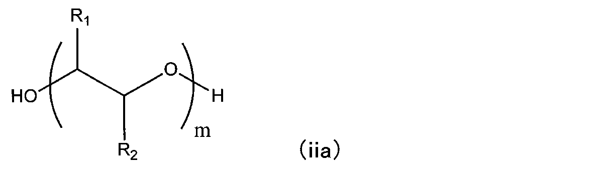
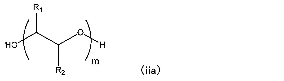
- R 1 and R 2 each represent a hydrogen atom or an alkyl group having 1 to 18 carbon atoms, at least one of which is a hydrogen atom.
- a plurality of R 1 's may be the same or different, and a plurality of R 2 's may be the same or different.
- m represents an integer of 15 or more and 500 or less, preferably 30 or more and 500 or less.
- those having a number average molecular weight of 150 or more, preferably 200 or more can be used.
- a compound represented by the following general formula (iia-1) can be specifically used.
- R 1 is an alkylene (C2-C20 carbon number) glycolate group
- a 1 is a polyalkylene (C2-C20 carbon number) glycol chain
- R 2 is an oxypropylene group.
- a 2 is a polyethylene glycol chain
- R 3 is a hydroxyethylene group
- n is a propylene glycolate group having a valence of 2
- the compound is represented by the following general formula (iia-1).
- R 3 and R 4 each represent a hydrogen atom or an alkyl group having 1 to 18 carbon atoms, at least one of which is a hydrogen atom.
- a+c is an integer of 2 or more and 600 or less, preferably 2 or more and 400 or less
- b is an integer of 1 or more and 300 or less, preferably 1 or more and 100 or less.
- Multiple R 3 and R 4 may be the same or different.
- Non-Patent Document 1 The terminal hydroxyl group of the compound represented by general formula (iia) may react with a polymerizable compound such as an isocyanate compound.
- 0.01 to 50 parts by weight, preferably 0.05 to 20 parts by weight, preferably 0.05 to 20 parts by weight of the polyol compound is added to 100 parts by weight of the polymerizable reactive compound (isocyanate compound and thiol compound). 0.1 parts by weight to 10 parts by weight.
- Photochromic responsiveness can be improved by containing a polyol compound.
- Photochromic compound examples include compounds whose absorption characteristics (absorption spectrum) change with respect to light of a specific wavelength.
- Known photochromic compounds can be used, for example, naphthopyran, chromene, spiropyran, spirooxazine and thiospiropyran, benzopyran, stilbene, azobenzene, thioindigo, bisimidazole, spirodihydroindolizine, quinine, perimidine spiro.
- PC-L-Chain (c1) PC-L-Chain-L'-PC' (c2)
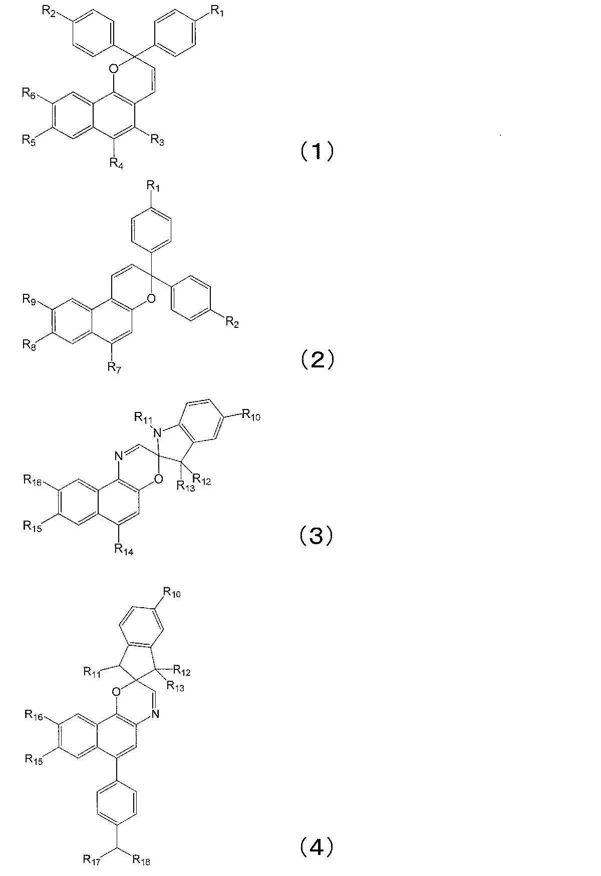
- PC and PC' represent monovalent groups derived from the compounds of general formulas (1) to (4).
- PC and PC' may be the same or different.
- R 1 to R 18 are hydrogen, a halogen atom, a carboxyl group, an acetyl group, a formyl group, an optionally substituted aliphatic group having 1 to 20 carbon atoms, a substituted represents an alicyclic group having 3 to 20 carbon atoms which may be optionally substituted, or an aromatic organic group having 6 to 20 carbon atoms which may be substituted, and may be the same or different.
- These aliphatic groups, alicyclic groups or aromatic organic groups may contain an oxygen atom or a nitrogen atom. Any one group contained in the compounds represented by the general formulas (1) to (4) is bonded to the divalent organic group L or L'.
- the optionally substituted aliphatic group having 1 to 20 carbon atoms includes a linear or branched alkyl group having 1 to 10 carbon atoms, and a linear or branched chain having 1 to 10 carbon atoms.
- Examples of the optionally substituted aromatic organic group having 6 to 20 carbon atoms include a phenyl group, an alkoxyphenyl group having 7 to 16 carbon atoms, an arylamino group, a diarylamino group, and an aryl having 1 to 5 carbon atoms.
- Examples include an alkylamino group, a cyclic amino group, an arylcarbonyl group, and an aroyl group.
- R 1 and R 2 are preferably a hydrogen atom; a halogen atom; Linear or branched C1-C10 alkyl group, linear or branched C1-C10 alkoxy group, C1-C10 hydroxyalkoxy group, C1 C1-C10 alkoxy group substituted with C-10 alkoxy group, C1-C5 haloalkyl group, C1-C5 dihaloalkyl group, C1-C5 trihaloalkyl an optionally substituted aliphatic group having 1 to 20 carbon atoms, such as an alkylamino group having 1 to 5 carbon atoms; phenyl group, C7-C16 alkoxyphenyl group, C1-C5 dialkylamino group, arylamino group, diarylamino group, aryl C1-C5 alkylamino group, cyclic amino group, etc. , an aromatic organic group having 6 to 20 carbon atoms which may be substituted; and the like.
- R 3 is preferably hydrogen atom; halogen atom; carboxyl group; acetyl group; straight or branched C1-C10 alkyl group, straight or branched C2-C10 alkenyl group, straight or branched C1-C1 Alkoxy groups with 10 carbon atoms, hydroxyalkyl groups with 1 to 10 carbon atoms, alkyl groups with 1 to 10 carbon atoms substituted with alkoxy groups with 1 to 10 carbon atoms, and aminoalkyl groups with 1 to 10 carbon atoms.
- an optionally substituted aliphatic group having 1 to 20 carbon atoms such as a linear or branched alkoxycarbonyl group having 1 to 20 carbon atoms; optionally substituted alicyclic groups having 3 to 20 carbon atoms, such as cycloalkyl groups having 3 to 20 carbon atoms and bicycloalkyl groups having 6 to 20 carbon atoms; optionally substituted aromatic organic groups having 6 to 20 carbon atoms, such as an arylcarbonyl group, a formyl group and an aroyl group; R 4 is preferably hydrogen atom; halogen atom; carboxyl group; acetyl group; formyl group; straight or branched C1-C10 alkyl group, straight or branched C2-C10 alkenyl group, straight or branched C1-C1 Alkoxy groups with 10 carbon atoms, hydroxyalkyl groups with 1 to 10 carbon atoms, alkyl groups with 1 to 10 carbon atoms substituted with alkoxy groups
- an optionally substituted aliphatic group having 1 to 20 carbon atoms such as a linear or branched alkoxycarbonyl group having 1 to 20 carbon atoms; optionally substituted alicyclic groups having 3 to 20 carbon atoms, such as cycloalkyl groups having 3 to 20 carbon atoms and bicycloalkyl groups having 6 to 20 carbon atoms; arylcarbonyl group, aroyl group, phenyl group, 7 to 16 carbon atoms alkoxyphenyl group, 1 to 10 carbon atoms dialkoxyphenyl group, 1 to 10 carbon atoms alkylphenyl group, 1 to 10 carbon atoms optionally substituted aromatic organic groups having 6 to 20 carbon atoms, such as 10-dialkylphenyl groups;
- R3 and R4 may be bonded to each other.
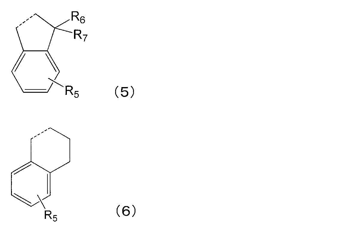
- general formula (5) or (6) may be mentioned.
- the dotted portion represents the bond between the carbon atom to which R3 is attached and the carbon atom to which R4 is attached.
- R 5 , R 6 , R 7 , R 8 , R 9 , R 10 , R 14 , R 15 and R 16 represent the same functional groups as R 1 and R 2 .
- a plurality of R 5 to R 7 may be the same or different.
- R 11 is preferably hydrogen atom; halogen atom; Linear or branched alkyl group with 1 to 20 carbon atoms, haloalkyl group with 1 to 5 carbon atoms, dihaloalkyl group with 1 to 5 carbon atoms, trihaloalkyl group with 1 to 5 carbon atoms, etc.
- an optionally substituted aliphatic group having 1 to 20 carbon atoms a cycloalkyl group having 3 to 20 carbon atoms, a bicycloalkyl group having 6 to 20 carbon atoms, a cycloalkyl group having 3 to 20 carbon atoms substituted with an alkyl group having 1 to 5 carbon atoms, and a cycloalkyl group having 3 to 20 carbon atoms; an optionally substituted alicyclic group having 3 to 20 carbon atoms, such as a bicycloalkyl group having 6 to 20 carbon atoms substituted with an alkyl group having 1 to 5 carbon atoms; optionally substituted aromatic organic groups having 6 to 20 carbon atoms, such as aryl groups substituted with alkyl groups having 1 to 5 carbon atoms;
- R 12 and R 13 are preferably hydrogen atoms; halogen atoms; An optionally substituted aliphatic group having 1 to 20 carbon atoms such as an alkyl group having 1 to 10 carbon atoms and an alkylalkoxycarbonyl group having 1 to 5 carbon atoms; a cyclo having 5 to 7 carbon atoms; an optionally substituted alicyclic group having 3 to 20 carbon atoms such as an alkyl group;
- R 17 and R 18 are preferably a hydrogen atom; a halogen atom; Aliphatic groups having 1 to 20 carbon atoms which may be substituted, such as linear or branched alkyl groups having 1 to 10 carbon atoms and hydroxyalkyl groups having 1 to 10 carbon atoms; an optionally substituted alicyclic group having 3 to 20 carbon atoms, such as a cycloalkyl group having 5 to 7 carbon atoms;
- L and L' of the general formula (c1) or (c2) are divalent organic compounds containing at least one group selected from an oxyethylene chain, an oxypropylene chain, a (thio)ester group, and a (thio)amide group. indicates a group.
- L and L' are represented by general formulas (7) to (13). L and L' may be the same or different.
- Y represents oxygen or sulfur.
- R 19 represents hydrogen or a linear or branched alkyl group having 1 to 10 carbon atoms.
- R 20 represents a linear or branched alkyl group having 1 to 10 carbon atoms.
- p represents an integer of 0-15, and r represents an integer of 0-10.
- Q is a linear or branched C1-C10 alkylene group, C1-C10 alkenylene group, 1,2-, 1,3-, and 1,4-substituted aryl group; and a divalent group derived from a substituted heteroaryl group.
- *1 and *2 represent a bond, *1 is bonded to a monovalent or divalent organic group represented by "Chain”, and *2 is a monovalent organic group represented by PC or PC'. Join.
- Chain in general formula (c1) or (c2) represents a monovalent or divalent organic group containing at least one chain selected from polysiloxane chains and polyoxyalkylene chains.
- polysiloxane chains include polydimethylsiloxane chains, polymethylphenylsiloxane chains, polymethylhydrosiloxane chains, and the like.
- Polyoxyalkylene chains include polyoxyethylene chains, polyoxypropylene chains, polyoxyhexamethylene chains and the like.
- Chain represents a monovalent organic group of general formula (14) or (15) when the photochromic compound is of general formula (c1).
- Chain indicates a divalent organic group of general formula (16) or (17) when the photochromic compound is of general formula (c2).
- R 21 represents a linear or branched alkyl group having 1 to 10 carbon atoms.
- R 22 represents a linear or branched alkyl group having 1 to 10 carbon atoms.
- R23 represents hydrogen, methyl group or ethyl group.
- n represents an integer of 4-75 and m represents an integer of 1-50.
- q represents an integer of 1 to 3; *3 and *4 represent bonds, *3 bonds to the divalent organic group represented by L, and *4 bonds to the divalent organic group represented by L'.
- the photochromic compound (C) of the present embodiment is obtained by the methods described in WO2009/146509, WO2010/20770, WO2012/149599, and WO2012/162725.
- Vivimed's Reversacol Humber Blue polydimethylsiloxane chain, naphthopyran-based chromophore (general formula 3)
- Reversacol Calder Blue polydimethylsiloxane chain, naphthopyran-based chromophore (general formula 3)
- Reversacol Trent Blue polydimethylsiloxane chain, naphthopyran-based chromophore (general formula 3)
- Reversacol Pennine Green polydimethylsiloxane chain, naphthopyran-based chromophore (general formula 3)
- Reversacol Heath Green polyoxyalkylene chain , Naphthopyran-based chromophore (general formula 3)
- Reversacol Chilli Red polydimethylsiloxane chain, naphthopyran-based chromophore (general formula 3)
- the polymerizable composition of the present embodiment contains a photochromic compound of 100 ppm to 10,000 ppm, preferably 1,000 ppm to 8,000 ppm, more preferably 2,500 ppm to 6,000 ppm. can.
- the weight ratio of the polyol compound and the photochromic compound is not particularly limited, but the photochromic compound is preferably 0.01 to 100 parts by weight, more preferably 1 to 10 parts by weight, per 100 parts by weight of the polyol compound. .
- the photochromic compound can also be added by premixing the photochromic compound and the polyisocyanate compound.
- the total amount of polyisocyanate compound used in the present embodiment includes the amount of polyisocyanate compound used in the premix.
- the polymerizable composition of the present embodiment can contain an adhesion improver, a polymerization catalyst, an internal release agent, an ultraviolet absorber, etc., in addition to the above components.
- a polymerizable composition can be obtained by mixing the above components by a predetermined method.
- Step b The polymerizable composition filled in the spaces 22 and the gaps 20 in step a is heated to polymerize and harden, forming a resin layer on the resin substrate 14 to obtain a laminate.
- the polymerization conditions are not limited because the conditions vary depending on the type and amount of the components used, the type and amount of the catalyst used, the shape of the mold, etc., but the temperature is about ⁇ 50 to 150° C. for 1 to 50 hours. It is done over
- Step c After the step b, the laminate composed of the resin layer (photochromic-containing layer) and the resin substrate 14 is released from the substrate 12 and the fixing member 16, and the laminate is taken out.
- Step d Since the obtained laminate has a thick portion cured in the space 22 at the peripheral edge, the polymerizable composition polymerized and cured in the space 22 at the peripheral edge of the laminate is removed, and the gap 22 is removed.
- a step of exposing the photochromic layer obtained by polymerizing and curing inside the laminate on the end face of the laminate may also be included.
- a method for removing a portion of the cured polymerizable composition is not particularly limited.
- a patternless edger Le 1000 Express device manufactured by NIDEK may be used to polish with a high-speed rotating blade to scrape off the polymerizable composition on the periphery until the photochromic layer is exposed on the polished surface.
- the laminated body has a thick portion hardened in the space 22 in the peripheral portion thereof, the thick portion can be appropriately scraped off depending on the application. After that, annealing or the like is performed, and a photochromic lens can be obtained.
- the photochromic lens 30 shown in FIG. 7 is prepared.
- the photochromic lens 30 includes a photochromic layer 32 having an object surface 32a and a resin layer 36 (resin substrate 14).
- the photochromic layer 32 has a protruding portion 34 on its peripheral portion, and the protruding portion 34 is integrated with the resin layer 36 so as to be embedded therein.
- the thickness of the substantially circle center portion of the photochromic layer 32 of the present embodiment is 0.1 to 2.5 mm, preferably 0.3 mm to 2.0 mm, more preferably 0.5 mm to 1.5 mm, and particularly preferably 0.6 mm to 1.2 mm.
- the lower limit of the thickness of the substantially circular center portion of the photochromic layer 32 is 0.1 mm or more, preferably 0.3 mm or more, more preferably 0.5 mm or more, and particularly preferably 0.6 mm or more. is.
- the upper limit of the thickness of the substantially circular center portion of the photochromic layer 32 is 2.5 mm or less, preferably 2.0 mm or less, more preferably 1.5 mm or less, and particularly preferably 1.2 mm or less. is.
- the thickness of the protruding portion 34 on the peripheral edge of the photochromic layer 32 is thicker than the thickness of the portion of the photochromic layer 32 surrounded by the protruding portion 34 .
- the photochromic lens 30 of this embodiment can be used by polishing along the dotted line portion shown in FIG. That is, the photochromic layer 32 is exposed on the end surface of the photochromic lens 30 .
- the four-point average thickness of the peripheral portion of the photochromic layer 32 is preferably 0.1 to 2.5 mm, more preferably 0.3 mm to 2.0 mm, and more preferably 0.5 mm to 1.5 mm. more preferably 0.6 mm to 1.2 mm.
- the lower limit of the thickness of the substantially circular center portion of the photochromic layer 32 is preferably 0.1 mm or more, more preferably 0.3 mm or more, still more preferably 0.5 mm or more, and particularly preferably 0. .6 mm or more.
- the difference between the four-point average thickness of the peripheral portion of the photochromic layer 32 and the thickness of the substantially circular center portion of the photochromic layer is preferably 0.3 mm or less, more preferably 0.25 mm or less. , 0.2 mm or less.
- the thickness (20° C.) of the photochromic layer 32 can be measured with a dial thickness gauge SM-130LW manufactured by TECLOCK.
- the photochromic lens 30 of the present embodiment suppresses initial coloring, and the initial luminous transmittance measured under the following light control performance evaluation conditions when light is not irradiated and the photochromic compound is not colored: (%) is 80% to 100%, preferably 85% to 100%.
- (Dimming performance evaluation) Using a xenon lamp (180 W) light source device, the molded product sample was colored for 15 minutes under conditions of a temperature of 23° C. and an ultraviolet intensity of 50,000 lux (lx) measured with an integrated photometer, and the color density was confirmed.
- ⁇ Light source USHIO ELECTRIC CO., LTD.
- MS-35AAF/FB ⁇ Instantaneous multi-photometry system: Otsuka Electronics Co., Ltd. MSPD-7700
- FIG. 7 an example in which the photochromic layer 32 and the resin layer 36 are curved has been described.
- a circular flat plate may be used.
- the protruding portion 34 is provided over the entire periphery of the photochromic layer 32 has been described, but it may be provided over approximately half the periphery of the photochromic layer 32, or approximately half the periphery. (1/2) to any selected position less than the entire circumference.
- Luminous transmittance (%) 85% or more B: Luminous transmittance (%) 80% or more and less than 85%
- C Luminous transmittance (%) 70% or more and less than 80%
- Luminous transmittance (%) 9% or more and less than 13% B: Luminous transmittance (%) 13% or more and less than 17%
- the thicknesses of the photochromic layer and the resin substrate were measured at the point where the distance between the front surface and the back surface of the molded body sample was the shortest, and the thickness (mm) of the approximately center portion was obtained. Note that the point where the distance between the front surface and the back surface of the molded body sample was the shortest was the substantially central portion of the molded body sample.
- the thickness of the photochromic layer was measured at four equally spaced points on concentric circles 21 mm apart from the approximate center of the molded body sample, and the average value was defined as the average thickness (mm) at the edge.
- the value obtained by subtracting the thinnest thickness (mm) from the thickest thickness (mm) was taken as the five-point thickness variation (mm).
- a dial thickness gauge SM-130LW manufactured by TECLOCK was used to measure the thickness.
- Photochromic compound D1 a mixture of the following compounds Reversacol Wembley Gray: 200 ppm Reversacol Jalapeno Red: 200ppm Reversacol Marine Blue: 200ppm Reversacol Adriatic Blue: 500ppm Reversacol Mendip Green: 800ppm
- Photochromic compound D2 a mixture of the following compounds Reversacol Wembley Gray: 360 ppm Reversacol Heath Green: 600ppm Reversacol Peacock Blue: 300ppm Reversacol Jalapeno Red: 24ppm
- Photochromic compound D3 a mixture of the following compounds Reversacol Wembley Gray: 180 ppm Reversacol Cayenne Red: 300ppm Reversacol Jalapeno Red: 160ppm Reversacol Mendip Green: 800ppm
- a mixed solution was prepared by charging 00005 parts by weight. This mixed solution was stirred at 25° C. for 1 hour to dissolve completely. Then, 25.5 parts by weight of a thiol composition containing 4-mercaptomethyl-1,8-dimercapto-3,6-dithiaoctane and a thiol composition containing pentaerythritol tetrakis(3-mercaptopropionate) were added to this preparation. and stirred at 25° C. for 30 minutes to obtain a homogeneous solution (polymerizable composition for optical materials). This polymerizable composition for optical materials was defoamed at 600 Pa for 1 hour and filtered through a 1 ⁇ m PTFE filter to obtain a prepared liquid.
- This lens is processed to a diameter of 75 mm, and of the edge thickness of 11 mm, 7 mm in the thickness direction from the convex surface (surface 14a) and 2 mm in the thickness direction from the edge portion (peripheral end) are shaved, and the entire circumference is cut.
- a resin substrate S1 (resin substrate 14) having a notch 24 was prepared. The thickness of the substantially circular center portion of the resin substrate S1 was 6 mm.
- a glass mold having a concave surface (surface 12a) of R215.80 mm is used as the substrate 12, and a tape (fixing member 16) is attached so that the concave surface (surface 12a) of the substrate 12 and the convex surface (surface 14a) of the resin substrate S1 face each other.
- the end portion of the substrate 12 and the end portion of the resin substrate S1 were wound and fixed, and the injection molding apparatus 10 having the gap 20 was produced.
- the distance between the centers of the gap 20 was 0.5 mm.
- a space 22 was formed along the entire periphery of the gap 20 by being surrounded by the tape (fixing member 16 ), the concave surface (surface 12 a ) of the substrate 12 and the notch 24 .
- An opening (injection part 18 ) communicating with the space 22 was formed in the fixing member 16 .
- Composition 9 previously containing 2,5-bis(isocyanatomethyl)bicyclo-[2.2.1]-heptane and 2,6-bis(isocyanatomethyl)bicyclo-[2.2.1]-heptane 0.02 parts by weight of Reversacol Wembley Gray manufactured by Vivimed, 0.02 parts by weight of Reversacol Jalapeno Red manufactured by Vivimed, 0.02 parts by weight of Reversacol Marine Blue manufactured by Vivimed, and 0.02 parts by weight of Reversacol Marine Blue manufactured by Vivimed.
- a master solution was prepared by dissolving 0.05 parts by weight of Reversacol Adriatic Blue manufactured by Vivimed, 0.08 parts by weight of Reversacol Reversacol Mendip Green manufactured by Vivimed, and 0.075 parts by weight of HOSTAVIN PR-25 as an ultraviolet absorber. .
- Composition 30.28 containing 2,5-bis(isocyanatomethyl)bicyclo-[2.2.1]-heptane and 2,6-bis(isocyanatomethyl)bicyclo-[2.2.1]-heptane 10 parts by weight of the obtained master solution was added to parts by weight and stirred, and then 2.52 parts by weight of Adeka Pluronic L-64 manufactured by Adeka Corporation, 0.4 parts by weight of Polyflow KL-100 manufactured by Kyoeisha Chemical Co., Ltd., and acidic 0.05 parts by weight of JP-506H manufactured by Johoku Chemical Industry Co., Ltd. was added as a phosphate ester, and the mixture was stirred at 15° C. to 20° C. for 30 minutes (mixing step A).
- This solution was added to the liquid mixture obtained in the mixing step B and stirred at 15° C. to 20° C. for 15 minutes to obtain a polymerizable composition (mixing step C).
- the viscosity of this polymerizable composition (Brookfield viscometer, 25° C., 60 rpm, rotor number 2) was 48.5 mPa ⁇ s.
- the polymerizable composition is stirred and degassed for 1 hour and 30 minutes at 15° C. to 20° C. under a reduced pressure environment of 400 Pa or less, and then filtered using a 1.0 ⁇ m PTFE filter.
- the obtained polymerizable composition is pipetted into the gap 20 between the glass mold which is the substrate 12 and the resin substrate S1 (resin substrate 14) from the opening (injection part 18) located at the upper end of the injection molding apparatus 10.
- the formulation was injected at an injection rate of 30 ml/min by an injection device equipped with a tip. After casting, the temperature was raised from 10° C. to 130° C. over 24 hours. After cooling to room temperature, the lens was removed from the glass mold (substrate 12) to obtain a lens (thickness at substantially circle center: 6.7 mm) in which the photochromic layer was laminated on the resin substrate S1.
- a photochromic lens was obtained by scraping the resin substrate S1 so that the thickness of the obtained lens at the center of the circle was 1.1 mm.
- the obtained photochromic lens (molded sample) was evaluated and measured in (1) above. The results are shown in Table-1. Moreover, the obtained photochromic lens was colorless and transparent, and had good dimming performance such that it immediately developed color when placed under sunlight and faded when the light was cut off. In addition, fine aggregates and striae were not observed, and the appearance was good.
- Example 2 2,5-bis(isocyanatomethyl)bicyclo-[2.2.1]-heptane and 2,6-bis(isocyanatomethyl)bicyclo-[2.2.1]-
- Example 1 After stirring for 30 minutes, a mixed solution was prepared. This prepared liquid was defoamed at 600 Pa for 1 hour and filtered through a 1 ⁇ m PTFE filter to obtain a prepared liquid. The obtained prepared liquid was polymerized and cured by the same operation as in Example 1 to obtain a resin substrate S4 (resin substrate 14). Using the obtained resin substrate S4, the same operation as in Example 1-1 A photochromic lens was obtained in which the photochromic layer was laminated on the resin substrate S4. The obtained photochromic lens (molded sample) was evaluated and measured in (1) above. The results were as shown in Tables-1 to 4.
- Examples 5 to 25, Comparative Examples 1 to 5 A laminated lens (a photochromic lens in which photochromic layers are laminated) was produced in the same manner as in Example 1, except that the resin base material (resin substrate), components, addition amount, and thickness were changed as shown in Table-1. The obtained photochromic lens (molded sample) was evaluated and measured in (1) above. Evaluation results are shown in Tables 1 to 4.
- REFERENCE SIGNS LIST 10 injection molding device 12 substrate 12a surface (curved surface) 14, 15 resin substrate 14a, 15a surface (curved surface) REFERENCE SIGNS LIST 16 fixing member 18 injection part 20 gap 22 space 23 space 24 notch 30 laminated lens (laminate) 32 Photochromic layer 32a Surface (objective surface) 34 Protruding portion 36 Resin substrate 36a Surface (facing surface) i Width of the space 22 in the thickness direction ii Width of the space 22 in the diameter direction iii Diameter of the resin substrate 36 a, b Curvature radius c, d Width of the resin substrate in the thickness direction
Landscapes
- Engineering & Computer Science (AREA)
- Physics & Mathematics (AREA)
- Manufacturing & Machinery (AREA)
- Mechanical Engineering (AREA)
- Health & Medical Sciences (AREA)
- Ophthalmology & Optometry (AREA)
- General Physics & Mathematics (AREA)
- Optics & Photonics (AREA)
- Spectroscopy & Molecular Physics (AREA)
- General Health & Medical Sciences (AREA)
- Eyeglasses (AREA)
- Casting Or Compression Moulding Of Plastics Or The Like (AREA)
- Optical Filters (AREA)
Abstract
Description
また、特許文献3には、所定の金型を用いた成形体の製造方法が開示されている。
特許文献1に記載のインマス方式で得られたフォトクロミックレンズにおいては、対物面側に必要とされるフォトクロミック化合物の濃度を基準とした組成物が用いられることから、レンズ全体のフォトクロミック化合物の総量が多くなり、初期の着色が認められる場合があった。
特許文献3には、フォトクロミックレンズの製造方法については具体的に開示されておらず、フォトクロミック化合物を用いた場合の課題について示唆されていない。
すなわち、本発明は、以下に示すことができる。
略円形状の基板と、
前記基板の面と対向するように配置された略円形状の樹脂基板と、
前記基板の周端部および前記樹脂基板の周端部を固定する固定部材と、
前記基板と前記樹脂基板との間に形成された、略円中心部の厚さ方向の幅が0.1~2.5mmの間隙と、
前記固定部材に設けられた、前記間隙内に重合性組成物を注入するための注入部と、
前記間隙の周縁の少なくとも一部に形成された、前記注入部と前記間隙とを連通する空間と、を備え、
前記空間は前記樹脂基板の周縁の少なくとも一部に形成され、当該空間の厚さ方向の幅は当該間隙の厚さ方向の幅よりも大きい、注入成形装置を用いた、フォトクロミックレンズの製造方法であって、
前記注入部から、前記重合性組成物を注入し、前記空間を介して前記間隙に当該重合性組成物を充填する工程と、
充填された前記重合性組成物を加熱して重合硬化させ、前記樹脂基板上にフォトクロミック層を形成する工程と、
得られた前記樹脂基板と前記フォトクロミック層とからなる積層体を取り出す工程と、
を含み、
前記重合性組成物は、イソシアネート化合物と、チオール化合物と、ポリオール化合物と、フォトクロミック化合物と、を含有する、フォトクロミックレンズの製造方法。
[2]
前記重合組成物は、前記フォトクロミック化合物を100~10,000ppm含有する、[1]に記載のフォトクロミックレンズの製造方法。
[3]
前記フォトクロミック化合物がナフトピラン系化合物である、[1]または[2]に記載のフォトクロミックレンズの製造方法。
[4]
前記ポリオール化合物が下記一般式(iia)で表される化合物である、[1]~[3]のいずれか一項に記載のフォトクロミックレンズの製造方法。
[5]
前記樹脂基板がチオウレタン樹脂を含む、[1]~[4]いずれか一項に記載のフォトクロミックレンズの製造方法。
[6]
前記重合性組成物の粘度(25℃)が5~1000mPa・sである、[1]~[5]いずれか一項に記載のフォトクロミックレンズの製造方法。
[7]
前記積層体を取り出す前記工程のあと、さらに
前記積層体の周縁の前記空間内で重合硬化した前記重合性組成物を除去し、前記間隙内で重合硬化して得られた前記フォトクロミック層を当該積層体の端面に露出させる工程を含む、[1]~[6]いずれか一項に記載のフォトクロミックレンズの製造方法。
[8]
対物面を備えるフォトクロミック層と、前記フォトクロミック層上に積層された樹脂基板と、を備え、
前記フォトクロミック層の略円中心部の厚みが0.1~2.5mmであり、
前記フォトクロミック層にフォトクロミック化合物を含有する、フォトクロミックレンズ。
[9]
前記フォトクロミック層の周縁部の4点平均厚みが0.1~2.5mmである、[8]に記載のフォトクロミックレンズ。
[10]
前記フォトクロミック層の周縁部の4点平均厚みと、前記フォトクロミック層の略円中心部の厚みとの差が、0.3mm以下である、[8]または[9]に記載のフォトクロミックレンズ。
[11]
前記フォトクロミック層の周縁の少なくとも一部の厚みが、当該周縁に囲まれた部分の厚みより厚い、[8]または[9]に記載のフォトクロミックレンズ。
[12]
前記フォトクロミック層は、前記フォトクロミック化合物を100~10,000ppm含有する、[8]~[11]いずれか一項に記載のフォトクロミックレンズ。
[13]
前記フォトクロミックレンズの初期視感透過率が80%以上である、[8]~[12]いずれか一項に記載のフォトクロミックレンズ。
[14]
前記対物面を備える前記フォトクロミック層と、前記樹脂基板と、が接している[8]~[13]いずれか一項に記載のフォトクロミックレンズ。
[15]
前記フォトクロミック化合物が、ナフトピラン系化合物である、[8]~[14]いずれか一項に記載のフォトクロミックレンズ。
[16]
前記フォトクロミック層は、イソシアネート化合物と、チオール化合物と、ポリオール化合物と、をさらに含有する、[8]~[15]のいずれか一項に記載のフォトクロミックレンズ。
[17]
前記ポリオール化合物が下記一般式(iia)で表される化合物である、[16]に記載のフォトクロミックレンズ。
[18]
前記樹脂基板がポリチオウレタン樹脂を含む、[8]~[17]いずれか一項に記載のフォトクロミックレンズ。
本発明のフォトクロミックレンズの製造方法は、
略円形状の基板と、前記基板の面と対向するように配置された略円形状の樹脂基板と、前記基板の周端部および前記樹脂基板の周端部を固定する固定部材と、前記基板と前記樹脂基板との間に形成された、略円中心部の厚さ方向の幅が0.1~2.5mmの間隙と、前記固定部材に設けられた、前記間隙内に重合性組成物を注入するための注入部と、前記間隙の周縁の少なくとも一部に形成された、前記注入部と前記間隙とを連通する空間と、を備え、前記空間は前記樹脂基板の周縁の少なくとも一部に形成され、当該空間の厚さ方向の幅は当該間隙の厚さ方向の幅よりも大きい、注入成形装置を用いて行われる。
具体的に、前記注入部から、イソシアネート化合物、チオール化合物と、ポリオール化合物と、フォトクロミック化合物と、を含有した前記重合性組成物を注入し、前記空間を介して前記間隙に当該重合性組成物を充填する工程と、
充填された前記重合性組成物を加熱して重合硬化させ、前記樹脂基板上にフォトクロミック層(フォトクロミック化合物含有層)を形成する工程と、
得られた前記樹脂基板と前記フォトクロミック層とからなる積層体を取り出す工程と、
を含む。
図1の概略断面図に示すように、本実施形態の注入成形装置10は、略円形状の基板12と、基板12の面12aと対向するように配置された略円形状の樹脂基板14と、基板12の周端部および樹脂基板14の周端部を固定する固定部材16と、固定部材16に設けられた、基板12と樹脂基板14との間隙20内に重合性組成物を注入するための注入部18と、を備える。間隙20の周縁全体に亘って空間22を備える。本実施形態において、間隙20内に充填した重合性組成物を重合することによって、成形体を得ることができる。
間隙20の厚さ方向の幅を上記下限値以上とすることにより、間隙20内で重合性組成物が適度に流動し均一に充填されるため、フォトクロミック化合物の偏りを低減できるようになる。一方、間隙20の厚さ方向の幅を上記上限値以下とすることにより、樹脂基板14上に所定の層厚を有するフォトクロミック層を積層することができ、フォトクロミック化合物の濃度を高めても、初期の着色を抑制しやすくなり、フォトクロ応答性に優れたフォトクロミックレンズを得ることができる。
また、従来技術においては、スピンコート法等を用いて重合性組成物を塗工しフォトクロミック層を得ていたため、フォトクロミック層の周縁部でのフォトクロミック化合物濃度が高くなりやすい傾向があった。これに対し、本実施形態では、間隙20内に重合性組成物を均一に充填できるため、フォトクロミック化合物の偏りを低減できる。
樹脂基板14の直径iiiは、50mm~100mm程度である。
樹脂基板14の直径iiiに対する空間22の基板直径方向の幅iiの比(ii/iii)は、0を超え0.27以下であり、好ましくは0.01~0.27程度である。
すなわち、本実施形態の重合性組成物は後述するように比較的粘度が高いものであるため充填時に気泡を巻き込みやすい傾向があるが、本実施形態の注入成形装置10によれば、幅が広い空間22を介して間隙20に重合性組成物が充填されるため、気泡の混入を抑制することができる。
本実施形態において用いられる重合性組成物の粘度は5~1000mPa・s、好ましくは10~500mPa・sとすることができる。
重合性組成物の粘度は、B型粘度計を用いて25℃で測定することができる。
図1においては、基板12の面12aが凹面、樹脂基板14の面14aが凸面となる例によって説明したが、面12aが凸面、面14aが凹面であってもよい。
図6の概略断面図に示すように、本実施形態の注入成形装置10は、略円形状の基板12と、基板12の面12aと対向するように配置された略円形状の樹脂基板15と、基板12の周端部および樹脂基板15の周端部を固定する固定部材16と、固定部材16に設けられた、基板12と樹脂基板15との間隙20内に重合性組成物を注入するための注入部18と、を備える。
基板12の湾曲面12aと、湾曲面12aと対向する樹脂基板15の湾曲面15aとの間に間隙20を備え、樹脂基板15の湾曲面15aの周縁の湾曲面15bの曲率半径bが、周縁に囲まれた湾曲面15aの曲率半径aよりも小さい。これにより、間隙20の周縁に空間23が形成される。
略円形状の基板12および面12a、図示されない注入部18は、第1実施形態と同様であり説明を省略する。
基板12の湾曲面12aと、湾曲面12aと対向する樹脂基板15の湾曲面15aとの間は少なくとも一部が平行であり、間隙20は当該平行な空間に設けられる。
前記フォトクロミック層(フォトクロミック化合物含有層)は後述するようにチオウレタン樹脂からなることから、樹脂基板15はウレタン樹脂またはチオウレタン樹脂からなることが好ましく、チオウレタン樹脂がより好ましい。樹脂基板15に含まれる樹脂を構成するモノマー成分としては、後述する重合性組成物に含まれるモノマー成分を挙げることができ、これらのモノマー成分は同一でも異なっていてもよい。
間隙20の前記幅は当該範囲であることにより、樹脂基板15上に所定の層厚を有するフォトクロミック層を積層することができ、初期の着色が抑制されており、フォトクロ応答性に優れたフォトクロミックレンズを得ることができる。
樹脂基板15の直径iiiは、50mm~100mm程度である。
樹脂基板15の直径iiiに対する、湾曲面15aを備える周縁部分の基板直径方向の幅iiの比(ii/iii)は、0を超え0.27以下であり、好ましくは0.01~0.27程度である。
樹脂基板15を構成するモノマー成分としては、後述する重合性組成物に含まれるモノマー成分を挙げることができ、これらのモノマー成分は同一でも異なっていてもよい。
さらに、樹脂基板15が周縁部分に湾曲面15bを備え、さらに基板12が周縁部分に上記湾曲面を備え、周縁部分において対向する湾曲面により空間23を形成していてもよい。さらに、周縁部分の湾曲面が、円周方向に基板12および樹脂基板14に互い違いに設けられていてもよい。
本実施形態のフォトクロミックレンズの製造方法は、上述の注入成形装置10を用いて実施され、以下の工程を含む。
工程a:注入部18から、イソシアネート化合物と、チオール化合物と、ポリオール化合物と、フォトクロミック化合物と、を含有した前記重合性組成物を注入し、空間22を介して間隙20に当該重合性組成物を充填する。
工程b:充填された前記重合性組成物を加熱して重合硬化させ、樹脂基板14上にフォトクロミック層を形成する。
工程c:得られた前記フォトクロミック層と樹脂基板14とからなる積層体を取り出す。
本実施形態の注入成形装置を用いたフォトクロミックレンズの製造方法によれば、樹脂基板上に所定の層厚を有するフォトクロミック化合物を含有するフォトクロミック層を積層することができ、初期の着色が抑制されており、フォトクロ応答性に優れたフォトクロミックレンズが得られる。さらに、重合性組成物を、基板12と樹脂基板14との間に形成される間隙20に均一に充填することができ、気泡の混入や脈理の発生等が抑制された外観に優れたフォトクロミックレンズを製造することができる。
また、さらに、以下の工程dを含んでもよい。
工程d:上記の積層体の周縁の空間22内で重合硬化した当該重合性組成物を除去し、間隙20内で重合硬化して得られた当該フォトクロミック層を当該積層体の端面に露出させる。
これにより、均一な厚みのフォトクロミック層と樹脂基板14とからなる積層体が得られ、フォトクロミックレンズとして好適に使用できるようになる。
本実施形態の注入成形方法は、まず、本実施形態の注入成形装置10を注入部18が水平面に対して垂直方向の上方に位置するように配置する。なお、偏光レンズを調製するには、樹脂基板14の面14a表面に予め偏光フィルムを接着させておくことができる。
当該重合性組成物の粘度は5mPa・s~1000mPa・s、好ましくは10mPa・s~500mPa・sとすることができる。
イソシアネート化合物としては、脂肪族イソシアネート化合物、脂環族イソシアネート化合物、芳香族イソシアネート化合物、複素環イソシアネート化合物、芳香脂肪族イソシアネート化合物等が挙げられ、1種または2種以上混合して用いられる。これらのイソシアネート化合物は、二量体、三量体、プレポリマーを含んでもよい。
これらのイソシアネート化合物としては、WO2011/055540号に例示された化合物を挙げることができる。
チオール化合物としては、2以上のメルカプト基を有するポリチオール化合物、1以上のメルカプト基と1以上の水酸基を有するヒドロキシチオール化合物等が挙げられ、1種または2種以上混合して用いられる。これらのチオール化合物としては、WO2016/125736号に例示された化合物を挙げることができる。
チオール化合物は、2以上のメルカプト基を有するポリチオール化合物が好ましい。
ポリオール化合物としては、本発明の本発明の効果を奏する範囲で公知の化合物を用いることができ、例えば、WO2018/158813号に記載の重合体(ii)を用いることができる。本実施形態においては、下記一般式(iia)で表される化合物を用いることが好ましい。

一般式(iia)で表される化合物としては、数平均分子量が150以上、好ましくは200以上のものを用いることができる。

なお、一般式(iia)で表される化合物の末端水酸基は、イソシアネート化合物等の重合性化合物と反応する場合もある。
フォトクロミック化合物としては、特定の波長の光に対して吸光特性(吸収スペクトル)が変化する化合物が挙げられる。
フォトクロミック化合物としては、公知のものを使用することができ、例えば、ナフトピラン、クロメン、スピロピラン、スピロオキサジンおよびチオスピロピラン、ベンゾピラン、スチルベン、アゾベンゼン、チオインジゴ、ビスイミダゾール、スピロジヒドロインドリジン、キニーネ、ペリミジンスピロシクロヘキサジエノン、ビオロゲン、フルギド、フルギミド、ジアリールエテン、ヒドラジン、アニリン、アリールジスルフィド、アリールチオスルホネート、スピロペリミジン、トリアリールメタンなどの化合物から誘導される化合物が挙げられる。
本実施形態においては、フォトクロミック化合物としてナフトピラン誘導体を用いることが好ましい。
PC-L-Chain (c1)
PC-L-Chain-L'-PC' (c2)
PCとPC'は一般式(1)~(4)の化合物から誘導される1価の基を示す。PCとPC'は同一でも異なっていてもよい。
置換されてもよい炭素数3~炭素数20の脂環族基として、炭素数3~炭素数20のシクロアルキル基、炭素数6~炭素数20のビシクロアルキル基等を挙げることができる。
直鎖あるいは分枝鎖状の炭素数1~炭素数10アルキル基、直鎖あるいは分枝鎖状の炭素数1~炭素数10アルコキシ基、炭素数1~炭素数10ヒドロキシアルコキシ基、炭素数1~炭素数10アルコキシ基で置換された炭素数1~炭素数10アルコキシ基、炭素数1~炭素数5ハロアルキル基、炭素数1~炭素数5ジハロアルキル基、炭素数1~炭素数5トリハロアルキル基、炭素数1~炭素数5アルキルアミノ基等の、置換されてもよい炭素数1~炭素数20の脂肪族基;
フェニル基、炭素数7~炭素数16アルコキシフェニル基、炭素数1~炭素数5ジアルキルアミノ基、アリールアミノ基、ジアリールアミノ基、アリール炭素数1~炭素数5アルキルアミノ基、環状アミノ基等の、置換されてもよい炭素数6~炭素数20の芳香族有機基;等を挙げることができる。R1とR2は、それぞれ同一でも異なってもよい。
直鎖あるいは分枝鎖状の炭素数1~炭素数10アルキル基、直鎖あるいは分枝鎖状の炭素数2~炭素数10アルケ二ル基、直鎖あるいは分枝鎖状の炭素数1~炭素数10アルコキシ基、炭素数1~炭素数10ヒドロキシアルキル基、炭素数1~炭素数10アルコキシ基で置換された炭素数1~炭素数10アルキル基、炭素数1~炭素数10アミノアルキル基、直鎖あるいは分枝鎖状の炭素数1~炭素数20アルコキシカルボニル基等の、置換されてもよい炭素数1~炭素数20の脂肪族基;
炭素数3~炭素数20のシクロアルキル基、炭素数6~炭素数20のビシクロアルキル基等の、置換されてもよい炭素数3~炭素数20の脂環族基;
アリールカルボニル基、ホルミル基、アロイル基等の、置換されてもよい炭素数6~炭素数20の芳香族有機基;等を挙げることができる。
R4として、好ましくは、水素原子;ハロゲン原子;カルボキシル基;アセチル基;ホルミル基;
直鎖あるいは分枝鎖状の炭素数1~炭素数10アルキル基、直鎖あるいは分枝鎖状の炭素数2~炭素数10アルケ二ル基、直鎖あるいは分枝鎖状の炭素数1~炭素数10アルコキシ基、炭素数1~炭素数10ヒドロキシアルキル基、炭素数1~炭素数10アルコキシ基で置換された炭素数1~炭素数10アルキル基、炭素数1~炭素数10アミノアルキル基、直鎖あるいは分枝鎖状の炭素数1~炭素数20アルコキシカルボニル基等の、置換されてもよい炭素数1~炭素数20の脂肪族基;
炭素数3~炭素数20のシクロアルキル基、炭素数6~炭素数20のビシクロアルキル基等の、置換されてもよい炭素数3~炭素数20の脂環族基;
アリールカルボニル基、アロイル基、フェニル基、炭素数7~炭素数16アルコキシフェニル基、炭素数1~炭素数10ジアルコキシフェニル基、炭素数1~炭素数10アルキルフェニル基、炭素数1~炭素数10ジアルキルフェニル基等の、置換されてもよい炭素数6~炭素数20の芳香族有機基;等を挙げることができる。
直鎖あるいは分枝鎖状の炭素数1~炭素数20アルキル基、炭素数1~炭素数5ハロアルキル基、炭素数1~炭素数5ジハロアルキル基、炭素数1~炭素数5トリハロアルキル基等の、置換されてもよい炭素数1~炭素数20の脂肪族基;
炭素数3~炭素数20のシクロアルキル基、炭素数6~炭素数20のビシクロアルキル基、炭素数1~炭素数5アルキル基で置換された炭素数3~炭素数20シクロアルキル基、炭素数1~炭素数5アルキル基で置換された炭素数6~炭素数20のビシクロアルキル基等の、置換されてもよい炭素数3~炭素数20の脂環族基;
炭素数1~炭素数5アルキル基で置換されたアリール基等の、置換されてもよい炭素数6~炭素数20の芳香族有機基;等を挙げることができる。
炭素数1~炭素数10アルキル基、炭素数1~炭素数5アルキルアルコキシカルボニル基等の、置換されてもよい炭素数1~炭素数20の脂肪族基;炭素数5~炭素数7のシクロアルキル基等の、置換されてもよい炭素数3~炭素数20の脂環族基;等を示す。
直鎖あるいは分枝鎖状の炭素数1~炭素数10アルキル基、炭素数1~炭素数10ヒドロキシアルキル基等の、置換されてもよい炭素数1~炭素数20の脂肪族基;炭素数5~炭素数7のシクロアルキル基等の、置換されてもよい炭素数3~炭素数20の脂環族基;等を示す。
具体的には、LとL'は、一般式(7)~(13)で表される。LとL'は同一でも異なっていてもよい。

Yは、酸素、硫黄を示す。
R19は、水素、直鎖あるいは分枝鎖状の炭素数1~炭素数10アルキル基を示す。
R20は、直鎖あるいは分枝鎖状の炭素数1~炭素数10アルキル基を示す。
pは、0~15の整数を示し、rは、0~10の整数を示す。
*1、*2は結合手を表し、*1は「Chain」で表される1価または2価の有機基と結合し、*2はPCまたはPC' で表される1価の有機基と結合する。
ポリシロキサン鎖としては、ポリジメチルシロキサン鎖、ポリメチルフェニルシロキサン鎖、ポリメチルヒドロシロキサン鎖等が挙げられる。
ポリオキシアルキレン鎖としては、ポリオキシエチレン鎖、ポリオキシプロピレン鎖、ポリオキシヘキサメチレン鎖等が挙げられる。
「Chain」は、フォトクロミック化合物が一般式(c1)の場合は、一般式(14)または(15)の1価の有機基を示す。
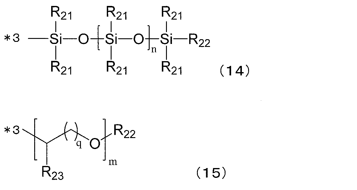
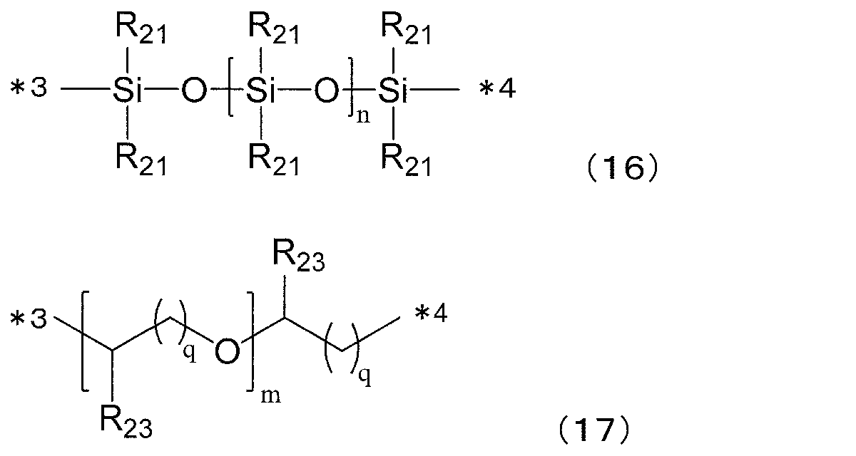
R21は、直鎖あるいは分枝鎖状の炭素数1~炭素数10アルキル基を示す。
R22は、直鎖あるいは分枝鎖状の炭素数1~炭素数10アルキル基を示す。
R23は、水素、メチル基、エチル基を示す。
nは4~75の整数を示し、mは1~50の整数を示す。
qは1~3の整数を示す。
*3、*4は結合手を表し、*3はLで表される2価の有機基と結合し、*4はL'で表される2価の有機基と結合する。
Reversacol Jalapeno Red(ポリオキシアルキレン鎖、ナフトピラン系発色団(一般式3))、
Reversacol Marine Blue(ポリオキシアルキレン鎖、ナフトピラン系発色団(一般式3))、
Reversacol Adriatic Blue(ポリオキシアルキレン鎖、ナフトピラン系発色団(一般式3))、
Reversacol Mendip Green(ポリオキシアルキレン鎖、ナフトピラン系発色団(一般式3))、等が挙げられ、1種または2種以上組み合わせて用いることができる。
ポリオール化合物とフォトクロミック化合物との重量比は特に限定されるものではないが、ポリオール化合物100重量部に対してフォトクロミック化合物が好ましくは0.01~100重量部、より好ましくは1~10重量部である。
フォトクロミック化合物は、当該フォトクロミック化合物とポリイソシアネート化合物とのプレミックスにより添加することもできる。なお、本実施形態におけるポリイソシアネート化合物の使用全量は、プレミックスに用いられるポリイソシアネート化合物の量を含む。
本実施形態の重合性組成物は、上記の成分以外に、密着性向上剤、重合触媒、内部離型剤、紫外線吸収剤などを含むことができる。
重合性組成物は、上記の成分を所定の方法で混合することにより得ることができる。
工程aで空間22および間隙20に充填された前記重合性組成物を加熱して重合硬化させ、樹脂基板14上に樹脂層を形成し、積層体を得る。
重合条件については、成分の種類と使用量、触媒の種類と使用量、モールドの形状等によって条件が異なるため限定されるものではないが、およそ、-50~150℃の温度で1~50時間かけて行われる。
工程bの後、基板12や固定部材16から、前記樹脂層(フォトクロミック含有層)と樹脂基板14とからなる積層体を離型し、当該積層体取り出す。
得られた積層体は、その周縁部に空間22内で硬化した膜厚の厚い部分が存在することから、積層体の周縁の空間22内で重合硬化した重合性組成物を除去し、間隙22内で重合硬化して得られたフォトクロミック層を積層体の端面に露出させる工程を含んでもよい。硬化した重合性組成物の一部を除去する方法は特に限定されない。例えば、NIDEK社製パターンレスエッジャーLe 1000 Express装置を用いて高速回転刃で研磨を施し、研磨面にフォトクロミック層が露出するまで周縁部の重合性組成物を削り取ってもよい。
すなわち、積層体は、その周縁部に空間22内で硬化した膜厚の厚い部分が存在することから、用途に応じて膜厚の厚い部分を適宜削り取ることができる。
その後、アニール等を行い、フォトクロミックレンズを得ることができる。
本実施形態の製造方法において、図7に示されるフォトクロミックレンズ30が調製される。フォトクロミックレンズ30は、対物面32aを備えるフォトクロミック層32と、樹脂層36(樹脂基板14)とを備える。
フォトクロミック層32はその周縁部に突出部34を備え、突出部34は樹脂層36に埋め込まれるように一体化されている。本実施形態のフォトクロミック層32の略円中心部の厚みは、0.1~2.5mmであり、好ましくは0.3mm~2.0mm、さらに好ましくは0.5mm~1.5mm、特に好ましくは0.6mm~1.2mmである。また、フォトクロミック層32の略円中心部の厚みの下限値は、0.1mm以上であり、好ましくは0.3mm以上であり、さらに好ましくは0.5mm以上であり、特に好ましくは0.6mm以上である。一方、フォトクロミック層32の略円中心部の厚みの上限値は、2.5mm以下であり、好ましくは2.0mm以下であり、さらに好ましくは1.5mm以下であり、特に好ましくは1.2mm以下である。
また、本実施形態においては、フォトクロミック層32の周縁の突出部34の厚みは、突出部34に囲まれた部分のフォトクロミック層32の厚みより厚い。
この場合、フォトクロミック層32の周縁部の4点平均厚みが0.1~2.5mmであることが好ましく、0.3mm~2.0mmであることがより好ましく、0.5mm~1.5mmであることがさらに好ましく、0.6mm~1.2mmであることがことさらに好ましい。また、フォトクロミック層32の略円中心部の厚みの下限値は、好ましくは0.1mm以上であり、より好ましくは0.3mm以上であり、さらに好ましくは0.5mm以上であり、特に好ましくは0.6mm以上である。
また、フォトクロミック層32の周縁部の4点平均厚みと、記フォトクロミック層の略円中心部の厚みとの差が、0.3mm以下であることが好ましく、0.25mm以下であることがより好ましく、0.2mm以下であることがさらに好ましい。
本実施形態のフォトクロミックレンズ30は、初期の着色が抑制されており、以下の調光性能評価の条件で測定された、光が照射されずフォトクロミック化合物が発色していない状態の初期視感透過率(%)が80%~100%であり、好ましくは85%~100%である。
(調光性能評価)
キセノンランプ(180W)光源装置を用いて、温度23℃、積算光量計で測定した紫外線強度50000ルクス(lx)の条件で、成形体サンプルを15分間発色させ発色濃度を確認した。
・光源:ウシオ電気(株)MS-35AAF/FB
・瞬間マルチ測光システム:大塚電子(株)MSPD-7700
成形体サンプルの性能試験において、消色時の色調、耐光性は、以下の方法により評価した。
・23℃最大発色濃度:ウシオ電気社製励起光源キセノンランプMS-35AAA/FB2000-Oを備えた、大塚電子製瞬間マルチ測光システムMSPD-7700を用いて、得られた成形体サンプルに、温度23℃、照度50000ルクスの条件で、励起光を15分間照射する。15分後の分光透過率を測定し、ISO8980-3に基づいて、視感透過率を算出した。
[初期着色値(初期視感透過率ともいう)]
A:視感透過率(%)85%以上
B:視感透過率(%)80%以上85%未満
C:視感透過率(%)70%以上80%未満
A:視感透過率(%)9%以上13%未満
B:視感透過率(%)13%以上17%未満
C:視感透過率(%)17%以上21%未満
D:視感透過率(%)21%以上25%未満
E:視感透過率(%)25%以上
成形体サンプルに、温度23℃で、ウシオ電機MS-35AAF/FBキセノンランプ光源装置(照度50000ルクス)を用いて、15分間光線照射した後、光線照射を止めてから成形体サンプルの550nmにおける吸光度が発色前後の吸光度の中間値まで回復するのに要する時間を測定した。この時間を退色速度とし、以下の基準で評価した。発色時の視感透過率が低く、退色速度が速い成形体サンプルを調光性能が良好と判断した。
A:60秒以下
B:60秒を超えた
作成された成形体サンプルを高圧水銀灯(光源型式OPM-252HEG:ウシオ電機社製)で投影し、透過した像について目視にて脈理の有無を観察し、以下の基準で評価した。
〇:全く脈理がなかった。
△:部分的、または数本の脈理があった。肉眼で脈理を確認することができないが水銀灯で確認することができた。
△-×:全体的、1~9本の脈理があった。肉眼で脈理を確認することができないが水銀灯で確認することができた。
×:全体的、または10本以上の脈理があった。肉眼ではっきり脈理を確認することができた。
××:全体的、または15本以上の脈理があった。肉眼ではっきり脈理を確認することができた。
成形体サンプルの表面と裏面の距離が最短となる点におけるフォトクロミック層と樹脂基板の厚みをそれぞれ測定し、略中心部の厚み(mm)とした。なお、成形体サンプルの表面と裏面の距離が最短となる点は、成形体サンプルにおける略中心部であった。
また、成形体サンプルの略中心部から21mm離れた同心円上の等間隔な4点でのフォトクロミック層の厚みを測定し、その平均値を端部の平均厚み(mm)とした。
上記で測定されたフォトクロミック層の略中心部の厚みと端部4点の厚みについて、最も厚い厚み(mm)から最も薄い厚み(mm)を引いた値を5点厚みバラツキ(mm)とした。
なお、厚みの測定にはTECLOCK社製 ダイヤルシックネスゲージ SM-130LWを用いた。
太陽光下に成形サンプルを1分間放置した後、成形サンプルの外観を目視確認し、以下の評価基準に従い評価した。
有り:レンズ略中心部よりレンズ外周部の色の濃度が濃く見えた。
なし:レンズ略中心部とレンズ外周部の色の濃度差が無いように見えた。
実施例においては以下の原料を用いた。
(ポリオール)
・ポリオールA:ポリエチレングリコールポリプロピレングリコールポリエチレングリコール(PluronicL64、BASF社製)
・ポリオールB:ポリオキシエチレンポリオキシプロピレングリコール、(PluronicF127、BASF社製)
・フォトクロミック化合物D1:以下の化合物の混合物
Reversacol Wembley Grey:200ppm
Reversacol Jalapeno Red:200ppm
Reversacol Marine Blue:200ppm
Reversacol Adriatic Blue:500ppm
Reversacol Mendip Green:800ppm
Reversacol Wembley Grey:360ppm
Reversacol Heath Green:600ppm
Reversacol Peacock Blue:300ppm
Reversacol Jalapeno Red:24ppm
Reversacol Wembley Grey:180ppm
Reversacol Cayenne Red:300ppm
Reversacol Jalapeno Red:160ppm
Reversacol Mendip Green:800ppm
[実施例1]
(樹脂基板S1および注入成形装置10の作成)
ジブチル錫ジクロリドを0.035重量部、STEPAN社製ZelecUNを0.1重量部、2,5-ビス(イソシアナトメチル)ビシクロ-[2.2.1]-ヘプタンと2,6-ビス(イソシアナトメチル)ビシクロ-[2.2.1]-ヘプタンとの混合物を50.6重量部、紫外線吸収剤として共同薬品社製Viosob583を1.5重量部、有本化学工業社製PlastBlue8514を0.00005重量部仕込んで混合溶液を作製した。この混合溶液を25℃で1時間攪拌して完全に溶解させた。その後、この調合液に、4-メルカプトメチル-1,8-ジメルカプト-3,6-ジチアオクタンを含むチオール組成物25.5重量部と、ペンタエリスリトールテトラキス(3-メルカプトプロピオネート)を含むチオール組成物23.9重量部とを仕込み、これを25℃で30分攪拌し、均一溶液(光学材料用重合性組成物)を得た。この光学材料用重合性組成物を600Paにて1時間脱泡を行い、1μmPTFEフィルターにて濾過を行い、調合液を得た。
フロントのガラスモールド(バックのガラスモールドに対向する凹面のRが215.80mm)と、バックのガラスモールド(フロントのガラスモールドと対向する凸面のRが75.53mm)とを対向するようにテープで固定された注型モールドを作成した。モールド間の間隙(略円中心部の離間距離6mm)に調合液を注型し、25℃から120℃まで、16時間かけて昇温した。室温まで冷却させて、ガラスモールドから外し、径81mmのレンズを得た。このレンズを、径75mmに加工し、さらにコバ厚11mmのうち凸面(面14a)から厚さ方向に7mmおよびコバ部分(周端部)から直径方向に厚み2mmを削り、全周に亘って切欠き部24を備える樹脂基板S1(樹脂基板14)を作成した。樹脂基板S1の略円中心部の厚みは6mmであった。
基板12として凹面(面12a)がR215.80mmのガラスモールドを使用し、基板12の凹面(面12a)と樹脂基板S1の凸面(面14a)とが対向するように、テープ(固定部材16)で基板12の端部と樹脂基板S1の端部を巻き回して固定し、間隙20を備える注入成形装置10を作成した。間隙20の中心部の離間距離は0.5mmであった。注入成形装置10には、テープ(固定部材16)と基板12の凹面(面12a)と切欠き部24で囲繞されて、間隙20の周縁全体に亘って空間22が形成された。固定部材16に空間22に連通する開口(注入部18)を形成した。
事前に2,5-ビス(イソシアナトメチル)ビシクロ-[2.2.1]-ヘプタンと2,6-ビス(イソシアナトメチル)ビシクロ-[2.2.1]-ヘプタンを含む組成物9.73重量部に、フォトクロミック化合物として、Vivimed社製Reversacol Wembley Greyを0.02重量部、Vivimed社製Reversacol Jalapeno Redを0.02重量部、Vivimed社製 Reversacol Marine Blueを0.02重量部、Vivimed社製 Reversacol Adriatic Blueを0.05重量部、およびVivimed社製 Reversacol Reversacol Mendip Greenを0.08重量部、紫外線吸収剤としてHOSTAVIN PR-25を0.075重量部、溶解してマスター液を準備した。2,5-ビス(イソシアナトメチル)ビシクロ-[2.2.1]-ヘプタンと2,6-ビス(イソシアナトメチル)ビシクロ-[2.2.1]-ヘプタンを含む組成物30.28重量部に、得られたマスター液10重量部を加えて攪拌し、そこにアデカ社製アデカプルロニックL-64を2.52重量部、共栄社化学製ポリフロー KL-100を0.4重量部、酸性リン酸エステルとして城北化学工業社製JP-506Hを0.05重量部、をそれぞれ加えて、15℃~20℃の間で30min攪拌した(混合工程A)。
混合工程Aで得られた混合液に、ペンタエリスリトールテトラキス(3-メルカプトプロピオネート)を19.97重量部、4-メルカプトメチル-1,8-ジメルカプト-3,6-ジチアオクタンを27.23重量部、それぞれ加えて15℃~20℃の間で15min攪拌した(混合工程B)。
事前に2,5-ビス(イソシアナトメチル)ビシクロ-[2.2.1]-ヘプタンと2,6-ビス(イソシアナトメチル)ビシクロ-[2.2.1]-ヘプタンを含む組成物10重量部に、ジメチルチンジクロリドを0.015重量部加え、均一に溶解させて溶液を作成した。この溶液を、混合工程Bで得られた混合液に加えて15℃~20℃の間で15min攪拌し、重合性組成物を得た(混合工程C)。この重合性組成物の粘度(B型粘度計、25℃、60rpm、ローター番号2)は48.5mPa・sであった。
その後、重合性組成物を、400Pa以下の減圧環境下、15℃~20℃の間で1時間30分間、攪拌・脱気を行った後、1.0μmのPTFEフィルターを使用してろ過を行い、得られた重合性組成物を、基板12であるガラスモールドと樹脂基板S1(樹脂基板14)との間の間隙20へ、注入成形装置10の上端に位置する開口(注入部18)からピペットチップを備えた注入器具によって調合液を注入速度30ml/分で注入した。注型した後、10℃から130℃まで、24時間かけて昇温した。室温まで冷却し、ガラスモールド(基板12)から外し、樹脂基板S1上にフォトクロミック層が積層されたレンズ(略円中心部の厚み;6.7mm)を得た。得られたレンズの略円中心部の厚みが1.1mmになるように樹脂基板S1を削りフォトクロミックレンズを得た。
得られたフォトクロミックレンズ(成形体サンプル)について上記(1)の評価・測定を行った。結果を表-1に示す。
また、得られたフォトクロミックレンズは無色透明であり、太陽光線下に置くと直ちに発色し、光線を遮断すると消色するという良好な調光性能を有するものであった。また微細な凝集物および脈理が確認されず、外観が良好なものであった。
樹脂基板を作成する際に、2,5-ビス(イソシアナトメチル)ビシクロ-[2.2.1]-ヘプタンと2,6-ビス(イソシアナトメチル)ビシクロ-[2.2.1]-ヘプタンとの混合物50.6重量部をキシリレンジイソシアネート52.0重量部とし、4-メルカプトメチル-1,8-ジメルカプト-3,6-ジチアオクタンを含むチオール組成物25.5重量部と、ペンタエリスリトールテトラキス(3-メルカプトプロピオネート)を含むチオール組成物23.9重量部を4-メルカプトメチル-1,8-ジメルカプト-3,6-ジチアオクタン組成物48.0重量部とし、樹脂基板14として樹脂基板S2を用いた以外は実施例1と同様の操作で樹脂基板14上にフォトクロミック層が積層されたフォトクロミックレンズを得た。
得られたフォトクロミックレンズ(成形体サンプル)について上記(1)の評価・測定を行った。結果は表-1に示す通りであった。
樹脂基板を作成する際に、
2,5-ビス(イソシアナトメチル)ビシクロ-[2.2.1]-ヘプタンと2,6-ビス(イソシアナトメチル)ビシクロ-[2.2.1]-ヘプタンとの混合物50.6重量部を、キシリレンジイソシアネート50.6重量部とし、
4-メルカプトメチル-1,8-ジメルカプト-3,6-ジチアオクタンを含むチオール組成物25.5重量部と、ペンタエリスリトールテトラキス(3-メルカプトプロピオネート)とを含むチオール組成物23.9重量部を、
5,7-ジメルカプトメチル-1,11-ジメルカプト-3,6,9-トリチアウンデカンと4,7-ジメルカプトメチル-1,11-ジメルカプト-3,6,9-トリチアウンデカンと4,8-ジメルカプトメチル-1,11-ジメルカプト-3,6,9-トリチアウンデカンとの混合物49.4重量部とし、
樹脂基板14として樹脂基板S3を用いた以外は、実施例1と同様の操作で樹脂基板S3上にフォトクロミック層が積層されたフォトクロミックレンズを得た。
得られたフォトクロミックレンズ(成形体サンプル)について上記(1)の評価・測定を行った。結果は表-1に示す通りであった。
(樹脂基板の作成)
ビス(2,3-エピチオプロピル)ジスルフィド 100.0重量部に、N,N-ジメチルシクロヘキシルアミン0.1重量部、N,N-ジシクロヘキシルメチルアミン0.02重量部、BASF社製:TINUVIN PS1.1重量部を溶解させ、さらに、4,8-ジメルカプトメチル-1,11-ジメルカプト-3,6,9-トリチアウンデカン、4,7-ジメルカプトメチル-1,11-ジメルカプト-3,6,9-トリチアウンデカン、および5,7-ジメルカプトメチル-1,11-ジメルカプト-3,6,9-トリチアウンデカンを主成分とする混合物10.0重量部を混合し、20℃で30分間攪拌して調合液を調製した。この調合液を600Paにて1時間脱泡を行い、1μmPTFEフィルターにて濾過を行い、調合液を得た。得られた調合液を、実施例1と同様の操作で重合硬化させ、樹脂基板S4(樹脂基板14)を得た
得られた樹脂基板S4を用いて、実施例1-1と同様の操作で樹脂基板S4上にフォトクロミック層が積層されたフォトクロミックレンズを得た。
得られたフォトクロミックレンズ(成形体サンプル)について上記(1)の評価・測定を行った。結果は表-1~4に示す通りであった。
表-1に記載のように樹脂基材(樹脂基板)、成分および添加量、厚みを変えた以外は実施例1と同様に積層レンズ(フォトクロミック層が積層されたフォトクロミックレンズ)を製造した。
得られたフォトクロミックレンズ(成形体サンプル)について上記(1)の評価・測定を行った。評価結果を表-1~4に示す。
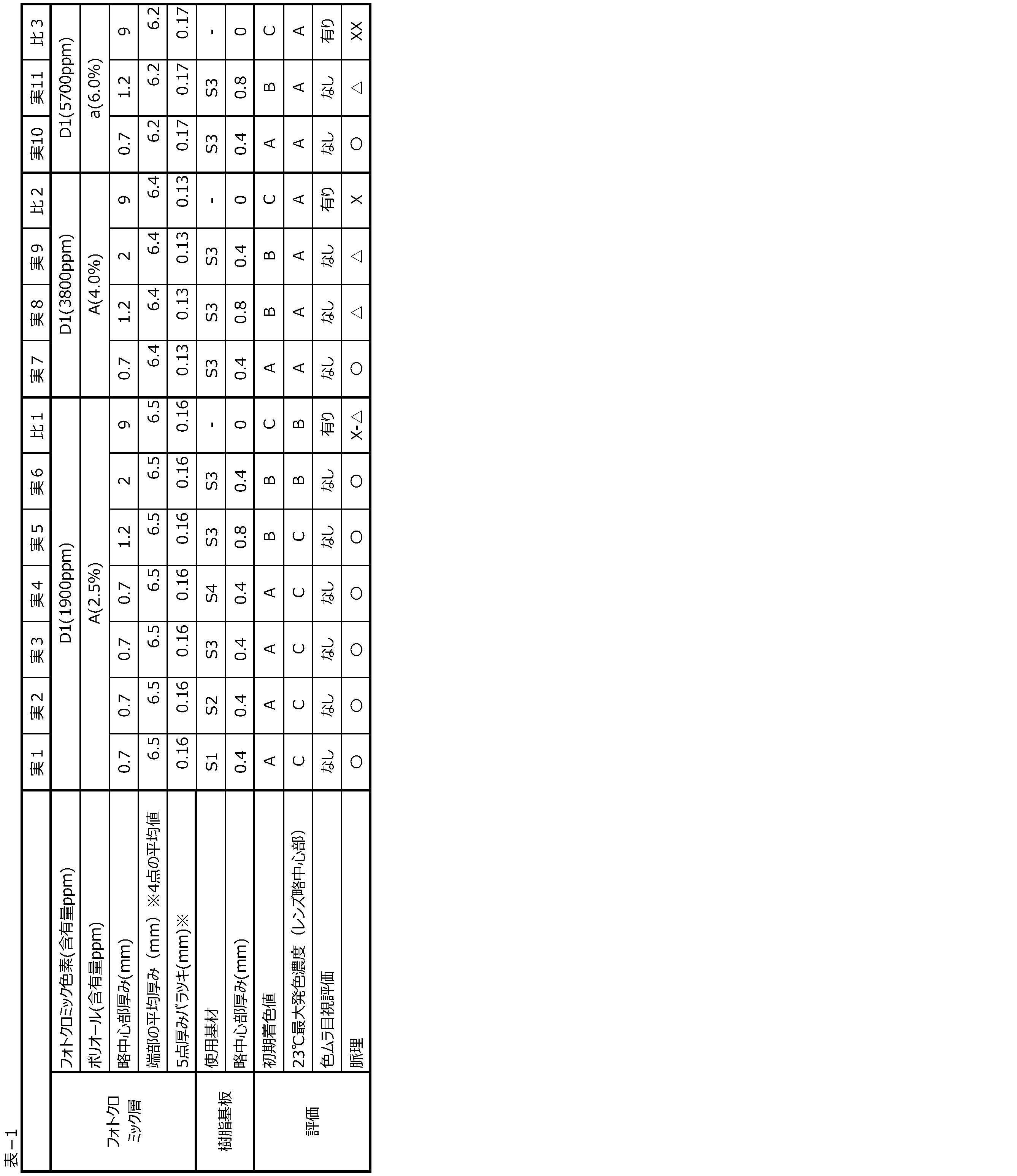


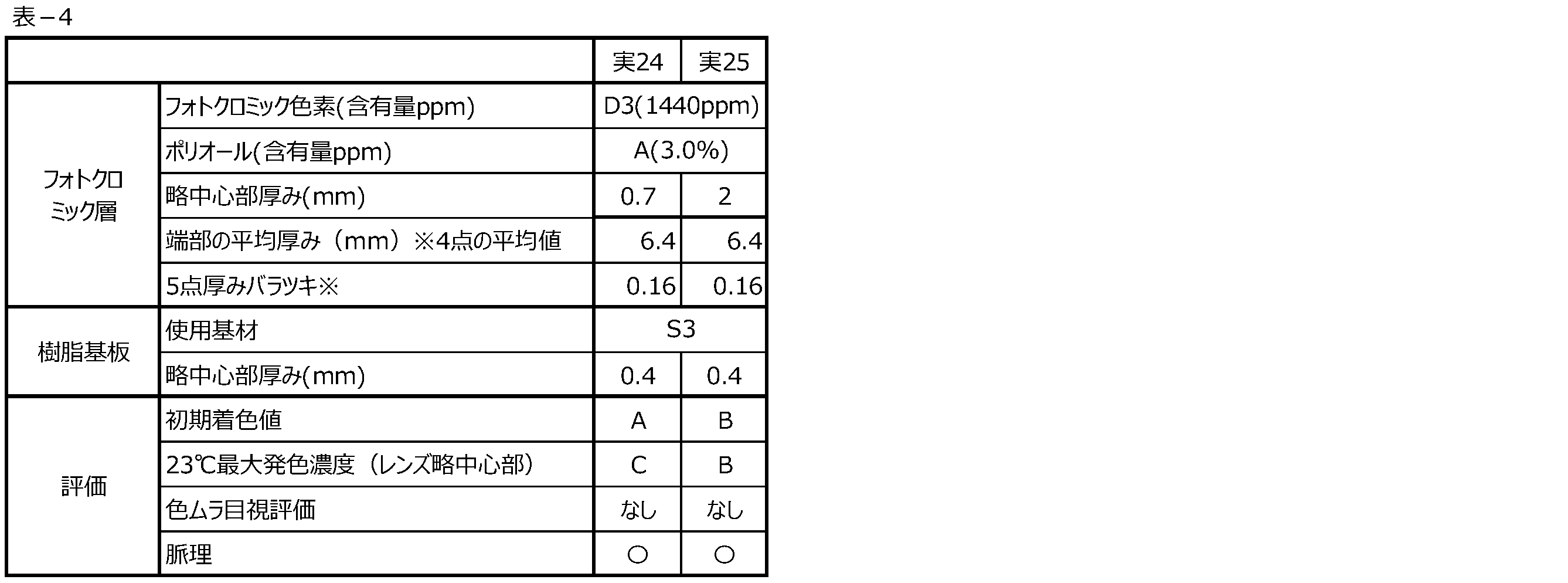
12 基板
12a 面(湾曲面)
14、15 樹脂基板
14a、15a 面(湾曲面)
16 固定部材
18 注入部
20 間隙
22 空間
23 空間
24 切欠き部
30 積層レンズ(積層体)
32 フォトクロミック層
32a 表面(対物面)
34 突出部
36 樹脂基板
36a 表面(対眼面)
i 空間22の厚さ方向の幅
ii 空間22の直径方向の幅
iii 樹脂基板36の直径
a、b 曲率半径
c、d 樹脂基板の厚さ方向の幅
Claims (18)
- 略円形状の基板と、
前記基板の面と対向するように配置された略円形状の樹脂基板と、
前記基板の周端部および前記樹脂基板の周端部を固定する固定部材と、
前記基板と前記樹脂基板との間に形成された、略円中心部の厚さ方向の幅が0.1~2.5mmの間隙と、
前記固定部材に設けられた、前記間隙内に重合性組成物を注入するための注入部と、
前記間隙の周縁の少なくとも一部に形成された、前記注入部と前記間隙とを連通する空間と、を備え、
前記空間は前記樹脂基板の周縁の少なくとも一部に形成され、当該空間の厚さ方向の幅は当該間隙の厚さ方向の幅よりも大きい、注入成形装置を用いた、フォトクロミックレンズの製造方法であって、
前記注入部から、前記重合性組成物を注入し、前記空間を介して前記間隙に当該重合性組成物を充填する工程と、
充填された前記重合性組成物を加熱して重合硬化させ、前記樹脂基板上にフォトクロミック層を形成する工程と、
得られた前記樹脂基板と前記フォトクロミック層とからなる積層体を取り出す工程と、
を含み、
前記重合性組成物は、イソシアネート化合物と、チオール化合物と、ポリオール化合物と、フォトクロミック化合物と、を含有する、フォトクロミックレンズの製造方法。 - 前記重合組成物は、前記フォトクロミック化合物を100~10,000ppm含有する、請求項1に記載のフォトクロミックレンズの製造方法。
- 前記フォトクロミック化合物がナフトピラン系化合物である、請求項1または2に記載のフォトクロミックレンズの製造方法。
- 前記ポリオール化合物が下記一般式(iia)で表される化合物である、請求項1~3のいずれか一項に記載のフォトクロミックレンズの製造方法。

- 前記樹脂基板がチオウレタン樹脂を含む、請求項1~4いずれか一項に記載のフォトクロミックレンズの製造方法。
- 前記重合性組成物の粘度(25℃)が5~1000mPa・sである、請求項1~5いずれか一項に記載のフォトクロミックレンズの製造方法。
- 前記積層体を取り出す前記工程のあと、さらに
前記積層体の周縁の前記空間内で重合硬化した前記重合性組成物を除去し、前記間隙内で重合硬化して得られた前記フォトクロミック層を当該積層体の端面に露出させる工程を含む、請求項1~6いずれか一項に記載のフォトクロミックレンズの製造方法。 - 対物面を備えるフォトクロミック層と、前記フォトクロミック層上に積層された樹脂基板と、を備え、
前記フォトクロミック層の略円中心部の厚みが0.1~2.5mmであり、
前記フォトクロミック層にフォトクロミック化合物を含有する、フォトクロミックレンズ。 - 前記フォトクロミック層の周縁部の4点平均厚みが0.1~2.5mmである、請求項8に記載のフォトクロミックレンズ。
- 前記フォトクロミック層の周縁部の4点平均厚みと、前記フォトクロミック層の略円中心部の厚みとの差が、0.3mm以下である、請求項8または9に記載のフォトクロミックレンズ。
- 前記フォトクロミック層の周縁の少なくとも一部の厚みが、当該周縁に囲まれた部分の厚みより厚い、請求項8~10に記載のフォトクロミックレンズ。
- 前記フォトクロミック層は、前記フォトクロミック化合物を100~10,000ppm含有する、請求項8~11いずれか一項に記載のフォトクロミックレンズ。
- 前記フォトクロミックレンズの初期視感透過率が80%以上である、請求項8~12いずれか一項に記載のフォトクロミックレンズ。
- 前記対物面を備える前記フォトクロミック層と、前記樹脂基板と、が接している請求項8~13いずれか一項に記載のフォトクロミックレンズ。
- 前記フォトクロミック化合物が、ナフトピラン系化合物である、請求項8~14いずれか一項に記載のフォトクロミックレンズ。
- 前記フォトクロミック層は、イソシアネート化合物と、チオール化合物と、ポリオール化合物と、をさらに含有する、請求項8~15のいずれか一項に記載のフォトクロミックレンズ。
- 前記ポリオール化合物が下記一般式(iia)で表される化合物である、請求項16に記載のフォトクロミックレンズ。
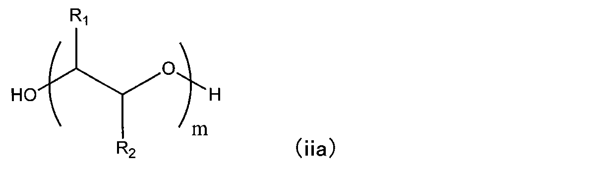
- 前記樹脂基板がポリチオウレタン樹脂を含む、請求項8~17いずれか一項に記載のフォトクロミックレンズ。
Priority Applications (3)
| Application Number | Priority Date | Filing Date | Title |
|---|---|---|---|
| EP22774978.5A EP4318103A4 (en) | 2021-03-22 | 2022-03-03 | Production method for photochromic lens and photochromic lens |
| JP2023508884A JP7777122B2 (ja) | 2021-03-22 | 2022-03-03 | フォトクロミックレンズの製造方法、フォトクロミックレンズ |
| US18/550,795 US20240100789A1 (en) | 2021-03-22 | 2022-03-03 | Method for manufacturing photochromic lens and photochromic lens |
Applications Claiming Priority (2)
| Application Number | Priority Date | Filing Date | Title |
|---|---|---|---|
| JP2021-046914 | 2021-03-22 | ||
| JP2021046914 | 2021-03-22 |
Publications (1)
| Publication Number | Publication Date |
|---|---|
| WO2022202182A1 true WO2022202182A1 (ja) | 2022-09-29 |
Family
ID=83396945
Family Applications (1)
| Application Number | Title | Priority Date | Filing Date |
|---|---|---|---|
| PCT/JP2022/009072 Ceased WO2022202182A1 (ja) | 2021-03-22 | 2022-03-03 | フォトクロミックレンズの製造方法、フォトクロミックレンズ |
Country Status (4)
| Country | Link |
|---|---|
| US (1) | US20240100789A1 (ja) |
| EP (1) | EP4318103A4 (ja) |
| JP (1) | JP7777122B2 (ja) |
| WO (1) | WO2022202182A1 (ja) |
Cited By (3)
| Publication number | Priority date | Publication date | Assignee | Title |
|---|---|---|---|---|
| US20220267509A1 (en) * | 2021-02-25 | 2022-08-25 | Jiangsu Conant Optical Co., Ltd. | Polyurethane-based photochromic resin lens and preparation method thereof |
| WO2024132979A1 (de) * | 2022-12-22 | 2024-06-27 | Rodenstock Gmbh | LINSE, INSBESONDERE OPHTHALMISCHE LINSE, SOWIE VERFAHREN UND VORRICHTUNG ZU DEREN HERSTELLUNG UND GIEßPAKET MIT DER LINSE |
| WO2024204305A1 (ja) * | 2023-03-31 | 2024-10-03 | ホヤ レンズ タイランド リミテッド | イソシアネート組成物、重合性組成物、樹脂、光学材料、及び眼鏡レンズ |
Families Citing this family (1)
| Publication number | Priority date | Publication date | Assignee | Title |
|---|---|---|---|---|
| WO2025195797A1 (en) * | 2024-03-22 | 2025-09-25 | Addoptics B.V. | Method for manufacturing a blank, method for manufacturing an optical system, optical system |
Citations (22)
| Publication number | Priority date | Publication date | Assignee | Title |
|---|---|---|---|---|
| JPS6187757A (ja) | 1984-10-05 | 1986-05-06 | Mitsui Toatsu Chem Inc | 色素およびこれを用いた偏光フイルム |
| JPS61285259A (ja) | 1985-06-13 | 1986-12-16 | Mitsui Toatsu Chem Inc | 二色性色素およびこれを用いた偏光フイルム |
| JPS62270664A (ja) | 1985-06-12 | 1987-11-25 | Mitsui Toatsu Chem Inc | キノフタロン系色素およびこれを用いた偏光フイルム |
| JPH01103667A (ja) | 1987-07-22 | 1989-04-20 | Mitsui Toatsu Chem Inc | アントラキノン系色素および該色素を用いた偏光フィルム |
| JPH08216271A (ja) * | 1995-02-10 | 1996-08-27 | Kureha Chem Ind Co Ltd | 合成樹脂製調光レンズの製造方法 |
| WO2003058300A1 (en) | 2001-12-27 | 2003-07-17 | Transitions Optical, Inc. | Photochromic optical article |
| JP2008030439A (ja) * | 2006-06-30 | 2008-02-14 | Hoya Corp | フォトクロミックレンズの製造方法 |
| WO2009146509A1 (en) | 2008-06-05 | 2009-12-10 | Advanced Polymerik Pty Ltd | Photochromic polymer and composition comprising photochromic polymer |
| WO2010020770A1 (en) | 2008-08-18 | 2010-02-25 | James Robinson Limited | Polydialkylsiloxane-bridged bi-photochromic molecules |
| WO2011055540A1 (ja) | 2009-11-06 | 2011-05-12 | 三井化学株式会社 | 光学材料用内部離型剤の製造方法、光学材料用内部離型剤およびそれを含む重合性組成物 |
| WO2012141306A1 (ja) | 2011-04-13 | 2012-10-18 | Hoya株式会社 | 眼鏡用フォトクロミックレンズ |
| WO2012149599A1 (en) | 2011-05-03 | 2012-11-08 | Advanced Polymerik Pty Ltd | Photochromic polymer |
| WO2012162725A1 (en) | 2011-06-03 | 2012-12-06 | Advanced Polymerik Pty Ltd | Photochromic polymers |
| WO2015005391A1 (ja) * | 2013-07-09 | 2015-01-15 | 株式会社トクヤマ | フォトクロミック硬化性組成物 |
| JP2015069045A (ja) * | 2013-09-30 | 2015-04-13 | タレックス光学工業株式会社 | 複合機能性偏光レンズ |
| US20150231839A1 (en) * | 2014-02-20 | 2015-08-20 | Qspex Technologies, Inc. | Lenses with graded photochromic, molds and methods of making same |
| WO2016125736A1 (ja) | 2015-02-02 | 2016-08-11 | 三井化学株式会社 | 光学材料用重合性組成物、光学材料およびその用途 |
| JP2017040819A (ja) * | 2015-08-20 | 2017-02-23 | 伊藤光学工業株式会社 | 眼鏡素材 |
| WO2018158813A1 (ja) | 2017-02-28 | 2018-09-07 | 三菱電機株式会社 | エレベーターの呼び登録システム |
| JP2020139085A (ja) * | 2019-02-28 | 2020-09-03 | 三井化学株式会社 | 光学材料用重合性組成物 |
| WO2020230889A1 (ja) | 2019-05-16 | 2020-11-19 | 三井化学株式会社 | 注入成形装置、当該装置を用いた注入成形方法および成形体の製造方法、積層レンズ |
| JP2021046914A (ja) | 2019-09-19 | 2021-03-25 | Ntn株式会社 | 円すいころ軸受 |
Family Cites Families (2)
| Publication number | Priority date | Publication date | Assignee | Title |
|---|---|---|---|---|
| EP3919584B1 (en) * | 2019-01-30 | 2025-12-24 | Mitsui Chemicals, Inc. | Method for producing polymerizable composition for optical material |
| CN113825779B (zh) * | 2019-05-16 | 2023-04-28 | 三井化学株式会社 | 光学材料用聚合性组合物及其用途 |
-
2022
- 2022-03-03 EP EP22774978.5A patent/EP4318103A4/en active Pending
- 2022-03-03 US US18/550,795 patent/US20240100789A1/en active Pending
- 2022-03-03 JP JP2023508884A patent/JP7777122B2/ja active Active
- 2022-03-03 WO PCT/JP2022/009072 patent/WO2022202182A1/ja not_active Ceased
Patent Citations (23)
| Publication number | Priority date | Publication date | Assignee | Title |
|---|---|---|---|---|
| JPS6187757A (ja) | 1984-10-05 | 1986-05-06 | Mitsui Toatsu Chem Inc | 色素およびこれを用いた偏光フイルム |
| JPS62270664A (ja) | 1985-06-12 | 1987-11-25 | Mitsui Toatsu Chem Inc | キノフタロン系色素およびこれを用いた偏光フイルム |
| JPS62275163A (ja) | 1985-06-12 | 1987-11-30 | Mitsui Toatsu Chem Inc | アントラキノン系色素およびこれを用いた偏光フイルム |
| JPS61285259A (ja) | 1985-06-13 | 1986-12-16 | Mitsui Toatsu Chem Inc | 二色性色素およびこれを用いた偏光フイルム |
| JPH01103667A (ja) | 1987-07-22 | 1989-04-20 | Mitsui Toatsu Chem Inc | アントラキノン系色素および該色素を用いた偏光フィルム |
| JPH08216271A (ja) * | 1995-02-10 | 1996-08-27 | Kureha Chem Ind Co Ltd | 合成樹脂製調光レンズの製造方法 |
| WO2003058300A1 (en) | 2001-12-27 | 2003-07-17 | Transitions Optical, Inc. | Photochromic optical article |
| JP2008030439A (ja) * | 2006-06-30 | 2008-02-14 | Hoya Corp | フォトクロミックレンズの製造方法 |
| WO2009146509A1 (en) | 2008-06-05 | 2009-12-10 | Advanced Polymerik Pty Ltd | Photochromic polymer and composition comprising photochromic polymer |
| WO2010020770A1 (en) | 2008-08-18 | 2010-02-25 | James Robinson Limited | Polydialkylsiloxane-bridged bi-photochromic molecules |
| WO2011055540A1 (ja) | 2009-11-06 | 2011-05-12 | 三井化学株式会社 | 光学材料用内部離型剤の製造方法、光学材料用内部離型剤およびそれを含む重合性組成物 |
| WO2012141306A1 (ja) | 2011-04-13 | 2012-10-18 | Hoya株式会社 | 眼鏡用フォトクロミックレンズ |
| WO2012149599A1 (en) | 2011-05-03 | 2012-11-08 | Advanced Polymerik Pty Ltd | Photochromic polymer |
| WO2012162725A1 (en) | 2011-06-03 | 2012-12-06 | Advanced Polymerik Pty Ltd | Photochromic polymers |
| WO2015005391A1 (ja) * | 2013-07-09 | 2015-01-15 | 株式会社トクヤマ | フォトクロミック硬化性組成物 |
| JP2015069045A (ja) * | 2013-09-30 | 2015-04-13 | タレックス光学工業株式会社 | 複合機能性偏光レンズ |
| US20150231839A1 (en) * | 2014-02-20 | 2015-08-20 | Qspex Technologies, Inc. | Lenses with graded photochromic, molds and methods of making same |
| WO2016125736A1 (ja) | 2015-02-02 | 2016-08-11 | 三井化学株式会社 | 光学材料用重合性組成物、光学材料およびその用途 |
| JP2017040819A (ja) * | 2015-08-20 | 2017-02-23 | 伊藤光学工業株式会社 | 眼鏡素材 |
| WO2018158813A1 (ja) | 2017-02-28 | 2018-09-07 | 三菱電機株式会社 | エレベーターの呼び登録システム |
| JP2020139085A (ja) * | 2019-02-28 | 2020-09-03 | 三井化学株式会社 | 光学材料用重合性組成物 |
| WO2020230889A1 (ja) | 2019-05-16 | 2020-11-19 | 三井化学株式会社 | 注入成形装置、当該装置を用いた注入成形方法および成形体の製造方法、積層レンズ |
| JP2021046914A (ja) | 2019-09-19 | 2021-03-25 | Ntn株式会社 | 円すいころ軸受 |
Non-Patent Citations (3)
| Title |
|---|
| P. ALEXANDRIDIS, T.A. HATTON/COLLOIDS SURFACES A: PHYSICOCHEM. ENG. ASPECTS, vol. 96, 1995, pages 1 - 46 |
| PHYS. CHEM. CHEM. PHYS., vol. 1, 1999, pages 3331 - 3334 |
| See also references of EP4318103A4 |
Cited By (3)
| Publication number | Priority date | Publication date | Assignee | Title |
|---|---|---|---|---|
| US20220267509A1 (en) * | 2021-02-25 | 2022-08-25 | Jiangsu Conant Optical Co., Ltd. | Polyurethane-based photochromic resin lens and preparation method thereof |
| WO2024132979A1 (de) * | 2022-12-22 | 2024-06-27 | Rodenstock Gmbh | LINSE, INSBESONDERE OPHTHALMISCHE LINSE, SOWIE VERFAHREN UND VORRICHTUNG ZU DEREN HERSTELLUNG UND GIEßPAKET MIT DER LINSE |
| WO2024204305A1 (ja) * | 2023-03-31 | 2024-10-03 | ホヤ レンズ タイランド リミテッド | イソシアネート組成物、重合性組成物、樹脂、光学材料、及び眼鏡レンズ |
Also Published As
| Publication number | Publication date |
|---|---|
| JPWO2022202182A1 (ja) | 2022-09-29 |
| US20240100789A1 (en) | 2024-03-28 |
| JP7777122B2 (ja) | 2025-11-27 |
| EP4318103A1 (en) | 2024-02-07 |
| EP4318103A4 (en) | 2025-03-26 |
Similar Documents
| Publication | Publication Date | Title |
|---|---|---|
| WO2022202182A1 (ja) | フォトクロミックレンズの製造方法、フォトクロミックレンズ | |
| KR102036465B1 (ko) | 광학 재료용 중합성 조성물, 광학 재료, 광학 재료용 중합성 조성물의 제조 방법 및 광학 재료의 제조 방법 | |
| CN104903754B (zh) | 光学材料、光学材料用组合物及其用途 | |
| CN108026241B (zh) | 成型体和光学材料用聚合性组合物 | |
| CN113348223B (zh) | 光学材料用聚合性组合物的制造方法 | |
| TW202100717A (zh) | 光致變色光學物品及其製造方法 | |
| JP2015533874A (ja) | チオウレタン系光学材料の製造方法 | |
| US20250101164A1 (en) | Polythiourethane film, eyeglass lens material, eyeglass lens, and method of producing eyeglass lens | |
| JP7265002B2 (ja) | 注入成形装置、当該装置を用いた注入成形方法および成形体の製造方法、積層レンズ | |
| TW202317708A (zh) | 光硬化性組成物、硬化物、積層體、硬化物的製造方法以及透鏡的製造方法 | |
| JP7299306B2 (ja) | 光学材料の製造方法、光学材料用重合性組成物 | |
| JP2022184063A (ja) | メガネレンズの製造方法及びメガネレンズ | |
| US20230228927A1 (en) | Polymerizable composition for optical material and photochromic lens | |
| KR101831889B1 (ko) | 플라스틱 렌즈용 폴리티올 조성물 | |
| WO2017029825A1 (ja) | 眼鏡素材 | |
| JP2005181426A (ja) | フォトクロミックレンズおよびその製造方法 | |
| JP7837468B2 (ja) | 組成物、組成物キット、硬化物、積層体及び硬化物の製造方法 | |
| KR20200085258A (ko) | 티오에폭시계 광학재료의 제조방법 | |
| WO2026034061A1 (ja) | 光学部材および光学部材の製造方法 | |
| WO2025109980A1 (ja) | 光学部材および光学部材の製造方法 | |
| JP2023011060A (ja) | 光学材料用重合性組成物、当該組成物から得られる成形体およびその用途 | |
| KR20180090721A (ko) | 플라스틱 렌즈용 폴리티올 조성물 |
Legal Events
| Date | Code | Title | Description |
|---|---|---|---|
| 121 | Ep: the epo has been informed by wipo that ep was designated in this application |
Ref document number: 22774978 Country of ref document: EP Kind code of ref document: A1 |
|
| WWE | Wipo information: entry into national phase |
Ref document number: 2023508884 Country of ref document: JP |
|
| WWE | Wipo information: entry into national phase |
Ref document number: 18550795 Country of ref document: US |
|
| WWE | Wipo information: entry into national phase |
Ref document number: 2022774978 Country of ref document: EP |
|
| NENP | Non-entry into the national phase |
Ref country code: DE |
|
| ENP | Entry into the national phase |
Ref document number: 2022774978 Country of ref document: EP Effective date: 20231023 |