WO2022202425A1 - Charging roll for electrophotographic equipment - Google Patents
Charging roll for electrophotographic equipment Download PDFInfo
- Publication number
- WO2022202425A1 WO2022202425A1 PCT/JP2022/011153 JP2022011153W WO2022202425A1 WO 2022202425 A1 WO2022202425 A1 WO 2022202425A1 JP 2022011153 W JP2022011153 W JP 2022011153W WO 2022202425 A1 WO2022202425 A1 WO 2022202425A1
- Authority
- WO
- WIPO (PCT)
- Prior art keywords
- elastic layer
- layer
- less
- surface layer
- charging roll
- Prior art date
- Legal status (The legal status is an assumption and is not a legal conclusion. Google has not performed a legal analysis and makes no representation as to the accuracy of the status listed.)
- Ceased
Links
Images

Classifications
-
- G—PHYSICS
- G03—PHOTOGRAPHY; CINEMATOGRAPHY; ANALOGOUS TECHNIQUES USING WAVES OTHER THAN OPTICAL WAVES; ELECTROGRAPHY; HOLOGRAPHY
- G03G—ELECTROGRAPHY; ELECTROPHOTOGRAPHY; MAGNETOGRAPHY
- G03G15/00—Apparatus for electrographic processes using a charge pattern
- G03G15/02—Apparatus for electrographic processes using a charge pattern for laying down a uniform charge, e.g. for sensitising; Corona discharge devices
- G03G15/0208—Apparatus for electrographic processes using a charge pattern for laying down a uniform charge, e.g. for sensitising; Corona discharge devices by contact, friction or induction, e.g. liquid charging apparatus
- G03G15/0216—Apparatus for electrographic processes using a charge pattern for laying down a uniform charge, e.g. for sensitising; Corona discharge devices by contact, friction or induction, e.g. liquid charging apparatus by bringing a charging member into contact with the member to be charged, e.g. roller, brush chargers
- G03G15/0233—Structure, details of the charging member, e.g. chemical composition, surface properties
Definitions
- the present invention relates to a charging roll for electrophotographic equipment that is suitably used in electrophotographic equipment such as copiers, printers and facsimiles that employ an electrophotographic system.
- Patent Document 1 As a charging roll for electrophotographic equipment, one having an elastic layer having rubber elasticity on the outer peripheral surface of a shaft such as a core metal and a surface layer on the outer peripheral surface of the elastic layer is known. In charging rolls, it is known to use silicone rubber as a material for the elastic layer (Patent Document 1).
- the silicone rubber is soft, the toner in contact with the charging roll is less likely to be crushed, and contamination on the roll surface due to toner crushing is easily suppressed.
- the contact area between the charging roll and the photosensitive member tends to increase.
- silicone rubber is weak against tearing force.
- the elastic layer of the charging roll in contact with the photoreceptor is torn due to the stress during driving, and the charging roll is likely to be broken.
- the charging roll is required to satisfy suppression of toner contamination, suppression of breakage due to tearing of the elastic layer, and satisfactory charging performance.
- peeling of the surface layer from the elastic layer poses a problem.
- the problem to be solved by the present invention is to provide a charging roll for electrophotographic equipment that suppresses toner contamination, tearing and rupture of the elastic layer, and peeling of the surface layer, and has excellent charging properties.
- a charging roll for electrophotographic equipment comprises a shaft, an elastic layer formed on the outer peripheral surface of the shaft, and a surface layer formed on the outer peripheral surface of the elastic layer
- the elastic layer contains silicone rubber, and has a plurality of large projections having a width of 13 ⁇ m or more and 48 ⁇ m or less and a height of 5 ⁇ m or more and 13 ⁇ m or less on the outer peripheral surface of the elastic layer, and the surfaces of the large projections are: It has a plurality of small projections forming unevenness with a ten-point average roughness Rz of 1.0 ⁇ m or more and 6.0 ⁇ m or less, the surface layer contains a urethane polymer, and the breaking elongation of the surface layer is 285% or more and 525%. It is below.
- the NCO index of the urethane polymer is preferably 100 or more and 150 or less.
- the thickness of the surface layer is preferably 0.1 ⁇ m or more and 2.0 ⁇ m or less. It is preferable that the surface layer is formed along an uneven surface formed by a plurality of small projections of the elastic layer. It is preferable that a hydroxy group or a hydroperoxy group is formed on the outer peripheral surface of the elastic layer. It is preferable that a plurality of small projections forming irregularities having a ten-point average roughness Rz of 1.0 ⁇ m or more and 6.0 ⁇ m or less be provided on the surface between the large projections. It is preferable that the distance between the large protrusions is 25 ⁇ m or more and 55 ⁇ m or less.
- the distance between the small protrusions is 0.4 ⁇ m or more and 3.8 ⁇ m or less.
- the surface area ratio S/So of the elastic layer is preferably 2.2 or more and 7.7 or less.
- the number of functional groups of the polyol constituting the urethane polymer is preferably two.
- the outer peripheral surface of the elastic layer is preferably subjected to excimer treatment or corona treatment.
- a shaft, an elastic layer formed on the outer peripheral surface of the shaft, and a surface layer formed on the outer peripheral surface of the elastic layer are provided.
- the elastic layer contains silicone rubber, and a plurality of large protrusions having a width of 13 ⁇ m or more and 48 ⁇ m or less and a height of 5 ⁇ m or more and 13 ⁇ m or less are provided on the outer peripheral surface of the elastic layer, and the surfaces of the large protrusions.
- the surface layer contains a urethane polymer, and the breaking elongation of the surface layer is 285% or more. Since it is 525% or less, it is possible to suppress toner contamination, tear breakage of the elastic layer, and peeling of the surface layer, and to achieve excellent charging properties.
- the NCO index of the urethane polymer is 100 or more and 150 or less
- the elongation at break of the surface layer tends to fall within a specific range.
- the elastic layer easily follows the surface layer, and the surface layer easily follows the elastic layer. By doing so, it is easy to suppress tearing and breaking of the elastic layer, and it is easy to suppress peeling of the surface layer.
- the thickness of the surface layer is 0.1 ⁇ m or more and 2.0 ⁇ m or less, the chargeability and surface roughness are easily maintained.
- the surface layer is formed along the uneven surface formed by the plurality of small projections of the elastic layer, the chargeability and surface roughness are easily maintained.
- the affinity between the elastic layer and the urethane polymer is improved, and the uneven surface formed by a plurality of small protrusions of the elastic layer
- the surface layer is easily formed along the elastic layer, and the surface layer can be covered without filling the surface unevenness of the elastic layer.
- the integration of the elastic layer and the surface layer is enhanced, and peeling of the surface layer is easily suppressed.
- the surface between the large protrusions and the large protrusions has a plurality of small protrusions forming unevenness with a ten-point average roughness Rz of 1.0 ⁇ m or more and 6.0 ⁇ m or less, discharge characteristics can be improved. can.
- the integration of the elastic layer and the surface layer is enhanced, and peeling of the surface layer is easily suppressed.
- the distance between the large protrusions is 25 ⁇ m or more and 55 ⁇ m or less, moderate surface irregularities (roughness) are formed by the plurality of large protrusions, so that the elastic layer and the surface layer are integrated. is increased, and peeling of the surface layer is easily suppressed. Also, excellent discharge characteristics can be maintained. By doing so, it is easy to suppress the occurrence of a fog image.
- the plurality of small protrusions are appropriately dispersed on the surface of the large protrusions, so the stress applied to the small protrusions is is moderately dispersed, and tearing and breaking of small protrusions is easily suppressed.
- the surface layer is easily formed along the uneven surface formed by the plurality of small projections of the elastic layer, so that the surface layer can be covered without filling the unevenness.
- the integration of the elastic layer and the surface layer is enhanced, and peeling of the surface layer is easily suppressed.
- the elastic layer When the surface area ratio S/So of the elastic layer is 2.2 or more and 7.7 or less, the elastic layer has an appropriate surface unevenness (roughness) due to a plurality of large protrusions and a plurality of small protrusions.
- the integration of the layer and the surface layer is enhanced, and peeling of the surface layer is easily suppressed. Also, excellent discharge characteristics can be maintained. By doing so, it is easy to suppress the occurrence of a fog image.
- the number of functional groups of the polyol constituting the urethane polymer is 2, the hardness of the surface layer is suppressed and the integration of the elastic layer and the surface layer is enhanced, so peeling of the surface layer is easily suppressed.
- the outer peripheral surface of the elastic layer is subjected to excimer treatment or corona treatment, hydroxy groups or hydroperoxy groups can be formed on the outer peripheral surface of the elastic layer.
- the affinity between the elastic layer and the urethane polymer is improved, the surface layer is easily formed along the irregular surface formed by the plurality of small projections of the elastic layer, and the surface layer is covered without filling the irregularities. can be done.
- the integration of the elastic layer and the surface layer is enhanced, and peeling of the surface layer is easily suppressed.
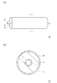
- FIG. 1 is a schematic external view (a) of a charging roll for electrophotographic equipment according to one embodiment of the present invention, and a cross-sectional view (b) taken along line AA thereof.
- FIG. It is an enlarged sectional view of a roll surface.
- FIG. 1 is a schematic external view (a) of a charging roll for electrophotographic equipment according to one embodiment of the present invention and a cross-sectional view (b) taken along the line AA.
- FIG. 2 is an enlarged cross-sectional view of the roll surface.
- the charging roll 10 includes a shaft 12 , an elastic layer 14 formed on the outer peripheral surface of the shaft 12 , and a surface layer 16 formed on the outer peripheral surface of the elastic layer 14 .
- the elastic layer 14 is a layer (base layer) that serves as the base of the charging roll 10 .
- the surface layer 16 is a layer that appears on the surface of the charging roll 10 .
- an intermediate layer such as a resistance adjusting layer may be formed between the elastic layer 14 and the surface layer 16 if necessary.
- the shaft 12 is not particularly limited as long as it has conductivity. Specifically, solid bodies made of metals such as iron, stainless steel and aluminum, core metals made of hollow bodies, and the like can be exemplified. An adhesive, a primer, or the like may be applied to the surface of the shaft 12, if necessary. That is, the elastic layer 14 may be adhered to the shaft 12 via an adhesive layer (primer layer). Adhesives, primers and the like may be made conductive as necessary.
- the elastic layer 14 contains silicone rubber. Since the silicone rubber is soft, the toner in contact with the charging roll 10 is less likely to be crushed, so that the surface of the roll can be prevented from being soiled due to crushing of the toner. On the other hand, since the silicone rubber is soft, the charging roll 10 tends to have a large contact area with the photoreceptor. And silicone rubber is weak against tearing force. As a result, the elastic layer 14 of the charging roll 10 is easily torn and broken due to the stress during driving. Further, since the silicone rubber is soft, it is difficult for a gap to form between the charging roll 10 and the photosensitive member. As a result, the amount of discharge is reduced, so there is a risk that the chargeability will be reduced.
- the outer peripheral surface of the elastic layer 14 containing silicone rubber is formed into a specific shape, and a specific surface layer 16 containing urethane polymer is provided on the outer peripheral surface of the elastic layer 14. It is configured.
- the elastic layer 14 has a plurality of large projections 18a with a width of 13 ⁇ m or more and 48 ⁇ m or less and a height of 5 ⁇ m or more and 13 ⁇ m or less on its outer peripheral surface. It has a plurality of small projections 18b forming irregularities with a point average roughness Rz of 1.0 ⁇ m or more and 6.0 ⁇ m or less. Since the elastic layer 14 has a plurality of large protrusions 18a on its outer peripheral surface, the roll surface is formed with a roughness that ensures sufficient discharge. Thereby, chargeability can be ensured. By doing so, it is easy to suppress the occurrence of a fog image. In addition, by having a plurality of small protrusions 18b on the surface of the large protrusion 18a, the elastic layer 14 has a large contact area with the surface layer 16, and peeling of the surface layer 16 from the elastic layer 14 is easily suppressed.
- the width w of the large protrusions 18a is less than 13 ⁇ m, the width w of the large protrusions 18a is too narrow, and the contact area of the elastic layer 14 that contacts the photoreceptor through the surface layer 16 of the large protrusions 18a is reduced. The effect is small, and the elastic layer 14 is torn and broken by stress during driving. From the viewpoint of suppressing breakage of the elastic layer 14 during driving, the width w of the large protrusion 18a is preferably 15 ⁇ m or more, more preferably 20 ⁇ m or more, and even more preferably 25 ⁇ m or more.
- the width w of the large protrusions 18a is more than 48 ⁇ m, the contact area of the large protrusions 18a contacting the photoreceptor through the surface layer 16 is too large, and the large protrusions 18a are torn by the stress during driving. rupture.
- the width w of the large protrusion 18a is preferably 45 ⁇ m or less, more preferably 40 ⁇ m or less.
- the height h of the large projections 18a is less than 5 ⁇ m, the roll surface will not be rough enough to ensure sufficient discharge, and the chargeability will not be satisfactory.
- the height h of the large projections 18a is preferably 6 ⁇ m or more, more preferably 7 ⁇ m or more, from the viewpoint of excellent chargeability.
- the height h of the large protrusion 18a is more than 13 ⁇ m, the large protrusion 18a is too high, and the elastic layer 14 is torn at the base of the large protrusion 18a. As a result, the chargeability is unsatisfactory.
- the height h of the large protrusions 18a is preferably 12 ⁇ m or less, more preferably 10 ⁇ m or less.
- the ten-point average roughness Rz of the surface of the large protrusions 18a formed by the plurality of small protrusions 18b is less than 1.0 ⁇ m, the surface roughness of the large protrusions 18a is insufficient, and peeling of the surface layer 16 is suppressed. do not have.
- the ten-point average roughness Rz is preferably 1.5 ⁇ m or more, more preferably 2.0 ⁇ m or more.
- the ten-point average roughness Rz is more than 6.0 ⁇ m, the small protrusions 18b are too large, and the elastic layer 14 is torn at the roots of the small protrusions 18b.
- the ten-point average roughness Rz is preferably 5.5 ⁇ m or less, more preferably 5.0 ⁇ m or less.
- Roughness Rz is a ten-point average roughness, and is the average value of values measured at arbitrary five locations in accordance with JIS B0601 (1994).
- the ten-point average roughness Rz of the surface of the large projections 18a formed by the plurality of small projections 18b can be measured by observation using a laser microscope (for example, "VK-9510" manufactured by Keyence).
- the surface layer 16 contains urethane polymer.
- the surface layer 16 containing the urethane polymer has an elongation at break of 285% or more and 525% or less.
- the surface layer 16 and the elastic layer 14 move by using a relatively stretchable urethane polymer as the material of the surface layer 16 and approximating the stretch and hardness of the surface layer 16 to the stretch and hardness of the elastic layer 14 containing silicone rubber. are integrated, and the surface layer 16 follows the movement of the elastic layer 14, so that the tearing weakness of the elastic layer 14 due to the silicone rubber can be improved.
- the breaking elongation of the surface layer 16 is less than 285%, the surface layer 16 is too hard to follow the elastic layer 14, and the elastic layer 14 containing silicone rubber is torn and broken by the stress during driving. .
- the breaking elongation of the surface layer 16 is more preferably 300% or more, more preferably 320% or more, from the viewpoint of suppressing tearing rupture of the elastic layer 14 .
- the breaking elongation of the surface layer 16 exceeds 525%, the surface layer 16 is too soft and the elastic layer 14 cannot follow the surface layer 16, and only the surface layer 16 moves due to the stress during driving, and the elastic layer 14 moves from the surface layer. 16 is peeled off.
- the elongation at break of the surface layer 16 is preferably 500% or less, more preferably 450% or less, and even more preferably 400% or less from the viewpoint of suppressing peeling of the surface layer 16 .
- the surface layer 16 is preferably formed along the uneven surface formed by the plurality of small protrusions 18 b of the elastic layer 14 .
- the surface layer 16 is formed along the uneven surface formed by the plurality of small protrusions 18b of the elastic layer 14, the chargeability and surface unevenness can be maintained.
- the distance d1 between the large protrusions 18a is not particularly limited, but is preferably 25 ⁇ m or more and 55 ⁇ m or less. When the distance d1 between the large protrusions 18a is within the above range, it is possible to form moderate surface unevenness (roughness) by the plurality of large protrusions 18a. When the distance d1 between the large protrusions 18a is 25 ⁇ m or more, sufficient surface unevenness (roughness) is ensured, so that excellent discharge characteristics are maintained and chargeability is excellent. By doing so, it is easy to suppress the occurrence of a fog image. From this point of view, the distance d1 between the large protrusions 18a is preferably 27 ⁇ m or more, more preferably 30 ⁇ m or more.
- the distance d1 between the large protrusions 18a and the large protrusions 18a is 55 ⁇ m or less, the surface unevenness (roughness) is sufficiently ensured, so that the integration of the elastic layer 14 and the surface layer 16 is enhanced. , peeling of the surface layer 16 is easily suppressed.
- the distance d1 between the large protrusions 18a is preferably 50 ⁇ m or less, more preferably 45 ⁇ m or less.
- the distance d2 between the small protrusions 18b is not particularly limited, it is preferably 0.4 ⁇ m or more and 3.8 ⁇ m or less.
- the distance d2 between the small protrusions 18b is within the above range, the plurality of small protrusions 18b can be appropriately dispersed on the surface of the large protrusion 18a.
- the distance d2 between the small protrusions 18b is 0.4 ⁇ m or more, the surface layer 16 is easily formed along the uneven surface formed by the plurality of small protrusions 18b. The surface layer 16 can be covered without filling the unevenness of the elastic layer 14 due to the small protrusions 18b.
- the distance d2 between the small projections 18b is preferably 0.5 ⁇ m or more, more preferably 0.7 ⁇ m or more, and even more preferably 1.0 ⁇ m or more.
- the distance d2 between the small protrusions 18b is 3.8 ⁇ m or less, the plurality of small protrusions 18b are appropriately dispersed on the surface of the large protrusion 18a. Such stress is appropriately dispersed, and tearing and breaking of the small projections 18b can be easily suppressed.
- the distance d2 between the small projections 18b is preferably 3.5 ⁇ m or less, more preferably 3.0 ⁇ m or less.
- a concave portion is formed between the large convex portions 18a.
- the bottom surface of this recess may be a flat portion or a curved portion.
- a plurality of small protrusions 18b forming unevenness with a ten-point average roughness Rz of 1.0 ⁇ m or more and 6.0 ⁇ m or less. may be formed. In the uneven surface shown in FIG.
- a plurality of small protrusions 18 b are formed between the large protrusions 18 a and the large protrusions 18 a to form protrusions and recesses having a ten-point average roughness Rz of 1.0 ⁇ m or more and 6.0 ⁇ m or less. It is When the ten-point average roughness Rz is 1.0 ⁇ m or more, integration between the elastic layer 14 and the surface layer 16 is enhanced, and peeling of the surface layer 16 is easily suppressed. From this point of view, the ten-point average roughness Rz is more preferably 1.5 ⁇ m or more, and still more preferably 2.0 ⁇ m or more.
- the ten-point average roughness Rz is 6.0 ⁇ m or less, the discharge characteristics can be improved. From this point of view, the ten-point average roughness Rz is more preferably 5.5 ⁇ m or less, and even more preferably 5.0 ⁇ m or less.
- the elastic layer 14 has a plurality of large projections 18a and a plurality of small projections 18b on its outer peripheral surface, so that the outer peripheral surface has a large surface area.
- the surface area ratio S/So of the elastic layer 14 is not particularly limited, but is preferably 2.2 or more and 7.7 or less.
- the elastic layer 14 and the surface layer 16 are integrated with each other because the surface has moderate unevenness (roughness) due to the plurality of large protrusions 18a and the plurality of small protrusions 18b. is increased, and peeling of the surface layer 16 is easily suppressed. Also, excellent discharge characteristics can be maintained. By doing so, it is easy to suppress the occurrence of a fog image.
- the surface area ratio S/So is more preferably 2.5 or more and 7.0 or less, still more preferably 3.0 or more and 6.0 or less.
- S is the measured surface area of the elastic layer 14
- S0 is the theoretical surface area assuming that the surface of the elastic layer 14 is flat.
- the elastic layer 14 preferably has hydroxyl groups or hydroperoxy groups formed on its outer peripheral surface.
- the affinity between the elastic layer 14 and the urethane polymer is improved, and the surface layer 16 is easily formed along the uneven surface formed by the plurality of small protrusions 18b of the elastic layer 14. 16 can be coated.
- the integration of the elastic layer 14 and the surface layer 16 is enhanced, and peeling of the surface layer 16 is easily suppressed.
- hydroxy groups or hydroperoxy groups can be formed on the outer peripheral surface of the elastic layer 14 .
- the elastic layer 14 preferably has a surface hardness (MD-1 hardness) in the range of 30 to 55 degrees from the viewpoint of easily suppressing contamination of the roll surface due to toner crushing.
- the elastic layer 14 can be configured to have a lower hardness by including silicone rubber.
- the thickness of the surface layer 16 is preferably 0.1 ⁇ m or more and 2.0 ⁇ m or less.
- the thickness of the surface layer 16 is more preferably 0.2 ⁇ m or more, and still more preferably 0.5 ⁇ m or more.
- the thickness of the surface layer 16 is 2.0 ⁇ m or less, the surface roughness of the elastic layer 14 can be maintained without filling the surface unevenness. From this point of view, the thickness of the surface layer 16 is more preferably 1.7 ⁇ m or less, and even more preferably 1.5 ⁇ m or less.
- the affinity between the urethane polymer constituting the surface layer 16 and the elastic layer 14 is improved, and the surface layer 16 can be easily formed on the surface of the elastic layer 14 to be thinner. Further, when the small protrusions 18b of the elastic layer 14 are appropriately dispersed, the urethane polymer forming the surface layer 16 can easily permeate between the small protrusions 18b and the small protrusions 18b. It becomes easy to form the surface layer 16 without filling the concave portion due to the coating.
- the urethane polymer forming the surface layer 16 preferably has an NCO index of 100 or more and 150 or less.
- NCO index 100 or more
- the surface layer 16 is not too soft and the elastic layer 14 easily follows the surface layer 16 .
- the NCO index is 150 or less
- the surface layer 16 is not too hard, and the surface layer 16 easily follows the elastic layer 14 .
- the NCO index of the urethane polymer is more preferably 110 or more and 140 or less, still more preferably 120 or more and 135 or less from the above viewpoint.
- the NCO index is expressed in equivalents of isocyanate groups of the isocyanate per 100 total equivalents of hydroxyl groups of the polyol.
- the urethane polymer forming the surface layer 16 can be formed from a urethane composition containing polyol and isocyanate.
- the urethane composition may consist of only a thermosetting urethane polymer, or may contain a thermoplastic urethane polymer in addition to the thermosetting urethane polymer.
- the thermoplastic urethane polymer is included, the elongation of the material increases.
- the integration of layer 14 and surface layer 16 can be facilitated to be enhanced.
- the elongation at break of the surface layer 16 can be easily kept within a specific range.
- Thermoplastic urethane polymers include caprolactone, adipate, and ether types.
- the caprolactone type is preferable from the viewpoint of ensuring high mechanical strength and elastic recovery. As a result, high mechanical strength can be obtained with low hardness.
- the molecular weight is preferably relatively large. A preferred molecular weight range is from 10,000 to 500,000.
- thermosetting urethane polymer and the thermoplastic urethane polymer is preferably in the range of 20/80 to 80/20 in mass ratio.
- the mixing ratio is within this range, the balance between coatability, low hardness, and permanent set resistance is excellent. More preferably, it is within the range of 40/60 to 60/40.
- the polyol that constitutes the urethane polymer preferably has 2 to 3 functional groups. More preferably, it has two functional groups. When the number of functional groups of the polyol constituting the urethane polymer is 2, the hardness of the surface layer 16 is suppressed, and the integration of the elastic layer 14 and the surface layer 16 is enhanced, so peeling of the surface layer 16 is easily suppressed.
- the polyol constituting the urethane polymer preferably has a molecular weight of 100 to 1000, 100 to 750, 100 to 500, etc. from the viewpoint of permeability into the elastic layer 14 and the like.
- Polyols constituting the urethane polymer include diols such as ethylene glycol, diethylene glycol, triethylene glycol, propylene glycol, polypropylene glycol, dipropylene glycol, butylene glycol, neopentyl glycol, 1,6-hexylene glycol, trimethylolethane, Examples include triols such as trimethylolpropane, hexanetriol, and glycerin. These may be used singly or in combination of two or more as the polyol constituting the urethane polymer. Among these, diols such as 1,6-hexylene glycol are particularly preferable from the viewpoint of ease of control of the cross-linking reaction.
- the isocyanate that constitutes the urethane polymer preferably has 2 to 3 functional groups. More preferably, it has two functional groups. When the number of functional groups of the isocyanate constituting the urethane polymer is 2, the hardness of the surface layer 16 is suppressed, and the integration of the elastic layer 14 and the surface layer 16 is enhanced, so peeling of the surface layer 16 is easily suppressed.
- the isocyanate constituting the urethane polymer may be a prepolymer having an isocyanate group at its terminal, or may not be a prepolymer.
- the isocyanate constituting the urethane polymer preferably has a molecular weight of 100 to 1000, 100 to 750, 100 to 500, etc. from the viewpoint of permeability into the elastic layer .
- Isocyanates constituting the urethane polymer include 4,4′-diphenylmethane diisocyanate (MDI), isophorone diisocyanate (IPDI), 4,4′-dicyclohexylmethane diisocyanate (hydrogenated MDI), trimethylhexamethylene diisocyanate (TMHDI), tolylene isocyanate (TDI), carbodiimide-modified MDI, polymethylene phenyl isocyanate (PAPI), orthotoluidine diisocyanate (TODI), naphthylene diisocyanate (NDI), xylene diisocyanate (XDI), hexamethylene diisocyanate (HMDI), paraphenylene diisocyanate (PDI) , lysine diisocyanate methyl ester (LDI), dimethyl diisocyanate (DDI), and the like. These may be used singly or in combination of two or more as the isocyanate constituting
- the urethane composition may contain a solvent together with the urethane composition containing polyol and isocyanate. By including the solvent, the solid content concentration can be adjusted, and the thickness of the surface layer 16 can be adjusted. Moreover, it makes it easier to form the surface layer 16 more uniformly.
- the solid content concentration in the urethane composition is preferably in the range of 1% by mass or more and 40% by mass or less from the viewpoint of permeability, thickness, and the like. More preferably, it is 3% by mass or more and 35% by mass or less.
- Solvents include acetone, methyl ethyl ketone, methyl isobutyl ketone, xylene, hexane, petroleum ether, normal hexane, cyclohexane, benzene, toluene, methyl acetate, ethyl acetate, butyl acetate, ethyl ether, dichloromethane, tetrahydrofuran, gasoline, petroleum ether, and benzine. , dimethylformamide, and the like. These solvents may be used singly or in combination of two or more. Among these, methyl ethyl ketone (MEK) is particularly preferred from the viewpoint of material solubility and volatility.
- MEK methyl ethyl ketone
- a conductive agent can be added to the elastic layer 14 to impart conductivity.
- conductive agents include electronic conductive agents and ionic conductive agents.
- Electronic conductors include carbon black, graphite, and conductive metal oxides.
- Conductive metal oxides include conductive titanium oxide, conductive zinc oxide, conductive tin oxide, and the like.
- ion conductive agents include quaternary ammonium salts, borates, surfactants, and the like.
- various additives may be appropriately added to the elastic layer 14 as necessary.
- Additives include lubricants, vulcanization accelerators, antioxidants, light stabilizers, viscosity modifiers, processing aids, flame retardants, plasticizers, foaming agents, fillers, dispersants, antifoaming agents, pigments, release agents, Molding agents and the like can be mentioned.
- the elastic layer 14 can be adjusted to have a predetermined volume resistivity by adjusting the amount of the ionic conductive agent, the electronic conductive agent, and the like.
- the volume resistivity of the elastic layer 14 may be appropriately set in the range of 10 2 to 10 10 ⁇ cm, 10 3 to 10 9 ⁇ cm, 10 4 to 10 8 ⁇ cm.
- the thickness of the elastic layer 14 is not particularly limited, and may be appropriately set within the range of 0.1 to 10 mm.
- a conductive agent can be added to the surface layer 16 to impart conductivity.
- conductive agents include electronic conductive agents and ionic conductive agents.
- Electronic conductors include carbon black, graphite, and conductive metal oxides.
- Conductive metal oxides include conductive titanium oxide, conductive zinc oxide, conductive tin oxide, and the like.
- ion conductive agents include quaternary ammonium salts, borates, surfactants, and the like.
- various additives may be appropriately added to the surface layer 16 as necessary. Examples of additives include plasticizers, leveling agents, fillers, vulcanization accelerators, processing aids, release agents, and the like.
- the volume resistivity of the surface layer 16 is preferably set in a semi-conductive region from the viewpoint of chargeability. Specifically, for example, it may be set within the range of 1.0 ⁇ 10 7 to 1.0 ⁇ 10 10 ⁇ cm. Volume resistivity can be measured according to JIS K6911.
- the elastic layer 14 is formed by placing the shaft 12 coaxially in the hollow part of the roll molding mold, injecting an uncrosslinked silicone rubber composition, heating and curing (crosslinking), and then demolding. can be formed by
- the large convex portion 18a of the elastic layer 14 can be formed by mold transfer. It is preferable to form a predetermined concave-convex shape on the inside of the roll forming mold (inside surface of the mold).
- the small protrusions 18b of the elastic layer 14 can be formed by subjecting the outer peripheral surface of the elastic layer 14 to surface treatment.
- Such surface treatments include corona treatment, plasma treatment, UV treatment, electron beam treatment, excimer treatment, and flame treatment.
- excimer treatment, corona treatment, and the like are preferable from the viewpoint of forming fine unevenness.
- functional groups such as hydroxyl groups and hydroperoxy groups can be formed on the outer peripheral surface of the elastic layer 14 by surface treatment. These functional groups contribute to adhesion between the material of the elastic layer 14 and the material of the surface layer 16 .
- the material of the surface layer 16 can easily enter into the concave portions of the fine surface unevenness formed by the large convex portions 18a and the small convex portions 18b, and the fine surface unevenness of the outer peripheral surface of the elastic body layer 14 can be maintained and the thin surface layer 16 can be formed. becomes easier to form.
- the surface layer 16 can be formed by using a material for forming the surface layer 16, coating it on the outer peripheral surface of the elastic layer 14, and appropriately performing a drying treatment or the like.
- the surface layer 16 can be formed along the uneven surface formed by the plurality of small protrusions 18 b of the elastic layer 14 .
- the shaft 12, the elastic layer 14 formed on the outer peripheral surface of the shaft 12, and the surface layer 16 formed on the outer peripheral surface of the elastic layer 14 are provided.
- the elastic layer 14 contains a silicone polymer, and the outer peripheral surface of the elastic layer 14 has a plurality of large protrusions 18a with a width of 13 ⁇ m or more and 48 ⁇ m or less and a height of 5 ⁇ m or more and 13 ⁇ m or less.
- the surface has a plurality of small protrusions 18b forming unevenness with a ten-point average roughness Rz of 1.0 ⁇ m or more and 6.0 ⁇ m or less, the surface layer 16 contains a urethane polymer, and the breaking elongation of the surface layer 16 is 285. % or more and 525% or less, toner contamination, tearing breakage of the elastic layer 14, and peeling of the surface layer 16 are suppressed, and the chargeability is excellent.
- the large convex portion 18a is shown as having a hemispherical cross section in FIG. 2, the shape of the large convex portion 18a is not particularly limited. Various shapes such as a hemispherical cross section, a triangular cross section, and a square cross section are possible.
- the plurality of large projections 18a may be scattered on the outer peripheral surface of the elastic layer 14 in an island-like manner, or may be continuous in the axial direction, the circumferential direction, or the direction in between, for example. It may be formed into filaments.
- the elastic layer composition was injected into a cylindrical mold coaxially set with a conductive shaft ( ⁇ 6 mm), heated at 150° C. for 30 minutes, cooled, and demolded. As a result, a roll body having an elastic layer of 3 mm thickness on the outer periphery of the conductive shaft was produced. A concave-convex shape was formed inside the mold, and a plurality of large convex portions were formed on the outer peripheral surface of the roll by mold transfer. The plurality of large projections are scattered in an island shape on the outer peripheral surface of the roll body.
- a plurality of small projections were formed on the surfaces of the plurality of large projections by applying an excimer treatment (600 mW/cm 2 , irradiation for 120 seconds) to the outer peripheral surface of the produced roll body.
- the plurality of small protrusions are scattered in an island shape on the surface of the large protrusion and on the recesses between the large protrusions.
- ⁇ Preparation of surface layer composition Thermoplastic urethane polymer ("N5196” manufactured by Nippon Polyurethane) 50 parts by mass, ether-based polyol ("PPG2000” manufactured by Sanyo Kasei) 30 parts by mass, and isocyanate ("Barnock DN955" manufactured by Dainippon Ink and Chemicals) 20 parts by mass , After kneading 30 parts by mass of an electronic conductive agent ("Denka Black” manufactured by Denki Kagaku Kogyo Co., Ltd.) and 1 part by mass of an ion conductive agent (quaternary ammonium salt) in a ball mill, 400 parts by mass of MEK is added and mixed and stirred.
- a surface layer composition was prepared by the following.
- a surface layer composition was applied to the outer peripheral surface of the elastic layer after the surface treatment by a roll coating method, and then heat-treated at 170° C. for 60 minutes to form a surface layer. Thus, a charging roll was produced.
- Examples 2 to 14, 21 to 26, Comparative Examples 1 to 8 A roll body was produced in the same manner as in Example 1, except that the uneven shape inside the mold was changed. Then, the surface treatment of the elastic layer and the preparation of the surface layer were carried out in the same manner as in Example 1 to prepare a charging roll.
- Example 15 A roll body was produced in the same manner as in Example 1, except that the uneven shape inside the mold was changed. Next, the surface treatment method of the elastic layer was changed, and the surface layer was produced in the same manner as in Example 1, thereby producing a charging roll.
- Examples 16-17 Comparative Examples 9-10
- a roll body was produced in the same manner as in Example 1, except that the uneven shape inside the mold was changed.
- the surface treatment of the elastic layer was performed in the same manner as in Example 1.
- the composition of the surface layer composition was changed, the surface layer was produced, and the charging roll was produced.
- Example 18-19, 28-29 A roll body was produced in the same manner as in Example 1, except that the uneven shape inside the mold was changed. Then, the surface treatment of the elastic layer was performed in the same manner as in Example 1. Next, the thickness of the surface layer was changed, the surface layer was manufactured, and the charging roll was manufactured.
- Example 20 and 30 A roll body was produced in the same manner as in Example 1, except that the uneven shape inside the mold was changed. Then, the surface treatment of the elastic layer was performed in the same manner as in Example 1. Next, in the preparation of the surface layer composition, the polyol was changed from an ether-based polyol (“PPG2000” manufactured by Sanyo Chemical Industries) to an ethylenediamine-based polyol (“Newpol NP-300” manufactured by Sanyo Chemical Industries) to prepare a surface layer, and a charging roll was prepared. was made.
- PPG2000 ether-based polyol
- Newpol NP-300 manufactured by Sanyo Chemical Industries
- Example 27 A roll body was produced in the same manner as in Example 1, except that the uneven shape inside the mold was changed. Next, the surface layer was prepared in the same manner as in Example 1 without surface treatment of the elastic layer, thereby preparing a charging roll.
- the uneven shape of the elastic layer of the charging roll was investigated. Also, the elongation at break of the surface layer material and the thickness of the surface layer were measured. In addition, the tear strength of the elastic layer of the charging roll, peeling of the surface layer, chargeability, and contamination were evaluated.
- the surface roughness Rz is a 10-point average roughness, and is the average value of values measured at arbitrary five points in accordance with JIS B0601 (1994).
- the surface roughness Rz of concave portions between large convex portions was measured by observation using a laser microscope ("VK-9510" manufactured by Keyence). In the photographed image, the value calculated by selecting a groove of 0.01 mm 2 in the surface roughness mode in the analysis program (program name: KEYENCE VK Analyzer analysis application) was defined as the surface roughness Rz of the concave portion.
- the produced charging roll was attached to a cartridge (black) of an actual machine ("CLJ4525dn” manufactured by HP), and after running 30,000 sheets in an environment of 15° C. ⁇ 10% RH, the appearance of the roll was visually observed. At this time, tearing of the elastic layer of the charging roll was confirmed, and the image was affected. ⁇ ”, and very good “ ⁇ ” when no tearing was observed and the image was not affected.
- the produced charging roll was attached to a cartridge (black) of an actual machine ("CLJ4525dn” manufactured by HP), and after running 30,000 sheets in an environment of 15° C. ⁇ 10% RH, the appearance of the roll was visually observed. At this time, peeling of the surface layer of the charging roll was confirmed, and the image was affected. A case in which there was no effect on the image without any confirmation was evaluated as "very good”.
- the prepared charging roll was attached to the cartridge (black) of the actual machine ("CLJ4525dn" made by HP), and an image was produced in a 25% density halftone under an environment of 15°C and 10% RH. made an evaluation.
- An image without black spots (fogging) was rated as very good ( ⁇ ), black spots that occurred but were light in density and acceptable were rated as good ( ⁇ ), and black dots with unacceptable density were rated as bad (x).
- Comparative Example 1 since the width of the large protrusion was too large, the contact area of the large protrusion contacting the photoreceptor through the surface layer was too large, and the large protrusion was torn and broken at the base. In Comparative Example 2, since the width of the large protrusions was too small, the effect of surface unevenness due to the large protrusions was small, and the contact area of the elastic layer in contact with the photoreceptor via the surface layer was too large, causing the elastic layer to tear. and broke. In Comparative Example 3, since the height of the large protrusion was too high, the large protrusion was torn and broken at the base. In addition, as a result, discharge characteristics deteriorated, and a black dot image was generated.
- Comparative Example 4 since the height of the large convex portion was too low, the roughness was insufficient, and the charging was insufficient due to insufficient discharge, resulting in deterioration of the image.
- Comparative Example 5 since the roughness of the surface of the large protrusion due to the small protrusion was too large, the small protrusion was torn at the base and broken.
- Comparative Example 6 since the roughness of the surface of the large projections due to the small projections was too small, the integration of the elastic layer and the surface layer was low, and the surface layer peeled off during durability.
- Comparative Example 9 the breaking elongation of the surface layer is too large, and only the surface layer is stretched by the force received at the contact portion with the photoreceptor, and the elastic layer does not follow the movement of the surface layer. Therefore, the surface layer peeled off during durability.
- Comparative Example 10 the breaking elongation of the surface layer is too small, and the surface layer does not follow the movement of the elastic layer. Therefore, the elastic layer was torn and broken during durability.
- the elastic layer contains a silicone polymer
- the outer peripheral surface of the elastic layer has a plurality of large protrusions having a width of 13 ⁇ m or more and 48 ⁇ m or less and a height of 5 ⁇ m or more and 13 ⁇ m or less. It has a plurality of small projections forming unevenness with a ten-point average roughness Rz of 1.0 ⁇ m or more and 6.0 ⁇ m or less, a surface layer containing a urethane polymer, and a breaking elongation of the surface layer of 285% or more and 525% or less. Further, according to the examples, the tearing breakage of the elastic layer, the peeling of the surface layer, and the toner contamination are suppressed. In addition, it is excellent in chargeability.
- the tearing breakage of the elastic layer can be further improved.
- the width of the large protrusions For example, by setting the width of the large protrusions to 15 ⁇ m or more and 45 ⁇ m or less, the height of the large protrusions to 12 ⁇ m or less, and the roughness Rz of the surface of the large protrusions to 5.5 ⁇ m or less, the tear rupture of the elastic layer is further improved. (Examples 1-3, 5, 7-12). Also, it can be seen that the chargeability can be further improved by adjusting the height of the large projections.
- the chargeability of the elastic layer can be further improved (Examples 3 to 4, 7 to 12).
- peeling of the surface layer can be further improved by adjusting the roughness Rz of the surface of the large protrusions. For example, by setting the roughness Rz of the surface of the large projections to 1.5 ⁇ m or more, peeling of the surface layer can be further improved (Examples 6, 7 to 12).
- Examples 7-8 and Examples 21-22 it can be seen that peeling of the surface layer and electrification properties can be further improved when the distance between the large protrusions is 25 ⁇ m or more and 55 ⁇ m or less.
- Examples 9-10 and Examples 22-24 when the distance between the small protrusions is 0.4 ⁇ m or more and 3.8 ⁇ m or less, tearing of the elastic layer and peeling of the surface layer are further improved. I know you can.
- Examples 11 and 12 with Examples 25 and 26 when the roughness Rz of the surface of the concave portions between the large convex portions is 1.0 ⁇ m or more and 6.0 ⁇ m or less, the peeling of the surface layer and the chargeability are further improved.
- charging roll 12 shaft 14 elastic layer 16 surface layer 18a large convex portion 18b small convex portion w width of large convex portion h height of large convex portion d1 distance between large convex portions d2 distance between small convex portions
Landscapes
- Physics & Mathematics (AREA)
- Engineering & Computer Science (AREA)
- Plasma & Fusion (AREA)
- General Physics & Mathematics (AREA)
- Electrostatic Charge, Transfer And Separation In Electrography (AREA)
Abstract
Description
本発明は、電子写真方式を採用する複写機、プリンター、ファクシミリなどの電子写真機器において好適に用いられる電子写真機器用帯電ロールに関するものである。 The present invention relates to a charging roll for electrophotographic equipment that is suitably used in electrophotographic equipment such as copiers, printers and facsimiles that employ an electrophotographic system.
電子写真機器の帯電ロールとしては、芯金などの軸体の外周面上にゴム弾性を有する弾性体層を有し、その弾性体層の外周面上に表層を有するものが知られている。帯電ロールにおいて、弾性体層の材料としてシリコーンゴムを用いることが知られている(特許文献1)。 As a charging roll for electrophotographic equipment, one having an elastic layer having rubber elasticity on the outer peripheral surface of a shaft such as a core metal and a surface layer on the outer peripheral surface of the elastic layer is known. In charging rolls, it is known to use silicone rubber as a material for the elastic layer (Patent Document 1).
シリコーンゴムが軟らかいことから、帯電ロールに接するトナーは潰れにくく、トナー潰れによるロール表面の汚れは抑えられやすい。一方で、その軟らかさ故に帯電ロールと感光体の接触面積は大きくなりやすい。そして、シリコーンゴムは引き裂き力に弱い。これらにより、感光体に接する帯電ロールは駆動時の応力で弾性体層が引き裂かれ、破断しやすい。また、その軟らかさ故に帯電ロールと感光体との間に空隙はできにくく、放電量が少なくなるため、帯電性が低下する。このため、帯電ロールでは、トナー汚れの抑制、弾性体層の引き裂きによる破断の抑制、良好な帯電性を満足することが求められる。また、弾性体層の外周面上に表層を形成する場合、弾性体層から表層の剥がれが問題となる。 Because the silicone rubber is soft, the toner in contact with the charging roll is less likely to be crushed, and contamination on the roll surface due to toner crushing is easily suppressed. On the other hand, due to its softness, the contact area between the charging roll and the photosensitive member tends to increase. And silicone rubber is weak against tearing force. As a result, the elastic layer of the charging roll in contact with the photoreceptor is torn due to the stress during driving, and the charging roll is likely to be broken. In addition, due to its softness, it is difficult for a gap to form between the charging roll and the photoreceptor, and the amount of discharge is reduced, resulting in a decrease in chargeability. For this reason, the charging roll is required to satisfy suppression of toner contamination, suppression of breakage due to tearing of the elastic layer, and satisfactory charging performance. Moreover, when forming the surface layer on the outer peripheral surface of the elastic layer, peeling of the surface layer from the elastic layer poses a problem.
本発明が解決しようとする課題は、トナー汚れ、弾性体層の引き裂き破断、表層の剥がれが抑えられるとともに帯電性に優れる電子写真機器用帯電ロールを提供することにある。 The problem to be solved by the present invention is to provide a charging roll for electrophotographic equipment that suppresses toner contamination, tearing and rupture of the elastic layer, and peeling of the surface layer, and has excellent charging properties.
本発明に係る電子写真機器用帯電ロールは、軸体と、前記軸体の外周面上に形成された弾性体層と、前記弾性体層の外周面上に形成された表層と、を備え、前記弾性体層が、シリコーンゴムを含み、前記弾性体層の外周表面に、幅13μm以上48μm以下で高さ5μm以上13μm以下の複数の大凸部を有するとともに、前記大凸部の表面に、十点平均粗さRzが1.0μm以上6.0μm以下の凹凸を形成する複数の小凸部を有し、前記表層が、ウレタンポリマーを含み、前記表層の破断伸びが、285%以上525%以下である。 A charging roll for electrophotographic equipment according to the present invention comprises a shaft, an elastic layer formed on the outer peripheral surface of the shaft, and a surface layer formed on the outer peripheral surface of the elastic layer, The elastic layer contains silicone rubber, and has a plurality of large projections having a width of 13 μm or more and 48 μm or less and a height of 5 μm or more and 13 μm or less on the outer peripheral surface of the elastic layer, and the surfaces of the large projections are: It has a plurality of small projections forming unevenness with a ten-point average roughness Rz of 1.0 μm or more and 6.0 μm or less, the surface layer contains a urethane polymer, and the breaking elongation of the surface layer is 285% or more and 525%. It is below.
前記ウレタンポリマーのNCOインデックスは、100以上150以下であることが好ましい。前記表層の厚さは、0.1μm以上2.0μm以下であることが好ましい。前記表層は、前記弾性体層の複数の小凸部で形成された凹凸面に沿って形成されていることが好ましい。前記弾性体層の外周表面に、ヒドロキシ基またはヒドロペルオキシ基が形成されていることが好ましい。前記大凸部と前記大凸部の間の表面に、十点平均粗さRzが1.0μm以上6.0μm以下の凹凸を形成する複数の小凸部を有することが好ましい。前記大凸部と前記大凸部の間の距離は、25μm以上55μm以下であることが好ましい。前記小凸部と前記小凸部の間の距離は、0.4μm以上3.8μm以下であることが好ましい。前記弾性体層の表面積比S/Soは、2.2以上7.7以下であることが好ましい。前記ウレタンポリマーを構成するポリオールの官能基数は、2であることが好ましい。前記弾性体層の外周表面は、エキシマ処理またはコロナ処理が施されていることが好ましい。 The NCO index of the urethane polymer is preferably 100 or more and 150 or less. The thickness of the surface layer is preferably 0.1 μm or more and 2.0 μm or less. It is preferable that the surface layer is formed along an uneven surface formed by a plurality of small projections of the elastic layer. It is preferable that a hydroxy group or a hydroperoxy group is formed on the outer peripheral surface of the elastic layer. It is preferable that a plurality of small projections forming irregularities having a ten-point average roughness Rz of 1.0 μm or more and 6.0 μm or less be provided on the surface between the large projections. It is preferable that the distance between the large protrusions is 25 μm or more and 55 μm or less. It is preferable that the distance between the small protrusions is 0.4 μm or more and 3.8 μm or less. The surface area ratio S/So of the elastic layer is preferably 2.2 or more and 7.7 or less. The number of functional groups of the polyol constituting the urethane polymer is preferably two. The outer peripheral surface of the elastic layer is preferably subjected to excimer treatment or corona treatment.
本発明に係る電子写真機器用帯電ロールによれば、軸体と、前記軸体の外周面上に形成された弾性体層と、前記弾性体層の外周面上に形成された表層と、を備え、前記弾性体層が、シリコーンゴムを含み、前記弾性体層の外周表面に、幅13μm以上48μm以下で高さ5μm以上13μm以下の複数の大凸部を有するとともに、前記大凸部の表面に、十点平均粗さRzが1.0μm以上6.0μm以下の凹凸を形成する複数の小凸部を有し、前記表層が、ウレタンポリマーを含み、前記表層の破断伸びが、285%以上525%以下であることから、トナー汚れ、弾性体層の引き裂き破断、表層の剥がれが抑えられるとともに帯電性に優れる。 According to the charging roll for an electrophotographic apparatus according to the present invention, a shaft, an elastic layer formed on the outer peripheral surface of the shaft, and a surface layer formed on the outer peripheral surface of the elastic layer are provided. wherein the elastic layer contains silicone rubber, and a plurality of large protrusions having a width of 13 μm or more and 48 μm or less and a height of 5 μm or more and 13 μm or less are provided on the outer peripheral surface of the elastic layer, and the surfaces of the large protrusions. has a plurality of small protrusions forming unevenness with a ten-point average roughness Rz of 1.0 μm or more and 6.0 μm or less, the surface layer contains a urethane polymer, and the breaking elongation of the surface layer is 285% or more. Since it is 525% or less, it is possible to suppress toner contamination, tear breakage of the elastic layer, and peeling of the surface layer, and to achieve excellent charging properties.
前記ウレタンポリマーのNCOインデックスが100以上150以下であると、表層の破断伸びが特定範囲内に収まりやすい。これにより、弾性体層が表層に追従しやすく、また、表層が弾性体層に追従しやすい。そうすると、弾性体層の引き裂き破断が抑えられやすく、表層の剥がれが抑えられやすい。 When the NCO index of the urethane polymer is 100 or more and 150 or less, the elongation at break of the surface layer tends to fall within a specific range. Thereby, the elastic layer easily follows the surface layer, and the surface layer easily follows the elastic layer. By doing so, it is easy to suppress tearing and breaking of the elastic layer, and it is easy to suppress peeling of the surface layer.
前記表層の厚さが0.1μm以上2.0μm以下であると、帯電性および表面粗さが維持されやすい。 When the thickness of the surface layer is 0.1 μm or more and 2.0 μm or less, the chargeability and surface roughness are easily maintained.
前記表層が前記弾性体層の複数の小凸部で形成された凹凸面に沿って形成されていると、帯電性および表面粗さが維持されやすい。 When the surface layer is formed along the uneven surface formed by the plurality of small projections of the elastic layer, the chargeability and surface roughness are easily maintained.
前記弾性体層の外周表面にヒドロキシ基またはヒドロペルオキシ基が形成されていると、弾性体層とウレタンポリマーの親和性が向上し、弾性体層の複数の小凸部で形成された凹凸面に沿って表層が形成されやすくなり、弾性体層の表面凹凸を埋めないで表層を被覆することができる。また、弾性体層と表層の一体化が高められ、表層の剥がれが抑えられやすい。 When a hydroxy group or a hydroperoxy group is formed on the outer peripheral surface of the elastic layer, the affinity between the elastic layer and the urethane polymer is improved, and the uneven surface formed by a plurality of small protrusions of the elastic layer The surface layer is easily formed along the elastic layer, and the surface layer can be covered without filling the surface unevenness of the elastic layer. In addition, the integration of the elastic layer and the surface layer is enhanced, and peeling of the surface layer is easily suppressed.
前記大凸部と前記大凸部の間の表面に十点平均粗さRzが1.0μm以上6.0μm以下の凹凸を形成する複数の小凸部を有すると、放電特性を向上することができる。また、弾性体層と表層の一体化が高められ、表層の剥がれが抑えられやすい。 If the surface between the large protrusions and the large protrusions has a plurality of small protrusions forming unevenness with a ten-point average roughness Rz of 1.0 μm or more and 6.0 μm or less, discharge characteristics can be improved. can. In addition, the integration of the elastic layer and the surface layer is enhanced, and peeling of the surface layer is easily suppressed.
前記大凸部と前記大凸部の間の距離が25μm以上55μm以下であると、複数の大凸部による適度な表面凹凸(粗さ)が形成されるため、弾性体層と表層の一体化が高められ、表層の剥がれが抑えられやすい。また、優れた放電特性を維持することができる。そうすると、カブリ画像の発生が抑えられやすい。 When the distance between the large protrusions is 25 μm or more and 55 μm or less, moderate surface irregularities (roughness) are formed by the plurality of large protrusions, so that the elastic layer and the surface layer are integrated. is increased, and peeling of the surface layer is easily suppressed. Also, excellent discharge characteristics can be maintained. By doing so, it is easy to suppress the occurrence of a fog image.
前記小凸部と前記小凸部の間の距離が0.4μm以上3.8μm以下であると、大凸部の表面に複数の小凸部が適度に分散するため、小凸部にかかる応力が適度に分散され、小凸部の引き裂き破断が抑えられやすい。また、弾性体層の複数の小凸部で形成された凹凸面に沿って表層が形成されやすくなり、凹凸を埋めないで表層を被覆することができる。また、弾性体層と表層の一体化が高められ、表層の剥がれが抑えられやすい。 When the distance between the small protrusions and the small protrusions is 0.4 μm or more and 3.8 μm or less, the plurality of small protrusions are appropriately dispersed on the surface of the large protrusions, so the stress applied to the small protrusions is is moderately dispersed, and tearing and breaking of small protrusions is easily suppressed. In addition, the surface layer is easily formed along the uneven surface formed by the plurality of small projections of the elastic layer, so that the surface layer can be covered without filling the unevenness. In addition, the integration of the elastic layer and the surface layer is enhanced, and peeling of the surface layer is easily suppressed.
前記弾性体層の表面積比S/Soが2.2以上7.7以下であると、複数の大凸部および複数の小凸部による適度な表面凹凸(粗さ)を有することから、弾性体層と表層の一体化が高められ、表層の剥がれが抑えられやすい。また、優れた放電特性を維持することができる。そうすると、カブリ画像の発生が抑えられやすい。 When the surface area ratio S/So of the elastic layer is 2.2 or more and 7.7 or less, the elastic layer has an appropriate surface unevenness (roughness) due to a plurality of large protrusions and a plurality of small protrusions. The integration of the layer and the surface layer is enhanced, and peeling of the surface layer is easily suppressed. Also, excellent discharge characteristics can be maintained. By doing so, it is easy to suppress the occurrence of a fog image.
前記ウレタンポリマーを構成するポリオールの官能基数が2であると、表層の硬さが抑えられ、弾性体層と表層の一体化が高められるため、表層の剥がれが抑えられやすい。 When the number of functional groups of the polyol constituting the urethane polymer is 2, the hardness of the surface layer is suppressed and the integration of the elastic layer and the surface layer is enhanced, so peeling of the surface layer is easily suppressed.
前記弾性体層の外周表面にエキシマ処理またはコロナ処理が施されていると、前記弾性体層の外周表面にヒドロキシ基またはヒドロペルオキシ基を形成することができる。そうすると、弾性体層とウレタンポリマーの親和性が向上し、弾性体層の複数の小凸部で形成された凹凸面に沿って表層が形成されやすくなり、凹凸を埋めないで表層を被覆することができる。また、弾性体層と表層の一体化が高められ、表層の剥がれが抑えられやすい。 If the outer peripheral surface of the elastic layer is subjected to excimer treatment or corona treatment, hydroxy groups or hydroperoxy groups can be formed on the outer peripheral surface of the elastic layer. As a result, the affinity between the elastic layer and the urethane polymer is improved, the surface layer is easily formed along the irregular surface formed by the plurality of small projections of the elastic layer, and the surface layer is covered without filling the irregularities. can be done. In addition, the integration of the elastic layer and the surface layer is enhanced, and peeling of the surface layer is easily suppressed.
本発明に係る電子写真機器用帯電ロール(以下、単に帯電ロールということがある。)について詳細に説明する。図1は、本発明の一実施形態に係る電子写真機器用帯電ロールの外観模式図(a)と、そのA-A線断面図(b)である。図2は、ロール表面の拡大断面図である。 A detailed description will be given of the charging roll for electrophotographic equipment (hereinafter sometimes simply referred to as charging roll) according to the present invention. FIG. 1 is a schematic external view (a) of a charging roll for electrophotographic equipment according to one embodiment of the present invention and a cross-sectional view (b) taken along the line AA. FIG. 2 is an enlarged cross-sectional view of the roll surface.
帯電ロール10は、軸体12と、軸体12の外周面上に形成された弾性体層14と、弾性体層14の外周面上に形成された表層16と、を備える。弾性体層14は、帯電ロール10のベースとなる層(基層)である。表層16は帯電ロール10の表面に現れる層となっている。なお、特に図示しないが、必要に応じて、抵抗調整層等の中間層が、弾性体層14と表層16の間に形成されていてもよい。
The
軸体12は、導電性を有するものであれば特に限定されない。具体的には、鉄、ステンレス、アルミニウムなどの金属製の中実体、中空体からなる芯金などを例示することができる。軸体12の表面には、必要に応じて、接着剤、プライマーなどを塗布しても良い。つまり、弾性体層14は、接着剤層(プライマー層)を介して軸体12に接着されていてもよい。接着剤、プライマーなどには、必要に応じて導電化を行っても良い。
The
弾性体層14は、シリコーンゴムを含む。シリコーンゴムが軟らかいことから、帯電ロール10に接するトナーは潰れにくく、トナー潰れによるロール表面の汚れを抑えることができる。一方で、シリコーンゴムが軟らかいことから、帯電ロール10は、感光体との接触面積が大きくなりやすい。そして、シリコーンゴムは引き裂き力に弱い。これらにより、帯電ロール10は、駆動時の応力で弾性体層14が引き裂かれ、破断しやすい。また、シリコーンゴムが軟らかいことから、帯電ロール10は、感光体との間に空隙ができにくい。これにより、放電量が少なくなるため、帯電性が低下するおそれがある。
The
そこで、本発明の帯電ロール10は、シリコーンゴムを含む弾性体層14の外周表面を特定の形状にした上で、弾性体層14の外周表面上にウレタンポリマーを含む特定の表層16を設けた構成にしている。これにより、トナー潰れによるロール表面の汚れを抑えつつ、駆動時の応力で弾性体層14が引き裂かれるのを抑えるとともに、感光体との間に空隙を確保して帯電性を確保するものとしている。
Therefore, in the charging
図2に示すように、弾性体層14は、その外周表面に、幅13μm以上48μm以下で高さ5μm以上13μm以下の複数の大凸部18aを有するとともに、大凸部18aの表面に、十点平均粗さRzが1.0μm以上6.0μm以下の凹凸を形成する複数の小凸部18bを有する。弾性体層14がその外周表面に複数の大凸部18aを有することで、ロール表面に十分な放電を確保する粗さが形成される。これにより、帯電性を確保することができる。そうすると、カブリ画像の発生が抑えられやすい。また、大凸部18aの表面に複数の小凸部18bを有することで、弾性体層14は表層16との接触面積が大きくなり、弾性体層14からの表層16の剥がれが抑えられやすい。
As shown in FIG. 2, the
大凸部18aの幅wが13μm未満であると、大凸部18aの幅wが狭すぎて、大凸部18aによる表層16を介して感光体に接する弾性体層14の接触面積を小さくする効果が小さく、駆動時の応力で弾性体層14が引き裂かれて破断する。そして、駆動時の弾性体層14の破断を抑えるなどの観点から、大凸部18aの幅wは、好ましくは15μm以上、より好ましくは20μm以上、さらに好ましくは25μm以上である。一方、大凸部18aの幅wが48μm超であると、表層16を介して感光体に接する大凸部18aの接触面積が大きすぎて、駆動時の応力で大凸部18aが引き裂かれて破断する。そして、駆動時の大凸部18aの破断を抑えるなどの観点から、大凸部18aの幅wは、好ましくは45μm以下、より好ましくは40μm以下である。
If the width w of the
大凸部18aの高さhが5μm未満であると、ロール表面に十分な放電を確保する粗さが形成されず、帯電性が満足できない。そして、帯電性に優れるなどの観点から、大凸部18aの高さhは、好ましくは6μm以上、より好ましくは7μm以上である。一方、大凸部18aの高さhが13μm超であると、大凸部18aが高すぎて、大凸部18aの根元で弾性体層14が引き裂かれる。これにより、帯電性が満足できない。そして、大凸部18aの破断を抑えるなどの観点から、大凸部18aの高さhは、好ましくは12μm以下、より好ましくは10μm以下である。
If the height h of the
複数の小凸部18bによる大凸部18aの表面の十点平均粗さRzが1.0μm未満であると、大凸部18aの表面の粗さが不十分で、表層16の剥がれが抑えられない。そして、表層16の剥がれを抑えるなどの観点から、上記十点平均粗さRzは、好ましくは1.5μm以上、より好ましくは2.0μm以上である。一方、上記十点平均粗さRzが6.0μm超であると、小凸部18bが大きすぎて、小凸部18bの根元で弾性体層14が引き裂かれる。そして、小凸部18bの破断を抑えるなどの観点から、上記十点平均粗さRzは、好ましくは5.5μm以下、より好ましくは5.0μm以下である。
When the ten-point average roughness Rz of the surface of the
粗さRzは、十点平均粗さであり、JIS B0601(1994)に準拠して、任意の5か所で測定された値の平均値である。複数の小凸部18bによる大凸部18aの表面の十点平均粗さRzは、レーザー顕微鏡(例えばキーエンス製「VK-9510」など)を用いて観察することにより測定することができる。
Roughness Rz is a ten-point average roughness, and is the average value of values measured at arbitrary five locations in accordance with JIS B0601 (1994). The ten-point average roughness Rz of the surface of the
表層16は、ウレタンポリマーを含む。シリコーンゴムを含む弾性体層14の外周表面上にウレタンポリマーを含む特定の表層16を設けたことで、シリコーンゴムによる弾性体層14の引き裂き弱さを改善することができる。ウレタンポリマーを含む表層16は、破断伸びが285%以上525%以下である。表層16の材料として比較的伸びのあるウレタンポリマーを用い、シリコーンゴムを含む弾性体層14の伸びや硬さに表層16の伸びや硬さを近づけることで、表層16と弾性体層14の動きを一体化し、表層16が弾性体層14の動きに追従することで、シリコーンゴムによる弾性体層14の引き裂き弱さを改善することができる。
The
表層16の破断伸びが285%未満であると、表層16が硬すぎて表層16が弾性体層14に追従できず、駆動時の応力でシリコーンゴムを含む弾性体層14が引き裂かれて破断する。また、表層16の破断伸びは、弾性体層14の引き裂き破断を抑えるなどの観点から、より好ましくは300%以上、さらに好ましくは320%以上である。一方、表層16の破断伸びが525%超であると、表層16が軟らかすぎて弾性体層14が表層16に追従できず、駆動時の応力で表層16のみが動き、弾性体層14から表層16が剥がれる。また、表層16の破断伸びは、表層16の剥がれを抑えるなどの観点から、好ましくは500%以下、より好ましくは450%以下、さらに好ましくは400%以下である。
If the breaking elongation of the
表層16は、弾性体層14の複数の小凸部18bで形成された凹凸面に沿って形成されているとよい。表層16が弾性体層14の複数の小凸部18bで形成された凹凸面に沿って形成されていると、帯電性および表面凹凸を維持することができる。
The
大凸部18aと大凸部18aの間の距離d1は、特に限定されるものではないが、25μm以上55μm以下が好ましい。大凸部18aと大凸部18aの間の距離d1が上記範囲内であると、複数の大凸部18aによる適度な表面凹凸(粗さ)を形成することができる。そして、大凸部18aと大凸部18aの間の距離d1が25μm以上であると、表面凹凸(粗さ)が十分に確保されるため、優れた放電特性が維持され、帯電性に優れる。そうすると、カブリ画像の発生が抑えられやすい。また、この観点から、大凸部18aと大凸部18aの間の距離d1は、好ましくは27μm以上、より好ましくは30μm以上である。そして、大凸部18aと大凸部18aの間の距離d1が55μm以下であると、表面凹凸(粗さ)が十分に確保されるため、弾性体層14と表層16の一体化が高められ、表層16の剥がれが抑えられやすい。また、この観点から、大凸部18aと大凸部18aの間の距離d1は、好ましくは50μm以下、より好ましくは45μm以下である。
The distance d1 between the
小凸部18bと小凸部18bの間の距離d2は、特に限定されるものではないが、0.4μm以上3.8μm以下が好ましい。小凸部18bと小凸部18bの間の距離d2が上記範囲内であると、大凸部18aの表面に複数の小凸部18bを適度に分散することができる。そして、小凸部18bと小凸部18bの間の距離d2が0.4μm以上であると、複数の小凸部18bで形成された凹凸面に沿って表層16を形成しやすくなり、複数の小凸部18bによる弾性体層14の凹凸を埋めないで表層16を被覆することができる。また、弾性体層14と表層16の一体化が高められ、表層16の剥がれが抑えられやすい。また、この観点から、小凸部18bと小凸部18bの間の距離d2は、好ましくは0.5μm以上、より好ましくは0.7μm以上、さらに好ましくは1.0μm以上である。そして、小凸部18bと小凸部18bの間の距離d2が3.8μm以下であると、大凸部18aの表面に複数の小凸部18bが適度に分散するため、小凸部18bにかかる応力が適度に分散され、小凸部18bの引き裂き破断が抑えられやすい。また、この観点から、小凸部18bと小凸部18bの間の距離d2は、好ましくは3.5μm以下、より好ましくは3.0μm以下である。
Although the distance d2 between the
大凸部18aと大凸部18aの間は、凹部となっている。この凹部の底面は、平坦部であってもよいし、曲面部であってもよい。また、凹部の底面、すなわち、大凸部18aと大凸部18aの間の表面にも、十点平均粗さRzが1.0μm以上6.0μm以下の凹凸を形成する複数の小凸部18bが形成されていてもよい。図2に示す凹凸表面では、大凸部18aと大凸部18aの間には、十点平均粗さRzが1.0μm以上6.0μm以下の凹凸を形成する複数の小凸部18bが形成されている。そして、この十点平均粗さRzが1.0μm以上であると、弾性体層14と表層16の一体化が高められ、表層16の剥がれが抑えられやすい。また、この観点から、この十点平均粗さRzは、より好ましくは1.5μm以上、さらに好ましくは2.0μm以上である。一方、この十点平均粗さRzが6.0μm以下であると、放電特性を向上することができる。また、この観点から、この十点平均粗さRzは、より好ましくは5.5μm以下、さらに好ましくは5.0μm以下である。
A concave portion is formed between the large
弾性体層14は、複数の大凸部18aおよび複数の小凸部18bを外周面に有することで、外周面の表面積は大きいものとなっている。弾性体層14の表面積比S/Soは、特に限定されるものではないが、2.2以上7.7以下であることが好ましい。表面積比S/Soが上記範囲内であると、複数の大凸部18aおよび複数の小凸部18bによる適度な表面凹凸(粗さ)を有することから、弾性体層14と表層16の一体化が高められ、表層16の剥がれが抑えられやすい。また、優れた放電特性を維持することができる。そうすると、カブリ画像の発生が抑えられやすい。表面積比S/Soは、より好ましくは2.5以上7.0以下、さらに好ましくは3.0以上6.0以下である。ここで、Sは、弾性体層14の実測表面積であり、S0は、弾性体層14の表面が平坦面であるとしたときの理論表面積である。
The
弾性体層14は、外周面にヒドロキシ基またはヒドロペルオキシ基が形成されているとよい。そうすると、弾性体層14とウレタンポリマーの親和性が向上し、弾性体層14の複数の小凸部18bで形成された凹凸面に沿って表層16を形成しやすくなり、凹凸を埋めないで表層16を被覆することができる。また、弾性体層14と表層16の一体化が高められ、表層16の剥がれが抑えられやすい。例えば、弾性体層14の外周表面にエキシマ処理またはコロナ処理が施されると、弾性体層14の外周表面にヒドロキシ基またはヒドロペルオキシ基を形成することができる。
The
弾性体層14は、トナー潰れによるロール表面の汚れが抑えられやすいなどの観点から、表面硬度(MD-1硬度)が30~55度の範囲内であることが好ましい。弾性体層14は、シリコーンゴムを含むことで、より低硬度に構成することができる。
The
表層16の厚さは、0.1μm以上2.0μm以下であることが好ましい。表層16の厚さが0.1μm以上であると、弾性体層14からの放電が抑えられ、帯電性を良好にすることができる。また、この観点から、表層16の厚さは、より好ましくは0.2μm以上、さらに好ましくは0.5μm以上である。一方、表層16の厚さが2.0μm以下であると、弾性体層14の表面凹凸を埋めないで表面粗さを維持することができる。また、この観点から、表層16の厚さは、より好ましくは1.7μm以下、さらに好ましくは1.5μm以下である。弾性体層14に表面処理が施されていると、表層16を構成するウレタンポリマーと弾性体層14の親和性が向上し、弾性体層14の表面に表層16をより薄く形成しやすい。また、弾性体層14の小凸部18bが適度に分散されていると、小凸部18bと小凸部18bの間に表層16を構成するウレタンポリマーを浸透しやすくなるため、小凸部18による凹部を埋めないで表層16を形成しやすくなる。
The thickness of the
表層16を構成するウレタンポリマーは、NCOインデックスが100以上150以下であることが好ましい。NCOインデックスを低めに設定することで、材料の伸びが大きくなるため、ウレタンポリマーを含む表層16の破断伸びや硬さを、シリコーンゴムを含む弾性体層14の破断伸びや硬さに近づけて、弾性体層14と表層16の一体化を高めることができる。また、表層16の破断伸びが特定範囲内に収められやすい。NCOインデックスが100以上であると、表層16が軟らかすぎず、弾性体層14が表層16に追従しやすい。また、NCOインデックスが150以下であると、表層16が硬すぎず、表層16が弾性体層14に追従しやすい。そうすると、弾性体層14の引き裂き破断を抑えやすく、表層16の剥がれが抑えられやすい。ウレタンポリマーのNCOインデックスは、上記観点から、より好ましくは110以上140以下、さらに好ましくは120以上135以下である。NCOインデックスは、ポリオールのヒドロキシル基の合計当量100に対するイソシアネートのイソシアネート基の当量で表される。
The urethane polymer forming the
表層16を構成するウレタンポリマーは、ポリオールおよびイソシアネートを含むウレタン組成物から形成することができる。ウレタン組成物は、熱硬化性ウレタンポリマーのみで構成されていてもよいし、熱硬化性ウレタンポリマーに加えて熱可塑性ウレタンポリマーを含んでいてもよい。熱可塑性ウレタンポリマーを含むと、材料の伸びが大きくなるため、ウレタンポリマーを含む表層16の破断伸びや硬さを、シリコーンゴムを含む弾性体層14の破断伸びや硬さに近づけて、弾性体層14と表層16の一体化を高めやすくすることができる。また、表層16の破断伸びを特定範囲内に収めやすくすることができる。
The urethane polymer forming the
熱可塑性ウレタンポリマーとしては、カプロラクトン型やアジペート型、エーテル型などが挙げられる。これらのうち、高い機械的強度や弾性回復性を確保するなどの観点から、カプロラクトン型が好ましい。これにより、低硬度ながら高い機械的強度を得ることができる。また、コート性を確保するなどの観点から、分子量は比較的大きいほうが好ましい。好ましい分子量の範囲としては、10000~500000の範囲内である。 Thermoplastic urethane polymers include caprolactone, adipate, and ether types. Among these, the caprolactone type is preferable from the viewpoint of ensuring high mechanical strength and elastic recovery. As a result, high mechanical strength can be obtained with low hardness. Moreover, from the viewpoint of ensuring coatability, etc., the molecular weight is preferably relatively large. A preferred molecular weight range is from 10,000 to 500,000.
熱硬化性ウレタンポリマーと熱可塑性ウレタンポリマーとの混合比(熱硬化性ウレタンポリマー/熱可塑性ウレタンポリマー)は、質量比で20/80~80/20の範囲内にあることが好ましい。混合比がこの範囲内にある場合には、コート性と、低硬度、耐ヘタリ性とのバランスに優れる。より好ましくは、40/60~60/40の範囲内である。 The mixing ratio of the thermosetting urethane polymer and the thermoplastic urethane polymer (thermosetting urethane polymer/thermoplastic urethane polymer) is preferably in the range of 20/80 to 80/20 in mass ratio. When the mixing ratio is within this range, the balance between coatability, low hardness, and permanent set resistance is excellent. More preferably, it is within the range of 40/60 to 60/40.
ウレタンポリマーを構成するポリオールは、官能基数2~3が好ましい。より好ましくは、官能基数2である。ウレタンポリマーを構成するポリオールの官能基数が2であると、表層16の硬さが抑えられ、弾性体層14と表層16の一体化が高められるため、表層16の剥がれが抑えられやすい。ウレタンポリマーを構成するポリオールは、弾性体層14への浸透性などの観点から、分子量100~1000、100~750、100~500などが好ましい。
The polyol that constitutes the urethane polymer preferably has 2 to 3 functional groups. More preferably, it has two functional groups. When the number of functional groups of the polyol constituting the urethane polymer is 2, the hardness of the
ウレタンポリマーを構成するポリオールとしては、エチレングリコール,ジエチレングリコール,トリエチレングリコール,プロピレングリコール,ポリプロピレングリコール,ジプロピレングリコール,ブチレングリコール,ネオペンチルグリコール,1,6-ヘキシレングリコール等のジオール、トリメチロールエタン,トリメチロールプロパン,ヘキサントリオール,グリセリン等のトリオールが挙げられる。これらは、ウレタンポリマーを構成するポリオールとして1種単独で用いてもよいし、2種以上を併用してもよい。これらのうちでは、架橋反応の制御のしやすさなどの観点から、1,6-ヘキシレングリコール等のジオールが特に好ましい。 Polyols constituting the urethane polymer include diols such as ethylene glycol, diethylene glycol, triethylene glycol, propylene glycol, polypropylene glycol, dipropylene glycol, butylene glycol, neopentyl glycol, 1,6-hexylene glycol, trimethylolethane, Examples include triols such as trimethylolpropane, hexanetriol, and glycerin. These may be used singly or in combination of two or more as the polyol constituting the urethane polymer. Among these, diols such as 1,6-hexylene glycol are particularly preferable from the viewpoint of ease of control of the cross-linking reaction.
ウレタンポリマーを構成するイソシアネートは、官能基数2~3が好ましい。より好ましくは、官能基数2である。ウレタンポリマーを構成するイソシアネートの官能基数が2であると、表層16の硬さが抑えられ、弾性体層14と表層16の一体化が高められるため、表層16の剥がれが抑えられやすい。ウレタンポリマーを構成するイソシアネートは、末端にイソシアネート基を有するプレポリマーであってもよいし、プレポリマーでなくてもよい。ウレタンポリマーを構成するイソシアネートは、弾性体層14への浸透性などの観点から、分子量100~1000、100~750、100~500などが好ましい。
The isocyanate that constitutes the urethane polymer preferably has 2 to 3 functional groups. More preferably, it has two functional groups. When the number of functional groups of the isocyanate constituting the urethane polymer is 2, the hardness of the
ウレタンポリマーを構成するイソシアネートとしては、4,4’-ジフェニルメタンジイソシアネート(MDI)、イソホロンジイソシアネート(IPDI)、4,4’-ジシクロヘキシルメタンジイソシアネート(水添MDI)、トリメチルヘキサメチレンジイソシアネート(TMHDI)、トリレンジイソシアネート(TDI)、カルボジイミド変性MDI、ポリメチレンフェニルイソシアネート(PAPI)、オルトトルイジンジイソシアネート(TODI)、ナフチレンジイソシアネート(NDI)、キシレンジイソシアネート(XDI)、ヘキサメチレンジイソシアネート(HMDI)、パラフェニレンジイソシアネート(PDI)、リジンジイソシアネートメチルエステル(LDI)、ジメチルジイソシアネート(DDI)などが挙げられる。これらは、ウレタンポリマーを構成するイソシアネート として1種単独で用いてもよいし、2種以上を併用してもよい。これらのうちでは、架橋反応の制御のしやすさなどの観点から、HMDIが特に好ましい。 Isocyanates constituting the urethane polymer include 4,4′-diphenylmethane diisocyanate (MDI), isophorone diisocyanate (IPDI), 4,4′-dicyclohexylmethane diisocyanate (hydrogenated MDI), trimethylhexamethylene diisocyanate (TMHDI), tolylene isocyanate (TDI), carbodiimide-modified MDI, polymethylene phenyl isocyanate (PAPI), orthotoluidine diisocyanate (TODI), naphthylene diisocyanate (NDI), xylene diisocyanate (XDI), hexamethylene diisocyanate (HMDI), paraphenylene diisocyanate (PDI) , lysine diisocyanate methyl ester (LDI), dimethyl diisocyanate (DDI), and the like. These may be used singly or in combination of two or more as the isocyanate constituting the urethane polymer. Among these, HMDI is particularly preferable from the viewpoint of ease of control of the cross-linking reaction.
ウレタン組成物は、ポリオールおよびイソシアネートを含むウレタン組成物とともに、溶媒を含んでいてもよい。溶媒を含むことで、固形分濃度を調整し、表層16の厚みを調整することができる。また、より均一に表層16を形成しやすくする。ウレタン組成物における固形分濃度は、浸透性、厚みなどの観点から、1質量%以上40質量%以下の範囲内が好ましい。より好ましくは3質量%以上35質量%以下である。
The urethane composition may contain a solvent together with the urethane composition containing polyol and isocyanate. By including the solvent, the solid content concentration can be adjusted, and the thickness of the
溶媒としては、アセトン、メチルエチルケトン、メチルイソブチルケトン、キシレン、ヘキサン、石油エーテル、ノルマルヘキサン、シクロヘキサン、ベンゼン、トルエン、酢酸メチル、酢酸エチル、酢酸ブチル、エチルエーテル、ジクロロメタン、テトラヒドロフラン、ガソリン、石油エーテル、ベンジン、ジメチルホルムアミドなどが挙げられる。これらは、溶媒として1種単独で用いてもよいし、2種以上を併用してもよい。これらのうちでは、材料の溶解性、揮発性などの観点から、メチルエチルケトン(MEK)が特に好ましい。 Solvents include acetone, methyl ethyl ketone, methyl isobutyl ketone, xylene, hexane, petroleum ether, normal hexane, cyclohexane, benzene, toluene, methyl acetate, ethyl acetate, butyl acetate, ethyl ether, dichloromethane, tetrahydrofuran, gasoline, petroleum ether, and benzine. , dimethylformamide, and the like. These solvents may be used singly or in combination of two or more. Among these, methyl ethyl ketone (MEK) is particularly preferred from the viewpoint of material solubility and volatility.
弾性体層14には、導電性付与のため、導電剤を配合することができる。導電剤としては、電子導電剤、イオン導電剤が挙げられる。電子導電剤としては、カーボンブラック、グラファイト、導電性金属酸化物が挙げられる。導電性金属酸化物としては、導電性チタン酸化物、導電性亜鉛酸化物、導電性スズ酸化物などが挙げられる。イオン導電剤としては、4級アンモニウム塩、ホウ酸塩、界面活性剤などが挙げられる。また、弾性体層14には、必要に応じて、各種添加剤を適宜添加しても良い。添加剤としては、滑剤、加硫促進剤、老化防止剤、光安定剤、粘度調整剤、加工助剤、難燃剤、可塑剤、発泡剤、充填剤、分散剤、消泡剤、顔料、離型剤などを挙げることができる。
A conductive agent can be added to the
弾性体層14は、イオン導電剤の配合量、電子導電剤の配合などにより、所定の体積抵抗率に調整することができる。弾性体層14の体積抵抗率は、102~1010Ω・cm、103~109Ω・cm、104~108Ω・cmの範囲などに適宜設定すればよい。
The
弾性体層14の厚みは、特に限定されるものではなく、0.1~10mmの範囲内などで適宜設定すればよい。
The thickness of the
表層16には、導電性付与のため、導電剤を配合することができる。導電剤としては、電子導電剤、イオン導電剤が挙げられる。電子導電剤としては、カーボンブラック、グラファイト、導電性金属酸化物が挙げられる。導電性金属酸化物としては、導電性チタン酸化物、導電性亜鉛酸化物、導電性スズ酸化物などが挙げられる。イオン導電剤としては、4級アンモニウム塩、ホウ酸塩、界面活性剤などが挙げられる。また、表層16には、必要に応じて、各種添加剤を適宜添加しても良い。添加剤としては、可塑剤、レベリング剤、充填剤、加硫促進剤、加工助剤、離型剤などを挙げることができる。
A conductive agent can be added to the
表層16の体積抵抗率は、帯電性などの観点から、半導電領域に設定するとよい。具体的には、例えば、1.0×10⁷~1.0×10¹⁰Ω・cmの範囲内に設定するとよい。体積抵抗率は、JIS K6911に準拠して測定することができる。
The volume resistivity of the
弾性体層14は、軸体12をロール成形金型の中空部に同軸的に設置し、未架橋のシリコーンゴム組成物を注入して、加熱・硬化( 架橋) させた後、脱型するなどにより、形成することができる。弾性体層14の大凸部18aは、型転写により形成することができる。ロール成形金型の内側(型の内面)に、所定の凹凸形状を形成するとよい。弾性体層14の小凸部18bは、弾性体層14の外周表面に、表面処理を施すことで形成することができる。このような表面処理としては、コロナ処理、プラズマ処理、UV処理、電子線処理、エキシマ処理、フレーム処理などが挙げられる。これらのうちでは、微細な凹凸を形成できるなどの観点から、エキシマ処理やコロナ処理などが好ましい。また、表面処理を施すことで、弾性体層14の外周表面に水酸基やヒドロペルオキシ基などの官能基を形成することができる。これらの官能基は、弾性体層14の材料と表層16の材料の密着性に寄与する。また、大凸部18aと小凸部18bにより構成される微細な表面凹凸の凹部に表層16の材料が入りやすくなり、弾性体層14の外周表面の微細な表面凹凸を維持して薄い表層16を形成しやすくなる。
The
表層16は、表層16の形成材料を用い、これを弾性体層14の外周面に塗工し、乾燥処理などを適宜行うことにより形成することができる。表層16は、弾性体層14の複数の小凸部18bで形成された凹凸面に沿って形成することができる。
The
以上の構成の帯電ロール10によれば、軸体12と、軸体12の外周面上に形成された弾性体層14と、弾性体層14の外周面上に形成された表層16と、を備え、弾性体層14が、シリコーンポリマーを含み、弾性体層14の外周表面に、幅13μm以上48μm以下で高さ5μm以上13μm以下の複数の大凸部18aを有するとともに、大凸部18aの表面に、十点平均粗さRzが1.0μm以上6.0μm以下の凹凸を形成する複数の小凸部18bを有し、表層16が、ウレタンポリマーを含み、表層16の破断伸びが、285%以上525%以下であることから、トナー汚れ、弾性体層14の引き裂き破断、表層16の剥がれが抑えられるとともに帯電性に優れる。
According to the charging
以上、本発明の実施形態について説明したが、本発明は上記実施形態に何ら限定されるものではなく、本発明の趣旨を逸脱しない範囲内で種々の改変が可能である。 Although the embodiments of the present invention have been described above, the present invention is by no means limited to the above embodiments, and various modifications are possible without departing from the scope of the present invention.
例えば、大凸部18aは、図2では断面が半球状のものとして表示しているが、大凸部18aの形状は、特に限定されるものではない。断面半球状、断面三角形状、断面四角形状など、種々の形状とすることができる。また、複数の大凸部18aは、弾性体層14の外周表面に、島状に点在するものであってもよいし、例えば帯電ロールの軸方向や周方向、その間の方向などに連続する線条に形成されたものであってもよい。
For example, although the large
以下、実施例および比較例を用いて本発明を詳細に説明する。 The present invention will be described in detail below using examples and comparative examples.
(実施例1)
<弾性体層用組成物の調製>
導電性シリコーンゴム(信越化学工業製「X-34-264A/B」混合質量比A/B=1/1)をスタティックミキサーにて混合することにより、弾性体層用組成物を調製した。
(Example 1)
<Preparation of Elastic Layer Composition>
A composition for an elastic layer was prepared by mixing conductive silicone rubber (“X-34-264A/B” manufactured by Shin-Etsu Chemical Co., Ltd., mixing mass ratio A/B=1/1) with a static mixer.
<弾性体層の作製>
導電性シャフト(φ6mm)を同軸にセットした円筒状金型内に弾性体層用組成物を注入し、150℃で30分間加熱した後、冷却、脱型した。これにより、導電性シャフトの外周に厚さ3mmの弾性体層を有するロール体を作製した。この金型の内側には凹凸形状が形成されており、型転写によりロール体の外周表面に複数の大凸部を形成した。複数の大凸部は、ロール体の外周表面に島状に点在している。
<Production of Elastic Layer>
The elastic layer composition was injected into a cylindrical mold coaxially set with a conductive shaft (φ6 mm), heated at 150° C. for 30 minutes, cooled, and demolded. As a result, a roll body having an elastic layer of 3 mm thickness on the outer periphery of the conductive shaft was produced. A concave-convex shape was formed inside the mold, and a plurality of large convex portions were formed on the outer peripheral surface of the roll by mold transfer. The plurality of large projections are scattered in an island shape on the outer peripheral surface of the roll body.
<弾性体層の表面処理>
作製したロール体の外周表面にエキシマ処理(600mW/cm2、120秒照射)を施すことにより、複数の大凸部の表面に複数の小凸部を形成した。複数の小凸部は、大凸部の表面や大凸部と大凸部の間の凹部に島状に点在している。
<Surface treatment of elastic layer>
A plurality of small projections were formed on the surfaces of the plurality of large projections by applying an excimer treatment (600 mW/cm 2 , irradiation for 120 seconds) to the outer peripheral surface of the produced roll body. The plurality of small protrusions are scattered in an island shape on the surface of the large protrusion and on the recesses between the large protrusions.
<表層組成物の調製>
熱可塑性ウレタンポリマー(日本ポリウレタン製「N5196」)50質量部と、エーテル系ポリオール(三洋化成製「PPG2000」)30質量部と、イソシアネート(大日本インキ化学工業製「バーノックDN955」)20質量部と、電子導電剤(電気化学工業製「デンカブラック」)30質量部と、イオン導電剤(4級アンモニウム塩)1質量部とをボールミルにより混練した後、MEK400質量部を加えて混合、攪拌することにより、表層組成物を調製した。
<Preparation of surface layer composition>
Thermoplastic urethane polymer ("N5196" manufactured by Nippon Polyurethane) 50 parts by mass, ether-based polyol ("PPG2000" manufactured by Sanyo Kasei) 30 parts by mass, and isocyanate ("Barnock DN955" manufactured by Dainippon Ink and Chemicals) 20 parts by mass , After kneading 30 parts by mass of an electronic conductive agent ("Denka Black" manufactured by Denki Kagaku Kogyo Co., Ltd.) and 1 part by mass of an ion conductive agent (quaternary ammonium salt) in a ball mill, 400 parts by mass of MEK is added and mixed and stirred. A surface layer composition was prepared by the following.
<表層の作製>
表面処理後の弾性体層の外周表面に、ロールコート法により表層組成物をコーティングした後、170℃で60分熱処理して表層を形成した。これにより、帯電ロールを作製した。
<Preparation of surface layer>
A surface layer composition was applied to the outer peripheral surface of the elastic layer after the surface treatment by a roll coating method, and then heat-treated at 170° C. for 60 minutes to form a surface layer. Thus, a charging roll was produced.
(実施例2~14、21~26、比較例1~8)
金型の内側の凹凸形状を変更した以外は実施例1と同様にして、ロール体を作製した。次いで、実施例1と同様に弾性体層の表面処理および表層の作製を行い、帯電ロールを作製した。
(Examples 2 to 14, 21 to 26, Comparative Examples 1 to 8)
A roll body was produced in the same manner as in Example 1, except that the uneven shape inside the mold was changed. Then, the surface treatment of the elastic layer and the preparation of the surface layer were carried out in the same manner as in Example 1 to prepare a charging roll.
(実施例15)
金型の内側の凹凸形状を変更した以外は実施例1と同様にして、ロール体を作製した。次いで、弾性体層の表面処理方法を変更し、実施例1と同様に表層の作製を行い、帯電ロールを作製した。
(Example 15)
A roll body was produced in the same manner as in Example 1, except that the uneven shape inside the mold was changed. Next, the surface treatment method of the elastic layer was changed, and the surface layer was produced in the same manner as in Example 1, thereby producing a charging roll.
(実施例16~17、比較例9~10)
金型の内側の凹凸形状を変更した以外は実施例1と同様にして、ロール体を作製した。次いで、実施例1と同様に弾性体層の表面処理を行った。次いで、表層組成物の組成を変更し、表層の作製を行い、帯電ロールを作製した。
(Examples 16-17, Comparative Examples 9-10)
A roll body was produced in the same manner as in Example 1, except that the uneven shape inside the mold was changed. Then, the surface treatment of the elastic layer was performed in the same manner as in Example 1. Next, the composition of the surface layer composition was changed, the surface layer was produced, and the charging roll was produced.
(実施例18~19、28~29)
金型の内側の凹凸形状を変更した以外は実施例1と同様にして、ロール体を作製した。次いで、実施例1と同様に弾性体層の表面処理を行った。次いで、表層の厚さを変更し、表層の作製を行い、帯電ロールを作製した。
(Examples 18-19, 28-29)
A roll body was produced in the same manner as in Example 1, except that the uneven shape inside the mold was changed. Then, the surface treatment of the elastic layer was performed in the same manner as in Example 1. Next, the thickness of the surface layer was changed, the surface layer was manufactured, and the charging roll was manufactured.
(実施例20、30)
金型の内側の凹凸形状を変更した以外は実施例1と同様にして、ロール体を作製した。次いで、実施例1と同様に弾性体層の表面処理を行った。次いで、表層組成物の調製において、ポリオールをエーテル系ポリオール(三洋化成製「PPG2000」)からエチレンジアミン系ポリオール(三洋化成製「ニューポールNP-300」)に変更し、表層の作製を行い、帯電ロールを作製した。
(Examples 20 and 30)
A roll body was produced in the same manner as in Example 1, except that the uneven shape inside the mold was changed. Then, the surface treatment of the elastic layer was performed in the same manner as in Example 1. Next, in the preparation of the surface layer composition, the polyol was changed from an ether-based polyol (“PPG2000” manufactured by Sanyo Chemical Industries) to an ethylenediamine-based polyol (“Newpol NP-300” manufactured by Sanyo Chemical Industries) to prepare a surface layer, and a charging roll was prepared. was made.
(実施例27)
金型の内側の凹凸形状を変更した以外は実施例1と同様にして、ロール体を作製した。次いで、弾性体層の表面処理を行わないで、実施例1と同様に表層の作製を行い、帯電ロールを作製した。
(Example 27)
A roll body was produced in the same manner as in Example 1, except that the uneven shape inside the mold was changed. Next, the surface layer was prepared in the same manner as in Example 1 without surface treatment of the elastic layer, thereby preparing a charging roll.
帯電ロールの弾性体層の凹凸形状について調べた。また、表層材料の破断伸び、表層の厚さを測定した。また、帯電ロールの弾性体層の引き裂きの弱さ、表層の剥がれ、帯電性、汚れを評価した。 The uneven shape of the elastic layer of the charging roll was investigated. Also, the elongation at break of the surface layer material and the thickness of the surface layer were measured. In addition, the tear strength of the elastic layer of the charging roll, peeling of the surface layer, chargeability, and contamination were evaluated.
(大凸部の幅)
レーザー顕微鏡(キーエンス製「VK-X100」)を用いて、表層形成前の弾性体層の表面の両端からそれぞれ軸方向内側5mmの位置および軸方向中央の3つの位置において、表面を3000倍で撮影した。モードの平面計測にて、任意の大凸部の頂点と隣の凹部の底点に計測ラインを引き、計測した平面距離を2倍してその任意の大凸部の幅とした。1箇所につき任意の3つの大凸部について実施し、3箇所各3つの計9点の平均値を大凸部の幅とした。
(Width of large protrusion)
Using a laser microscope (Keyence "VK-X100"), the surface of the elastic layer before surface layer formation was photographed at a magnification of 3000 at three positions, 5 mm axially inward from both ends and the axial center. did. In mode plane measurement, a measurement line was drawn between the top of an arbitrary large projection and the bottom of the adjacent recess, and the measured planar distance was doubled to obtain the width of the arbitrary large projection. The measurement was performed on arbitrary three large projections at one location, and the average value of nine points in total, three at three locations each, was taken as the width of the large projection.
(大凸部の高さ)
レーザー顕微鏡(キーエンス製「VK-X100」)を用いて、表層形成前の弾性体層の表面の両端からそれぞれ軸方向内側5mmの位置および軸方向中央の3つの位置において、表面を3000倍で撮影した。モードのプロファイル計測にて、任意の大凸部の頂点を通過する計測ラインを引き、計測した高さプロファイルにおいて、ノイズを除去するために高さスムージングを行い、さらにグラフの傾きを補正した。任意の大凸部の頂点と隣の凹部の底点とを選択し、得られた高度差の数値をその任意の凸部の高さとした。1箇所につき任意の3つの大凸部について実施し、3箇所各3つの計9点の平均値を大凸部の高さとした。
(Height of large convex part)
Using a laser microscope (Keyence "VK-X100"), the surface of the elastic layer before surface layer formation was photographed at a magnification of 3000 at three positions, 5 mm axially inward from both ends and the axial center. did. In the profile measurement of the mode, a measurement line passing through the apex of an arbitrary large convex portion was drawn, and in the measured height profile, height smoothing was performed to remove noise, and the slope of the graph was corrected. The top of an arbitrary large projection and the bottom of an adjacent depression were selected, and the numerical value of the obtained height difference was used as the height of the arbitrary projection. The measurement was performed on arbitrary three large projections at one location, and the average value of a total of nine points, three at three locations each, was taken as the height of the large projection.
(大凸部表面の粗さRz)
レーザー顕微鏡(キーエンス製「VK-X100」)を用いて、表層形成前の弾性体層の表面の両端からそれぞれ軸方向内側5mmの位置および軸方向中央の3つの位置において、表面を3000倍で撮影した。撮影した画像から、粗さ測定(JIS B 0601-1994に準拠)モードの線粗さ測定にて、任意の大凸部を3箇所選択し、その表面の十点平均粗さRzを測定した。3箇所各3つの計9点の平均値を大凸部表面の粗さRzとした。なお、測定距離は4~6μmで測定した。
(Roughness Rz of surface of large convex portion)
Using a laser microscope (Keyence "VK-X100"), the surface of the elastic layer before surface layer formation was photographed at a magnification of 3000 at three positions, 5 mm axially inward from both ends and the axial center. did. From the photographed image, three arbitrary large convex portions were selected by line roughness measurement in the roughness measurement (according to JIS B 0601-1994) mode, and the ten-point average roughness Rz of the surface was measured. The average value of a total of 9 points of 3 points each was taken as the roughness Rz of the surface of the large convex portion. The measurement distance was 4 to 6 μm.
(大凸部の凸間距離)
レーザー顕微鏡(キーエンス製「VK-X100」)を用いて、表層形成前の弾性体層の表面の両端からそれぞれ軸方向内側5mmの位置および軸方向中央の3つの位置において、表面を3000倍で撮影した。モードの平面計測にて、任意の大凸部の頂点と隣の凸部の頂点に計測ラインを引き、計測した平面距離を凸間距離とした。1箇所につき任意の3つの大凸部間について実施し、3箇所各3つの計9点の平均値を大凸部の凸間距離とした。
(Distance between large protrusions)
Using a laser microscope (Keyence "VK-X100"), the surface of the elastic layer before surface layer formation was photographed at a magnification of 3000 at three positions, 5 mm axially inward from both ends and the axial center. did. In plane measurement in the mode, a measurement line was drawn between the vertex of an arbitrary large protrusion and the vertex of an adjacent protrusion, and the measured plane distance was taken as the inter-protrusion distance. The measurement was performed between three arbitrary large convex portions at one point, and the average value of nine points in total, three points each, was taken as the inter-protrusion distance between the large convex portions.
(小凸部の凸間距離)
レーザー顕微鏡(キーエンス製「VK-X100」)を用いて、表層形成前の弾性体層の表面の両端からそれぞれ軸方向内側5mmの位置および軸方向中央の3つの位置において、表面を3000倍で撮影した。プロファイル測定モードにて任意の大凸部の側面に計測ラインを引き、プロファイルを取得した。プロファイルから隣り合う小凸部を選択し、その平面距離を測定した。上記を任意の3つの小凸部間において実施し、3箇所各3つの計9点の平均値を小凸部の凸間距離とした。
(Distance between small protrusions)
Using a laser microscope (Keyence "VK-X100"), the surface of the elastic layer before surface layer formation was photographed at a magnification of 3000 at three positions, 5 mm axially inward from both ends and the axial center. did. A profile was obtained by drawing a measurement line on the side surface of an arbitrary large convex portion in the profile measurement mode. Adjacent small projections were selected from the profile, and the plane distance was measured. The above was carried out between three arbitrary small projections, and the average value of a total of nine points of three points each was taken as the inter-projection distance of the small projections.
(凹部の表面粗さRz)
表面粗さRzは、10点平均粗さであり、JIS B0601(1994)に準拠して、任意の5か所で測定された値の平均値である。大凸部と大凸部の間の凹部の表面粗さRzは、レーザー顕微鏡(キーエンス製「VK-9510」)を用いて観察することにより測定した。撮影した画像において、解析プログラム(プログラム名 KEYENCE VK Analyzer解析アプリケーション)における面粗さモードにて溝部0.01mm2を選択して算出された値を凹部の表面粗さRzとした。
(Surface roughness Rz of concave portion)
The surface roughness Rz is a 10-point average roughness, and is the average value of values measured at arbitrary five points in accordance with JIS B0601 (1994). The surface roughness Rz of concave portions between large convex portions was measured by observation using a laser microscope ("VK-9510" manufactured by Keyence). In the photographed image, the value calculated by selecting a groove of 0.01 mm 2 in the surface roughness mode in the analysis program (program name: KEYENCE VK Analyzer analysis application) was defined as the surface roughness Rz of the concave portion.
(表面積比S/S0の測定方法)
レーザー顕微鏡(キーエンス製「VK-X100」)を用いて、表層形成前の弾性体層の表面の両端からそれぞれ軸方向内側5mmの位置および軸方向中央の3つの位置において、表面を3000倍で撮影した。モードの体積表面計測にて、0.4mm2の範囲の表面積Sを求め、S0で割ったもの(S/S0)を表面積比とした。Sは、弾性体層の実測表面積であり、S0は、弾性体層の表面が平坦面であるとしたときの理論表面積である。
(Method for measuring surface area ratio S/S 0 )
Using a laser microscope (Keyence "VK-X100"), the surface of the elastic layer before surface layer formation was photographed at a magnification of 3000 at three positions, 5 mm axially inward from both ends and the axial center. did. The surface area S in the range of 0.4 mm 2 was determined by mode volume surface measurement and divided by S 0 (S/S 0 ) to obtain the surface area ratio. S is the measured surface area of the elastic layer, and S0 is the theoretical surface area assuming that the surface of the elastic layer is flat.
(破断伸び)
表層組成物を用い、170℃で60分プレス架橋成形を行い、厚さ2mmのシート状サンプルを得た。得られたシート状サンプルについて、JIS K6251に準拠して、引張試験機(東洋精機製作所製「AE-Fストログラフ」)を用い、破断時伸びを測定した。
(breaking elongation)
Using the surface layer composition, press cross-linking molding was performed at 170° C. for 60 minutes to obtain a sheet-like sample with a thickness of 2 mm. The obtained sheet-like sample was measured for elongation at break according to JIS K6251 using a tensile tester ("AE-F Strograph" manufactured by Toyo Seiki Seisakusho).
(表層の厚さ)
レーザー顕微鏡(キーエンス製「VK-X100」)を用いて表層の径方向断面を400倍で観察することにより測定した。小凸部を覆っているウレタンポリマーの厚さを測定した。任意の位置の5箇所において測定し、その平均によって表した。
(Thickness of surface layer)
It was measured by observing the radial cross section of the surface layer at 400 times using a laser microscope ("VK-X100" manufactured by Keyence). The thickness of the urethane polymer covering the small projections was measured. It was measured at 5 arbitrary positions and represented by the average.
(弾性体層の引き裂き)
作製した帯電ロールを実機(HP製「CLJ4525dn」)のカートリッジ(ブラック)に取り付け、15℃×10%RH環境下にて3万枚耐久後に、ロール外観を目視にて観察した。この際、帯電ロールの弾性体層の引き裂きが確認され画像に影響があるものを不良「×」、弾性体層の端部に軽微な引き裂きが確認されるが画像に影響が無いものを良好「○」、引き裂きが確認されず画像に影響が無い場合を非常に良好「◎」とした。
(Tear of elastic layer)
The produced charging roll was attached to a cartridge (black) of an actual machine ("CLJ4525dn" manufactured by HP), and after running 30,000 sheets in an environment of 15° C.×10% RH, the appearance of the roll was visually observed. At this time, tearing of the elastic layer of the charging roll was confirmed, and the image was affected. ○”, and very good “⊚” when no tearing was observed and the image was not affected.
(表層の剥がれ)
作製した帯電ロールを実機(HP製「CLJ4525dn」)のカートリッジ(ブラック)に取り付け、15℃×10%RH環境下にて3万枚耐久後に、ロール外観を目視にて観察した。この際、帯電ロールの表層の剥がれが確認され画像に影響があるものを不良「×」、表層の端部に軽微な剥がれが確認されるが画像に影響が無いものを良好「○」、剥がれが確認されず画像に影響が無い場合を非常に良好「◎」とした。
(Peeling of surface layer)
The produced charging roll was attached to a cartridge (black) of an actual machine ("CLJ4525dn" manufactured by HP), and after running 30,000 sheets in an environment of 15° C.×10% RH, the appearance of the roll was visually observed. At this time, peeling of the surface layer of the charging roll was confirmed, and the image was affected. A case in which there was no effect on the image without any confirmation was evaluated as "very good".
(帯電性)
作製した帯電ロールを実機(HP製「CLJ4525dn」)のカートリッジ(ブラック)に取り付け、15℃×10%RH環境下にて25%濃度ハーフトーンにて画出しを行い、3万枚耐久後の評価を行った。画像に黒点(カブリ)がなかったものを非常に良好「◎」、発生したが黒点の濃度が薄く許容できるものを良好「○」、黒点の濃度が許容できない場合を不良「×」とした。
(Electrostatic)
The prepared charging roll was attached to the cartridge (black) of the actual machine ("CLJ4525dn" made by HP), and an image was produced in a 25% density halftone under an environment of 15°C and 10% RH. made an evaluation. An image without black spots (fogging) was rated as very good (⊚), black spots that occurred but were light in density and acceptable were rated as good (∘), and black dots with unacceptable density were rated as bad (x).
(ロール汚れ)
作製した帯電ロールを実機(HP製「CLJ4525dn」)のカートリッジ(ブラック)に取り付け、15℃×10%RH環境下にて3万枚耐久後に、ロール外観を目視にて観察した。この際、トナー汚れがロール表面にこすりつけられており、画像不良が生じている場合を不良「×」、トナー汚れがロール表面にこすりつけられているが量が微小で画像不良が許容範囲の場合を良好「○」、トナー汚れがロール表面にこすりつけられておらず、画像不良が生じていない場合を非常に良好「◎」とした。
(Roll dirt)
The produced charging roll was attached to a cartridge (black) of an actual machine ("CLJ4525dn" manufactured by HP), and after running 30,000 sheets in an environment of 15° C.×10% RH, the appearance of the roll was visually observed. At this time, if the toner smudge is rubbed on the roll surface and the image is defective, it is judged as "x". Good "◯" was given, and excellent "⊚" was given when toner stains were not rubbed on the roll surface and no image defects occurred.

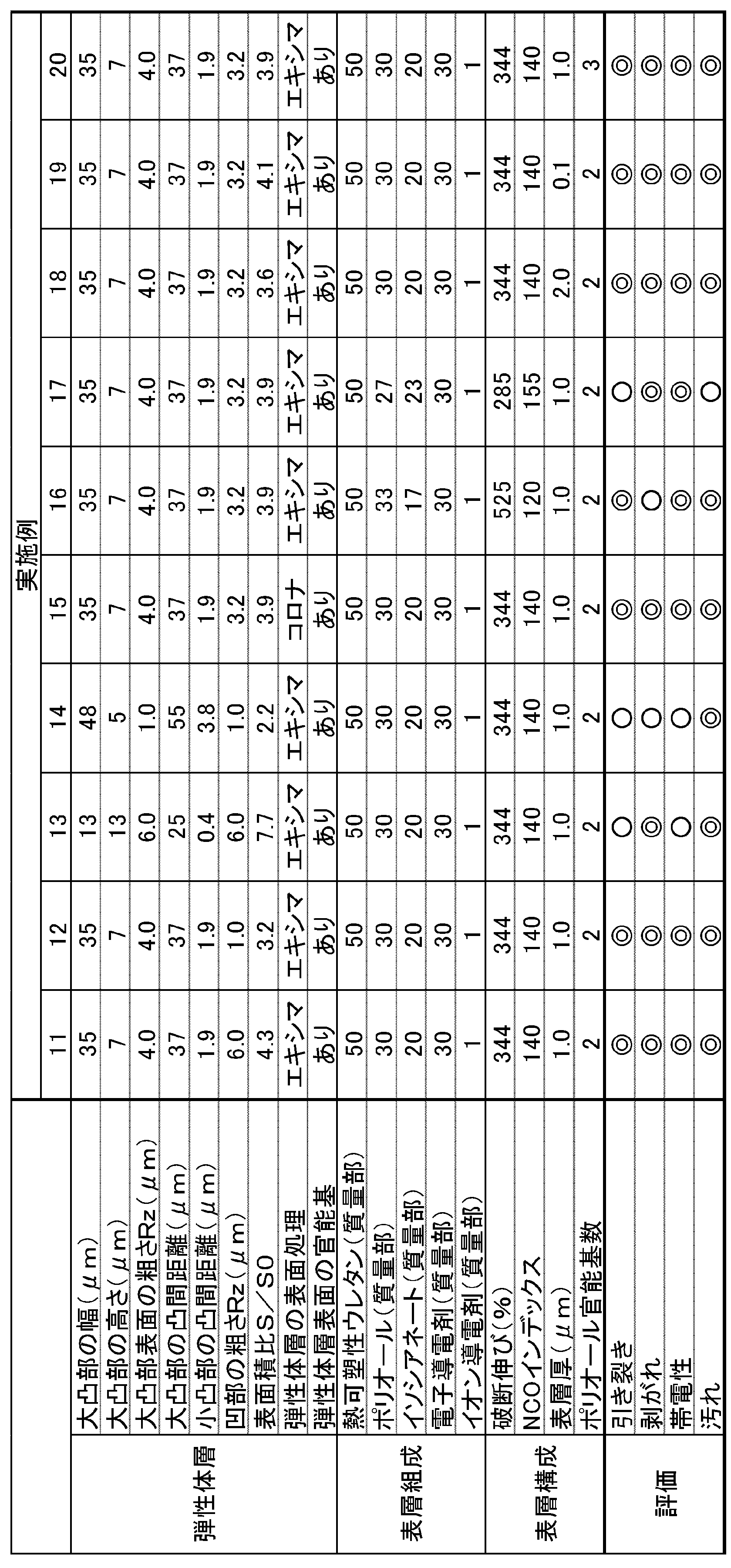

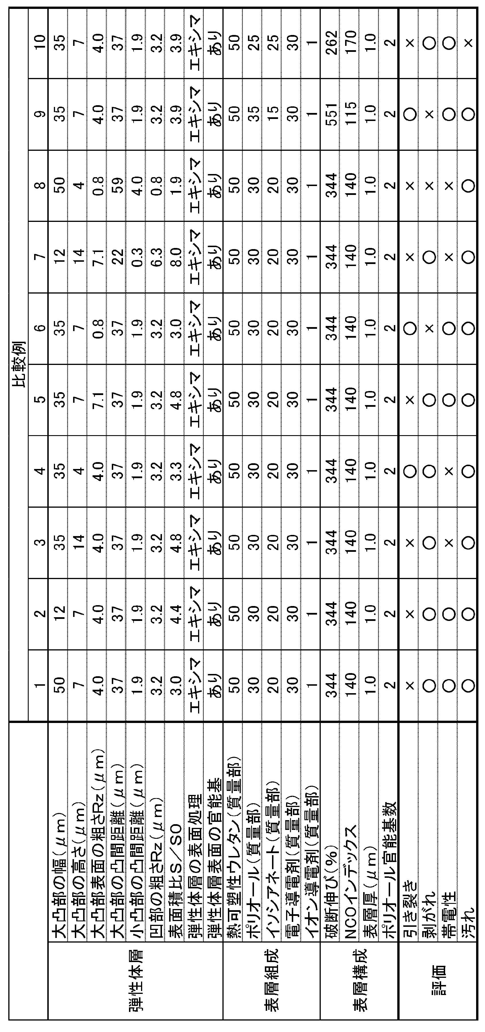
比較例1は、大凸部の幅が大きすぎるため、表層を介して感光体に接する大凸部の接触面積が大きすぎて、大凸部が根元で引き裂かれて破断した。比較例2は、大凸部の幅が小さすぎるため、大凸部による表面凹凸の効果が小さく、表層を介して感光体に接する弾性体層の接触面積が大きすぎて、弾性体層が引き裂かれて破断した。比較例3は、大凸部の高さが高すぎるため、大凸部が根元で引き裂かれて破断した。また、これにより、放電特性が低下し、黒点画像が発生した。比較例4は、大凸部の高さが低すぎるため、粗さが足りず、放電不足により帯電不足となって画像が悪化した。比較例5は、小凸部に起因する大凸部表面の粗さが大きすぎるため、小凸部が根元で引き裂かれて破断した。比較例6は、小凸部に起因する大凸部表面の粗さが小さすぎるため、弾性体層と表層の一体化が低く、耐久時に表層が剥がれた。比較例7は、大凸部の幅が小さすぎるため、大凸部による表面凹凸の効果が小さく、表層を介して感光体に接する弾性体層の接触面積が大きすぎて、弾性体層が引き裂かれて破断した。また、大凸部の高さが高すぎるため、大凸部が根元で引き裂かれて破断した。また、これにより、放電特性が低下し、黒点画像が発生した。また、小凸部に起因する大凸部表面の粗さが大きすぎるため、小凸部が根元で引き裂かれて破断した。比較例8は、大凸部の幅が大きすぎるため、表層を介して感光体に接する大凸部の接触面積が大きすぎて、大凸部が根元で引き裂かれて破断した。また、大凸部の高さが低すぎるため、粗さが足りず、放電不足により帯電不足となって画像が悪化した。また、小凸部に起因する大凸部表面の粗さが小さすぎるため、弾性体層と表層の一体化が低く、耐久時に表層が剥がれた。比較例9は、表層の破断伸びが大きすぎて、感光体との接触部で受ける力によって表層だけが伸び、弾性体層が表層の動きに追従しない。このため、耐久時に表層が剥がれた。一方、比較例10は、表層の破断伸びが小さすぎて、表層が弾性体層の動きに追従しない。このため、耐久時に弾性体層が引き裂かれて破断した。 In Comparative Example 1, since the width of the large protrusion was too large, the contact area of the large protrusion contacting the photoreceptor through the surface layer was too large, and the large protrusion was torn and broken at the base. In Comparative Example 2, since the width of the large protrusions was too small, the effect of surface unevenness due to the large protrusions was small, and the contact area of the elastic layer in contact with the photoreceptor via the surface layer was too large, causing the elastic layer to tear. and broke. In Comparative Example 3, since the height of the large protrusion was too high, the large protrusion was torn and broken at the base. In addition, as a result, discharge characteristics deteriorated, and a black dot image was generated. In Comparative Example 4, since the height of the large convex portion was too low, the roughness was insufficient, and the charging was insufficient due to insufficient discharge, resulting in deterioration of the image. In Comparative Example 5, since the roughness of the surface of the large protrusion due to the small protrusion was too large, the small protrusion was torn at the base and broken. In Comparative Example 6, since the roughness of the surface of the large projections due to the small projections was too small, the integration of the elastic layer and the surface layer was low, and the surface layer peeled off during durability. In Comparative Example 7, since the width of the large protrusions was too small, the effect of surface unevenness due to the large protrusions was small, and the contact area of the elastic layer in contact with the photoreceptor through the surface layer was too large, causing the elastic layer to tear. and broke. Moreover, since the height of the large protrusion was too high, the large protrusion was torn and broken at the base. In addition, as a result, discharge characteristics deteriorated, and a black dot image was generated. Moreover, since the roughness of the surface of the large projection due to the small projection was too large, the small projection was torn and broken at the base. In Comparative Example 8, since the width of the large protrusion was too large, the contact area of the large protrusion contacting the photoreceptor through the surface layer was too large, and the large protrusion was torn and broken at the base. In addition, since the height of the large convex portion was too low, the roughness was insufficient, and the insufficient discharge resulted in insufficient charging, resulting in deterioration of the image. In addition, since the roughness of the surface of the large protrusions due to the small protrusions was too small, the integration between the elastic layer and the surface layer was low, and the surface layer peeled off during durability. In Comparative Example 9, the breaking elongation of the surface layer is too large, and only the surface layer is stretched by the force received at the contact portion with the photoreceptor, and the elastic layer does not follow the movement of the surface layer. Therefore, the surface layer peeled off during durability. On the other hand, in Comparative Example 10, the breaking elongation of the surface layer is too small, and the surface layer does not follow the movement of the elastic layer. Therefore, the elastic layer was torn and broken during durability.
一方、実施例は、弾性体層がシリコーンポリマーを含み、弾性体層の外周表面に幅13μm以上48μm以下で高さ5μm以上13μm以下の複数の大凸部を有するとともに、大凸部の表面に十点平均粗さRzが1.0μm以上6.0μm以下の凹凸を形成する複数の小凸部を有し、表層がウレタンポリマーを含み、表層の破断伸びが285%以上525%以下である。そして、実施例によれば、弾性体層の引き裂き破断、表層の剥がれ、トナー汚れが抑えられている。また、帯電性にも優れる。 On the other hand, in the examples, the elastic layer contains a silicone polymer, and the outer peripheral surface of the elastic layer has a plurality of large protrusions having a width of 13 μm or more and 48 μm or less and a height of 5 μm or more and 13 μm or less. It has a plurality of small projections forming unevenness with a ten-point average roughness Rz of 1.0 μm or more and 6.0 μm or less, a surface layer containing a urethane polymer, and a breaking elongation of the surface layer of 285% or more and 525% or less. Further, according to the examples, the tearing breakage of the elastic layer, the peeling of the surface layer, and the toner contamination are suppressed. In addition, it is excellent in chargeability.
そして、実施例によれば、大凸部の幅および高さ、大凸部表面の粗さRzを調整することで、弾性体層の引き裂き破断をより改善できることがわかる。例えば、大凸部の幅を15μm以上45μm以下、大凸部の高さを12μm以下、大凸部表面の粗さRzを5.5μm以下とすることで、弾性体層の引き裂き破断をより改善できる(実施例1~3、5、7~12)。また、大凸部の高さを調整することで、帯電性をより改善できることがわかる。例えば、大凸部の高さを6μm以上12μm以下とすることで、弾性体層の帯電性をより改善できる(実施例3~4、7~12)。また、大凸部表面の粗さRzを調整することで、表層の剥がれをより改善できることがわかる。例えば、大凸部表面の粗さRzを1.5μm以上とすることで、表層の剥がれをより改善できる(実施例6、7~12)。 Further, according to the examples, it can be seen that by adjusting the width and height of the large protrusions and the roughness Rz of the surface of the large protrusions, the tearing breakage of the elastic layer can be further improved. For example, by setting the width of the large protrusions to 15 μm or more and 45 μm or less, the height of the large protrusions to 12 μm or less, and the roughness Rz of the surface of the large protrusions to 5.5 μm or less, the tear rupture of the elastic layer is further improved. (Examples 1-3, 5, 7-12). Also, it can be seen that the chargeability can be further improved by adjusting the height of the large projections. For example, by setting the height of the large projections to 6 μm or more and 12 μm or less, the chargeability of the elastic layer can be further improved (Examples 3 to 4, 7 to 12). Moreover, it can be seen that peeling of the surface layer can be further improved by adjusting the roughness Rz of the surface of the large protrusions. For example, by setting the roughness Rz of the surface of the large projections to 1.5 μm or more, peeling of the surface layer can be further improved (Examples 6, 7 to 12).
また、実施例7~8と実施例21~22を比較すると、大凸部の凸間距離が25μm以上55μm以下であると、表層の剥がれ、帯電性をより改善できることがわかる。また、実施例9~10と実施例22~24を比較すると、小凸部の凸間距離が0.4μm以上3.8μm以下であると、弾性体層の引き裂き破断、表層の剥がれをより改善できることがわかる。また、実施例11~12と実施例25~26を比較すると、大凸部間の凹部表面の粗さRzが1.0μm以上6.0μm以下であると、表層の剥がれ、帯電性をより改善できることがわかる。また、実施例7~12と実施例27を比較すると、弾性体層に表面処理を施して表面に水酸基またはヒドロペルオキシ基を形成することで、弾性体層の引き裂き破断、表層の剥がれをより改善できることがわかる。また、実施例18~19と実施例28~29を比較すると、表層の厚さが0.1μm以上2.0μm以下であると、弾性体層の引き裂き破断、帯電性、トナー汚れをより改善できることがわかる。また、実施例20と実施例30を比較すると、表層のウレタンポリマーを構成するポリオールの官能基数が3以下であると、トナー汚れをより改善できることがわかる。 Further, when Examples 7-8 and Examples 21-22 are compared, it can be seen that peeling of the surface layer and electrification properties can be further improved when the distance between the large protrusions is 25 μm or more and 55 μm or less. Further, when Examples 9-10 and Examples 22-24 are compared, when the distance between the small protrusions is 0.4 μm or more and 3.8 μm or less, tearing of the elastic layer and peeling of the surface layer are further improved. I know you can. Further, when comparing Examples 11 and 12 with Examples 25 and 26, when the roughness Rz of the surface of the concave portions between the large convex portions is 1.0 μm or more and 6.0 μm or less, the peeling of the surface layer and the chargeability are further improved. I know you can. Further, when comparing Examples 7 to 12 and Example 27, the elastic layer was subjected to surface treatment to form hydroxyl groups or hydroperoxy groups on the surface, thereby further improving the tear fracture of the elastic layer and the peeling of the surface layer. I know you can. Further, comparing Examples 18 and 19 with Examples 28 and 29, it was found that when the thickness of the surface layer was 0.1 μm or more and 2.0 μm or less, the tear breakage of the elastic layer, the electrification property, and the toner contamination could be further improved. I understand. Further, when comparing Example 20 and Example 30, it can be seen that toner contamination can be further improved when the number of functional groups of the polyol constituting the urethane polymer of the surface layer is 3 or less.
以上、本発明の実施形態・実施例について説明したが、本発明は上記実施形態・実施例に何ら限定されるものではなく、本発明の趣旨を逸脱しない範囲内で種々の改変が可能である。 Although the embodiments and examples of the present invention have been described above, the present invention is not limited to the above-described embodiments and examples, and various modifications can be made without departing from the scope of the present invention. .
10 帯電ロール
12 軸体
14 弾性体層
16 表層
18a 大凸部
18b 小凸部
w 大凸部の幅
h 大凸部の高さ
d1 大凸部の凸間距離
d2 小凸部の凸間距離
10 charging
Claims (11)
前記弾性体層が、シリコーンゴムを含み、前記弾性体層の外周表面に、幅13μm以上48μm以下で高さ5μm以上13μm以下の複数の大凸部を有するとともに、前記大凸部の表面に、十点平均粗さRzが1.0μm以上6.0μm以下の凹凸を形成する複数の小凸部を有し、
前記表層が、ウレタンポリマーを含み、前記表層の破断伸びが、285%以上525%以下である、電子写真機器用帯電ロール。 a shaft, an elastic layer formed on the outer peripheral surface of the shaft, and a surface layer formed on the outer peripheral surface of the elastic layer,
The elastic layer contains silicone rubber, and has a plurality of large projections having a width of 13 μm or more and 48 μm or less and a height of 5 μm or more and 13 μm or less on the outer peripheral surface of the elastic layer, and the surfaces of the large projections are: having a plurality of small protrusions forming unevenness with a ten-point average roughness Rz of 1.0 μm or more and 6.0 μm or less,
A charging roll for an electrophotographic device, wherein the surface layer contains a urethane polymer and has an elongation at break of 285% or more and 525% or less.
S:前記弾性体層の実測表面積
S0:前記弾性体層の表面が平坦面であるとしたときの理論表面積 9. The charging roll for electrophotographic equipment according to claim 1, wherein the elastic layer has a surface area ratio S/So of 2.2 or more and 7.7 or less.
S: Measured surface area of the elastic layer S 0 : Theoretical surface area when the surface of the elastic layer is flat
Priority Applications (2)
| Application Number | Priority Date | Filing Date | Title |
|---|---|---|---|
| CN202280013358.0A CN116802566A (en) | 2021-03-25 | 2022-03-13 | Charging rollers for electrophotographic equipment |
| US18/348,336 US12105436B2 (en) | 2021-03-25 | 2023-07-06 | Charging roll for electrophotographic equipment |
Applications Claiming Priority (2)
| Application Number | Priority Date | Filing Date | Title |
|---|---|---|---|
| JP2021-051836 | 2021-03-25 | ||
| JP2021051836A JP2022149607A (en) | 2021-03-25 | 2021-03-25 | Charging roll for electrophotographic apparatuses |
Related Child Applications (1)
| Application Number | Title | Priority Date | Filing Date |
|---|---|---|---|
| US18/348,336 Continuation US12105436B2 (en) | 2021-03-25 | 2023-07-06 | Charging roll for electrophotographic equipment |
Publications (1)
| Publication Number | Publication Date |
|---|---|
| WO2022202425A1 true WO2022202425A1 (en) | 2022-09-29 |
Family
ID=83395132
Family Applications (1)
| Application Number | Title | Priority Date | Filing Date |
|---|---|---|---|
| PCT/JP2022/011153 Ceased WO2022202425A1 (en) | 2021-03-25 | 2022-03-13 | Charging roll for electrophotographic equipment |
Country Status (4)
| Country | Link |
|---|---|
| US (1) | US12105436B2 (en) |
| JP (1) | JP2022149607A (en) |
| CN (1) | CN116802566A (en) |
| WO (1) | WO2022202425A1 (en) |
Citations (5)
| Publication number | Priority date | Publication date | Assignee | Title |
|---|---|---|---|---|
| JP2000075595A (en) * | 1998-08-26 | 2000-03-14 | Fuji Xerox Co Ltd | Electrifying member and electrifying device |
| JP2009162885A (en) * | 2007-12-28 | 2009-07-23 | Canon Chemicals Inc | Electrophotographic roller and method of manufacturing the same |
| JP2014066857A (en) * | 2012-09-26 | 2014-04-17 | Tokai Rubber Ind Ltd | Electrophotographic member |
| JP2015045788A (en) * | 2013-08-29 | 2015-03-12 | 住友理工株式会社 | Charging member |
| JP2019105663A (en) * | 2017-12-08 | 2019-06-27 | 株式会社ブリヂストン | Conductive roller and image forming apparatus |
Family Cites Families (7)
| Publication number | Priority date | Publication date | Assignee | Title |
|---|---|---|---|---|
| JP6140511B2 (en) * | 2013-04-18 | 2017-05-31 | 信越ポリマー株式会社 | Conductive roller and manufacturing method thereof |
| JP6433271B2 (en) * | 2014-12-03 | 2018-12-05 | キヤノン株式会社 | Electrophotographic member and method for producing electrophotographic member |
| US9665049B2 (en) * | 2015-02-26 | 2017-05-30 | Canon Kabushiki Kaisha | Member for electrophotography, method for manufacturing member for electrophotography, and image-forming apparatus |
| US9746792B1 (en) * | 2016-03-22 | 2017-08-29 | Fuji Xerox Co., Ltd. | Charging member, process cartridge, and image forming apparatus for reducing production of micro-chromatic line |
| US10310447B2 (en) * | 2017-07-12 | 2019-06-04 | Canon Kabushiki Kaisha | Electrophotographic member, process cartridge, and electrophotographic image forming apparatus |
| JP7336289B2 (en) * | 2018-07-31 | 2023-08-31 | キヤノン株式会社 | Electrophotographic member, electrophotographic process cartridge and electrophotographic image forming apparatus |
| US20200172701A1 (en) * | 2018-11-29 | 2020-06-04 | Canon Kabushiki Kaisha | Curable silicone rubber mixture, electrophotographic member, and electrophotographic image forming apparatus |
-
2021
- 2021-03-25 JP JP2021051836A patent/JP2022149607A/en active Pending
-
2022
- 2022-03-13 CN CN202280013358.0A patent/CN116802566A/en active Pending
- 2022-03-13 WO PCT/JP2022/011153 patent/WO2022202425A1/en not_active Ceased
-
2023
- 2023-07-06 US US18/348,336 patent/US12105436B2/en active Active
Patent Citations (5)
| Publication number | Priority date | Publication date | Assignee | Title |
|---|---|---|---|---|
| JP2000075595A (en) * | 1998-08-26 | 2000-03-14 | Fuji Xerox Co Ltd | Electrifying member and electrifying device |
| JP2009162885A (en) * | 2007-12-28 | 2009-07-23 | Canon Chemicals Inc | Electrophotographic roller and method of manufacturing the same |
| JP2014066857A (en) * | 2012-09-26 | 2014-04-17 | Tokai Rubber Ind Ltd | Electrophotographic member |
| JP2015045788A (en) * | 2013-08-29 | 2015-03-12 | 住友理工株式会社 | Charging member |
| JP2019105663A (en) * | 2017-12-08 | 2019-06-27 | 株式会社ブリヂストン | Conductive roller and image forming apparatus |
Also Published As
| Publication number | Publication date |
|---|---|
| US20230350321A1 (en) | 2023-11-02 |
| JP2022149607A (en) | 2022-10-07 |
| CN116802566A (en) | 2023-09-22 |
| US12105436B2 (en) | 2024-10-01 |
Similar Documents
| Publication | Publication Date | Title |
|---|---|---|
| US9442408B2 (en) | Member for electrophotography, method for producing the same, and image forming apparatus | |
| EP2169476B1 (en) | Developing roller, developing roller production method, process cartridge, and electrophotographic apparatus | |
| JP5204951B2 (en) | Developing roller and image forming apparatus having the same | |
| JP5219575B2 (en) | Developing roll for electrophotographic equipment | |
| JP6423553B2 (en) | Coating composition for conductive roller, developing roller and image forming apparatus using the same | |
| EP3474078A1 (en) | Conductive roller | |
| JP4732920B2 (en) | Charging roll | |
| JP5386097B2 (en) | Developing roll for electrophotographic equipment | |
| JP3617349B2 (en) | Conductive roll | |
| WO2022202425A1 (en) | Charging roll for electrophotographic equipment | |
| JP6363435B2 (en) | Roller and image forming apparatus using the same | |
| JP5724087B2 (en) | Conductive rubber member and charging roll | |
| EP3190300B1 (en) | Roller and image forming apparatus using same | |
| JP5025983B2 (en) | Developing roller and image forming apparatus having the same | |
| JP5243763B2 (en) | Developing roll | |
| JP4208765B2 (en) | Developing roller, process cartridge, and image forming apparatus | |
| CN112782950A (en) | Developing roller | |
| WO2014136829A1 (en) | Roller, method for manufacturing same and image forming device using same | |
| JP2007039678A (en) | Rubber member | |
| JP4966581B2 (en) | Developing roller and image forming apparatus having the same | |
| JP7270476B2 (en) | COATING COMPOSITION FOR CONDUCTIVE ROLLER, DEVELOPING ROLLER USING THE SAME, AND IMAGE FORMING APPARATUS | |
| JP2006091494A (en) | Contact charging member |
Legal Events
| Date | Code | Title | Description |
|---|---|---|---|
| 121 | Ep: the epo has been informed by wipo that ep was designated in this application |
Ref document number: 22775217 Country of ref document: EP Kind code of ref document: A1 |
|
| WWE | Wipo information: entry into national phase |
Ref document number: 202280013358.0 Country of ref document: CN |
|
| NENP | Non-entry into the national phase |
Ref country code: DE |
|
| 122 | Ep: pct application non-entry in european phase |
Ref document number: 22775217 Country of ref document: EP Kind code of ref document: A1 |