WO2022209793A1 - 車載用アンテナ装置 - Google Patents
車載用アンテナ装置 Download PDFInfo
- Publication number
- WO2022209793A1 WO2022209793A1 PCT/JP2022/011078 JP2022011078W WO2022209793A1 WO 2022209793 A1 WO2022209793 A1 WO 2022209793A1 JP 2022011078 W JP2022011078 W JP 2022011078W WO 2022209793 A1 WO2022209793 A1 WO 2022209793A1
- Authority
- WO
- WIPO (PCT)
- Prior art keywords
- antenna
- vehicle
- frequency band
- antenna device
- patch antenna
- Prior art date
- Legal status (The legal status is an assumption and is not a legal conclusion. Google has not performed a legal analysis and makes no representation as to the accuracy of the status listed.)
- Ceased
Links
Images






Classifications
-
- H—ELECTRICITY
- H01—ELECTRIC ELEMENTS
- H01Q—ANTENNAS, i.e. RADIO AERIALS
- H01Q1/00—Details of, or arrangements associated with, antennas
- H01Q1/27—Adaptation for use in or on movable bodies
- H01Q1/32—Adaptation for use in or on road or rail vehicles
- H01Q1/3208—Adaptation for use in or on road or rail vehicles characterised by the application wherein the antenna is used
-
- H—ELECTRICITY
- H01—ELECTRIC ELEMENTS
- H01Q—ANTENNAS, i.e. RADIO AERIALS
- H01Q1/00—Details of, or arrangements associated with, antennas
- H01Q1/27—Adaptation for use in or on movable bodies
- H01Q1/32—Adaptation for use in or on road or rail vehicles
- H01Q1/325—Adaptation for use in or on road or rail vehicles characterised by the location of the antenna on the vehicle
- H01Q1/3275—Adaptation for use in or on road or rail vehicles characterised by the location of the antenna on the vehicle mounted on a horizontal surface of the vehicle, e.g. on roof, hood, trunk
-
- H—ELECTRICITY
- H01—ELECTRIC ELEMENTS
- H01Q—ANTENNAS, i.e. RADIO AERIALS
- H01Q21/00—Antenna arrays or systems
- H01Q21/28—Combinations of substantially independent non-interacting antenna units or systems
-
- H—ELECTRICITY
- H01—ELECTRIC ELEMENTS
- H01Q—ANTENNAS, i.e. RADIO AERIALS
- H01Q1/00—Details of, or arrangements associated with, antennas
- H01Q1/27—Adaptation for use in or on movable bodies
- H01Q1/32—Adaptation for use in or on road or rail vehicles
- H01Q1/3208—Adaptation for use in or on road or rail vehicles characterised by the application wherein the antenna is used
- H01Q1/3233—Adaptation for use in or on road or rail vehicles characterised by the application wherein the antenna is used particular used as part of a sensor or in a security system, e.g. for automotive radar, navigation systems
-
- H—ELECTRICITY
- H01—ELECTRIC ELEMENTS
- H01Q—ANTENNAS, i.e. RADIO AERIALS
- H01Q1/00—Details of, or arrangements associated with, antennas
- H01Q1/36—Structural form of radiating elements, e.g. cone, spiral, umbrella; Particular materials used therewith
-
- H—ELECTRICITY
- H01—ELECTRIC ELEMENTS
- H01Q—ANTENNAS, i.e. RADIO AERIALS
- H01Q1/00—Details of, or arrangements associated with, antennas
- H01Q1/52—Means for reducing coupling between antennas; Means for reducing coupling between an antenna and another structure
- H01Q1/521—Means for reducing coupling between antennas; Means for reducing coupling between an antenna and another structure reducing the coupling between adjacent antennas
-
- H—ELECTRICITY
- H01—ELECTRIC ELEMENTS
- H01Q—ANTENNAS, i.e. RADIO AERIALS
- H01Q3/00—Arrangements for changing or varying the orientation or the shape of the directional pattern of the waves radiated from an antenna or antenna system
-
- H—ELECTRICITY
- H01—ELECTRIC ELEMENTS
- H01Q—ANTENNAS, i.e. RADIO AERIALS
- H01Q5/00—Arrangements for simultaneous operation of antennas on two or more different wavebands, e.g. dual-band or multi-band arrangements
- H01Q5/10—Resonant antennas
-
- H—ELECTRICITY
- H01—ELECTRIC ELEMENTS
- H01Q—ANTENNAS, i.e. RADIO AERIALS
- H01Q5/00—Arrangements for simultaneous operation of antennas on two or more different wavebands, e.g. dual-band or multi-band arrangements
- H01Q5/30—Arrangements for providing operation on different wavebands
-
- H—ELECTRICITY
- H01—ELECTRIC ELEMENTS
- H01Q—ANTENNAS, i.e. RADIO AERIALS
- H01Q5/00—Arrangements for simultaneous operation of antennas on two or more different wavebands, e.g. dual-band or multi-band arrangements
- H01Q5/30—Arrangements for providing operation on different wavebands
- H01Q5/307—Individual or coupled radiating elements, each element being fed in an unspecified way
-
- H—ELECTRICITY
- H01—ELECTRIC ELEMENTS
- H01Q—ANTENNAS, i.e. RADIO AERIALS
- H01Q5/00—Arrangements for simultaneous operation of antennas on two or more different wavebands, e.g. dual-band or multi-band arrangements
- H01Q5/30—Arrangements for providing operation on different wavebands
- H01Q5/307—Individual or coupled radiating elements, each element being fed in an unspecified way
- H01Q5/314—Individual or coupled radiating elements, each element being fed in an unspecified way using frequency dependent circuits or components, e.g. trap circuits or capacitors
-
- H—ELECTRICITY
- H01—ELECTRIC ELEMENTS
- H01Q—ANTENNAS, i.e. RADIO AERIALS
- H01Q1/00—Details of, or arrangements associated with, antennas
- H01Q1/12—Supports; Mounting means
- H01Q1/22—Supports; Mounting means by structural association with other equipment or articles
- H01Q1/24—Supports; Mounting means by structural association with other equipment or articles with receiving set
- H01Q1/241—Supports; Mounting means by structural association with other equipment or articles with receiving set used in mobile communications, e.g. GSM
-
- H—ELECTRICITY
- H01—ELECTRIC ELEMENTS
- H01Q—ANTENNAS, i.e. RADIO AERIALS
- H01Q9/00—Electrically-short antennas having dimensions not more than twice the operating wavelength and consisting of conductive active radiating elements
- H01Q9/04—Resonant antennas
- H01Q9/0407—Substantially flat resonant element parallel to ground plane, e.g. patch antenna
- H01Q9/0414—Substantially flat resonant element parallel to ground plane, e.g. patch antenna in a stacked or folded configuration
-
- H—ELECTRICITY
- H01—ELECTRIC ELEMENTS
- H01Q—ANTENNAS, i.e. RADIO AERIALS
- H01Q9/00—Electrically-short antennas having dimensions not more than twice the operating wavelength and consisting of conductive active radiating elements
- H01Q9/04—Resonant antennas
- H01Q9/30—Resonant antennas with feed to end of elongated active element, e.g. unipole
- H01Q9/42—Resonant antennas with feed to end of elongated active element, e.g. unipole with folded element, the folded parts being spaced apart a small fraction of the operating wavelength
Definitions
- the present invention relates to an in-vehicle antenna device.
- Patent Document 1 discloses an in-vehicle antenna device in which a planar antenna for GPS signals and an antenna for AM/FM are accommodated in an antenna case.
- One example of the purpose of the present invention is to easily control the directivity of a planar antenna. Other objects of the present invention will become clear from the description herein.
- One aspect of the present invention includes a first antenna that corresponds to radio waves in a first frequency band and a second antenna that corresponds to radio waves in a second frequency band different from the first frequency band, and the second antenna is At least part of the constituent elements is an in-vehicle antenna device that resonates in the first frequency band.
- the directivity of a planar antenna can be easily controlled.
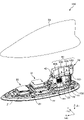
- FIG. 1 is a diagram showing a configuration of an in-vehicle antenna device 10;
- FIG. 3 is an exploded perspective view of the patch antenna 30;
- FIG. It is the perspective view of 60 A of metal bodies, and the side view of 60 A of metal bodies.
- 1 is a diagram showing a configuration of an in-vehicle antenna device 10X;
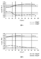
- FIG. 4 is a graph showing an example of the relationship between the elevation angle of the patch antenna 30 and the average gain in the vehicle-mounted antenna device 10 and the vehicle-mounted antenna device 10X.
- 4 is an explanatory diagram of a separation distance D and a separation distance H between the patch antenna 30 and the resonator 61;
- FIG. 3 is an exploded perspective view of the patch antenna 30;
- FIG. It is the perspective view of 60 A of metal bodies, and the side view of 60 A of metal bodies.
- 1 is a diagram showing a configuration of an in-vehicle antenna device 10X;
- FIG. 4 is a graph showing an example of the
- FIG. 7 is a graph showing an example of the relationship between the distance D and the average gain, and the relationship between the distance H and the average gain.
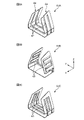
- FIG. 10 is a diagram showing resonance portions 61A to 61C of a modified example; It is a figure which shows the resonance part 61D of a modification, and the resonance part 61E. It is a figure which shows the resonance part 61F of a modification, and the resonance part 61G.
- 11A is a perspective view of the vehicle-mounted antenna device 80A
- FIG. 11B is a side view of the vehicle-mounted antenna device 80A.
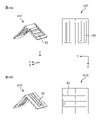
- 12A is a side view of the vehicle antenna device 80B
- FIG. 12B is a side view of the vehicle antenna device 80C.
- FIG. 3 is a diagram showing a configuration of an in-vehicle antenna device 80X; 14A is a graph showing an example of the relationship between the elevation angle and the average gain, and FIG. 14B is a graph showing an elevation angle of 20°.
- FIG. It is a graph which shows an example of the directivity in.
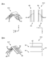
- FIG. 4 is an explanatory diagram of a separation distance D between the patch antenna 30 and the resonator 91; 7 is a graph showing an example of the relationship between the elevation angle and the average gain when the separation distance D is changed; 17A and 17B are side and plan views showing another example of the positional relationship between the patch antenna 30 and the resonating section 61, and FIGS. , and a side view and a plan view showing a second example of the positional relationship.
- FIG. 1 is a diagram showing the configuration of an in-vehicle antenna device 10 according to the first embodiment. Note that FIG. 1 shows a perspective view of the vehicle-mounted antenna device 10 with the case 23 removed in the zenith direction (upward direction). First, an overview of the configuration of the in-vehicle antenna device 10 will be described below with reference to FIG. 1 .
- the front-back direction of the vehicle to which the in-vehicle antenna device 10 is mounted is the X direction
- the left-right direction perpendicular to the X direction is the Y direction
- the vertical direction perpendicular to the X and Y directions is the Z direction.
- the front side from the driver's seat of the vehicle is the +X direction
- the right side is the +Y direction
- the zenith direction (upward direction) is the +Z direction.
- the front-rear, left-right, and up-down directions of the in-vehicle antenna device 10 are the same as the front-rear, left-right, and up-down directions of the vehicle.
- viewing the vehicle-mounted antenna device 10 in the -Z direction is referred to as a "top view”
- viewing the vehicle-mounted antenna device 10 in the +Y direction or the -Y direction is referred to as a "side view”.
- the in-vehicle antenna device 10 is an antenna device attached to the roof of a vehicle (not shown).
- the in-vehicle antenna device 10 has an antenna base 20 , a case 23 , a patch antenna 30 , a patch antenna 31 and an antenna 32 .
- the antenna base 20 is a member forming the bottom surface of the in-vehicle antenna device 10 .
- the antenna base 20 includes, for example, an insulating base made of resin, a metal base 21, and a metal base 22.
- the metal bases 21 and 22 are attached to the insulating base with a plurality of screws (not shown).
- the insulating base may be formed of a material other than resin as long as it is insulating, and may have a shape other than a plate shape.
- the metal base 21 is a member that functions as a ground for the in-vehicle antenna device 10 .
- the metal base 21 is formed in a metal plate shape, for example. However, the metal base 21 may have a shape other than the plate shape as long as it is a metal member that functions as a ground.
- a patch antenna 30 is installed on the metal base 21 .
- the metal base 22 is a member that functions as a ground for the in-vehicle antenna device 10 .
- the metal base 22 is formed in a metal plate shape, for example. However, the metal base 22 may have a shape other than the plate shape as long as it is a metal member that functions as a ground.
- a patch antenna 31 and an antenna 32 are installed on the metal base 22 .
- the metal bases 21 and 22 described above are electrically connected by a metal plate (not shown). Moreover, when the in-vehicle antenna device 10 is attached to the roof of a vehicle (not shown), the metal base 21, the metal base 22, and the roof are electrically connected. As a result, the metal base 21 and the metal base 22 function as a ground for the in-vehicle antenna device 10 .
- the metal base 21 and the metal base 22 are provided separately in this embodiment, they may be provided as an integrated metal base. Even when such an integral metal base is used, the metal base appropriately functions as a ground for patch antennas 31 and antennas 32, which will be described later.
- the antenna base 20 of the vehicle-mounted antenna device 10 is composed of an insulating base, a metal base 21, and a metal base 22 as a member that constitutes the bottom surface of the vehicle-mounted antenna device 10 and a member that functions as a ground. has been described.
- the in-vehicle antenna device 10 is not limited to these configurations.
- the antenna base 20 may have only the metal base 21 and the metal base 22, or may have only an integral metal base instead of the metal base 21 and the metal base 22.
- the antenna base 20 may have an insulating base, a metal base 21 and a metal plate.
- the in-vehicle antenna device 10 may have an insulating base and an integral metal base instead of the metal bases 21 and 22 .
- the in-vehicle antenna device 10 may have an insulating base, metal bases 21 and 22, and another metal base, and a metal plate may be used instead of the metal base.
- the antenna base 20 may have an insulating base and a metal plate.
- the above-described members can be freely combined as the member forming the bottom surface of the vehicle-mounted antenna device 10 and the member functioning as the ground.
- the case 23 is a member (housing) that covers the outside of the in-vehicle antenna device 10 .
- the case 23 is a general shark fin antenna housing, as shown in FIG.
- the patch antenna 30 is, for example, a planar antenna that supports 2.3 GHz band radio waves of satellite digital radio broadcasting service (SDARS: Satellite Digital Audio Radio Service).
- SDARS Satellite Digital Audio Radio Service
- the patch antenna 30 receives radio waves in the 2.3 GHz band for SDARS.
- the communication standard and frequency band with which the patch antenna 30 is compatible are not limited to those described above, and other communication standards and frequency bands may be used.
- the patch antenna 30 may be compatible with radio waves in a plurality of frequency bands, and may transmit or receive radio waves in a desired frequency band.
- the patch antenna 30 may be referred to as "first antenna”. Also, the frequency band of radio waves to which the patch antenna 30 corresponds may be referred to as a "first frequency band”.
- the patch antenna 31 is, for example, a planar antenna that supports radio waves in the 1.5 GHz band of the Global Navigation Satellite System (GNSS). In this embodiment, the patch antenna 31 receives radio waves in the 1.5 GHz band for GNSS.
- the communication standard and frequency band with which the patch antenna 31 is compatible are not limited to those described above, and other communication standards and frequency bands may be used. Also, the patch antenna 31 may be compatible with radio waves in a plurality of frequency bands, and may transmit or receive radio waves in a desired frequency band.
- the antenna 32 is, for example, an antenna corresponding to radio waves for AM/FM radio.
- the antenna 32 receives AM broadcast radio waves of 522 kHz to 1710 kHz and FM broadcast radio waves of 76 MHz to 108 MHz.
- the antenna 32 may receive only one of the radio waves for AM broadcasting and the radio waves for FM broadcasting.
- the communication standard and frequency band with which the antenna 32 is compatible are not limited to those described above, and other communication standards and frequency bands may be used. Further, the antenna 32 may at least either transmit or receive radio waves in a desired frequency band.
- the antenna 32 may be referred to as a "second antenna”.
- the frequency band of radio waves to which the antenna 32 corresponds may be referred to as a "second frequency band”.
- FIG. 2 is an exploded perspective view of the patch antenna 30.
- FIG. Details of the patch antenna 30 will be described below with reference to FIG. 2 together with FIG. 1 described above.
- the patch antenna 30 has a substrate 70 , a dielectric member 72 , a radiating element 73 , a holding member 74 and a metal body 75 .
- the board 70 is a circuit board on which the dielectric member 72 is installed. As shown in FIG. 2, substrate 70 is attached to metal base 21 .
- the dielectric member 72 is a substantially rectangular plate-like member made of a dielectric material such as ceramic. As shown in FIG. 2, the front and back surfaces of the dielectric member 72 are parallel to the X and Y directions, the front surface of the dielectric member 72 is oriented in the +Z direction, The back surface of the dielectric member 72 is oriented in the -Z direction. A pattern 71 is provided on the back surface of the dielectric member 72 .
- the pattern 71 is a conductor that functions as a ground conductor film (or ground conductor plate).
- the back surface of dielectric member 72 is attached to substrate 70, for example, by an adhesive (not shown).
- substantially quadrilateral refers to a shape consisting of four sides, including squares and rectangles, for example.
- a notch (concave portion) or protrusion (convex portion) may be provided on a part of the sides.
- the shape of the dielectric member 72 is not limited to a substantially quadrilateral shape, and may be circular or elliptical, for example.
- the dielectric member 72 may have a shape other than a plate shape.
- the radiating element 73 is a conductive substantially quadrangular member having an area smaller than the front surface area of the dielectric member 72 . As shown in FIG. 2, the radiating element 73 is provided on the front surface of the dielectric member 72 . Also, the normal direction of the radiation surface of the radiation element 73 is the +Z direction.
- the shape of the radiating element 73 is not limited to a substantially rectangular shape, and may be circular or elliptical, for example. In other words, the radiation element 73 may have a shape that enables at least one of reception and transmission of signals (radio waves) in a desired frequency band.
- the radiating element 73 has a feeding point 78 as shown in FIG.
- Feed point 78 is the point at which feed line 77 shown in FIG. 2 is electrically connected to radiating element 73 .
- only one feeding line 77 is connected to the radiating element 73, that is, a single feeding system is adopted.
- the radiation element 73 of the one-feed system has, for example, a substantially rectangular shape with different lengths and widths so that at least one of transmission and reception of a desired circularly polarized wave is possible.
- the “substantially rectangular” is a shape included in the above-described “substantially quadrilateral”.
- a configuration in which two feeder lines 77 are provided to be connected to the radiating element 73 that is, a two-feed system may be employed.
- the two-feed system radiation element 73 has, for example, a substantially square shape with equal lengths and widths so that desired circularly polarized waves can be transmitted and received.
- the “substantially square” is a shape included in the above-described “substantially quadrilateral”.
- a through hole 76 that penetrates the substrate 70 and the dielectric member 72 is formed.
- the through hole 76 is formed so that the feed line 77 is connected at the feed point 78 of the radiating element 73 .
- two through-holes 76 are formed through the substrate 70 and the dielectric member 72 in the two-feed system radiation element 73 .
- a feed line 77 is connected at a feed point 78 of the radiating element 73 .
- the holding member 74 is a member that holds the metal body 75 .
- the holding member 74 is made of resin and provided on the front surface of the dielectric member 72 so as to surround the radiating element 73 .
- the holding member 74 may be made of a material other than resin as long as it can hold the metal body 75 .
- the side on the +X side has a convex portion 74A extending in the +Z direction
- the side on the -X side has a convex portion 74B and a convex portion extending in the +Z direction.
- a portion 74C is provided.
- Each of the protrusions 74A to 74C is a substantially rectangular parallelepiped protrusion formed to determine the position of the metal body 75 with respect to the holding member 74. As shown in FIG. However, each of the projections 74A to 74C need not be provided as a substantially rectangular parallelepiped projection as long as the position of the metal body 75 with respect to the holding member 74 can be determined. Further, the holding member 74 may not be provided with the projections 74A to 74C. Moreover, the holding member 74 is not limited to a frame shape surrounding the entire circumference of the radiation element 73 .
- the case 23 may have a structure that also serves as the holding member 74 .
- the metal body 75 is a member that improves the radiation efficiency of the patch antenna 30 and controls the directivity by being capacitively coupled with the radiation element 73 .
- the metal body 75 is a substantially square zenith plate (or zenith capacitance plate) held by the holding member 74. Of the two sides parallel to the Y axis, the +X side has a concave portion 75A, and the -X side has a concave portion 75A. A recessed portion 75B and a recessed portion 75C are provided on the side edge.
- the metal body 75 is placed on the front surface of the holding member 74 with the projections 74A to 74C of the holding member 74 fitted in the recesses 75A to 75C of the metal body 75, respectively. placed. However, if the holding member 74 is not provided with the protrusions 74A to 74C, the metal body 75 may not be provided with the recesses 75A to 75C.
- the metal body 75 has a substantially square plate shape, it is not limited to this, and may be a substantially quadrilateral shape other than a substantially square shape, or may be circular or elliptical. Furthermore, the metal body 75 may have a three-dimensional shape obtained by bending a plate-like metal plate. The metal body 75 may be formed in an inverted V shape, an inverted U shape, a mountain shape (umbrella shape), or an arch shape, for example, by bending a metal plate. Moreover, the metal body 75 may have a shape other than a plate shape.
- FIG. 3A is a perspective view of a metal body 60A of a capacitive loading element 60, which will be described later.
- FIG. 3B is a side view of a metal body 60A of a capacitive loading element 60, which will be described later. Details of the antenna 32 will be described below with reference to FIGS. 3A and 3B together with FIG. 1 described above.
- the antenna 32 has a holder 40, a helical element 50, a capacitive loading element 60, and a filter 100.
- the holder 40 is a member that holds the helical element 50 and the capacitive loading element 60 .
- the holder 40 is provided on the antenna base 20 as shown in FIG. Further, the holder 40 is made of resin, for example. However, the holder 40 may be made of a material other than resin as long as it can hold the helical element 50 and the capacitive loading element 60 .
- the holder 40 has a support section 41 and a mounting section 42, as shown in FIG.
- the strut portion 41 is a portion to which the helical element 50 is attached.
- the attachment portion 42 is a portion to which the capacitive loading element 60 is attached.
- the mounting portion 42 has a substantially trapezoidal cross-section whose longitudinal direction is the X direction and whose left and right widths widen toward the lower side ( ⁇ Z direction).
- the shape of the attachment portion 42 is not limited to the shape having the substantially trapezoidal cross section described above.
- the cross-sectional shape of the mounting portion 42 when viewed from the front or rear may be a substantially square shape such as a substantially square or substantially rectangular shape
- the external shape of the mounting portion 42 when viewed from the front or rear may be:
- An inverted V shape, an inverted U shape, a mountain shape (umbrella shape), or an arch shape may be used.
- the helical element 50 is an element that resonates in a desired frequency band together with the capacitive loading element 60. As shown in FIG. 1, the coil 50 is provided above the metal base 22 while being attached to the pillar portion 41 of the holder 40 . One end of the coil 50 is electrically connected to the metal base 22 and the other end of the coil 50 is electrically connected to the capacitive loading element 60 .
- the capacitive loading element 60 is an element that resonates together with the coil 50 in a desired frequency band. As shown in FIG. 1, the capacitive loading element 60 is composed of metal bodies 60A to 60D divided into four along the front-rear direction (longitudinal direction).
- metal body refers to an object formed by processing a metal member. Including metal parts.
- each of the metal bodies 60A to 60D of the present embodiment has both ends in the Y-axis direction of the metal plate as bottom surfaces substantially parallel to the central XY plane. It is formed by bending upward from both ends.
- the bottom portion of each of the metal bodies 60A to 60D which is substantially parallel to the center XY plane, may be simply referred to as the "bottom portion".
- the left side may be simply referred to as the "left side portion” and the right side may simply be referred to as the "right side portion”.
- FIGS. 3A and 3B show only the metal body 60A among the metal bodies 60A to 60D
- the metal bodies 60B to 60D shown in FIG. It has a section, a left side section and a right side section.
- the four metal bodies 60A to 60D have the same length in the front-rear direction, but are not limited to this.
- the four metal bodies 60A to 60D may have different lengths in the front-rear direction, or may have the same length.
- each of the metal bodies 60A to 60D has a shape having a bottom portion, but may include a metal body that does not have a bottom portion.
- the capacitive loading element 60 has four metal bodies 60A to 60D, but is not limited to this.
- the capacitive loading element 60 may have one metal body, or may have a plurality of metal bodies other than four.
- the capacitive loading element 60 has a shape that is bent upward from both ends of the central bottom surface, but the shape is not limited to this.
- the capacitive loading element 60 may be bent downward from both ends.
- the external shape of the capacitive loading element 60 when viewed from the front or rear may be, for example, an inverted V shape, an inverted U shape, a mountain shape (umbrella shape), or an arch shape.
- the filter 100 is a member that electrically connects the four metal bodies 60A to 60D and has a high impedance in the radio wave frequency band corresponding to the patch antennas 30 and 31 .
- This embodiment has three filters 100 .
- Each of the three filters 100 has, as shown in FIG. provided in the gap between the metal body 60C and the metal body 60D.
- the filter 100 is, for example, a parallel-resonant circuit in the frequency band of radio waves corresponding to the patch antennas 30 and 31, and includes a capacitor and a coil (not shown).
- the filter 100 may be arranged at a position connecting adjacent metal bodies among the metal bodies 60A to 60D. Therefore, the filter 100 may be provided, for example, at an upper position including the top of the metal bodies 60A to 60D, or at a lower position including the bottom. Also, the filter 100 may be arranged only on the right side surface of the capacitive loading element 60 . Furthermore, the filters 100 may be alternately arranged on the left side and right side of the capacitive loading element 60 .
- the four metal bodies 60A to 60D are electrically connected via the filter 100 that has high impedance in the radio wave frequency band to which the patch antennas 30 and 31 correspond.
- the coil 50 is designed to have a high impedance in the radio wave frequency band to which the patch antennas 30 and 31 correspond.
- the filter 100 Since the filter 100 has a low impedance in the AM/FM frequency band, all of the metal bodies 60A-60D operate as a single conductor with the coil 50 for the AM/FM frequency band. That is, the coil 50 and the capacitive loading element 60 operate as an antenna that resonates in the FM frequency band.
- a member provided to resonate in a desired frequency band in the in-vehicle antenna device 10 may be called an "element" or an "element".
- the vehicle-mounted antenna device 10 of this embodiment described above is a so-called compound antenna device having the patch antenna 30, the patch antenna 31 and the antenna 32.
- FIG. In such a composite antenna device, it is necessary to secure necessary characteristics for each antenna while considering electrical interference between the antennas.
- an element for example, a dielectric member 72, radiating element 73, etc.
- the vehicle-mounted antenna device 10 capable of easily controlling the directivity of the patch antenna 30 will be described below.
- the capacitive loading element 60 including the metal body 60A resonates together with the coil 50 in the FM frequency band (second frequency band).
- the capacitive loading element 60 is provided with a resonant portion 61 as shown in FIGS. 1 and 3A and 3B.
- the resonance part 61 is a part that resonates in a radio wave frequency band (first frequency band) to which the patch antenna 30 (first antenna) corresponds.
- the entire metal body 60A functions as the resonance section 61 . Therefore, the metal body 60A is a part of the element of the antenna 32 (second antenna) corresponding to radio waves in the AM/FM frequency band (second frequency band), and has the resonating portion 61, thereby forming a patch antenna.
- 30 (first antenna) resonates in the frequency band (first frequency band) of corresponding radio waves.
- the electrical length of the resonance section 61 is formed so that the patch antenna 30 (first antenna) resonates in the corresponding radio wave frequency band (first frequency band).
- the resonator 61 is formed with an electrical length corresponding to half the wavelength of the first frequency band.
- “half the wavelength of the first frequency band” is not limited to an exact value, and may be a value that resonates in a desired frequency band. This is because the wavelength of the first frequency band is not necessarily represented by a divisible integer, and the actual electrical length of the resonator 61 varies due to various factors. It should be noted that the electrical length of the resonant portion 61 does not have to correspond to half the wavelength of the first frequency band as long as it is formed to resonate in the first frequency band.
- slits 62 are provided in the metal body 60A.
- the slit 62 is a notch (gap) formed inward from the outer edge of the metal body 60A.
- three slits 62 are arranged in the Z direction on the left side of the metal body 60A.
- the three slits 62 are composed of a slit 62 formed in the -X direction, a slit 62 formed in the +X direction, and a slit 62 formed in the -X direction when viewed in order in the +Z direction.
- the resonant portion 61 is formed by repeatedly folding back 64 in the horizontal direction (that is, in a meandering shape) in the metal body 60A.
- the electrical length that resonates in the first frequency band is adjusted by adjusting the horizontal length of the slit 62. can be formed.
- the number, positions, extending directions, etc. of the slits 62 are not limited to those shown in FIGS. 3A and 3B.
- one slit 62 may be provided in the metal body 60A.
- one fold 64 is provided on the metal body 60A.
- a plurality of slits 62 other than three may be provided in the metal body 60A. In this case, folds 64 corresponding to the number of slits 62 are provided.
- the slit 62 is provided only on the left side surface of the metal body 60A, but the slit 62 may also be provided on the bottom surface of the metal body 60A, for example.
- the direction in which the slit 62 extends is not limited to the horizontal direction, and may be the vertical direction.
- the “horizontal direction” or “vertical direction” is not limited to a strict direction, and includes directions that deviate within a predetermined angle. This is because each part (bottom part, left side part, or right side part) of the metal body 60A is not necessarily provided parallel to the "horizontal direction” or the "vertical direction”. Also.
- the slit 62 is provided so as to extend along the horizontal direction, but the slit 62 may be bent from the middle.
- the electrical length of the resonant portion 61 of the present embodiment is formed so that the patch antenna 30 (first antenna) resonates in the corresponding radio frequency band (first frequency band), the slit
- the number, position, extending direction, etc. of 62 can be freely combined.
- the slit 62 is also provided on the right side of the metal body 60A in the same manner as the slit 62 is provided on the left side of the metal body 60A.
- the number, position, extending direction, etc. of the slits 62 are the same on the left side of the metal body 60A and on the right side of the metal body 60A, as shown in FIG. 3A. However, the number, position, extending direction, etc. of the slits 62 may differ between the left side surface of the metal body 60A and the right side surface of the metal body 60A.
- the metal body 60A has the resonance portion 61
- At least one of the metal bodies 60A to 60D forming the capacitive loading element 60 should have the resonance portion 61.
- FIG. That is, for example, only the metal body 60B may have the resonance section 61, or both the metal bodies 60C and 60D may have the resonance section 61.
- the capacitive loading element 60 is one metal body, one metal body may have the resonance section 61 . Therefore, at least part of the elements forming the antenna 32 (second antenna) should resonate in the radio wave frequency band (first frequency band) to which the patch antenna 30 (first antenna) corresponds.
- FIG. 4 is a diagram showing the configuration of a vehicle-mounted antenna device 10X of a comparative example.
- the vehicle-mounted antenna device 10X is a vehicle-mounted antenna device in which the capacitive loading element 60 of the antenna 32 is not provided with the resonance section 61 .
- the vehicle-mounted antenna device 10X has the same configuration as the vehicle-mounted antenna device 10 of the present embodiment described above, except that the resonance unit 61 is not provided.
- FIG. 5 is a graph showing an example of the relationship between the elevation angle of the patch antenna 30 and the average gain in the vehicle-mounted antenna device 10 and the vehicle-mounted antenna device 10X.
- the horizontal axis indicates the elevation angle
- the vertical axis indicates the average gain.
- the dashed line indicates the calculation result in the vehicle-mounted antenna device 10X
- the solid line indicates the calculation result in the vehicle-mounted antenna device 10.
- the ⁇ mark on the broken line and the ⁇ mark on the solid line indicate the position of the numerical value on the vertical axis with respect to the numerical value on the horizontal axis. Note that in the following description, the average gain may be simply referred to as "gain".
- the gain of the in-vehicle antenna device 10X of the comparative example is in the range of 20° to 65°.
- the gain in the vehicle antenna device 10 is higher than the gain in the vehicle antenna device 10X of the comparative example. Therefore, the in-vehicle antenna device 10 of the present embodiment, for example, as an antenna device for receiving radio waves transmitted from a satellite, has an improved average gain in at least part of the elevation angle range from the low elevation angle to the middle elevation angle of the patch antenna 30. and has ideal directivity.
- the angle of elevation is 0° in the horizontal direction and 90° in the zenith.
- the low elevation angle means, for example, a range of 0° to 30°.
- the medium elevation angle means a range of 30° to 60°.
- the high elevation angle means a range of 60° to 90°.
- the vehicle-mounted antenna device 10 of the present embodiment can easily control the directivity of the patch antenna 30 by having the resonance section 61 .
- the in-vehicle antenna device 10 of the present embodiment can easily control the directivity of the patch antenna 31 other than the patch antenna 30 by having the separate resonance section 61 . . That is, the in-vehicle antenna device 10 of the present embodiment can easily control the directivity of planar antennas such as the patch antenna 30 and the patch antenna 31 .
- the patch antenna 30 and the resonator 61 do not overlap each other.
- the phase of the radio wave corresponding to the patch antenna 30 and the phase of the radio wave corresponding to the antenna 32 provided with the resonating section 61 The phase reinforces each other.
- the gain of the patch antenna 30 is further improved when the phases of the radio waves have a separation distance that strengthens each other. Therefore, in the following, the separation distance at which the phase of the radio wave corresponding to the patch antenna 30 and the phase of the radio wave corresponding to the antenna 32 strengthen each other will be verified.
- FIG. 6 is an explanatory diagram of the separation distance D and the separation distance H.
- a separation distance D is a separation distance in the horizontal direction (X direction) between the patch antenna 30 and the resonance section 61 of the antenna 32 in a side view as shown in FIG. Specifically, the separation distance D is the distance in the horizontal direction between the end of the patch antenna 30 closest to the resonating section 61 and the end of the resonating section 61 closest to the patch antenna 30 .
- the separation distance H is the separation distance in the vertical direction (Z direction) between the patch antenna 30 and the resonance section 61 of the antenna 32 in a side view as shown in FIG. Specifically, the separation distance H is the distance between the end of the patch antenna 30 closest to the resonating section 61 and the end of the resonating section 61 closest to the patch antenna 30 in the vertical direction.
- FIG. 7A is a graph showing an example of the relationship between the separation distance D and the average gain.
- FIG. 7B is a graph showing an example of the relationship between the separation distance H and the average gain.
- the horizontal axis indicates the separation distance D
- the vertical axis indicates the average gain of the patch antenna 30.
- the horizontal axis indicates the separation distance H
- the vertical axis indicates the average gain of the patch antenna 30 .
- the dashed-dotted line indicates the calculation result for the patch antenna 30 at an elevation angle of 20°
- the solid line indicates the calculation result for the patch antenna 30 at an elevation angle of 50°.
- the average gain becomes equal to or greater than the reference value (line A), and the required gain of the patch antenna 30 can be obtained. Also, when the separation distance D is 30 mm or more and the elevation angle is 20°, the average gain is equal to or greater than the reference value (line B).
- the average gain becomes equal to or more than the reference value (line A), and the required gain of the patch antenna 30 can be obtained.
- the separation distance D is 30 mm or more and the elevation angle is 20°
- the average gain is equal to or greater than the reference value (line B).
- the required gain of the patch antenna 30 can be obtained by separating the patch antenna 30 and the resonating section 61 by 30 mm or more in the horizontal or vertical direction.
- 30 mm corresponds to a quarter of the wavelength of the radio wave frequency band (first frequency band) to which the patch antenna 30 (first antenna) corresponds. Therefore, in the in-vehicle antenna device 10 of the present embodiment, the first antenna (patch antenna 30) and the resonating section 61 are separated in the horizontal direction or the vertical direction by at least 1/4 of the wavelength of the first frequency band. is desirable.
- a quarter of the wavelength of the first frequency band is not limited to an exact value, and may be any value that provides the necessary gain of the patch antenna 30. This is because the wavelength of the first frequency band is not necessarily represented by a divisible integer, and the actual electrical length of the resonator 61 varies due to various factors. In addition, since the desired separation distance between the patch antenna 30 and the resonating section 61 also changes depending on the reference value (A line, B line) of the required average gain of the patch antenna 30, the first antenna (patch antenna 30) The portion 61 does not have to be spaced horizontally or vertically by more than a quarter of the wavelength of the first frequency band.
- FIGS. 8A to 8C are diagrams showing the resonators 61A to 61C of the modification.
- the above-described resonance portion 61 is formed by repeatedly folding back 64 in the horizontal direction in the metal body 60A.
- the resonating portion 61 is not limited to this shape.
- a slit 62 substantially parallel to the YZ plane may be provided across the left side, the bottom, and the right side of the metal body 60A, as in the resonance section 61A shown in FIG. 8A.
- the metal body 60A is provided with two slits 62 aligned in the X direction, as shown in FIG. 8A.
- the two slits 62 are the slit 62 formed in the direction from the left side to the bottom side to the right side, and the slit 62 formed in the direction from the right side to the bottom side to the left side when viewed in order from the -X direction. It is composed of a slit 62 that is
- the metal body 60A is provided with two folds 64 as shown in FIG. 8A.
- Two folds 64 are provided on the left side and the right side.
- the resonance portion 61A is formed by repeatedly folding back 64 in the vertical direction in the metal body 60A.
- the length of the slit 62 is adjusted to form an electrical length that resonates in the first frequency band (for example, an electrical length corresponding to half the wavelength of the first frequency band). can be done.
- the slits 62 are formed in the resonance section 61 and the resonance section 61A described above. However, in order to form the resonance section with an electrical length that resonates in the first frequency band, it is not limited to forming the slit 62 .
- Slots 63 may be formed as in resonating portions 61B and 61C shown in FIGS. 8B and 8C. The slot 63 is an opening (hole or gap) formed in the metal body 60A.
- the resonance section 61B is provided with slots 63 that are repeatedly folded in the horizontal direction on the left and right side surfaces of the metal body 60A.
- the slots 63 on the left side and the slots 63 on the right side are connected on the bottom side of the metal body 60A.
- the resonance section 61C has a slot 63 extending over the left side, the bottom and the right side of the metal body 60A, and the slot 63 is repeatedly folded back in the vertical direction.
- FIGS. 9A and 9B are diagrams showing a resonating portion 61D and a resonating portion 61E of modified examples.
- 10A and 10B are diagrams showing a resonating portion 61F and a resonating portion 61G of modifications.
- the resonance section 61 and the resonance sections 61A to 61C described above are provided on a metal body 60A having a shape that is bent upward from both ends of the central bottom surface.
- the resonators may be provided on a mountain-shaped (umbrella-shaped) metal body.
- the mountain-shaped (umbrella-shaped) metal body is formed by connecting the upper edges of the left side and the right side, and the outer shape of the metal body when viewed from the front or rear is an inverted V shape. Including configurations that are inverted U-shaped, arcuate, and generally trapezoidal.
- a resonance part 61D shown in FIG. 9A is formed in a mountain-shaped (umbrella-shaped) metal body, and is formed by repeatedly folding back 64 in the horizontal direction with slits 62 .
- a resonance part 61E shown in FIG. 9B is formed in a mountain-shaped (umbrella-shaped) metal body, and is formed by repeatedly folding back 64 in the vertical direction with slits 62 .
- the resonance part 61F shown in FIG. 10A is formed in a mountain-shaped (umbrella-shaped) metal body, and is formed with a slot 63 that repeats folding in the horizontal direction.
- a resonance part 61G shown in FIG. 10B is formed in a mountain-shaped (umbrella-shaped) metal body, and is formed with a slot 63 that repeats folding in the vertical direction.
- the length of the slit 62 or the slot 63 is adjusted to adjust the length of the slit 62 or the slot 63 so that the electrical length that resonates in the first frequency band (for example, electrical length corresponding to one-half of the wavelength).
- the in-vehicle antenna device 10 which is a compound antenna device having the patch antenna 30 as the first antenna and the AM/FM radio antenna 32 as the second antenna, has been described.
- the capacitive loading element 60 of the antenna 32 resonates with the coil 50 in the FM frequency band (second frequency band), and furthermore, the radio wave frequency band (second frequency band) to which the patch antenna 30 (first antenna) corresponds. 1 frequency band).
- the second antenna is not limited to an antenna for AM/FM radio, and may be an antenna compatible with other communication standards and frequency bands.
- the second antenna may be an antenna for telematics, as in vehicle-mounted antenna devices 80A to 80C, which will be described later.
- FIG. 11 is a diagram showing the configuration of an in-vehicle antenna device 80A.
- 11A is a perspective view of the vehicle-mounted antenna device 80A
- FIG. 11B is a side view of the vehicle-mounted antenna device 80A.
- the in-vehicle antenna device 80A has an antenna base 20, a patch antenna 30, and an antenna 33A.
- illustration of a member (housing) covering the outside of the vehicle-mounted antenna device 80A, that is, a member corresponding to the case 23 in the vehicle-mounted antenna device 10 of the first embodiment shown in FIG. 1 is omitted. is doing.
- the antenna base 20 of the present embodiment is the same as the antenna base 20 of the in-vehicle antenna device 10 of the first embodiment, so detailed description thereof will be omitted.
- the patch antenna 30 of the present embodiment is also the same as the patch antenna 30 of the in-vehicle antenna device 10 of the first embodiment, detailed description thereof will be omitted.
- 11A and 11B illustration of members corresponding to the holding member 74 and the metal body 75 in the patch antenna 30 shown in FIG. 2 is omitted.
- Antenna 33A is an antenna for telematics.
- Antenna 33A for example, radio waves in the 700 MHz to 2.7 GHz band used for LTE (Long Term Evolution), Sub-6 band used for 5G (5th generation mobile communication system), that is, from the 3.6 GHz band
- This antenna is compatible with radio waves in frequency bands of less than 6 GHz.
- the communication standard and frequency band with which the antenna 33A is compatible are not limited to those described above, and other communication standards and frequency bands may be used.
- the antenna 33A is, for example, V2X (Vehicle to Everything: vehicle-to-vehicle communication, road-to-vehicle communication), Wi-Fi (registered trademark), Bluetooth (registered trademark), and an antenna that corresponds to radio waves in the frequency band used for DAB.
- the antenna 33A may be an antenna for keyless entry or an antenna for smart entry.
- the antenna 33A may be an antenna that supports communication by MIMO (Multiple-Input Multiple-Output).
- the vehicle-mounted antenna device 80A further has an antenna similar to the antenna 33A, so that the vehicle-mounted antenna device 80A supports communication by MIMO.
- the vehicle-mounted antenna device 80A that performs MIMO communication transmits data from each of the plurality of antennas constituting the vehicle-mounted antenna device 80A, and simultaneously receives data from the plurality of antennas.
- the in-vehicle antenna device 80A of this embodiment is a composite antenna device having the patch antenna 30 and the antenna 33A. Also in such a vehicle-mounted antenna device 80A, similarly to the vehicle-mounted antenna device 10 of the first embodiment, the directivity of the patch antenna 30 can be easily controlled by having a resonance section 91, which will be described later.
- the antenna 33A of the vehicle-mounted antenna device 80A may be referred to as a "second antenna” in the following description.
- the frequency band of radio waves to which the antenna 33A corresponds may be referred to as a "second frequency band”.
- the antenna 33A (second antenna) has an element 90A that resonates in the radio wave frequency band (second frequency band) to which the antenna 33A corresponds.
- the element 90A is provided with a resonance section 91 as shown in FIGS. 11A and 11B.
- the resonance part 91 is a part that resonates in a radio wave frequency band (first frequency band) to which the patch antenna 30 (first antenna) corresponds.
- part of the meander-shaped element 90A functions as a resonance section 91, as indicated by broken lines in FIGS. 11A and 11B.
- the resonator 91 is a part of the element 90A of the antenna 33A (second antenna) that corresponds to radio waves in the telematics frequency band (second frequency band), and the patch antenna 30 (first antenna) corresponds to it. It resonates in the frequency band (first frequency band) of the radio wave.
- the electrical length of the resonance section 91 is formed so that the patch antenna 30 (first antenna) resonates in the corresponding radio wave frequency band (first frequency band).
- the resonator 91 is formed with an electrical length corresponding to a quarter of the wavelength of the first frequency band.
- a quarter of the wavelength of the first frequency band is not limited to an exact value, and may be a value that resonates in a desired frequency band. This is because the wavelength of the first frequency band is not necessarily represented by a divisible integer, and the actual electrical length of the resonator 91 varies due to various factors. It should be noted that the electrical length of the resonant portion 91 does not have to correspond to a quarter of the wavelength of the first frequency band as long as it is formed to resonate in the first frequency band.
- slits 92 are provided in the element 90A.
- the slit 92 is a notch (gap) formed inward from the outer edge of the element 90A.
- Element 90A is provided with two slits 92 as shown in FIG. 11B.
- the two slits 92 are formed in the -Z direction from the upper end of the element 90A in the side view shown in FIG. It is configured.
- the element 90A is provided with two folds 93 as shown in FIG. 11B.
- the two folds 93 are provided on the +X direction side of the element 90A and the -X direction side of the element 90A when viewed in order in the +Z direction.
- the resonating portion 91 is formed by repeating horizontal folds 93 in the element 90A (that is, in a meandering shape).
- the electrical length that resonates in the first frequency band is adjusted by adjusting the horizontal length of the slit 92. can be formed.
- the number, positions, extending directions, etc. of the slits 92 are not limited to those shown in FIG. 11B.
- one slit 92 may be provided in the element 90A.
- the slit 92 is provided with one fold 93 .
- the element 90A may be provided with slits 92 other than two. In this case, folds 93 corresponding to the number of slits 92 are provided.
- the direction in which the slits 92 extend is not limited to the horizontal direction, and may be the vertical direction. Also. In FIG. 11B, one slit 92 is bent from the middle, but it may be provided so as to extend only along the horizontal direction. Further, the resonance portion 91 may be formed by repeatedly folding the element 90A in the vertical direction. Furthermore, slots may be formed in the element 90A instead of slits.
- the electrical length of the resonant portion 91 of the present embodiment is formed so that the patch antenna 30 (first antenna) resonates in the corresponding radio wave frequency band (first frequency band), the slit
- the number, position, extending direction, etc. of 92 or slots can be freely combined.
- the element 90A does not have to be partially meander-shaped.
- the width of the antenna element is formed to have a predetermined length that resonates in the first frequency band.
- FIG. 12 is a diagram showing the configuration of the in-vehicle antenna device 80B and the in-vehicle antenna device 80C.
- 12A is a side view of the vehicle-mounted antenna device 80B
- FIG. 12B is a side view of the vehicle-mounted antenna device 80C.
- the in-vehicle antenna device 80B has an antenna base 20, a patch antenna 30, and an antenna 33B which is an antenna for telematics.
- the configuration of the vehicle-mounted antenna device 80B is the same as the configuration of the vehicle-mounted antenna device 80A, except that the shape of the antenna 33B is different from the shape of the antenna 33A in the above-described vehicle-mounted antenna device 80A. Therefore, only the details of the antenna 33B will be described below.
- the antenna 33B of the in-vehicle antenna device 80B may be referred to as "second antenna”.
- the frequency band of the radio waves that the antenna 33B corresponds to may be referred to as a "second frequency band”.
- the antenna 33B (second antenna) has an element 90B that resonates in the radio wave frequency band (second frequency band) to which the antenna 33B corresponds.
- the width W1 of the element 90B is an electrical length corresponding to a quarter of the wavelength of the radio wave frequency band (first frequency band) to which the patch antenna 30 (first antenna) corresponds. formed.
- part of the element 90B functions as a resonance section 91 that resonates in the first frequency band. Therefore, the resonance unit 91 is a part of the element 90B of the antenna 33B (second antenna) that corresponds to radio waves in the telematics frequency band (second frequency band), and the patch antenna 30 (first antenna) corresponds to it. It resonates in the frequency band (first frequency band) of the radio wave.
- the element 90B of the antenna 33B which is an antenna for telematics, is not limited to the shape shown in FIG. 12A, and may have another shape as shown in FIG. 12B.
- the in-vehicle antenna device 80C has an antenna base 20, a patch antenna 30, and an antenna 33C which is an antenna for telematics.
- the configuration of the vehicle-mounted antenna device 80C is the same as the configuration of the vehicle-mounted antenna device 80B, except that the shape of the antenna 33C differs from the shape of the antenna 33B in the above-described vehicle-mounted antenna device 80B. Therefore, only the details of the antenna 33C will be described below.
- the antenna 33C of the in-vehicle antenna device 80C may be referred to as a "second antenna”.
- the frequency band of radio waves to which the antenna 33C corresponds may be referred to as a "second frequency band”.
- the antenna 33C has an element 90C that resonates in the radio wave frequency band (second frequency band) to which the antenna 33C (second antenna) corresponds.
- the element 90C of the antenna 33C is obliquely formed at the upper end as compared with the element 90B of the antenna 33B shown in FIG. 12A.
- the width W2 of the element 90C is an electrical length corresponding to a quarter of the wavelength of the radio wave frequency band (first frequency band) to which the patch antenna 30 (first antenna) corresponds. formed.
- part of the element 90C functions as a resonance section 91 that resonates in the first frequency band. Therefore, the resonator 91 is a part of the element 90C of the antenna 33C (second antenna) that corresponds to radio waves in the frequency band for telematics (second frequency band), and the patch antenna 30 (first antenna) corresponds to it. It resonates in the frequency band (first frequency band) of the radio wave.
- characteristics of the patch antenna 30 in the vehicle-mounted antenna device 80X and characteristics of the patch antenna 30 in the vehicle-mounted antenna device 80C of the third example of the present embodiment are compared using a vehicle-mounted antenna device 80X of a comparative example to be described later. explain the comparison of
- FIG. 13 is a diagram showing the configuration of a vehicle-mounted antenna device 80X of a comparative example.
- the vehicle-mounted antenna device 80X is a vehicle-mounted antenna device having only the patch antenna 30, as shown in FIG. Therefore, in the following description, the vehicle-mounted antenna device 80X may be referred to as a "patch antenna single model".
- the vehicle-mounted antenna device 80X is a vehicle-mounted antenna device obtained by removing the antenna 33C from the above-described vehicle-mounted antenna device 80C.
- the vehicle-mounted antenna device 80X has the same configuration as the vehicle-mounted antenna device 80C of the third example of the present embodiment described above, except that the antenna 33C is not provided.
- FIG. 14 is a graph showing the characteristics of the patch antenna 30 in the vehicle-mounted antenna device 80C and the vehicle-mounted antenna device 80X. Note that FIG. 14A is a graph showing an example of the relationship between elevation angle and average gain, and FIG. 14B is a graph showing an example of directivity at an elevation angle of 20°.
- the horizontal axis indicates the elevation angle
- the vertical axis indicates the average gain.
- the dashed line indicates the calculation result in the vehicle-mounted antenna device 80X
- the solid line indicates the calculation result in the vehicle-mounted antenna device 80C.
- the ⁇ marks on the dashed line and the ⁇ marks on the solid line indicate the positions of the numerical values on the vertical axis with respect to the numerical values on the horizontal axis. Note that in the following description, the average gain may be simply referred to as "gain".
- the in-vehicle antenna device 80C of the present embodiment for example, as an antenna device for receiving radio waves transmitted from a satellite, has an improved average gain in at least a partial elevation angle range from a low elevation angle to a medium elevation angle of the patch antenna 30. and has ideal directivity.
- the vehicle-mounted antenna device 80 ⁇ /b>C of the present embodiment can easily control the directivity of the patch antenna 30 by having the resonance section 91 .
- the above-described vehicle-mounted antenna device 80A and vehicle-mounted antenna device 80B also have the resonance section 91, so that the directivity of the patch antenna 30 can be easily controlled.
- the patch antenna 30 and the resonance section 91 in the in-vehicle antenna devices 80A to 80C of this embodiment do not overlap each other. Also, although not shown, the patch antenna 30 and the resonance section 91 in the in-vehicle antenna devices 80A to 80C of the present embodiment do not overlap each other even when viewed from above.
- the patch antenna 30 and the resonator 91 are spaced apart by a predetermined distance in the horizontal direction or the vertical direction. ing. At this time, the phase of the radio wave corresponding to the patch antenna 30 and the phase of the radio wave corresponding to the antennas 33A to 33C provided with the resonance section 91 reinforce each other. Therefore, in the following, the separation distance between the phase of the radio wave corresponding to the patch antenna 30 and the phase of the radio wave corresponding to the antenna 33C among the antennas 33A to 33C is verified.
- FIG. 15 is an explanatory diagram of the separation distance D between the patch antenna 30 and the resonance section 91.
- a separation distance D is a separation distance in the horizontal direction (X direction) between the patch antenna 30 and the resonance section 91 of the antenna 33C in a side view as shown in FIG. Specifically, the separation distance D is the distance in the horizontal direction between the end of the patch antenna 30 closest to the resonant section 91 and the end of the resonant section 91 closest to the patch antenna 30 .
- FIG. 16 is a graph showing an example of the relationship between the elevation angle and the average gain when the separation distance D is changed.
- the horizontal axis indicates the elevation angle
- the vertical axis indicates the average gain.
- the dashed line indicates the calculation result of the vehicle-mounted antenna device 80X of the comparative example
- the calculation results of the vehicle-mounted antenna device 80C of the present embodiment when the separation distance D is changed are indicated by a plurality of solid lines.
- there is Calculation results when the separation distance D is changed to 8 mm, 16 mm, 32 mm, 64 mm, 128 mm, and 256 mm are shown using ⁇ marks and ⁇ marks on the solid line.
- ⁇ and ⁇ marks on these solid lines indicate the positions of the numerical values on the vertical axis with respect to the numerical values on the horizontal axis, and are indicated by ⁇ and ⁇ for convenience of distinction. Note that in the following description, the average gain may be simply referred to as "gain".
- the gain of the vehicle-mounted antenna device 80C is higher than the gain of the vehicle-mounted antenna device 80X (single patch antenna model, circle mark), especially in the range of low elevation angles. getting low.
- the gain of the vehicle antenna device 80C is the gain of the vehicle antenna device 80X (single patch antenna model, ⁇ mark). is higher than
- the characteristics of the patch antenna 30 of the vehicle-mounted antenna device 80C are better than those of the single patch antenna model.
- 16 mm corresponds to one eighth of the wavelength of the radio wave frequency band (first frequency band) to which the patch antenna 30 (first antenna) corresponds. Therefore, in the vehicle-mounted antenna device 80C of the present embodiment, it is desirable that the first antenna (patch antenna 30) and the resonator 91 are separated in the horizontal direction by at least one-eighth of the wavelength of the first frequency band.
- the gain of the vehicle-mounted antenna device 80C is slightly higher than the gain of the vehicle-mounted antenna device 80X (single patch antenna model, circle mark).
- the graph for the vehicle-mounted antenna device 80C and the graph for the vehicle-mounted antenna device 80X substantially match. That is, when the separation distance D is 256 mm, the gain of the vehicle-mounted antenna device 80C is almost the same as the gain of the vehicle-mounted antenna device 80X (single patch antenna model).
- the separation distance D is greater than 128 mm
- the characteristics of the patch antenna 30 of the in-vehicle antenna device 80C are almost the same as those of the single patch antenna model.
- 128 mm corresponds to one wavelength in the radio wave frequency band (first frequency band) to which the patch antenna 30 (first antenna) corresponds. Therefore, in the in-vehicle antenna device 80C of the present embodiment, the horizontal separation distance between the first antenna (patch antenna 30) and the resonating section 91 is one wavelength or less in the first frequency band. This is particularly advantageous because it improves the properties of
- FIG. 17 is a diagram showing another example of the positional relationship between the patch antenna 30 and the resonator 61. As shown in FIG. 17A and 17B are a side view and a plan view showing a first example of the positional relationship, and FIGS. 17C and 17D are a side view and a plan view showing a second example of the positional relationship.
- the patch antenna 30 and the resonance section 61 do not overlap each other in top view and side view.
- the patch antenna 30 and the resonance section 61 overlap each other in the side view shown in FIG. 17A.
- the patch antenna 30 and the resonator 61 do not overlap each other.
- the dashed line shown in FIG. 17A is an auxiliary line for indicating that the patch antenna 30 and the resonance section 61 overlap each other.
- the patch antenna 30 and the resonating section 61 do not overlap each other, while in the top view shown in FIG. 61 overlap each other.
- the dashed line shown in FIG. 17C is an auxiliary line for indicating that the patch antenna 30 and the resonance section 61 overlap each other.
- the directivity of the patch antenna 30 can be more easily controlled even when the patch antenna 30 and the resonating section 61 do not overlap each other in one of the top view and side view, such as the first and second examples of the positional relationship. can do.
- the in-vehicle antenna device 10 includes a patch antenna 30 (first antenna) that corresponds to radio waves in the 2.3 GHz band (first frequency band) for SDARS, and a first frequency band.
- An antenna 32 (second antenna) that supports radio waves in a different band, for example, a 522 kHz to 1710 kHz band for AM broadcasting and a 76 MHz to 108 MHz band (second frequency band) for FM broadcasting.
- At least a portion (eg, the metal body 60A) of the element (eg, capacitive loading element 60) that constitutes the second antenna resonates in the first frequency band.
- the in-vehicle antenna device 10 of this embodiment it is possible to easily control the directivity of the planar antenna (for example, the patch antenna 30).
- the in-vehicle antenna devices 80A to 80C of this embodiment have been described.
- the in-vehicle antenna devices 80A to 80C include, for example, a patch antenna 30 (first antenna) that supports radio waves in the 2.3 GHz band (first frequency band) for SDARS. and antennas 33A to 33C (second antennas) that correspond to radio waves in, for example, a telematics frequency band (second frequency band) different from the first frequency band.
- At least some of the elements (for example, the elements 90A to 90C) forming the second antenna resonate in the first frequency band.
- the directivity of the planar antenna for example, the patch antenna 30
- the directivity of the planar antenna can be easily controlled.
- At least part of the element (eg, capacitive loading element 60) (eg, metal body 60A) resonates in the first frequency band, as shown in FIGS. It has a resonance part 61 formed with an electrical length. This makes it possible to easily control the directivity of the planar antenna (for example, the patch antenna 30).
- the electrical length of the resonator 61 is half the wavelength of the first frequency band. This makes it possible to easily control the directivity of the planar antenna (for example, the patch antenna 30).
- the resonance section 61 has at least one fold 64 as shown in FIGS. 3, 8, 9 and 10, for example. Thereby, an electrical length that resonates in the first frequency band can be formed in the resonance section 61 .
- the resonance section 61 has a gap (slit 62 or slot 63) extending in at least one of the horizontal direction and the vertical direction. Thereby, an electrical length that resonates in the first frequency band can be formed in the resonance section 61 .
- the resonance section 61 is formed by repeating horizontal folds, as shown in FIGS. 3, 8B, 9A and 10A, for example. Thereby, an electrical length that resonates in the first frequency band can be formed in the resonance section 61 .
- the patch antenna 30 (first antenna) and the resonance section 61 do not overlap each other in top view and side view. This makes it possible to more easily control the directivity of the planar antenna (for example, the patch antenna 30).
- the patch antenna 30 (first antenna) and the resonance section 61 do not overlap each other in top view or side view. This makes it possible to more easily control the directivity of the planar antenna (for example, the patch antenna 30).
- the patch antenna 30 (first antenna) and the resonator 61 are separated by a predetermined distance in the horizontal or vertical direction, as shown in FIGS. 1 and 6, for example. This makes it possible to more easily control the directivity of the planar antenna (for example, the patch antenna 30).
- the predetermined distance is a quarter or more of the wavelength of the first frequency band. This makes it possible to more easily control the directivity of the planar antenna (for example, the patch antenna 30).
- the second frequency band is lower than the first frequency band. This makes it possible to easily control the directivity of the planar antenna (for example, the patch antenna 30).
- “In-vehicle” in this embodiment means that it can be mounted on a vehicle, so it is not limited to those attached to the vehicle, but also includes those that are brought into the vehicle and used inside the vehicle.
- the antenna device of the present embodiment is used in a "vehicle” which is a vehicle with wheels, it is not limited to this, and can be used for flying objects such as drones, probes, and construction machines without wheels. , agricultural machinery, ships, and other moving bodies.
Landscapes
- Engineering & Computer Science (AREA)
- Remote Sensing (AREA)
- Computer Security & Cryptography (AREA)
- Radar, Positioning & Navigation (AREA)
- Waveguide Aerials (AREA)
- Details Of Aerials (AREA)
- Variable-Direction Aerials And Aerial Arrays (AREA)
Abstract
Description
<構成の概要>
図1は、第1実施形態である車載用アンテナ装置10の構成を示す図である。なお、図1は、ケース23を天頂方向(上方向)に取り外した車載用アンテナ装置10の斜視図を示している。以下では、まず、図1を参照しつつ、車載用アンテナ装置10の構成の概要を説明する。
図2は、パッチアンテナ30の分解斜視図である。以下では、上述した図1とともに、図2を参照しつつ、パッチアンテナ30の詳細を説明する。
図3Aは、後述する容量装荷素子60の金属体60Aの斜視図である。図3Bは、後述する容量装荷素子60の金属体60Aの側面図である。以下では、上述した図1とともに、図3A及び図3Bを参照しつつ、アンテナ32の詳細を説明する。
ところで、上述した本実施形態の車載用アンテナ装置10は、パッチアンテナ30,パッチアンテナ31及びアンテナ32を有する、いわゆる複合アンテナ装置である。このような複合アンテナ装置では、アンテナ同士の電気的干渉を考慮しつつ、個々のアンテナにおいて必要な特性を確保する必要がある。上述した本実施形態の車載用アンテナ装置10は、例えば、パッチアンテナ30において、他のアンテナとの電気的干渉を考慮しつつ、必要な指向性を確保するために、エレメント(例えば、誘電体部材72や放射素子73など)の大きさや位置を調整することが可能である。
図4は、比較例の車載用アンテナ装置10Xの構成を示す図である。車載用アンテナ装置10Xは、アンテナ32の容量装荷素子60において共振部61が設けられていない車載用アンテナ装置である。なお、車載用アンテナ装置10Xは、共振部61が設けられていないこと以外は、上述した本実施形態の車載用アンテナ装置10と同様の構成を備える。
以下では、車載用アンテナ装置10及び車載用アンテナ装置10Xにおける、パッチアンテナ30の仰角と平均利得とを計算した結果を説明する。
ここで、図1に示される上面視及び側面視において、パッチアンテナ30と、共振部61とは、互いに非重複である。そして、パッチアンテナ30と共振部61とが、水平方向又は鉛直方向において所定距離離間しているとき、パッチアンテナ30が対応する電波の位相と、共振部61が設けられるアンテナ32が対応する電波の位相とが強め合う。本実施形態の車載用アンテナ装置10では、この電波の位相が強め合う離間距離を有するとき、パッチアンテナ30の利得がより改善する。そこで、以下では、パッチアンテナ30が対応する電波の位相と、アンテナ32が対応する電波の位相とが強め合う離間距離を検証する。
図8A~図8Cは、変形例の共振部61A~共振部61Cを示す図である。
<第1例の車載用アンテナ装置80A>
図11は、車載用アンテナ装置80Aの構成を示す図である。なお、図11Aは、車載用アンテナ装置80Aの斜視図であり、図11Bは、車載用アンテナ装置80Aの側面図である。
車載用アンテナ装置80Bは、アンテナベース20と、パッチアンテナ30と、テレマティクス用のアンテナであるアンテナ33Bとを有する。車載用アンテナ装置80Bの構成は、アンテナ33Bの形状が、上述した車載用アンテナ装置80Aにおけるアンテナ33Aの形状と異なる以外は、車載用アンテナ装置80Aの構成と同様である。このため、以下では、アンテナ33Bの詳細についてのみ説明する。
車載用アンテナ装置80Cは、アンテナベース20と、パッチアンテナ30と、テレマティクス用のアンテナであるアンテナ33Cとを有する。車載用アンテナ装置80Cの構成は、アンテナ33Cの形状が、上述した車載用アンテナ装置80Bにおけるアンテナ33Bの形状と異なる以外は、車載用アンテナ装置80Bの構成と同様である。このため、以下では、アンテナ33Cの詳細についてのみ説明する。
図13は、比較例の車載用アンテナ装置80Xの構成を示す図である。車載用アンテナ装置80Xは、図13に示されるように、パッチアンテナ30のみを有する車載用アンテナ装置である。そこで、以下の説明では、車載用アンテナ装置80Xを、「パッチアンテナ単体モデル」と称することがある。
以下では、車載用アンテナ装置80C及び車載用アンテナ装置80Xにおける、パッチアンテナ30の特性を計算した結果を説明する。
図17は、パッチアンテナ30と共振部61との位置関係の別の例を示す図である。なお、図17A及び図17Bは、位置関係の第1例を示す側面図及び平面図であり、図17C及び図17Dは、位置関係の第2例を示す側面図及び平面図である。
以上、本実施形態の車載用アンテナ装置10について説明した。車載用アンテナ装置10は、例えば、図1に示されるように、例えば、SDARS用の2.3GHz帯(第1周波数帯)の電波に対応するパッチアンテナ30(第1アンテナ)と、第1周波数帯と異なる、例えば、AM放送用の522kHz~1710kHz帯及びFM放送用の76MHz~108MHz帯(第2周波数帯)の電波に対応するアンテナ32(第2アンテナ)と、を備える。そして、第2アンテナを構成するエレメント(例えば、容量装荷素子60)の少なくとも一部(例えば、金属体60A)は、第1周波数帯で共振する。本実施形態の車載用アンテナ装置10によれば、平面アンテナ(例えば、パッチアンテナ30)の指向性を容易に制御することができる。
20 アンテナベース
21,22 金属ベース
23 ケース
30 パッチアンテナ(第1アンテナ)
31 パッチアンテナ
32 アンテナ(第2アンテナ)
33A~33C アンテナ(第2アンテナ)
40 ホルダ
41 支柱部
42 取付部
50 ヘリカル素子(コイル)
60 容量装荷素子
60A~60D 金属体
61 共振部
62 スリット
63 スロット
64 折返し
70 基板
71 パターン
72 誘電体部材
73 放射素子
74 保持部材
74A~74C 凸部
75 金属体
75A~75C 凹部
76 貫通孔
77 給電線
78 給電点
90A~90C エレメント
91 共振部
92 スリット
93 折返し
100 フィルタ
Claims (11)
- 第1周波数帯の電波に対応する第1アンテナと、
前記第1周波数帯と異なる第2周波数帯の電波に対応する第2アンテナと、を備え、
前記第2アンテナを構成するエレメントの少なくとも一部は、前記第1周波数帯で共振する、
車載用アンテナ装置。 - 前記エレメントの前記少なくとも一部は、前記第1周波数帯で共振する電気長で形成される共振部を有する、
請求項1に記載の車載用アンテナ装置。 - 前記共振部の電気長は、前記第1周波数帯の波長の2分の1である、
請求項2に記載の車載用アンテナ装置。 - 前記共振部は、少なくとも一つの折返しを有する、
請求項2又は3に記載の車載用アンテナ装置。 - 前記共振部は、水平方向及び鉛直方向の少なくとも一方に延びる隙間が形成されている、
請求項2から4のいずれか一項に記載の車載用アンテナ装置。 - 前記共振部は、水平方向の折返しを繰り返して形成される、
請求項5に記載の車載用アンテナ装置。 - 上面視及び側面視において、
前記第1アンテナと、前記共振部とは、互いに非重複である、
請求項2から6のいずれか一項に記載の車載用アンテナ装置。 - 上面視又は側面視において、
前記第1アンテナと、前記共振部とは、互いに非重複である、
請求項2から6のいずれか一項に記載の車載用アンテナ装置。 - 前記第1アンテナと前記共振部とは、水平方向又は鉛直方向において、所定距離離間している、
請求項2から8のいずれか一項に記載の車載用アンテナ装置。 - 前記所定距離は、前記第1周波数帯の波長の4分の1以上である、
請求項9に記載の車載用アンテナ装置。 - 前記第2周波数帯は、前記第1周波数帯よりも低い、
請求項1から10のいずれか一項に記載の車載用アンテナ装置。
Priority Applications (7)
| Application Number | Priority Date | Filing Date | Title |
|---|---|---|---|
| JP2023510854A JP7653509B2 (ja) | 2021-03-29 | 2022-03-11 | 車載用アンテナ装置 |
| EP22780014.1A EP4318802A4 (en) | 2021-03-29 | 2022-03-11 | ON-BOARD ANTENNA DEVICE |
| CN202280025485.2A CN117083769A (zh) | 2021-03-29 | 2022-03-11 | 车载用天线装置 |
| CN202511104056.6A CN120657419A (zh) | 2021-03-29 | 2022-03-11 | 复合天线装置 |
| US18/284,533 US20250087874A1 (en) | 2021-03-29 | 2022-03-11 | Vehicular antenna device |
| JP2024006663A JP7618855B2 (ja) | 2021-03-29 | 2024-01-19 | 車載用アンテナ装置 |
| JP2025041104A JP2025085734A (ja) | 2021-03-29 | 2025-03-14 | 車載用アンテナ装置 |
Applications Claiming Priority (2)
| Application Number | Priority Date | Filing Date | Title |
|---|---|---|---|
| JP2021-054757 | 2021-03-29 | ||
| JP2021054757 | 2021-03-29 |
Publications (1)
| Publication Number | Publication Date |
|---|---|
| WO2022209793A1 true WO2022209793A1 (ja) | 2022-10-06 |
Family
ID=83456217
Family Applications (1)
| Application Number | Title | Priority Date | Filing Date |
|---|---|---|---|
| PCT/JP2022/011078 Ceased WO2022209793A1 (ja) | 2021-03-29 | 2022-03-11 | 車載用アンテナ装置 |
Country Status (5)
| Country | Link |
|---|---|
| US (1) | US20250087874A1 (ja) |
| EP (1) | EP4318802A4 (ja) |
| JP (3) | JP7653509B2 (ja) |
| CN (2) | CN120657419A (ja) |
| WO (1) | WO2022209793A1 (ja) |
Families Citing this family (2)
| Publication number | Priority date | Publication date | Assignee | Title |
|---|---|---|---|---|
| US12554948B2 (en) * | 2020-02-11 | 2026-02-17 | Avid Identification Systems, Inc. | Method for validating radio frequency identification number |
| TWI916980B (zh) | 2024-09-23 | 2026-03-01 | 全波科技股份有限公司 | 無人載具天線抑制敵方干擾及增進我方信號強度的系統架構 |
Citations (4)
| Publication number | Priority date | Publication date | Assignee | Title |
|---|---|---|---|---|
| JP2009296281A (ja) * | 2008-06-04 | 2009-12-17 | Fujitsu Ten Ltd | マルチバンドアンテナ |
| WO2010004671A1 (ja) * | 2008-07-11 | 2010-01-14 | 日本アンテナ株式会社 | アンテナ装置 |
| WO2017141635A1 (ja) * | 2016-02-19 | 2017-08-24 | 株式会社ヨコオ | アンテナ装置 |
| WO2018159668A1 (ja) * | 2017-02-28 | 2018-09-07 | 株式会社ヨコオ | アンテナ装置 |
Family Cites Families (13)
| Publication number | Priority date | Publication date | Assignee | Title |
|---|---|---|---|---|
| JP2002151925A (ja) * | 2000-11-06 | 2002-05-24 | Central Glass Co Ltd | 車両用のガラスアンテナ |
| DE10304911B4 (de) * | 2003-02-06 | 2014-10-09 | Heinz Lindenmeier | Kombinationsantennenanordnung für mehrere Funkdienste für Fahrzeuge |
| US8098205B2 (en) * | 2009-05-05 | 2012-01-17 | Flextronics Automotive Inc. | GPS, GSM, and wireless LAN antenna for vehicle applications |
| JP4952835B2 (ja) * | 2009-11-20 | 2012-06-13 | 株式会社デンソー | 変形折返しダイポールアンテナ及びそのインピーダンス調整方法、アンテナ装置 |
| JP2012054915A (ja) * | 2010-08-06 | 2012-03-15 | Nippon Soken Inc | アンテナ構造及びダイバーシティアンテナ構造 |
| JP4913900B1 (ja) * | 2010-12-08 | 2012-04-11 | 日本アンテナ株式会社 | アンテナ装置 |
| JP5592989B2 (ja) * | 2013-10-18 | 2014-09-17 | 原田工業株式会社 | アンテナ装置 |
| EP3133695B1 (en) * | 2015-08-18 | 2021-04-07 | TE Connectivity Nederland B.V. | Antenna system and antenna module with reduced interference between radiating patterns |
| KR101709077B1 (ko) * | 2015-11-20 | 2017-02-22 | 현대자동차주식회사 | 안테나 장치, 그의 제조 방법 및 그를 가지는 차량 |
| JP6792406B2 (ja) * | 2016-10-21 | 2020-11-25 | 株式会社ヨコオ | 車載用アンテナ装置 |
| DE212017000251U1 (de) * | 2016-11-24 | 2019-06-28 | Yokowo Co., Ltd. | Antennenbefestigungselement und Antennenvorrichtung |
| EP3534458A4 (en) * | 2016-12-06 | 2020-07-01 | Yokowo Co., Ltd | ANTENNA DEVICE |
| CN113839223B (zh) * | 2017-02-23 | 2024-02-27 | 株式会社友华 | 天线装置 |
-
2022
- 2022-03-11 WO PCT/JP2022/011078 patent/WO2022209793A1/ja not_active Ceased
- 2022-03-11 CN CN202511104056.6A patent/CN120657419A/zh active Pending
- 2022-03-11 EP EP22780014.1A patent/EP4318802A4/en active Pending
- 2022-03-11 US US18/284,533 patent/US20250087874A1/en active Pending
- 2022-03-11 JP JP2023510854A patent/JP7653509B2/ja active Active
- 2022-03-11 CN CN202280025485.2A patent/CN117083769A/zh active Pending
-
2024
- 2024-01-19 JP JP2024006663A patent/JP7618855B2/ja active Active
-
2025
- 2025-03-14 JP JP2025041104A patent/JP2025085734A/ja active Pending
Patent Citations (5)
| Publication number | Priority date | Publication date | Assignee | Title |
|---|---|---|---|---|
| JP2009296281A (ja) * | 2008-06-04 | 2009-12-17 | Fujitsu Ten Ltd | マルチバンドアンテナ |
| WO2010004671A1 (ja) * | 2008-07-11 | 2010-01-14 | 日本アンテナ株式会社 | アンテナ装置 |
| JP2010021856A (ja) | 2008-07-11 | 2010-01-28 | Nippon Antenna Co Ltd | アンテナ装置 |
| WO2017141635A1 (ja) * | 2016-02-19 | 2017-08-24 | 株式会社ヨコオ | アンテナ装置 |
| WO2018159668A1 (ja) * | 2017-02-28 | 2018-09-07 | 株式会社ヨコオ | アンテナ装置 |
Non-Patent Citations (1)
| Title |
|---|
| See also references of EP4318802A4 |
Also Published As
| Publication number | Publication date |
|---|---|
| EP4318802A4 (en) | 2025-03-19 |
| CN120657419A (zh) | 2025-09-16 |
| US20250087874A1 (en) | 2025-03-13 |
| JPWO2022209793A1 (ja) | 2022-10-06 |
| CN117083769A (zh) | 2023-11-17 |
| JP7653509B2 (ja) | 2025-03-28 |
| EP4318802A1 (en) | 2024-02-07 |
| JP2025085734A (ja) | 2025-06-05 |
| JP7618855B2 (ja) | 2025-01-21 |
| JP2024027192A (ja) | 2024-02-29 |
Similar Documents
| Publication | Publication Date | Title |
|---|---|---|
| US20240283143A1 (en) | Antenna device | |
| US11936101B2 (en) | Antenna device | |
| US11177578B2 (en) | Antenna device for vehicle | |
| JP6792406B2 (ja) | 車載用アンテナ装置 | |
| JP2025085734A (ja) | 車載用アンテナ装置 | |
| US11152693B2 (en) | Antenna device | |
| CN113690579A (zh) | 天线装置 | |
| US20250087900A1 (en) | Antenna device | |
| CN110574230B (zh) | 车载用天线装置 | |
| US12316030B1 (en) | Low-profile composite antenna device | |
| JP4163059B2 (ja) | 多周波共用アンテナ | |
| JP5053009B2 (ja) | 車載用テレビアンテナ及びその取付方法 | |
| CN117178430A (zh) | 车载用天线装置 | |
| WO2022102771A1 (ja) | アンテナ | |
| US20240283142A1 (en) | Vehicular antenna device | |
| JP4532370B2 (ja) | 多周波一体型アンテナ | |
| JP2011019038A (ja) | 平面アンテナ |
Legal Events
| Date | Code | Title | Description |
|---|---|---|---|
| 121 | Ep: the epo has been informed by wipo that ep was designated in this application |
Ref document number: 22780014 Country of ref document: EP Kind code of ref document: A1 |
|
| WWE | Wipo information: entry into national phase |
Ref document number: 2023510854 Country of ref document: JP |
|
| WWE | Wipo information: entry into national phase |
Ref document number: 202280025485.2 Country of ref document: CN |
|
| WWE | Wipo information: entry into national phase |
Ref document number: 18284533 Country of ref document: US |
|
| WWE | Wipo information: entry into national phase |
Ref document number: 2022780014 Country of ref document: EP |
|
| NENP | Non-entry into the national phase |
Ref country code: DE |
|
| ENP | Entry into the national phase |
Ref document number: 2022780014 Country of ref document: EP Effective date: 20231030 |
|
| WWP | Wipo information: published in national office |
Ref document number: 18284533 Country of ref document: US |