WO2022210490A1 - 車両用駆動装置 - Google Patents
車両用駆動装置 Download PDFInfo
- Publication number
- WO2022210490A1 WO2022210490A1 PCT/JP2022/014882 JP2022014882W WO2022210490A1 WO 2022210490 A1 WO2022210490 A1 WO 2022210490A1 JP 2022014882 W JP2022014882 W JP 2022014882W WO 2022210490 A1 WO2022210490 A1 WO 2022210490A1
- Authority
- WO
- WIPO (PCT)
- Prior art keywords
- axial direction
- electric machine
- electrical machine
- rotating electrical
- rotating electric
- Prior art date
- Legal status (The legal status is an assumption and is not a legal conclusion. Google has not performed a legal analysis and makes no representation as to the accuracy of the status listed.)
- Ceased
Links
Images


Classifications
-
- H—ELECTRICITY
- H02—GENERATION; CONVERSION OR DISTRIBUTION OF ELECTRIC POWER
- H02K—DYNAMO-ELECTRIC MACHINES
- H02K7/00—Arrangements for handling mechanical energy structurally associated with dynamo-electric machines, e.g. structural association with mechanical driving motors or auxiliary dynamo-electric machines
- H02K7/10—Structural association with clutches, brakes, gears, pulleys or mechanical starters
- H02K7/116—Structural association with clutches, brakes, gears, pulleys or mechanical starters with gears
-
- H—ELECTRICITY
- H02—GENERATION; CONVERSION OR DISTRIBUTION OF ELECTRIC POWER
- H02K—DYNAMO-ELECTRIC MACHINES
- H02K5/00—Casings; Enclosures; Supports
- H02K5/04—Casings or enclosures characterised by the shape, form or construction thereof
- H02K5/22—Auxiliary parts of casings not covered by groups H02K5/06-H02K5/20, e.g. shaped to form connection boxes or terminal boxes
- H02K5/225—Terminal boxes or connection arrangements
-
- B—PERFORMING OPERATIONS; TRANSPORTING
- B60—VEHICLES IN GENERAL
- B60K—ARRANGEMENT OR MOUNTING OF PROPULSION UNITS OR OF TRANSMISSIONS IN VEHICLES; ARRANGEMENT OR MOUNTING OF PLURAL DIVERSE PRIME-MOVERS IN VEHICLES; AUXILIARY DRIVES FOR VEHICLES; INSTRUMENTATION OR DASHBOARDS FOR VEHICLES; ARRANGEMENTS IN CONNECTION WITH COOLING, AIR INTAKE, GAS EXHAUST OR FUEL SUPPLY OF PROPULSION UNITS IN VEHICLES
- B60K1/00—Arrangement or mounting of electrical propulsion units
-
- B—PERFORMING OPERATIONS; TRANSPORTING
- B60—VEHICLES IN GENERAL
- B60K—ARRANGEMENT OR MOUNTING OF PROPULSION UNITS OR OF TRANSMISSIONS IN VEHICLES; ARRANGEMENT OR MOUNTING OF PLURAL DIVERSE PRIME-MOVERS IN VEHICLES; AUXILIARY DRIVES FOR VEHICLES; INSTRUMENTATION OR DASHBOARDS FOR VEHICLES; ARRANGEMENTS IN CONNECTION WITH COOLING, AIR INTAKE, GAS EXHAUST OR FUEL SUPPLY OF PROPULSION UNITS IN VEHICLES
- B60K1/00—Arrangement or mounting of electrical propulsion units
- B60K1/02—Arrangement or mounting of electrical propulsion units comprising more than one electric motor
-
- F—MECHANICAL ENGINEERING; LIGHTING; HEATING; WEAPONS; BLASTING
- F16—ENGINEERING ELEMENTS AND UNITS; GENERAL MEASURES FOR PRODUCING AND MAINTAINING EFFECTIVE FUNCTIONING OF MACHINES OR INSTALLATIONS; THERMAL INSULATION IN GENERAL
- F16H—GEARING
- F16H57/00—General details of gearing
- F16H57/02—Gearboxes; Mounting gearing therein
- F16H57/031—Gearboxes; Mounting gearing therein characterised by covers or lids for gearboxes
-
- F—MECHANICAL ENGINEERING; LIGHTING; HEATING; WEAPONS; BLASTING
- F16—ENGINEERING ELEMENTS AND UNITS; GENERAL MEASURES FOR PRODUCING AND MAINTAINING EFFECTIVE FUNCTIONING OF MACHINES OR INSTALLATIONS; THERMAL INSULATION IN GENERAL
- F16H—GEARING
- F16H57/00—General details of gearing
- F16H57/02—Gearboxes; Mounting gearing therein
- F16H57/037—Gearboxes for accommodating differential gearings
-
- H—ELECTRICITY
- H02—GENERATION; CONVERSION OR DISTRIBUTION OF ELECTRIC POWER
- H02K—DYNAMO-ELECTRIC MACHINES
- H02K11/00—Structural association of dynamo-electric machines with electric components or with devices for shielding, monitoring or protection
- H02K11/30—Structural association with control circuits or drive circuits
- H02K11/33—Drive circuits, e.g. power electronics
-
- H—ELECTRICITY
- H02—GENERATION; CONVERSION OR DISTRIBUTION OF ELECTRIC POWER
- H02K—DYNAMO-ELECTRIC MACHINES
- H02K16/00—Machines with more than one rotor or stator
-
- H—ELECTRICITY
- H02—GENERATION; CONVERSION OR DISTRIBUTION OF ELECTRIC POWER
- H02K—DYNAMO-ELECTRIC MACHINES
- H02K7/00—Arrangements for handling mechanical energy structurally associated with dynamo-electric machines, e.g. structural association with mechanical driving motors or auxiliary dynamo-electric machines
- H02K7/006—Structural association of a motor or generator with the drive train of a motor vehicle
-
- H—ELECTRICITY
- H02—GENERATION; CONVERSION OR DISTRIBUTION OF ELECTRIC POWER
- H02K—DYNAMO-ELECTRIC MACHINES
- H02K9/00—Arrangements for cooling or ventilating
- H02K9/19—Arrangements for cooling or ventilating for machines with closed casing and closed-circuit cooling using a liquid cooling medium, e.g. oil
-
- B—PERFORMING OPERATIONS; TRANSPORTING
- B60—VEHICLES IN GENERAL
- B60K—ARRANGEMENT OR MOUNTING OF PROPULSION UNITS OR OF TRANSMISSIONS IN VEHICLES; ARRANGEMENT OR MOUNTING OF PLURAL DIVERSE PRIME-MOVERS IN VEHICLES; AUXILIARY DRIVES FOR VEHICLES; INSTRUMENTATION OR DASHBOARDS FOR VEHICLES; ARRANGEMENTS IN CONNECTION WITH COOLING, AIR INTAKE, GAS EXHAUST OR FUEL SUPPLY OF PROPULSION UNITS IN VEHICLES
- B60K17/00—Arrangement or mounting of transmissions in vehicles
- B60K17/04—Arrangement or mounting of transmissions in vehicles characterised by arrangement, location or kind of gearing
- B60K17/16—Arrangement or mounting of transmissions in vehicles characterised by arrangement, location or kind of gearing of differential gearing
- B60K17/165—Arrangement or mounting of transmissions in vehicles characterised by arrangement, location or kind of gearing of differential gearing provided between independent half axles
-
- B—PERFORMING OPERATIONS; TRANSPORTING
- B60—VEHICLES IN GENERAL
- B60K—ARRANGEMENT OR MOUNTING OF PROPULSION UNITS OR OF TRANSMISSIONS IN VEHICLES; ARRANGEMENT OR MOUNTING OF PLURAL DIVERSE PRIME-MOVERS IN VEHICLES; AUXILIARY DRIVES FOR VEHICLES; INSTRUMENTATION OR DASHBOARDS FOR VEHICLES; ARRANGEMENTS IN CONNECTION WITH COOLING, AIR INTAKE, GAS EXHAUST OR FUEL SUPPLY OF PROPULSION UNITS IN VEHICLES
- B60K1/00—Arrangement or mounting of electrical propulsion units
- B60K2001/001—Arrangement or mounting of electrical propulsion units one motor mounted on a propulsion axle for rotating right and left wheels of this axle
-
- B—PERFORMING OPERATIONS; TRANSPORTING
- B60—VEHICLES IN GENERAL
- B60K—ARRANGEMENT OR MOUNTING OF PROPULSION UNITS OR OF TRANSMISSIONS IN VEHICLES; ARRANGEMENT OR MOUNTING OF PLURAL DIVERSE PRIME-MOVERS IN VEHICLES; AUXILIARY DRIVES FOR VEHICLES; INSTRUMENTATION OR DASHBOARDS FOR VEHICLES; ARRANGEMENTS IN CONNECTION WITH COOLING, AIR INTAKE, GAS EXHAUST OR FUEL SUPPLY OF PROPULSION UNITS IN VEHICLES
- B60K1/00—Arrangement or mounting of electrical propulsion units
- B60K2001/003—Arrangement or mounting of electrical propulsion units with means for cooling the electrical propulsion units
- B60K2001/006—Arrangement or mounting of electrical propulsion units with means for cooling the electrical propulsion units the electric motors
-
- B—PERFORMING OPERATIONS; TRANSPORTING
- B60—VEHICLES IN GENERAL
- B60K—ARRANGEMENT OR MOUNTING OF PROPULSION UNITS OR OF TRANSMISSIONS IN VEHICLES; ARRANGEMENT OR MOUNTING OF PLURAL DIVERSE PRIME-MOVERS IN VEHICLES; AUXILIARY DRIVES FOR VEHICLES; INSTRUMENTATION OR DASHBOARDS FOR VEHICLES; ARRANGEMENTS IN CONNECTION WITH COOLING, AIR INTAKE, GAS EXHAUST OR FUEL SUPPLY OF PROPULSION UNITS IN VEHICLES
- B60K7/00—Disposition of motor in, or adjacent to, traction wheel
- B60K2007/0061—Disposition of motor in, or adjacent to, traction wheel the motor axle being parallel to the wheel axle
-
- B—PERFORMING OPERATIONS; TRANSPORTING
- B60—VEHICLES IN GENERAL
- B60K—ARRANGEMENT OR MOUNTING OF PROPULSION UNITS OR OF TRANSMISSIONS IN VEHICLES; ARRANGEMENT OR MOUNTING OF PLURAL DIVERSE PRIME-MOVERS IN VEHICLES; AUXILIARY DRIVES FOR VEHICLES; INSTRUMENTATION OR DASHBOARDS FOR VEHICLES; ARRANGEMENTS IN CONNECTION WITH COOLING, AIR INTAKE, GAS EXHAUST OR FUEL SUPPLY OF PROPULSION UNITS IN VEHICLES
- B60K7/00—Disposition of motor in, or adjacent to, traction wheel
- B60K7/0007—Disposition of motor in, or adjacent to, traction wheel the motor being electric
-
- B—PERFORMING OPERATIONS; TRANSPORTING
- B60—VEHICLES IN GENERAL
- B60Y—INDEXING SCHEME RELATING TO ASPECTS CROSS-CUTTING VEHICLE TECHNOLOGY
- B60Y2400/00—Special features of vehicle units
- B60Y2400/61—Arrangements of controllers for electric machines, e.g. inverters
-
- B—PERFORMING OPERATIONS; TRANSPORTING
- B60—VEHICLES IN GENERAL
- B60Y—INDEXING SCHEME RELATING TO ASPECTS CROSS-CUTTING VEHICLE TECHNOLOGY
- B60Y2410/00—Constructional features of vehicle sub-units
- B60Y2410/10—Housings
-
- F—MECHANICAL ENGINEERING; LIGHTING; HEATING; WEAPONS; BLASTING
- F16—ENGINEERING ELEMENTS AND UNITS; GENERAL MEASURES FOR PRODUCING AND MAINTAINING EFFECTIVE FUNCTIONING OF MACHINES OR INSTALLATIONS; THERMAL INSULATION IN GENERAL
- F16H—GEARING
- F16H48/00—Differential gearings
- F16H48/06—Differential gearings with gears having orbital motion
- F16H48/10—Differential gearings with gears having orbital motion with orbital spur gears
- F16H2048/106—Differential gearings with gears having orbital motion with orbital spur gears characterised by two sun gears
-
- F—MECHANICAL ENGINEERING; LIGHTING; HEATING; WEAPONS; BLASTING
- F16—ENGINEERING ELEMENTS AND UNITS; GENERAL MEASURES FOR PRODUCING AND MAINTAINING EFFECTIVE FUNCTIONING OF MACHINES OR INSTALLATIONS; THERMAL INSULATION IN GENERAL
- F16H—GEARING
- F16H57/00—General details of gearing
- F16H57/02—Gearboxes; Mounting gearing therein
- F16H2057/02026—Connection of auxiliaries with a gear case; Mounting of auxiliaries on the gearbox
-
- F—MECHANICAL ENGINEERING; LIGHTING; HEATING; WEAPONS; BLASTING
- F16—ENGINEERING ELEMENTS AND UNITS; GENERAL MEASURES FOR PRODUCING AND MAINTAINING EFFECTIVE FUNCTIONING OF MACHINES OR INSTALLATIONS; THERMAL INSULATION IN GENERAL
- F16H—GEARING
- F16H57/00—General details of gearing
- F16H57/02—Gearboxes; Mounting gearing therein
- F16H2057/02034—Gearboxes combined or connected with electric machines
-
- F—MECHANICAL ENGINEERING; LIGHTING; HEATING; WEAPONS; BLASTING
- F16—ENGINEERING ELEMENTS AND UNITS; GENERAL MEASURES FOR PRODUCING AND MAINTAINING EFFECTIVE FUNCTIONING OF MACHINES OR INSTALLATIONS; THERMAL INSULATION IN GENERAL
- F16H—GEARING
- F16H57/00—General details of gearing
- F16H57/04—Features relating to lubrication or cooling or heating
- F16H57/0402—Cleaning of lubricants, e.g. filters or magnets
- F16H57/0404—Lubricant filters
-
- F—MECHANICAL ENGINEERING; LIGHTING; HEATING; WEAPONS; BLASTING
- F16—ENGINEERING ELEMENTS AND UNITS; GENERAL MEASURES FOR PRODUCING AND MAINTAINING EFFECTIVE FUNCTIONING OF MACHINES OR INSTALLATIONS; THERMAL INSULATION IN GENERAL
- F16H—GEARING
- F16H57/00—General details of gearing
- F16H57/04—Features relating to lubrication or cooling or heating
- F16H57/042—Guidance of lubricant
- F16H57/0421—Guidance of lubricant on or within the casing, e.g. shields or baffles for collecting lubricant, tubes, pipes, grooves, channels or the like
- F16H57/0423—Lubricant guiding means mounted or supported on the casing, e.g. shields or baffles for collecting lubricant, tubes or pipes
-
- F—MECHANICAL ENGINEERING; LIGHTING; HEATING; WEAPONS; BLASTING
- F16—ENGINEERING ELEMENTS AND UNITS; GENERAL MEASURES FOR PRODUCING AND MAINTAINING EFFECTIVE FUNCTIONING OF MACHINES OR INSTALLATIONS; THERMAL INSULATION IN GENERAL
- F16H—GEARING
- F16H57/00—General details of gearing
- F16H57/04—Features relating to lubrication or cooling or heating
- F16H57/0434—Features relating to lubrication or cooling or heating relating to lubrication supply, e.g. pumps; Pressure control
- F16H57/0441—Arrangements of pumps
-
- F—MECHANICAL ENGINEERING; LIGHTING; HEATING; WEAPONS; BLASTING
- F16—ENGINEERING ELEMENTS AND UNITS; GENERAL MEASURES FOR PRODUCING AND MAINTAINING EFFECTIVE FUNCTIONING OF MACHINES OR INSTALLATIONS; THERMAL INSULATION IN GENERAL
- F16H—GEARING
- F16H57/00—General details of gearing
- F16H57/04—Features relating to lubrication or cooling or heating
- F16H57/0467—Elements of gearings to be lubricated, cooled or heated
- F16H57/0476—Electric machines and gearing, i.e. joint lubrication or cooling or heating thereof
-
- H—ELECTRICITY
- H02—GENERATION; CONVERSION OR DISTRIBUTION OF ELECTRIC POWER
- H02K—DYNAMO-ELECTRIC MACHINES
- H02K2213/00—Specific aspects, not otherwise provided for and not covered by codes H02K2201/00 - H02K2211/00
- H02K2213/03—Machines characterised by numerical values, ranges, mathematical expressions or similar information
Definitions
- the present invention relates to a vehicle driving device including a first rotating electric machine, a second rotating electric machine, a power transmission mechanism, an inverter unit for driving the first rotating electric machine and the second rotating electric machine, and a case.
- Patent Document 1 An example of such a vehicle driving device is disclosed in Japanese Patent Laying-Open No. 2017-184523 (Patent Document 1).
- Patent Document 1 Japanese Patent Laying-Open No. 2017-184523
- a drive device (D) as a vehicle drive device in Patent Document 1 includes two electric motors (1) as a first rotating electric machine and a second rotating electric machine, a speed reducer (5) as a power transmission mechanism, and an inverter unit. and an inverter (3) as Patent Document 1 discloses a drive device (D) in which an electric motor housing (23) that houses an electric motor (1) is integrally provided with an inverter housing (19) that houses an inverter (3).
- a speed reducer housing (11) for housing is provided integrally with an inverter housing (19). According to Patent Literature 1, by integrally forming the inverter housing (19) and the speed reducer housing (11) in this way, it is possible to realize a compact structure of the drive device (D) as a whole.
- "integrally providing" two housings means connecting these two housings with bolts.
- the inverter housing includes a plurality of case members that are fixed together with bolts, and the electric motor housing is connected to the inverter housing. is provided with a plurality of case members that are fixed to each other with bolts. Therefore, there is a problem that the number of parts of the case tends to increase.
- a vehicle drive device includes a first rotating electric machine, a second rotating electric machine, a first output member drivingly connected to a first wheel, a second output member drivingly connected to a second wheel,
- a vehicle drive device comprising: a power transmission mechanism; an inverter unit that drives the first rotating electrical machine and the second rotating electrical machine; and a case, wherein the power transmission mechanism transmits torque of the first rotating electrical machine to at least the first output member; and a second transmission system for transmitting torque of the second rotating electrical machine to at least the second output member, wherein the first rotating electrical machine and the second A two-rotating electric machine is arranged on a first shaft, the first output member and the second output member are arranged on a second shaft different from the first shaft, and the first shaft and the second shaft are arranged.
- the first shaft is arranged above the second shaft with the direction parallel to the direction of the axis, and the first rotating electrical machine and the second rotating electrical machine are arranged apart from each other in the axial direction,
- the inverter unit is between the first rotating electric machine and the second rotating electric machine in the axial direction and overlaps with the first rotating electric machine and the second rotating electric machine when viewed in the axial direction along the axial direction.
- the case includes a first housing chamber housing the first rotating electrical machine, the second rotating electrical machine, the first output member, the second output member, and the power transmission mechanism, and the inverter unit and the case includes a partition wall forming portion that is a portion forming a partition wall that partitions the first storage chamber and the second storage chamber, and the partition wall forming portion A portion other than the portion forming at least a portion of the first storage chamber, and a portion other than the partition wall forming portion and a portion forming at least a portion of the second storage chamber A case body member integrally formed with the chamber forming portion is provided.
- the member in which the partition wall forming portion is formed also includes a portion forming at least a portion of the first storage chamber and a portion forming at least a portion of the second storage chamber.
- the member in which the wall forming portion is formed it is easy to reduce the number of parts of the case that houses the first rotating electric machine, the second rotating electric machine, the power transmission mechanism, and the inverter unit. By reducing the number of parts of the case, it is also possible to reduce the number of joints in the case and to reduce the size of the vehicle drive device.
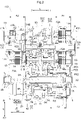
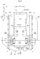
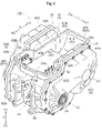
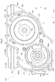
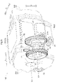
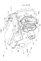
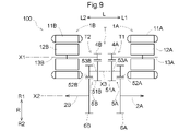
- 1 is a skeleton diagram of a vehicle drive system according to an embodiment; Sectional view of the vehicle drive system according to the embodiment 1 is a plan view of part of a vehicle drive system according to an embodiment; 1 is a perspective view of part of a vehicle drive system according to an embodiment; 1 is a side view of part of a vehicle drive system according to an embodiment; 1 is a perspective view of a case of a vehicle drive system according to an embodiment; 1 is a perspective view of a case of a vehicle drive system according to an embodiment; 1 is a front view of a vehicle drive system according to an embodiment; Skeleton diagram of a vehicle drive system according to another embodiment
- the third cover member 31C corresponds to the "cover member”, and includes the first side wall 40A (specifically, part of the first side wall 40A), the second side wall 40B (specifically, the second part of the side wall 40B), the third side wall 40C, and the fourth side wall 40D correspond to the "wall", the third side wall 40C and the fourth side wall 40D correspond to the "connecting wall", the first partition wall 61A,
- the second partition wall 61B and the third partition wall 61C correspond to "partition walls", and the first storage chamber forming part 62A is "a part other than the partition wall forming part and forms at least a part of the first storage room".
- the second storage chamber forming portion 62B corresponds to the “portion other than the partition wall forming portion and forming at least a part of the second storage chamber”.
- rotary electric machine is used as a concept including motors (electric motors), generators (generators), and motors/generators that function as both motors and generators as necessary.
- overlapping in a particular direction view means that when a virtual straight line parallel to the viewing direction is moved in each direction orthogonal to the virtual straight line, the virtual straight line means that there exists at least a part of a region where the crosses both of the two members.
- the axial arrangement areas overlap means that the axial arrangement area of one member includes at least the axial arrangement area of the other member. It means that part is included.
- driving connection refers to a state in which two rotating elements are connected so as to be able to transmit a driving force, and the two rotating elements are connected so as to rotate together. It includes a state in which two rotating elements are connected so as to be able to transmit driving force via one or more transmission members.
- Such transmission members include various members (for example, shafts, gear mechanisms, belts, chains, etc.) that transmit rotation at the same speed or at different speeds.
- the transmission member may include an engagement device (for example, a friction engagement device, a mesh type engagement device, etc.) that selectively transmits rotation and driving force.
- driving connection it means a state in which three or more rotating elements of the differential gear mechanism are driven and connected without intervening other rotating elements. shall point to
- the vehicle driving device 100 includes a first rotating electrical machine 1A, a second rotating electrical machine 1B, a first output member 2A drivingly connected to a first wheel W1, and a second wheel W2.
- a second output member 2B and a power transmission mechanism T are provided.
- the vehicle drive device 100 further includes a case 3 that houses the first rotating electric machine 1A, the second rotating electric machine 1B, the first output member 2A, the second output member 2B, and the power transmission mechanism T. I have.
- part of the first output member 2A and part of the second output member 2B are exposed to the outside of the case 3.
- FIG. 1A the vehicle driving device 100
- the vehicle drive device 100 further includes a case 3 that houses the first rotating electric machine 1A, the second rotating electric machine 1B, the first output member 2A, the second output member 2B, and the power transmission mechanism T. I have.
- part of the first output member 2A and part of the second output member 2B are exposed to the outside of the case 3.
- the first wheel W1 and the second wheel W2 are a pair of left and right wheels (for example, a pair of left and right front wheels or a pair of left and right rear wheels) of the vehicle (vehicle on which the vehicle drive device 100 is mounted).
- the first output member 2A is connected to rotate integrally with the first wheel W1
- the second output member 2B is connected to rotate integrally with the second wheel W2.
- the first output member 2A is connected to the first wheel W1 via a constant velocity joint, for example
- the second output member 2B is connected to the second wheel W2 via a constant velocity joint, for example.
- the power transmission mechanism T includes a first transmission system T1 that transmits the torque of the first rotating electrical machine 1A to at least the first output member 2A, and a first transmission system T1 that transmits the torque of the second rotating electrical machine 1B to at least the second output member. and a second transmission system T2 that transmits to 2B.
- the vehicle drive device 100 transmits the torque of the first rotating electrical machine 1A to at least the first output member 2A and transmits the torque of the second rotating electrical machine 1B to at least the second output member 2B to drive the vehicle.
- the first rotating electrical machine 1A and the second rotating electrical machine 1B are electrically connected to a power storage device (not shown) via an inverter unit 90, which will be described later.
- the first rotating electric machine 1A and the second rotating electric machine 1B are powered by being supplied with electric power from the power storage device, or supply electric power generated by the inertial force of the vehicle or the like to the power storage device and store it.
- the first rotating electric machine 1A and the second rotating electric machine 1B are provided so as to be rotatable independently of each other.
- the first transmission system T1 is configured to transmit the torque of the first rotating electric machine 1A to both the first output member 2A and the second output member 2B
- the second transmission system T2 It is configured to transmit the torque of the rotating electric machine 1B to both the first output member 2A and the second output member 2B. That is, the portion of the first transmission system T1 on the side opposite to the first rotary electric machine 1A and the portion of the second transmission system T2 on the side opposite to the second rotary electric machine 1B are used as a common transmission system.
- the power transmission mechanism T distributes and transmits the torque of the first rotating electrical machine 1A and the torque of the second rotating electrical machine 1B to the first output member 2A and the second output member 2B.
- the first rotating electric machine 1A and the second rotating electric machine 1B are arranged on the first axis X1, and the first output member 2A and the second output member 2B are arranged on the second axis X2 different from the first axis X1.
- the first axis X1 and the second axis X2 are arranged parallel to each other.
- an axial direction L is defined as a direction parallel to the first axis X1 and the second axis X2.
- the side in the axial direction L where the first rotating electrical machine 1A is arranged with respect to the second rotating electrical machine 1B is defined as an axial first side L1, and the side opposite to the axial direction first side L1 is defined as an axial direction second side. Let it be L2.
- the first transmission system T1 includes a first counter gear mechanism 5A
- the second transmission system T2 includes a second counter gear mechanism 5B.
- the first counter gear mechanism 5A and the second counter gear mechanism 5B are arranged on the third axis X3 different from the first axis X1 and the second axis X2.
- the first axis X1, the second axis X2, and the third axis X3 are arranged parallel to each other.
- the first axis X1, the second axis X2, and the third axis X3 are virtual axes.
- the vehicle drive device 100 is mounted on the vehicle with the axial direction L extending along the left-right direction of the vehicle. Specifically, it is mounted on the vehicle such that the first axial side L1 is on the left side of the vehicle and the second axial side L2 is on the right side of the vehicle.
- the width direction H is defined as a direction orthogonal to the axial direction L when viewed in the vertical direction (viewed along the vertical direction V (vertical direction)). do.
- one side in the width direction H is defined as a first width direction side H1
- the other side in the width direction H is defined as a second width direction side H2.
- the side in the width direction H on which the first axis X1 is arranged with respect to the second axis X2 is defined as a width direction first side H1
- the side opposite to the width direction first side H1 is defined as a width direction second side.
- the width direction H coincides with the longitudinal direction of the vehicle.
- the width direction first side H1 is the vehicle rear side
- the width direction second side H2 is the vehicle front side.
- the first rotating electric machine 1A includes a first stator 11A fixed to the case 3 and a first rotor 12A rotatably supported with respect to the first stator 11A.
- the second rotating electric machine 1B includes a second stator 11B fixed to the case 3 and a second rotor 12B rotatably supported with respect to the second stator 11B.
- the first driving force source that outputs the torque transmitted by the first transmission system T1 is the first rotating electric machine 1A having the first rotor 12A
- the torque transmitted by the second transmission system T2 is
- the output second driving force source is the second rotating electric machine 1B having the second rotor 12B.
- the first rotating electrical machine 1A and the second rotating electrical machine 1B are inner rotor type rotating electrical machines. Therefore, the first rotor 12A is arranged inside the first stator 11A in the radial direction (the radial direction with respect to the first axis X1), and the second rotor 12B is arranged radially inside the second stator 11B (the first axis X1). X1 in the radial direction).
- the first arrangement area A1 which is the arrangement area in the axial direction L of the first rotating electric machine 1A, coincides with the arrangement area in the axial direction L of the first stator 11A.
- a second arrangement area A2 which is the arrangement area in the axial direction L of the rotary electric machine 1B, matches the arrangement area in the axial direction L of the second stator 11B.
- Each of the first stator 11A and the second stator 11B includes a stator core 14 and coil end portions 15 protruding from the stator core 14 on both sides in the axial direction L. As shown in FIG.
- the coil end portion 15 on the first axial side L1 is formed by a portion of the coil wound around the stator core 14 that protrudes from the stator core 14 to the first axial side L1, and the coil end portion 15 on the second axial side L2 is formed. is formed by a portion of a coil wound around the stator core 14 that protrudes from the stator core 14 toward the second side L2 in the axial direction.
- the arrangement areas in the axial direction L of the first stator 11A and the second stator 11B are the ends of the coil end portions 15 on the first axial side L1 and the coil ends on the second axial side L2. It is an area in the axial direction L between the end of the portion 15 on the second axial side L2.
- the outer diameter of the first rotating electrical machine 1A is equal to the outer diameter of the second rotating electrical machine 1B.
- the outer diameter of stator core 14 provided in first stator 11A is equal to the outer diameter of stator core 14 provided in second stator 11B.
- the first transmission system T1 includes a first input gear 4A connected to rotate integrally with the first rotor 12A, and the second transmission system T2 connects to rotate integrally with the second rotor 12B. and a second input gear 4B.
- the first rotor 12A is connected to rotate integrally with the first rotor shaft 13A.
- a first input gear 4A is formed on the outer surface of a portion of the first rotor shaft 13A on the second side L2 in the axial direction from the first rotor 12A.
- the second rotor 12B is connected to rotate integrally with the second rotor shaft 13B.
- a second input gear 4B is formed on the outer surface of a portion of the second rotor shaft 13B on the first side L1 in the axial direction from the second rotor 12B.
- the first transmission system T1 includes the first counter gear mechanism 5A
- the second transmission system T2 includes the second counter gear mechanism 5B
- the first counter gear mechanism 5A includes a first counter input gear 51A meshing with the first input gear 4A and a first counter output gear 52A rotating integrally with the first counter input gear 51A.
- the first counter output gear 52A is connected to rotate integrally with the first counter input gear 51A via a first counter shaft 53A.
- the first counter output gear 52A is arranged on the first side L1 in the axial direction with respect to the first counter input gear 51A.
- the second counter gear mechanism 5B includes a second counter input gear 51B that meshes with the second input gear 4B and a second counter output gear 52B that rotates integrally with the second counter input gear 51B.
- the second counter output gear 52B is connected to rotate integrally with the second counter input gear 51B via a second counter shaft 53B.
- the second counter output gear 52B is arranged on the second side L2 in the axial direction with respect to the second counter input gear 51B.
- the first transmission system T1 includes the first differential input gear 7A
- the second transmission system T2 includes the second differential input gear 7B.
- the first differential input gear 7A is arranged on the second axis X2 and receives the rotation of the first rotating electric machine 1A.
- the second differential input gear 7B is arranged on the second axis X2. is a gear to which the rotation of the second rotating electrical machine 1B is input.
- the first differential input gear 7A is a gear that meshes with the first counter output gear 52A, and the first differential input gear 7A receives the rotation of the first rotating electric machine 1A as the first counter gear mechanism 5A.
- the second differential input gear 7B is a gear that meshes with the second counter output gear 52B, and the rotation of the second rotary electric machine 1B is transmitted to the second differential input gear 7B by the second counter gear. Input via mechanism 5B.
- the first differential input gear 7A is formed to have the same diameter as the second differential input gear 7B.
- the power transmission mechanism T distributes the torque of the first rotating electrical machine 1A and the torque of the second rotating electrical machine 1B to the first output member 2A and the second output member 2B. introduce. Specifically, the power transmission mechanism T transmits the torque of the first rotating electrical machine 1A transmitted to the first differential input gear 7A and the torque of the second rotating electrical machine 1B transmitted to the second differential input gear 7B. , a differential gear mechanism 6 for distributing to the first output member 2A and the second output member 2B.
- the differential gear mechanism 6 includes a first input rotary element drivingly connected to the first differential input gear 7A, a second input rotary element drivingly connected to the second differential input gear 7B, and a first output member 2A. and a second output rotary element drivingly connected to the second output member 2B.
- the order of rotation speed of these four rotary elements is the first input rotary element, the first output rotary element, the second output rotary element, and the second input rotary element.
- the "order of rotational speed” refers to the order of rotational speed in the rotating state of each rotating element.
- the rotation speed of each rotating element changes depending on the rotation state of the differential gear mechanism 6, but the order of the rotation speed of each rotating element is fixed because it is determined by the structure of the differential gear mechanism 6. .
- the order of rotation speed of each rotating element is the same as the order of arrangement in the velocity diagram (also referred to as collinear diagram) of each rotating element.
- the differential gear mechanism 6 is a planetary gear mechanism (specifically, a Ravigneau-type planetary gear mechanism) including four rotating elements.
- the differential gear mechanism 6 includes four rotating elements, a first sun gear S61, a second sun gear S62, a carrier C6, and a ring gear R6.
- the carrier C6 rotatably supports a first pinion gear P61 and a second pinion gear P62 that rotate integrally via a pinion shaft P63.
- the first pinion gear P61 is formed to have a smaller diameter than the second pinion gear P62.
- the first pinion gear P61 meshes with the first sun gear S61
- the second pinion gear P62 meshes with the second sun gear S62 and also meshes with the ring gear R6.
- the ring gear R6 is a first input rotary element drivingly connected to the first differential input gear 7A.
- the ring gear R6 is coupled to rotate integrally with the first differential input gear 7A.
- the first differential input gear 7A is formed on the outer peripheral surface of the first connecting member 8A, and the ring gear R6 is connected to rotate integrally with the first connecting member 8A.
- the second sun gear S62 is a second input rotary element drivingly connected to the second differential input gear 7B.
- the second sun gear S62 is coupled to rotate integrally with the second differential input gear 7B.
- the second differential input gear 7B is formed on the outer peripheral surface of the second connecting member 8B, and the second sun gear S62 is integrated with the second connecting member 8B via the second connecting shaft 9B. connected for rotation.
- the carrier C6 is a first output rotary element drivingly connected to the first output member 2A.
- the carrier C6 is coupled to rotate integrally with the first output member 2A.
- the first sun gear S61 is a second output rotary element drivingly connected to the second output member 2B.
- the first sun gear S61 is coupled to rotate integrally with the second output member 2B.
- the first sun gear S61 is connected to rotate integrally with the second output member 2B via a first connecting shaft 9A.
- the vehicle drive device 100 includes a case 3.
- the case 3 includes a case body member 30, a first cover member 31A, and a second cover member 31B.
- the case body member 30, the first cover member 31A, and the second cover member 31B are joined together, and in this embodiment, are joined together using bolts.
- the first cover member 31A is arranged on the first side L1 in the axial direction with respect to the case main body member 30, and is joined to the case main body member 30 at the first joint J1.
- the first cover member 31A is joined to the case body member 30 so as to close the opening of the case body member 30 on the axial first side L1.
- the second cover member 31B is arranged on the second side L2 in the axial direction with respect to the case main body member 30, and is joined to the case main body member 30 at the second joint J2.
- the second cover member 31B is joined to the case body member 30 so as to close the opening of the case body member 30 on the axial second side L2.
- a first rotating electric machine 1A, a second rotating electric machine 1B, a first output member 2A, a second output member 2B, and power transmission are provided in a space surrounded by the case body member 30, the first cover member 31A, and the second cover member 31B.
- a mechanism T is accommodated. That is, the case 3 includes a first housing chamber 70A in which the first rotating electric machine 1A, the second rotating electric machine 1B, the first output member 2A, the second output member 2B, and the power transmission mechanism T are housed.
- the first housing chamber 70A is formed surrounded by the case body member 30, the first cover member 31A, and the second cover member 31B.
- an oil pump 20 which will be described later, is also accommodated in the first accommodation chamber 70A.
- the case 3 includes a support portion 44 in this embodiment.
- the support portion 44 is formed in a wall shape along a plane orthogonal to the axial direction L, for example.
- the support portion 44 may be a part of the case body member 30 or may be a separate member from the case body member 30 .
- the support portion 44 is arranged between the first rotating electrical machine 1A and the second rotating electrical machine 1B in the axial direction L, and in the present embodiment, the axial direction L between the first rotating electrical machine 1A and the second rotating electrical machine 1B.
- the first rotary electric machine 1A, the first counter gear mechanism 5A, and the first differential input gear 7A are accommodated in a portion of the first accommodation chamber 70A on the first side L1 in the axial direction with respect to the support portion 44.
- a second rotary electric machine 1B, a second counter gear mechanism 5B, and a second differential input gear 7B are housed in a portion of the chamber 70A on the second side L2 in the axial direction with respect to the support portion 44 .
- the differential gear mechanism 6 is housed in a portion of the first housing chamber 70A on the axial first side L1 with respect to the support portion 44 .
- the vehicle drive device 100 includes an inverter unit 90 that drives the first rotating electrical machine 1A and the second rotating electrical machine 1B.
- FIG. 2 shows the inverter unit 90 in a simplified manner
- the inverter unit 90 includes an inverter (inverter circuit) that converts power between DC power and AC power, and parts attached to the inverter.
- the inverter is, for example, a power module in which a plurality of elements (switching elements, etc.) are modularized.
- Components associated with the inverter are, for example, the first terminal block 91A and the second terminal block 91B shown in FIGS. is a smoothing capacitor or the like for smoothing the
- the first axis X1 is arranged above the second axis X2 V1 and on one side in the width direction H (specifically, the first side in the width direction H1). Further, as shown in FIG. 2, the first rotating electric machine 1A and the second rotating electric machine 1B are arranged apart from each other in the axial direction L. As shown in FIG. As shown in FIGS. 2 and 5, the inverter unit 90 is located between the first rotating electric machine 1A and the second rotating electric machine 1B in the axial direction L (when viewed along the axial direction L).
- the inverter unit 90 is arranged above the second axis X2 V1 and on the second axis X2. It is arranged so as to overlap with at least a part of the member that is attached when viewed in the up-down direction.
- the first rotating electric machine 1A and the second rotating electric machine 1B are arranged on the same axis and separated from each other in the axial direction L, the first rotating electric machine 1A and the second rotating electric machine 1B are separated from each other.
- a region between the axial direction L and overlapping with the first rotating electric machine 1A and the second rotating electric machine 1B when viewed in the axial direction tends to become a dead space.
- the first axis X1 is arranged above the second axis X2 and on the first side H1 in the width direction, the area above the second axis X2 V1 is likely to be a dead space.
- the inverter unit 90 can be arranged using two areas that tend to be dead spaces. An increase in size of the vehicle drive device 100 can be suppressed.
- the area V1 above the second axis X2 is also used as the arrangement area for the inverter unit 90. Since a large area for arranging the inverter unit 90 in the vertical direction can be secured, the vertical dimension of the area for arranging the inverter unit 90 can be easily reduced. Therefore, the inverter unit 90 can be arranged in the upper portion of the vehicle drive device 100 while suppressing an increase in size in the vertical direction V of the vehicle drive device 100 .
- the inverter unit 90 is arranged so as to overlap at least portions of the first rotating electrical machine 1A and the second rotating electrical machine 1B that are arranged above the first axis X1 V1 when viewed in the axial direction. (See Figure 5). Also, the positional relationship in the axial direction L between the inverter unit 90 shown in FIG. 2 and each of the first differential input gear 7A and the second differential input gear 7B, and the inverter unit 90 shown in FIG.
- the inverter unit 90 is positioned V1 above the first differential input gear 7A and the second differential input gear 7B, It is arranged so as to overlap with the first differential input gear 7A and the second differential input gear 7B when viewed in the vertical direction. That is, in the present embodiment, the "at least part of the members arranged on the second axis X2" includes the first differential input gear 7A and the second differential input gear 7B. In addition, in the present embodiment, the inverter unit 90 is arranged above the second axis X2 V1 so as to overlap the second axis X2 when viewed in the vertical direction.
- the inverter unit 90 is housed in the case 3 .
- the case 3 includes a second storage chamber 70B that stores the inverter unit 90 in addition to the first storage chamber 70A described above.
- the case 3 includes a case body member 30, a first cover member 31A, a second cover member 31B, and a third cover member 31C. I have it.
- the third cover member 31C is arranged above the case body member 30 V1, and is joined to the case body member 30 so as to close the opening of the case body member 30 facing upward V1 (see FIG. 4). ing.
- the third cover member 31C is joined to the case body member 30 using bolts.
- An inverter unit 90 is accommodated in a space surrounded by the case main body member 30 and the third cover member 31C. That is, the second storage chamber 70B is formed surrounded by the case body member 30 and the third cover member 31C.
- the case body member 30 includes a first side wall 40A forming a side wall on the first side L1 in the axial direction of the second storage chamber 70B and a second side wall in the axial direction of the second storage chamber 70B.
- the second side wall 40B forming the side wall of L2
- the third side wall 40C forming the side wall on the first side H1 in the width direction of the second storage chamber 70B
- the side wall on the second side H2 in the width direction of the second storage chamber 70B are and a fourth side wall 40D.
- the first side wall 40A, the second side wall 40B, the third side wall 40C, and the fourth side wall 40D are formed integrally with the case main body member 30. As shown in FIG.
- the portion of the first side wall 40A on the second side H2 in the width direction is arranged on the first side L1 in the axial direction relative to the portion on the first side H1 in the width direction of the first side wall 40A so as to form a first region 72A, which will be described later. It is In addition, the portion of the second side wall 40B on the second width direction side H2 is located closer to the axial direction second side L2 than the portion of the second side wall 40B on the width direction first side H1 so as to form a second region 72B described later. are placed in
- the second storage chamber 70B is surrounded by a first side wall 40A, a second side wall 40B, a third side wall 40C, a fourth side wall 40D, a third partition wall 61C described later, and a third cover member 31C. formed.
- the third partition wall 61C constitutes the bottom wall of the second storage chamber 70B.
- the portion of the third partition wall 61C on the first widthwise side H1 is arranged below the portion of the third partition wall 61C on the second widthwise side H2 V2, and the second storage chamber 70B.
- the portion on the first widthwise side H1 is formed deeper than the portion on the second widthwise side H2.
- the third side wall 40C (specifically, the lower portion of the third side wall 40C) is inclined toward the widthwise second side H2 toward the lower side V2.
- the case body member 30 is integrally formed with the partition wall forming portion 60, the first accommodation chamber forming portion 62A, and the second accommodation chamber forming portion 62B. That is, the case body member 30 includes a partition wall forming portion 60, a first accommodation chamber forming portion 62A, and a second accommodation chamber forming portion 62B.
- a case main body member 30 is, for example, a casting manufactured using an integral molding technique by casting.
- the partition wall forming part 60 is a part that forms a partition wall that partitions the first storage chamber 70A and the second storage chamber 70B.
- the first storage chamber 70A and the second storage chamber 70B are formed by one partition wall on each of the first axial side L1, the second axial side L2, and the lower side. are separated by Specifically, as shown in FIGS. 2 to 4, the portion of the first storage chamber 70A located on the first side L1 in the axial direction with respect to the second storage chamber 70B (where the first rotating electrical machine 1A is stored). and the second accommodation chamber 70B are partitioned in the axial direction L by the first partition wall 61A.
- a portion of the first side wall 40A in the width direction H (specifically, an intermediate portion in the width direction H) constitutes the first partition wall 61A.
- a portion of the first storage chamber 70A arranged on the second side L2 in the axial direction with respect to the second storage chamber 70B (a portion in which the second rotating electric machine 1B is stored) and the second storage chamber 70B are It is partitioned in the axial direction L by the second partition wall 61B.
- a portion of the second side wall 40B in the width direction H (specifically, an intermediate portion in the width direction H) constitutes the second partition wall 61B.
- the portion of the first storage chamber 70A arranged downward V2 with respect to the second storage chamber 70B and the second storage chamber 70B are partitioned in the vertical direction V by the third partition wall 61C.
- the partition wall forming part 60 forms these three partition walls (the first partition wall 61A, the second partition wall 61B, and the third partition wall 61C in the concrete station).
- the first storage chamber forming portion 62A is a portion other than the partition wall forming portion 60 and forms at least a portion of the first storage chamber 70A. In this embodiment, the first storage chamber forming portion 62A forms part of the first storage chamber 70A as described below.
- the case 3 is formed in a tubular shape extending in the axial direction L and has a peripheral wall portion surrounding the first rotating electric machine 1A (in this embodiment, also surrounding the differential gear mechanism 6).
- the first storage chamber forming portion 62A is a portion of the peripheral wall portion on the second axial side L2 (specifically, a portion of the peripheral wall portion on the second axial side L2 relative to the first joint portion J1). ).
- the case 3 includes a peripheral wall portion which is formed in a cylindrical shape extending in the axial direction L and surrounds the second rotating electrical machine 1B (in this embodiment, also surrounds the oil pump 20), and has a first accommodation chamber forming portion.
- 62A forms a portion of the peripheral wall portion on the first axial side L1 (specifically, a portion of the peripheral wall portion on the first axial side L1 of the second joint J2).
- the case 3 includes a peripheral wall portion (a peripheral wall portion 42 described later) formed in a cylindrical shape extending in the axial direction L and surrounding the first differential input gear 7A and the second differential input gear 7B.
- the accommodation chamber forming portion 62A forms a portion of the peripheral wall portion 42 (specifically, a portion of the peripheral wall portion 42 not formed by the third partition wall 61C).
- the second storage chamber forming portion 62B is a portion other than the partition wall forming portion 60 and forms at least a portion of the second storage chamber 70B.
- the second storage chamber forming portion 62B is a portion of the first side wall 40A that does not constitute the first partition wall 61A (here, the width of the first side wall 40A is parts on both sides in the direction H), parts of the second side wall 40B that do not constitute the second partition wall 61B (here, parts on both sides of the second side wall 40B in the width direction H), a third side wall 40C, and a fourth side wall 40C. It forms a side wall 40D.
- the second storage chamber forming portion 62B serves as a wall portion extending from the partition wall forming portion 60 and serves as the first side wall 40A (specifically, a part of the first side wall 40A, more specifically , portions on both sides in the width direction H of the first side wall 40A), second side walls 40B (specifically, part of the second side walls 40B, more specifically, portions on both sides in the width direction H of the second side walls 40B). portion), a third sidewall 40C, and a fourth sidewall 40D.
- the case 3 includes a third cover member 31C joined to the wall portion extending from the partition wall forming portion 60 .
- the second storage chamber 70B is surrounded by the partition wall forming portion 60, the wall portion, and the third cover member 31C.
- a third cover member 31C is joined to the wall so as to cover the space surrounded by the partition wall forming portion 60 and the wall from above V1.
- the vehicle drive device 100 further includes the case 3, and the case 3 includes the first rotating electrical machine 1A, the second rotating electrical machine 1B, the first output member 2A, the second output member 2B, and a first accommodation chamber 70A that accommodates the power transmission mechanism T, and a second accommodation chamber 70B that accommodates the inverter unit 90.
- the case 3 forms partition walls (in this example, the first partition wall 61A, the second partition wall 61B, and the third partition wall 61C) that partition the first storage chamber 70A and the second storage chamber 70B.
- partition wall forming portion 60 which is a part, a portion other than the partition wall forming portion 60 and forming at least a part of the first storage chamber 70A (first storage chamber forming portion 62A), and the partition wall forming portion 60
- the case main body member 30 is integrally formed with a portion (second storage chamber forming portion 62B) that forms at least a portion of the second storage chamber 70B.
- the member in which the partition wall forming portion 60 is formed has a portion that forms at least a portion of the first storage chamber 70A and a portion that forms at least a portion of the second storage chamber 70B. Therefore, the number of parts of the case 3 can be easily reduced compared to the case where the partition wall forming part 60 is not formed with these two parts. By reducing the number of parts of the case 3, it is possible to reduce the number of joints in the case 3 and reduce the size of the vehicle drive device 100.
- the first storage chamber 70A and the second storage chamber 70B can be partitioned by one partition wall formed by the partition wall forming portion 60 .
- the gap between the partition walls may increase the size of the vehicle drive device 100.
- the first storage chamber 70A and the second storage chamber 70B can be partitioned by one partition wall, so that the vehicle drive device 100 can be easily reduced in size.
- connection path that electrically connects the inverter unit 90 and the rotating electrical machine passes through the through hole formed in the partition wall.
- a seal member is usually provided to seal the clearance of the through hole.
- the vehicle drive device 100 further includes a case 3, and the case 3 includes the first rotating electrical machine 1A, the second rotating electrical machine 1B, the first output member 2A, the second output member 2B, and the power transmission mechanism.
- a first accommodation chamber 70A that accommodates T and a second accommodation chamber 70B that accommodates the inverter unit 90 are provided.
- the width direction H the side on which the first axis X1 is arranged with respect to the second axis X2 is defined as a width direction first side H1, and the side opposite to the width direction first side H1 is defined as a width direction second side H2.
- the second housing chamber 70B includes a first portion 71A that is sandwiched between the first rotating electric machine 1A and the second rotating electric machine 1B in the axial direction L, and the first portion 71A. and a second portion 71B that is a portion on the width direction second side H2.
- the second portion 71B is formed to have a larger dimension in the axial direction L than the first portion 71A.
- a portion of the second portion 71B is arranged so as to overlap the first storage chamber 70A when viewed in the width direction (viewed along the width direction H). .
- the first portion 71A is less subject to restrictions on the dimension in the axial direction L.
- the dimension in the axial direction L can be increased as described above, so that the formation area of the second storage chamber 70B in the vertical direction view can be widened.
- the vehicle drive device 100 is prevented from being enlarged in the vertical direction V, It is possible to widen the formation area of the second storage chamber 70B when viewed in the vertical direction.
- the inverter unit 90 can be arranged in the upper portion of the vehicle drive device 100 while suppressing an increase in size in the vertical direction V of the vehicle drive device 100 .
- the portion of the second portion 71B on the first side L1 in the axial direction (first region 72A, which will be described later) accommodates the first rotating electric machine 1A in the first accommodation chamber 70A when viewed in the width direction.
- a portion of the second portion 71B on the second axial side L2 (a second region 72B to be described later) accommodates the second rotating electric machine 1B in the first accommodation chamber 70A when viewed in the width direction. It is arranged so that it overlaps with the part that is
- the second portion 71B includes a first region 72A, which is a region extended to the first side L1 in the axial direction with respect to the first portion 71A, and a first portion 71A.
- a second region 72B which is a region extended to the second side L2 in the axial direction, is provided.
- the second portion 71B includes a third region 72C, which is a region expanded to the widthwise second side H2 with respect to the first portion 71A, and the third region 72C of the second portion 71B is wider than the third region 72C.
- the region on the first side L1 in the axial direction is the first region 72A
- the region on the second side L2 in the axial direction from the third region 72C in the second portion 71B is the second region 72B.
- a first terminal block 91A for electrically connecting the inverter unit 90 and the first rotating electrical machine 1A is arranged in the first area 72A, and the inverter unit 90 and the second rotating electrical machine 1B are connected to each other.
- a second terminal block 91B for electrically connecting is arranged in the second region 72B.
- the electrical connection with the first rotating electric machine 1A is performed.
- the first terminal block 91A can be arranged at a position in the axial direction L that facilitates connection
- the second terminal block 91B can be arranged at a position in the axial direction L that facilitates electrical connection with the second rotating electric machine 1B.
- the central region (the third region 72C), which is the region of the second portion 71B expanded to the second widthwise side H2 with respect to the first portion 71A, is avoided.
- a first terminal block 91A and a second terminal block 91B are arranged in a region continuous in the width direction H including the central region (third region 72C) of the first portion 71A and the second portion 71B. Therefore, in a region continuous in the width direction H including the central region (third region 72C) of the first portion 71A and the second portion 71B, the components of the inverter unit 90 other than the first terminal block 91A and the second terminal block 91B are arranged. Elements can be arranged, and each component of the inverter unit 90 can be easily arranged appropriately in the second storage chamber 70B.
- each of the first terminal block 91A and the second terminal block 91B includes an inverter-side terminal 92 electrically connected to an inverter (inverter circuit) included in the inverter unit 90. .
- the inverter and each of the first terminal block 91A and the second terminal block 91B are electrically connected inside the second storage chamber 70B.
- each of the first terminal block 91A and the second terminal block 91B includes a rotating electrical machine side terminal 93 electrically connected to the rotating electrical machine.
- the inverter-side terminal 92 and the rotating electric machine-side terminal 93 provided on the first terminal block 91A are electrically connected, and the inverter-side terminal 92 and the rotating electric machine-side terminal 93 provided on the second terminal block 91B are electrically connected.
- the first terminal block 91A has rotary electric machine side terminals 93 similar to the rotary electric machine side terminals 93 provided in the second terminal block 91B.
- the rotating electrical machine side terminal 93 provided on the first terminal block 91A and the first rotating electrical machine 1A (for example, a bus bar connected to the coil provided on the first stator 11A) are electrically connected inside the first housing chamber 70A.
- the rotating electric machine side terminal 93 provided on the second terminal block 91B and the second rotating electric machine 1B are electrically connected inside the first housing chamber 70A. be done.
- the first terminal block 91A and the second terminal block 91B are arranged so as to pass through a partition wall (specifically, a third partition wall 61C) that partitions the first storage chamber 70A and the second storage chamber 70B.
- a partition wall specifically, a third partition wall 61C
- the connection path electrically connecting the inverter unit 90 and the first rotating electrical machine 1A and the connection path electrically connecting the inverter unit 90 and the second rotating electrical machine 1B are formed in the third partition wall 61C. It is formed so as to pass through a through hole (see FIG. 2).
- the through hole through which the first terminal block 91A is inserted is provided with a seal member for sealing the gap of the through hole
- the through hole through which the second terminal block 91B is inserted is provided with the through hole.
- a sealing member is provided for sealing the gap of the hole.
- the case 3 includes a first surrounding wall 41A that surrounds the first rotating electrical machine 1A and a second surrounding wall 41B that surrounds the second rotating electrical machine 1B.
- the first surrounding wall 41A is formed by the portion of the case body member 30 on the axial first side L1 and the first cover member 31A
- the second surrounding wall 41B is formed by the case body member 30 in the axial direction. It is formed by the portion on the second side L2 and the second cover member 31B.
- the first surrounding wall 41A includes a first peripheral wall portion, a first wall portion, and a second wall portion.
- the first peripheral wall portion is a wall portion that is formed in a tubular shape extending in the axial direction L and surrounds the first rotating electric machine 1A (and also surrounds the differential gear mechanism 6 in this embodiment).
- the portion of the first peripheral wall portion on the first axial side L1 is formed by the first cover member 31A
- the portion on the second axial side L2 of the first peripheral wall portion is formed by the case body member 30.
- the first wall is a wall that closes the opening on the first side L1 in the axial direction of the first peripheral wall.
- the first wall is formed by the first cover member 31A.
- a through hole is formed in the first wall portion (first cover member 31A), and the first output member 2A is arranged in this through hole.
- the second wall portion is a wall portion that closes a part of the opening on the axial second side L2 of the first peripheral wall portion, and the first rotary electric machine 1A is located on the axial second side L2 with respect to the first rotary electric machine 1A. are arranged so as to face each other in the axial direction L.
- the second wall portion is formed by the case body member 30 (specifically, the portion of the case body member 30 including the first partition wall 61A).
- the second surrounding wall 41B includes a second peripheral wall portion, a third wall portion, and a fourth wall portion.
- the second peripheral wall portion is a wall portion that is formed in a cylindrical shape extending in the axial direction L and surrounds the second rotating electrical machine 1B (and also surrounds the oil pump 20 in this embodiment).
- the portion of the second peripheral wall portion on the second axial side L2 is formed by the second cover member 31B
- the portion on the axial first side L1 of the second peripheral wall portion is formed by the case body member 30.
- the third wall is a wall that closes the opening on the second axial side L2 of the second peripheral wall.
- the third wall is formed by the second cover member 31B.
- a through hole is formed in the third wall portion (second cover member 31B), and the second output member 2B is arranged in this through hole.
- the fourth wall portion is a wall portion that closes a part of the opening portion on the first axial side L1 of the second peripheral wall portion, and the fourth wall portion closes the second rotating electrical machine 1B on the first axial side L1 with respect to the second rotating electrical machine 1B. are arranged so as to face each other in the axial direction L.
- the fourth wall portion is formed by the case body member 30 (specifically, the portion of the case body member 30 including the second partition wall 61B).
- the first surrounding wall 41A and the second surrounding wall 41B are spaced apart in the axial direction L. Therefore, a recess (the portion where the second storage chamber 70B is formed) is formed between the first surrounding wall 41A and the second surrounding wall 41B in the case 3 (specifically, the case body member 30) in the axial direction L.
- the portion of the case 3 that forms at least a portion of the second storage chamber 70B functions as a reinforcing rib that enhances the rigidity of the recess.
- the third side wall 40C and the fourth side wall 40D of the second storage chamber 70B are formed to connect the first surrounding wall 41A and the second surrounding wall 41B in the axial direction L.
- the third side wall 40C and the fourth side wall 40D (especially the third side wall 40C) function as reinforcing ribs.
- the case 3 includes a first surrounding wall 41A that surrounds the first rotating electrical machine 1A, a second surrounding wall 41B that surrounds the second rotating electrical machine 1B, and a second housing wall.
- a connecting wall in this example, a third side wall 40C and a 4 side walls 40D).
- the connecting wall (in this example, the third side wall 40C and the fourth side wall 40D) forming at least a part of the second storage chamber 70B is connected to the first surrounding wall 41A of the case 3. and the second surrounding wall 41B in the axial direction L to increase the rigidity of the concave portion. Since the case 3 can be reinforced using the connecting wall for forming the second storage chamber 70B in this way, it is easy to ensure the rigidity of the case 3 appropriately.
- the vehicle drive device 100 includes an oil pump 20 that supplies oil to the first rotating electrical machine 1A and the second rotating electrical machine 1B, and an oil cooler 22 that cools the oil.
- the oil pump 20 for example, an electric oil pump driven by an electric motor can be used.
- the type of pump is not particularly limited, and a gear pump, vane pump, screw pump, or the like can be used.
- the oil pump 20 is housed in the first housing chamber 70A.
- a configuration in which the oil pump 20 is not accommodated in the first accommodation chamber 70A (for example, a configuration in which it is attached to the outside of the case 3) may be employed.
- the oil pump 20 (specifically, the suction port of the oil pump 20) is connected via a first oil passage 24A to a strainer 21, which is a filter for removing foreign matter contained in the oil.
- the oil pump 20 sucks the oil stored inside the case 3 through the strainer 21 .
- the oil pump 20 (specifically, the discharge port of the oil pump 20) is connected to the oil cooler 22 via the second oil passage 24B, and the oil discharged from the oil pump 20 passes through the oil cooler 22. After that, it is supplied to the first rotating electrical machine 1A and the second rotating electrical machine 1B.
- the first oil passage 24A and the second oil passage 24B are formed using oil pipes, for example.
- the oil cooler 22 is configured to cool the oil by heat exchange between the oil and refrigerant (for example, cooling water, air, etc.).
- the oil cooler 22 is a water-cooled oil cooler that uses cooling water as a coolant.
- FIGS. and a piping member 23 for discharging cooling water from the oil cooler 22 are connected.
- the gear arranged on the outermost side R2 in the radial direction R (radial direction with respect to the second axis X2) (in other words, the gear with the largest diameter) is defined as the "first outer gear”, and among the gears arranged on the second axis X2 and constituting the second transmission system T2, the gear arranged on the outermost side R2 in the radial direction R shall be referred to as a "second peripheral gear".
- the first differential input gear 7A is the first peripheral gear
- the second differential input gear 7B is the second peripheral gear.
- the 1st differential input gear 7A and the 2nd differential input gear 7B are spaced apart in the axial direction L, and are arrange
- the first differential input gear 7A and the second differential input gear 7B are arranged apart in the axial direction L, the first differential input gear 7A and the second differential input gear A region between the gear 7B in the axial direction L and overlapping with at least one of the first differential input gear 7A and the second differential input gear 7B when viewed in the axial direction tends to be a dead space.
- the oil cooler 22 since the oil cooler 22 is arranged as described above, the oil cooler 22 can be arranged using a region that tends to become a dead space. An increase in size of the drive device 100 can be suppressed.
- the oil cooler 22 is located on the width direction second side H2 with respect to the second axis X2 and on the axial direction L between the first differential input gear 7A and the second differential input gear 7B. and overlaps at least one of the first differential input gear 7A and the second differential input gear 7B when viewed in the axial direction.
- the first differential input gear 7A is formed to have the same diameter as the second differential input gear 7B
- the oil cooler 22 has the same diameter as the first differential input gear 7A and the second differential input gear 7B when viewed in the axial direction. It is arranged so as to overlap with both of the two differential input gears 7B.
- the case 3 includes a peripheral wall portion 42 covering the outer side R2 in the radial direction R with respect to the first differential input gear 7A and the second differential input gear 7B.
- the peripheral wall portion 42 is formed by the case main body member 30 (specifically, the first storage chamber forming portion 62A and the third partition wall 61C).
- a concave portion 43 recessed inward R1 in the radial direction R is formed in a portion of the peripheral wall portion 42 corresponding to the axial direction L between the first differential input gear 7A and the second differential input gear 7B.
- the recess 43 is formed in a portion of the peripheral wall portion 42 on the second widthwise side H2 so as to be recessed on the first widthwise side H1.
- At least part of the oil cooler 22 is arranged to be accommodated in the recess 43 . That is, the oil cooler 22 is attached to the outside of the case 3 so that at least part of the oil cooler 22 is accommodated in the recess 43 .
- "to be accommodated in the recessed portion 43" means to be covered by the peripheral wall portion 42 when viewed from any side in the axial direction L.
- the entire main body of the oil cooler 22 (the portion where heat is exchanged between the oil and the refrigerant) is arranged to fit in the recess 43 .
- the vehicle drive device 100 includes the case 3 that houses the first rotating electric machine 1A, the second rotating electric machine 1B, the first output member 2A, the second output member 2B, and the power transmission mechanism T. is further provided.
- the case 3 includes a peripheral wall portion 42 covering the outer side R2 in the radial direction R with respect to the first differential input gear 7A and the second differential input gear 7B.
- a concave portion 43 recessed inward R1 in the radial direction R is formed in a portion corresponding to the axial direction L between the differential input gear 7B.
- At least part of the oil cooler 22 is arranged to be accommodated in the recess 43 .
- the oil cooler 22 is often attached to the outside of the case 3.
- the vehicle drive device 100 is likely to have a shape in which the portion to which the oil cooler 22 is attached protrudes outward with respect to the surrounding portion, and the vehicle drive device 100 is located on the side to which the oil cooler 22 is attached. 100 can be upsized.
- the peripheral wall portion 42 of the case 3 utilizes a region that tends to become a dead space between the first differential input gear 7A and the second differential input gear 7B in the axial direction L.
- the oil cooler 22 can be arranged such that a recess 43 is formed and at least part of the oil cooler 22 is accommodated in the recess 43 . Therefore, the oil cooler 22 can be attached to the outside of the case 3 while suppressing an increase in the size of the vehicle drive device 100 .
- a first arrangement area A1 which is an arrangement area in the axial direction L of the first rotating electric machine 1A
- a third arrangement area which is an arrangement area in the axial direction L of the differential gear mechanism 6 It overlaps with area A3.
- the arrangement area in the axial direction L of the carrier C6 provided in the differential gear mechanism 6 (the axial direction L between the end of the carrier C6 on the first axial side L1 and the end on the second axial side L2) area) is set as a third arrangement area A3.
- the second arrangement area A2 which is the arrangement area in the axial direction L of the second rotating electric machine 1B
- the fourth arrangement area A4 which is the arrangement area in the axial direction L of the oil pump 20
- the oil cooler 22 is arranged so as to overlap at least one of the differential gear mechanism 6 and the oil pump 20 when viewed in the axial direction.
- the oil cooler 22 is arranged so as to overlap the differential gear mechanism 6 and not overlap the oil pump 20 when viewed in the axial direction (in FIG.
- the oil pump 20 omitted
- a configuration in which the oil cooler 22 overlaps with the oil pump 20 and does not overlap with the differential gear mechanism 6 when viewed in the axial direction and a configuration in which the oil cooler 22 overlaps the differential gear mechanism 6 and the oil pump when viewed in the axial direction 20 can also be arranged so as to overlap.
- the first driving force source (the driving force source that outputs the torque transmitted by the first transmission system T1) is the first rotating electric machine 1A having the first rotor 12A.
- the second driving force source (driving force source that outputs torque transmitted by the second transmission system T2) is the second rotating electrical machine 1B having the second rotor 12B.
- the first transmission system T1 includes a first input gear 4A connected to rotate integrally with the first rotor 12A, a third gear meshing with the first gear, and a fourth gear rotating integrally with the third gear.
- the second transmission system T2 includes a second input gear 4B connected to rotate integrally with the second rotor 12B, and a second input gear 4B that meshes with the second gear.
- the first differential input gear 7A is a gear that meshes with the first counter output gear 52A
- the second differential input gear 7B is a gear that meshes with the second counter output gear 52B.
- the power transmission mechanism T transmits the torque of the first rotating electrical machine 1A transmitted to the first differential input gear 7A and the torque of the second rotating electrical machine 1B transmitted to the second differential input gear 7B to the first output member. 2A and a differential gear mechanism 6 that distributes to the second output member 2B.
- the oil cooler 22 is arranged so as to overlap at least one of the differential gear mechanism 6 and the oil pump 20 when viewed in the axial direction.
- the first differential The diameters of the input gear 7A and the second differential input gear 7B tend to be large.
- the oil cooler is operated by utilizing the region between the first differential input gear 7A and the second differential input gear 7B in the axial direction L, which tends to become a dead space. 22 can be placed. Therefore, even if the diameters of the first differential input gear 7A and the second differential input gear 7B are large, the arrangement of the oil cooler 22 can prevent the vehicle drive device 100 from being further enlarged. can.
- the differential gear mechanism 6 and the oil pump 20 are arranged separately on both sides in the axial direction L in this way, it is possible to prevent one side of the vehicle drive device 100 in the axial direction L from becoming larger than the other side. Therefore, the shape of the vehicle drive device 100 can be easily made into a shape that is easy to mount on the vehicle.
- the oil cooler 22 is arranged so as to overlap at least one of the differential gear mechanism 6 and the oil pump 20 when viewed in the axial direction. It is easy to keep the dimension in the axial direction small.
- a second oil passage 24B which is an oil passage connecting the oil pump 20 and the oil cooler 22, connects the first differential input gear 7A and the second differential input gear 7B. Arranged so as to pass through an area between the axial direction L and overlapping with at least one of the first differential input gear 7A and the second differential input gear 7B (both in the example shown in FIG. 6) when viewed in the axial direction. It is
- the second oil passage 24B which is the oil passage connecting the oil pump 20 and the oil cooler 22, is arranged as described above.
- the oil passages can also be arranged using a region that tends to become a dead space between the first differential input gear 7A and the second differential input gear 7B in the axial direction L. Therefore, it is easy to reduce the size of the vehicle drive device 100 .
- the second oil passage 24B is located below the second axis X2 V2 and between the first differential input gear 7A and the second differential input gear 7B in the axial direction L. It is arranged so as to pass through a region that overlaps at least one of the first differential input gear 7A and the second differential input gear 7B when viewed in the axial direction.
- a third oil passage 24C described below is positioned V1 above the second axis X2 and between the first differential input gear 7A and the second differential input gear 7B. It is arranged so as to pass through a region between the axial direction L and overlapping with at least one of the first differential input gear 7A and the second differential input gear 7B when viewed in the axial direction.
- a third oil passage 24C which is an oil passage connecting the oil cooler 22 and both the first rotating electrical machine 1A and the second rotating electrical machine 1B, is connected to the first differential input.
- a third oil passage 24C which is an oil passage connecting the oil cooler 22 and both the first rotating electrical machine 1A and the second rotating electrical machine 1B, is connected to the first differential input.
- the gear 7A and the second differential input gear 7B in the axial direction L at least one of the first differential input gear 7A and the second differential input gear 7B (in the example shown in FIG. 7, , both) are arranged to pass through the overlapping region.
- the third oil passage 24C which is the oil passage connecting the oil cooler 22 and both the first rotating electrical machine 1A and the second rotating electrical machine 1B, is arranged as described above.
- the dead space between the first differential input gear 7A and the second differential input gear 7B in the axial direction L is also present in the oil passage connecting the oil cooler 22 and both the first rotating electrical machine 1A and the second rotating electrical machine 1B. It can be arranged using an area that tends to be Therefore, it is easy to reduce the size of the vehicle drive device 100 .
- the oil passages connecting the oil cooler 22 and both the first rotating electric machine 1A and the second rotating electric machine 1B can be connected to the first rotating electric machine 1A and the second rotating electric machine 1A. It branches to both sides in the axial direction L from between the electric machine 1B in the axial direction L (for example, from the central portion in the axial direction L between the first rotary electric machine 1A and the second rotary electric machine 1B), and the first rotary electric machine It can be formed so as to reach each of 1A and the second rotating electric machine 1B.
- the length of the oil passage connecting the oil cooler 22 and the first rotating electric machine 1A and the length of the oil passage connecting the oil cooler 22 and the second rotating electric machine 1B can be easily brought to the same length, and the pressure in these two oil passages is reduced. Easy to even out losses. For example, by shortening the length of these two oil passages to the same extent, the pressure loss in these two oil passages can be reduced to the same extent.
- the configuration of the third oil passage 24C in the vehicle drive system 100 of this embodiment will be specifically described below.
- the third oil passage 24C includes the following common oil passage 25, first branch oil passage 26A, second branch oil passage 26B, third branch oil passage 26C, first cooling oil passage 27A, second cooling oil passage 27B, It has a third cooling oil passage 27C, a first lubricating oil passage 28A, and a second lubricating oil passage 28B.
- Each of these oil passages provided in the third oil passage 24 ⁇ /b>C is formed using an oil pipe, or formed in the wall portion of the case 3 , for example.
- the upstream end of the common oil passage 25 is connected to the oil cooler 22 .
- the common oil passage 25 is between the first differential input gear 7A and the second differential input gear 7B in the axial direction L, and is located between the first differential input gear 7A and the second differential input gear 7B when viewed in the axial direction. 7B (both sides in the example shown in FIG. 7).
- the common oil passage 25 is arranged, for example, in the axial direction L central portion between the first rotating electrical machine 1A and the second rotating electrical machine 1B.
- a first branched oil passage 26A, a second branched oil passage 26B, and a third branched oil passage 26C are connected in parallel to a downstream portion of the common oil passage 25.
- the discharged oil passes through the common oil passage 25 and is supplied to each of the first branch oil passage 26A, the second branch oil passage 26B, and the third branch oil passage 26C.
- the first branch oil passage 26A is formed so as to extend from the connection portion with the common oil passage 25 to the axial first side L1, and the second branch oil passage 26B extends from the connection portion with the common oil passage 25 in the axial direction.
- the third branch oil passage 26C is formed to extend to the second side L2, and the third branch oil passage 26C is formed to extend to the width direction first side H1 from the connection portion with the common oil passage 25. As shown in FIG. Therefore, the third oil passage 24 ⁇ /b>C is formed to branch from the common oil passage 25 to both sides in the axial direction L and to the first widthwise side H ⁇ b>1 .
- the oil supplied from the common oil passage 25 to the first branch oil passage 26A is supplied to the first rotating electric machine 1A.
- a first cooling oil passage 27A and a first lubricating oil passage 28A are connected in parallel to a downstream portion of the first branch oil passage 26A, and the oil in the first branch oil passage 26A is It is supplied to each of the first cooling oil passage 27A and the first lubricating oil passage 28A.
- the oil in the first cooling oil passage 27A is supplied to the first rotating electrical machine 1A, and the first rotating electrical machine 1A is cooled by the oil.
- the oil in the first lubricating oil passage 28A is supplied to parts requiring lubrication such as bearings that support the first rotor shaft 13A, and the parts requiring lubrication are lubricated by the oil.
- an oil supply portion 97 for supplying oil to the first rotating electrical machine 1A is provided above the first rotating electrical machine 1A V1.
- the oil supply portion 97 supplies oil supplied from the first cooling oil passage 27A to the first rotating electric machine 1A.
- the oil supply part 97 is a supply pipe extending along the axial direction L, and the oil inside the supply pipe is supplied from a hole (not shown) formed in the supply pipe to the first rotating electric machine. 1A (specifically, the first stator 11A).
- the oil in the first cooling oil passage 27A is supplied to the first rotating electric machine 1A via the oil supply portion 97.
- two oil supply portions 97 are provided on both sides in the width direction H across the first axis X1, and correspondingly, two first cooling oil passages 27A are provided in the first It is connected to the branch oil passage 26A (see FIG. 7).
- the oil supplied from the common oil passage 25 to the second branch oil passage 26B is supplied to the second rotating electric machine 1B.
- a second cooling oil passage 27B and a second lubricating oil passage 28B are connected in parallel to a downstream portion of the second branch oil passage 26B, and the oil in the second branch oil passage 26B is It is supplied to each of the second cooling oil passage 27B and the second lubricating oil passage 28B.
- the oil in the second cooling oil passage 27B is supplied to the second rotating electrical machine 1B, and the second rotating electrical machine 1B is cooled by the oil.
- the oil in the second lubricating oil passage 28B is supplied to parts requiring lubrication such as bearings that support the second rotor shaft 13B, and the parts requiring lubrication are lubricated by the oil.
- an oil supply unit similar to the oil supply unit 97 shown in FIG. is supplied to the second rotating electric machine 1B via the oil supply unit.
- the oil supplied from the common oil passage 25 to the third branch oil passage 26C is supplied to both the first rotating electric machine 1A and the second rotating electric machine 1B. Specifically, as shown in FIG. 2, between the first rotating electrical machine 1A and the second rotating electrical machine 1B in the axial direction L (in this example, the first rotating electrical machine 1A and the second rotating electrical machine 1B) on the first axis X1.
- a third cooling oil passage 27C to which oil is supplied from the third branch oil passage 26C is arranged in the central portion in the axial direction L between the electric machine 1B.
- the connection portion of the third branch oil passage 26C with the third cooling oil passage 27C is formed in the support portion 44 .
- the oil in the third cooling oil passage 27C is supplied to the first rotating electrical machine 1A and the second rotating electrical machine 1B, and the first rotating electrical machine 1A and the second rotating electrical machine 1B are cooled by the oil.
- the end of the third cooling oil passage 27C on the first axial side L1 communicates with the inside of the hollow first rotor shaft 13A, and the end of the third cooling oil passage 27C on the second axial side L2 is hollow. is communicated with the inside of the second rotor shaft 13B. Therefore, the oil supplied from the third branched oil passage 26C to the third cooling oil passage 27C branches to both sides in the axial direction L and is supplied to the inside of the first rotor shaft 13A and the inside of the second rotor shaft 13B. be.
- the oil supplied from the third cooling oil passage 27C to the inside of the first rotor shaft 13A is supplied to the first rotating electrical machine 1A, and the first rotating electrical machine 1A is cooled by the oil.
- heat exchange between oil inside the first rotor shaft 13A and the first rotor shaft 13A cools the first rotor 12A fixed to the first rotor shaft 13A.
- the oil discharged from the hole formed in the first rotor shaft 13A is supplied to the coil end portion 15 provided in the first stator 11A to cool the coil end portion 15 .
- the oil supplied from the third cooling oil passage 27C to the inside of the second rotor shaft 13B is supplied to the second rotating electrical machine 1B, and the second rotating electrical machine 1B is cooled by the oil.
- heat exchange between oil inside the second rotor shaft 13B and the second rotor shaft 13B cools the second rotor 12B fixed to the second rotor shaft 13B.
- oil discharged from a hole formed in the second rotor shaft 13B is supplied to the coil end portion 15 provided in the second stator 11B to cool the coil end portion 15 .
- the configuration in which the first terminal block 91A is arranged in the first area 72A and the second terminal block 91B is arranged in the second area 72B has been described as an example.
- the present disclosure is not limited to such a configuration, and one or both of the first terminal block 91A and the second terminal block 91B are arranged in the third region 72C of the second portion 71B, or the first terminal One or both of the base 91A and the second terminal block 91B may be arranged on the first portion 71A.
- the second portion 71B is formed to have a larger dimension in the axial direction L than the first portion 71A, and a portion of the second portion 71B is the first storage chamber 70A when viewed in the width direction. has been described as an example. However, the present disclosure is not limited to such a configuration. A configuration that does not include a portion that overlaps with the storage chamber 70A is also possible. That is, the second portion 71B may be configured without the first region 72A and the second region 72B.
- the first peripheral gear (the first differential input gear 7A in the above embodiment) and the second peripheral gear (the second differential input gear in the above embodiment) in the peripheral wall portion 42 A configuration in which the recess 43 is formed in the portion corresponding to the axial direction L with the gear 7B) and at least a part of the oil cooler 22 is arranged to be accommodated in the recess 43 has been described as an example.
- the present disclosure is not limited to such a configuration in which the oil cooler 22 is attached to the outside of the case 3, and a configuration in which the oil cooler 22 is accommodated in the first accommodation chamber 70A is also possible.
- An overlapping configuration has been described as an example.
- the present disclosure is not limited to such a configuration.
- a configuration in which the arrangement regions in the axial direction L do not overlap, or a configuration in which these are combined can also be used.
- the arrangement areas in the axial direction L of the first rotating electrical machine 1A and the oil pump 20 may overlap, and the arrangement areas in the axial direction L of the second rotating electrical machine 1B and the differential gear mechanism 6 may overlap. can.
- the configuration in which the oil cooler 22 overlaps at least one of the differential gear mechanism 6 and the oil pump 20 as viewed in the axial direction has been described as an example.
- the present disclosure is not limited to such a configuration, and a configuration in which the oil cooler 22 overlaps neither the differential gear mechanism 6 nor the oil pump 20 when viewed in the axial direction may be employed.
- the second oil passage 24B which is the oil passage connecting the oil pump 20 and the oil cooler 22, is connected to the first peripheral gear (the first differential input gear 7A in the above embodiment).
- a region between the second peripheral gear (the second differential input gear 7B in the above embodiment) in the axial direction L and overlapping with at least one of the first peripheral gear and the second peripheral gear when viewed in the axial direction has been described as an example.
- the present disclosure is not limited to such a configuration, and a configuration in which the second oil passage 24B does not pass through the above region can also be employed.
- the third oil passage 24C which is an oil passage connecting the oil cooler 22 and both the first rotating electrical machine 1A and the second rotating electrical machine 1B, is connected to the first peripheral gear (in the above embodiment, , the first differential input gear 7A) and the second peripheral gear (in the above embodiment, the second differential input gear 7B) in the axial direction L, between the first peripheral gear and the second
- the configuration has been described as an example in which it is arranged so as to pass through a region that overlaps with at least one of the two outer peripheral gears.
- the present disclosure is not limited to such a configuration, and a configuration in which the third oil passage 24C does not pass through the above region can also be employed.
- the first peripheral gear (the first differential input gear 7A in the above embodiment) is the same as the second peripheral gear (the second differential input gear 7B in the above embodiment).
- the configuration has been described as an example in which the diameter is formed.
- the present disclosure is not limited to such a configuration, and a configuration in which the first outer peripheral gear is formed with a larger diameter or a smaller diameter than the second outer peripheral gear is also possible.
- the oil cooler 22 is located between the first and second peripheral gears in the axial direction L and between the first and second peripheral gears when viewed in the axial direction. It is good also as a structure arrange
- one or both of the second oil passage 24B and the third oil passage 24C are between the first and second peripheral gears in the axial direction L, It may be arranged so as to pass through a region overlapping only one of the first outer peripheral gear and the second outer peripheral gear when viewed in the axial direction.
- the differential gear mechanism 6 is a planetary gear mechanism having four rotating elements.
- the present disclosure is not limited to such a configuration, and for example, the differential gear mechanism 6 includes two planetary gear mechanisms that are integrally provided with four rotating elements and coupled to differentially operate. It can also be a mechanism.
- the first transmission system T1 includes the first counter gear mechanism 5A
- the second transmission system T2 includes the second counter gear mechanism 5B
- the present disclosure is not limited to such a configuration, and a configuration in which the first transmission system T1 does not include the first counter gear mechanism 5A and the second transmission system T2 does not include the second counter gear mechanism 5B is also possible.
- the first counter gear mechanism 5A instead of the first counter gear mechanism 5A, an idler gear meshing with both the first input gear 4A and the first differential input gear 7A is provided, and instead of the second counter gear mechanism 5B, the second input gear 4B and A configuration may be employed in which an idler gear that meshes with both of the second differential input gears 7B is provided.
- the first differential input gear 7A may mesh with the first input gear 4A
- the second differential input gear 7B may mesh with the second input gear 4B.
- the first transmission system T1 transmits the torque of the first rotating electrical machine 1A to both the first output member 2A and the second output member 2B
- the second transmission system T2 transmits the second
- the configuration in which the torque of the rotary electric machine 1B is transmitted to both the first output member 2A and the second output member 2B has been described as an example.
- the present disclosure is not limited to such a configuration, and the first transmission system T1 transmits the torque of the first rotating electric machine 1A only to the first output member 2A, It is also possible to adopt a configuration in which the torque of 1B is transmitted only to the second output member 2B. That is, the power transmission mechanism T may be configured without the differential gear mechanism 6 . An example of such a configuration is shown in FIG.
- the first transmission system T1 serves as a gear arranged on the second axis X2 and to which the rotation of the first rotating electrical machine 1A is input, which rotates integrally with the first output member 2A.
- the second transmission system T2 is arranged on the second axis X2 and serves as a gear to which the rotation of the second rotating electric machine 1B is input. Includes gear 6B.
- the first output gear 6A meshes with the first counter output gear 52A
- the second output gear 6B meshes with the second counter output gear 52B.
- the first output gear 6A is the first peripheral gear
- the second output gear 6B is the second peripheral gear.
- the oil cooler 22 includes the first peripheral gear (the first differential input gear 7A in the above embodiment) and the second peripheral gear (the second differential input gear in the above embodiment).
- the configuration has been described as an example in which the gear 7B) is positioned between the gear 7B) in the axial direction L and overlaps with at least one of the first outer peripheral gear and the second outer peripheral gear when viewed in the axial direction.
- the present disclosure is not limited to such a configuration, and for example, a configuration in which the oil cooler 22 overlaps neither the first outer peripheral gear nor the second outer peripheral gear when viewed in the axial direction may be employed.
- the configuration in which the vehicle drive system 100 includes the oil pump 20 and the oil cooler 22 has been described as an example.
- the present disclosure is not limited to such a configuration, and the vehicle drive system 100 may be configured without one or both of the oil pump 20 and the oil cooler 22 .
- the inverter unit 90 is arranged above the second axis X2 V1 and overlaps at least a part of the members arranged on the second axis X2 when viewed in the vertical direction.
- the configuration has been described as an example. However, the present disclosure is not limited to such a configuration, and a configuration in which the inverter unit 90 is arranged so as not to overlap any of the members arranged on the second axis X2 when viewed in the vertical direction is also possible.
- a vehicle drive system (100) comprising a power transmission mechanism (T) including a first transmission system ( T1), and a second transmission system (T2) that transmits the torque of the second rotating electrical machine (1B) to at least the second output member (2B), wherein the first rotating electrical machine (1A) and the second A two-rotating electric machine (1B) is arranged on a first axis (X1), and the first output member (2A) and the second output member (2B) are arranged on a second axis different from the first axis (X1).
- the first axis (X1) is arranged on the axis (X2) and parallel to the first axis (X1) and the second axis (X2) as the axial direction (L).
- X2) above (V1) the first rotating electrical machine (1A) and the second rotating electrical machine (1B) are spaced apart in the axial direction (L), and the inverter unit (90 ) is between the first rotating electric machine (1A) and the second rotating electric machine (1B) in the axial direction (L) and is the first rotating electric machine in an axial view along the axial direction (L).
- the electric machine (1A) and the second electric machine (1B) are arranged so as to overlap, and the case (3) includes the first electric machine (1A), the second electric machine (1B), and the first output.
- the case (3) is a partition wall that is a portion forming partition walls (61A, 61B, 61C) that partition the first storage chamber (70A) and the second storage chamber (70B) a formation portion (60), a portion (62A) other than the partition wall formation portion (60) and forming at least a portion of the first storage chamber (70A), and the partition wall formation portion (60)
- the part (62A) forming at least part of the first storage chamber (70A) and at least part of the second storage chamber (70B) are formed in the member in which the partition wall forming part (60) is formed. is also formed, the first rotating electric machine (1A ), the second rotating electric machine (1B), the power transmission mechanism (T), and the inverter unit (90).
- the inverter unit (90) can be arranged using the area that tends to become a dead space. It is possible to suppress
- the second storage chamber forming portion (62B) includes wall portions (40A, 40B, 40C, 40D) extending from the partition wall forming portion (60), and the case (3) includes the A cover member (31C) joined to the walls (40A, 40B, 40C, 40D) is provided. 40C, 40D) and the cover member (31C).
- the second storage chamber (70B) can be properly formed by the case body member (30) and the cover member (31C).
- first axis (X1) is aligned with the second
- the inverter unit (90) is arranged on one side of the width direction (H) relative to the axis (X2), and the inverter unit (90) is above (V1) the second axis (X2) and extends along the second axis (X2 ) is preferably arranged so as to overlap at least a part of the members arranged above when viewed in the vertical direction.
- the region above the second axis (X2) (V1) is also By using it as an arrangement area for the inverter unit (90), it is possible to secure a large arrangement area for the inverter unit (90) in the vertical direction. easy to suppress. Therefore, the inverter unit (90) can be arranged in the upper portion of the vehicle drive device (100) while suppressing an increase in the size of the vehicle drive device (100) in the vertical direction (V).
- the side of the width direction (H) on which the first axis (X1) is arranged with respect to the second axis (X2) is defined as a width direction first side (H1)
- the width direction first side ( H1) is defined as a widthwise second side (H2)
- the second housing chamber (70B) extends in the axial direction ( L), and a second portion (71B) that is on the second widthwise side (H2) of the first portion (71A).
- the second portion (71B) is formed to have a larger dimension in the axial direction (L) than the first portion (71A), and a portion of the second portion (71B) is formed to be larger in the width direction ( H) is preferably arranged so as to overlap with the first storage chamber (70A) when viewed in the width direction.
- the dimension in the axial direction (L) is larger than that of the first portion (71A) interposed between the first rotating electrical machine (1A) and the second rotating electrical machine (1B) in the axial direction (L).
- the dimension in the axial direction (L) of the second portion (71B) which is less likely to be restricted, can be increased to widen the formation area of the second storage chamber (70B) when viewed in the vertical direction.
- the vehicle drive device (100) is large in the vertical direction (V).
- the inverter unit (90) can be arranged in the upper portion of the vehicle drive device (100) while suppressing an increase in the size of the vehicle drive device (100) in the vertical direction (V).
- the side of the axial direction (L) on which the first rotating electrical machine (1A) is arranged with respect to the second rotating electrical machine (1B) is defined as an axial first side (L1).
- the side opposite to the side (L1) is defined as the axial second side (L2), and the second portion (71B) extends toward the axial first side (L1) with respect to the first portion (71A).
- the A first terminal block (91A) for electrically connecting the inverter unit (90) and the first rotating electric machine (1A) is arranged in the first area (72A), and is connected to the inverter unit (90).
- a second terminal block (91B) for electrically connecting the second rotating electric machine (1B) is preferably arranged in the second region (72B).
- the positional relationship in the axial direction (L) between the first rotating electrical machine (1A) and the second rotating electrical machine (1B) is taken into account, and electrical connection with the first rotating electrical machine (1A) is facilitated.
- a first terminal block (91A) is arranged at a position in the axial direction (L)
- a second terminal block (91B) is arranged at a position in the axial direction (L) that facilitates electrical connection with the second rotating electric machine (1B). can do.
- the second portion (71B) is arranged so as to avoid the central region (72C), which is a region expanded to the widthwise second side (H2) with respect to the first portion (71A).
- One terminal block (91A) and a second terminal block (91B) can be arranged. Therefore, the first terminal block (91A) of the inverter unit (90) and the first terminal block (91A) of the inverter unit (90) and the second Components other than the two-terminal block (91B) can be arranged, and each component of the inverter unit (90) can be easily arranged appropriately in the second storage chamber (70B).
- the case (3) includes a first surrounding wall (41A) that surrounds the first rotating electrical machine (1A) and a second surrounding wall (41B) that surrounds the second rotating electrical machine (1B). ) and a portion that forms at least a portion of the second storage chamber (70B) and connects the first surrounding wall (41A) and the second surrounding wall (41B) in the axial direction (L). and connecting walls (40C, 40D) formed as follows.
- the connecting walls (40C, 40D) forming at least part of the second storage chamber (70B) are connected to the first surrounding wall (41A) and the second surrounding wall (41B) of the case (3). It can function as a reinforcing rib that enhances the rigidity of the recess formed between the axial directions (L). Since the connecting walls (40C, 40D) for forming the second storage chamber (70B) can be used to reinforce the case (3) in this way, it is easy to appropriately secure the rigidity of the case (3). .
- 1A first rotating electrical machine
- 1B second rotating electrical machine
- 2A first output member
- 2B second output member
- 3 case, 30: case body member
- 31C third cover member (cover member)
- 40A first side wall (wall portion)
- 40B second side wall (wall portion)
- 40C third side wall (wall portion, connecting wall)
- 40D fourth side wall (wall portion, connecting wall)
- 41A first enclosure Wall
- 41B Second surrounding wall
- 60 Partition wall forming part
- 61A First partition wall (partition wall)
- 61B Second partition wall (partition wall)
- 61C Third partition wall (partition wall)
- 62A First storage chamber forming portion (a portion other than the partition wall forming portion and forming at least a part of the first storage chamber)
- 62B Second storage chamber forming portion (a portion other than the partition wall forming portion) part forming at least part of the second storage chamber)
- 70A first storage chamber
- 70B second storage chamber
- 71A first portion
Landscapes
- Engineering & Computer Science (AREA)
- Power Engineering (AREA)
- General Engineering & Computer Science (AREA)
- Mechanical Engineering (AREA)
- Chemical & Material Sciences (AREA)
- Transportation (AREA)
- Combustion & Propulsion (AREA)
- Microelectronics & Electronic Packaging (AREA)
- Hybrid Electric Vehicles (AREA)
- Arrangement Or Mounting Of Propulsion Units For Vehicles (AREA)
- Retarders (AREA)
- General Details Of Gearings (AREA)
- Motor Or Generator Frames (AREA)
- Connection Of Motors, Electrical Generators, Mechanical Devices, And The Like (AREA)
- Electric Propulsion And Braking For Vehicles (AREA)
Abstract
Description
次に、車両用駆動装置のその他の実施形態について説明する。
以下、上記において説明した車両用駆動装置の概要について説明する。
Claims (6)
- 第1回転電機と、第2回転電機と、第1車輪に駆動連結される第1出力部材と、第2車輪に駆動連結される第2出力部材と、動力伝達機構と、前記第1回転電機及び前記第2回転電機を駆動するインバータユニットと、ケースと、を備えた車両用駆動装置であって、
前記動力伝達機構は、前記第1回転電機のトルクを少なくとも前記第1出力部材に伝達する第1伝達系と、前記第2回転電機のトルクを少なくとも前記第2出力部材に伝達する第2伝達系と、を備え、
前記第1回転電機及び前記第2回転電機が、第1軸上に配置され、
前記第1出力部材及び前記第2出力部材が、前記第1軸とは異なる第2軸上に配置され、
前記第1軸及び前記第2軸に平行な方向を軸方向として、
前記第1軸は、前記第2軸よりも上方に配置され、
前記第1回転電機と前記第2回転電機とが、前記軸方向に離間して配置され、
前記インバータユニットは、前記第1回転電機と前記第2回転電機との前記軸方向の間であって、前記軸方向に沿う軸方向視で前記第1回転電機及び前記第2回転電機と重複するように配置され、
前記ケースは、前記第1回転電機、前記第2回転電機、前記第1出力部材、前記第2出力部材、及び前記動力伝達機構を収容する第1収容室と、前記インバータユニットを収容する第2収容室と、を備え、
前記ケースは、前記第1収容室と前記第2収容室とを区画する区画壁を形成する部分である区画壁形成部と、前記区画壁形成部以外の部分であって前記第1収容室の少なくとも一部を形成する部分と、前記区画壁形成部以外の部分であって前記第2収容室の少なくとも一部を形成する部分である第2収容室形成部とが一体的に形成されたケース本体部材を備えている、車両用駆動装置。 - 前記第2収容室形成部は、前記区画壁形成部から延設された壁部を備え、
前記ケースは、前記壁部に接合されるカバー部材を備え、
前記第2収容室は、前記区画壁形成部と前記壁部と前記カバー部材とに囲まれて形成されている、請求項1に記載の車両用駆動装置。 - 車両に搭載された状態において上下方向に沿う上下方向視で前記軸方向に直交する方向を幅方向として、
前記第1軸は、前記第2軸よりも前記幅方向の一方側に配置され、
前記インバータユニットは、前記第2軸よりも上方であって、前記第2軸上に配置された部材の少なくとも一部と前記上下方向視で重複するように配置されている、請求項1又は2に記載の車両用駆動装置。 - 前記幅方向における、前記第2軸に対して前記第1軸が配置された側を幅方向第1側とし、前記幅方向第1側とは反対側を幅方向第2側として、
前記第2収容室は、前記第1回転電機と前記第2回転電機との前記軸方向の間に挟まれた部分である第1部分と、前記第1部分よりも前記幅方向第2側の部分である第2部分と、を備え、
前記第2部分は、前記第1部分に比べて前記軸方向の寸法が大きく形成され、
前記第2部分の一部は、前記幅方向に沿う幅方向視で前記第1収容室と重複するように配置されている、請求項3に記載の車両用駆動装置。 - 前記軸方向における、前記第2回転電機に対して前記第1回転電機が配置された側を軸方向第1側とし、前記軸方向第1側とは反対側を軸方向第2側として、
前記第2部分は、前記第1部分に対して前記軸方向第1側に拡張された領域である第1領域と、前記第1部分に対して前記軸方向第2側に拡張された領域である第2領域と、を備え、
前記インバータユニットと前記第1回転電機とを電気的に接続するための第1端子台が、前記第1領域に配置され、前記インバータユニットと前記第2回転電機とを電気的に接続するための第2端子台が、前記第2領域に配置されている、請求項4に記載の車両用駆動装置。 - 前記ケースは、前記第1回転電機を囲む壁である第1包囲壁と、前記第2回転電機を囲む壁である第2包囲壁と、前記第2収容室の少なくとも一部を形成する部分であって前記第1包囲壁と前記第2包囲壁とを前記軸方向に連結するように形成された連結壁と、を備えている、請求項1から5のいずれか一項に記載の車両用駆動装置。
Priority Applications (4)
| Application Number | Priority Date | Filing Date | Title |
|---|---|---|---|
| EP22780701.3A EP4318893B1 (en) | 2021-03-30 | 2022-03-28 | Drive device for vehicle |
| CN202280025024.5A CN117121344A (zh) | 2021-03-30 | 2022-03-28 | 车用驱动装置 |
| US18/552,513 US12525847B2 (en) | 2021-03-30 | 2022-03-28 | Vehicle drive device |
| JP2023511234A JP7477717B2 (ja) | 2021-03-30 | 2022-03-28 | 車両用駆動装置 |
Applications Claiming Priority (2)
| Application Number | Priority Date | Filing Date | Title |
|---|---|---|---|
| JP2021058608 | 2021-03-30 | ||
| JP2021-058608 | 2021-03-30 |
Publications (1)
| Publication Number | Publication Date |
|---|---|
| WO2022210490A1 true WO2022210490A1 (ja) | 2022-10-06 |
Family
ID=83459221
Family Applications (1)
| Application Number | Title | Priority Date | Filing Date |
|---|---|---|---|
| PCT/JP2022/014882 Ceased WO2022210490A1 (ja) | 2021-03-30 | 2022-03-28 | 車両用駆動装置 |
Country Status (5)
| Country | Link |
|---|---|
| US (1) | US12525847B2 (ja) |
| EP (1) | EP4318893B1 (ja) |
| JP (1) | JP7477717B2 (ja) |
| CN (1) | CN117121344A (ja) |
| WO (1) | WO2022210490A1 (ja) |
Cited By (3)
| Publication number | Priority date | Publication date | Assignee | Title |
|---|---|---|---|---|
| EP4318898A4 (en) * | 2021-03-30 | 2024-08-28 | Aisin Corporation | Drive device for vehicle |
| EP4450309A1 (en) * | 2023-04-17 | 2024-10-23 | Contemporary Amperex Intelligence Technology (Shanghai) Limited | Electric drive apparatus, electric drive system and electrical device |
| EP4484192A4 (en) * | 2022-04-29 | 2025-07-02 | Byd Co Ltd | ELECTRIC DRIVE ASSEMBLY, FOUR-WHEEL DRIVE SYSTEM AND VEHICLE |
Families Citing this family (3)
| Publication number | Priority date | Publication date | Assignee | Title |
|---|---|---|---|---|
| WO2026018335A1 (ja) * | 2024-07-17 | 2026-01-22 | 日産自動車株式会社 | 電動パワートレイン |
| CN119459288B (zh) * | 2024-11-26 | 2026-06-09 | 华为数字能源技术有限公司 | 双电机动力总成及电动车 |
| DE102025101839B3 (de) * | 2025-01-20 | 2025-12-24 | Schaeffler Technologies AG & Co. KG | Inverter sowie Elektromotorenanordnung umfassend einen solchen Inverter |
Citations (3)
| Publication number | Priority date | Publication date | Assignee | Title |
|---|---|---|---|---|
| JP2007118808A (ja) * | 2005-10-28 | 2007-05-17 | Toyota Motor Corp | ハイブリッド車両の駆動装置 |
| JP2017184523A (ja) | 2016-03-31 | 2017-10-05 | Ntn株式会社 | 機電一体型駆動装置 |
| JP2021028184A (ja) * | 2019-08-09 | 2021-02-25 | 三菱自動車工業株式会社 | 車両の駆動装置 |
Family Cites Families (8)
| Publication number | Priority date | Publication date | Assignee | Title |
|---|---|---|---|---|
| JP2012086826A (ja) * | 2010-09-24 | 2012-05-10 | Aisin Aw Co Ltd | 車両用駆動装置 |
| JP6453700B2 (ja) * | 2015-04-20 | 2019-01-16 | Ntn株式会社 | 2モータ車両駆動装置 |
| JP2017203503A (ja) * | 2016-05-11 | 2017-11-16 | Ntn株式会社 | 車両駆動装置 |
| JP6445091B2 (ja) * | 2017-05-26 | 2018-12-26 | 本田技研工業株式会社 | 動力装置 |
| EP3667876B1 (en) * | 2017-11-17 | 2022-11-23 | Aisin Corporation | Vehicle drive device |
| JP7006486B2 (ja) * | 2018-04-25 | 2022-01-24 | 株式会社アイシン | 車両用駆動装置 |
| JP7400365B2 (ja) * | 2019-02-15 | 2023-12-19 | ニデック株式会社 | モータユニット |
| CN111585394B (zh) * | 2019-02-15 | 2022-08-19 | 日本电产株式会社 | 马达单元 |
-
2022
- 2022-03-28 CN CN202280025024.5A patent/CN117121344A/zh active Pending
- 2022-03-28 JP JP2023511234A patent/JP7477717B2/ja active Active
- 2022-03-28 EP EP22780701.3A patent/EP4318893B1/en active Active
- 2022-03-28 WO PCT/JP2022/014882 patent/WO2022210490A1/ja not_active Ceased
- 2022-03-28 US US18/552,513 patent/US12525847B2/en active Active
Patent Citations (3)
| Publication number | Priority date | Publication date | Assignee | Title |
|---|---|---|---|---|
| JP2007118808A (ja) * | 2005-10-28 | 2007-05-17 | Toyota Motor Corp | ハイブリッド車両の駆動装置 |
| JP2017184523A (ja) | 2016-03-31 | 2017-10-05 | Ntn株式会社 | 機電一体型駆動装置 |
| JP2021028184A (ja) * | 2019-08-09 | 2021-02-25 | 三菱自動車工業株式会社 | 車両の駆動装置 |
Non-Patent Citations (1)
| Title |
|---|
| See also references of EP4318893A4 |
Cited By (3)
| Publication number | Priority date | Publication date | Assignee | Title |
|---|---|---|---|---|
| EP4318898A4 (en) * | 2021-03-30 | 2024-08-28 | Aisin Corporation | Drive device for vehicle |
| EP4484192A4 (en) * | 2022-04-29 | 2025-07-02 | Byd Co Ltd | ELECTRIC DRIVE ASSEMBLY, FOUR-WHEEL DRIVE SYSTEM AND VEHICLE |
| EP4450309A1 (en) * | 2023-04-17 | 2024-10-23 | Contemporary Amperex Intelligence Technology (Shanghai) Limited | Electric drive apparatus, electric drive system and electrical device |
Also Published As
| Publication number | Publication date |
|---|---|
| JP7477717B2 (ja) | 2024-05-01 |
| JPWO2022210490A1 (ja) | 2022-10-06 |
| CN117121344A (zh) | 2023-11-24 |
| EP4318893A1 (en) | 2024-02-07 |
| EP4318893B1 (en) | 2025-08-06 |
| US12525847B2 (en) | 2026-01-13 |
| EP4318893A4 (en) | 2024-09-04 |
| US20240186859A1 (en) | 2024-06-06 |
Similar Documents
| Publication | Publication Date | Title |
|---|---|---|
| WO2022210486A1 (ja) | 車両用駆動装置 | |
| JP7477717B2 (ja) | 車両用駆動装置 | |
| US10895320B2 (en) | Vehicle drive device | |
| JP7173378B2 (ja) | 車両用駆動装置 | |
| CN114555399B (zh) | 车用驱动装置 | |
| JP7740365B2 (ja) | 車両用駆動装置 | |
| JP7831493B2 (ja) | 車両用駆動装置 | |
| JP7552934B2 (ja) | 車両用駆動装置 | |
| JP7598103B2 (ja) | 車両用駆動装置 | |
| WO2022210526A1 (ja) | 車両用駆動装置 | |
| JP2016168956A (ja) | 車両駆動装置 | |
| WO2024203568A1 (ja) | 車両用駆動装置 | |
| WO2022209625A1 (ja) | 車両用駆動装置 | |
| JP7793901B2 (ja) | 車両用駆動装置 | |
| JP7861908B2 (ja) | 車両用駆動装置 | |
| WO2024004840A1 (ja) | 車両用駆動装置 | |
| WO2025177914A1 (ja) | 車両用駆動装置 | |
| JP2010048209A (ja) | ポンプ及び駆動装置 |
Legal Events
| Date | Code | Title | Description |
|---|---|---|---|
| 121 | Ep: the epo has been informed by wipo that ep was designated in this application |
Ref document number: 22780701 Country of ref document: EP Kind code of ref document: A1 |
|
| ENP | Entry into the national phase |
Ref document number: 2023511234 Country of ref document: JP Kind code of ref document: A |
|
| WWE | Wipo information: entry into national phase |
Ref document number: 18552513 Country of ref document: US |
|
| WWE | Wipo information: entry into national phase |
Ref document number: 2022780701 Country of ref document: EP |
|
| NENP | Non-entry into the national phase |
Ref country code: DE |
|
| ENP | Entry into the national phase |
Ref document number: 2022780701 Country of ref document: EP Effective date: 20231024 |
|
| WWG | Wipo information: grant in national office |
Ref document number: 2022780701 Country of ref document: EP |
|
| WWG | Wipo information: grant in national office |
Ref document number: 18552513 Country of ref document: US |