WO2022210786A1 - マルチコア光ファイバ及びコア識別方法 - Google Patents
マルチコア光ファイバ及びコア識別方法 Download PDFInfo
- Publication number
- WO2022210786A1 WO2022210786A1 PCT/JP2022/015694 JP2022015694W WO2022210786A1 WO 2022210786 A1 WO2022210786 A1 WO 2022210786A1 JP 2022015694 W JP2022015694 W JP 2022015694W WO 2022210786 A1 WO2022210786 A1 WO 2022210786A1
- Authority
- WO
- WIPO (PCT)
- Prior art keywords
- cores
- fiber axis
- core
- optical fiber
- core optical
- Prior art date
- Legal status (The legal status is an assumption and is not a legal conclusion. Google has not performed a legal analysis and makes no representation as to the accuracy of the status listed.)
- Ceased
Links
Images



Classifications
-
- G—PHYSICS
- G02—OPTICS
- G02B—OPTICAL ELEMENTS, SYSTEMS OR APPARATUS
- G02B6/00—Light guides; Structural details of arrangements comprising light guides and other optical elements, e.g. couplings
- G02B6/02—Optical fibres with cladding with or without a coating
- G02B6/02042—Multicore optical fibres
Definitions
- the present disclosure relates to a multi-core optical fiber and core identification method.
- This application claims priority based on Japanese application No. 2021-063042 filed on April 1, 2021, and incorporates all the descriptions described in the Japanese application.
- each core can be considered an independent transmission line, and a multicore optical fiber with such cores can be used as an uncoupled fiber. being classified.
- a multicore optical fiber with such cores can be used as an uncoupled fiber. being classified.
- an uncoupled fiber multiple cores in the same fiber behave as independent transmission lines, so a configuration for identifying cores at both ends of the fiber is required.
- Patent Document 1 describes a multi-core optical fiber having notches or dummy cores as markers.
- Patent Literature 2 describes a multi-core optical fiber in which clad symmetry is impaired by the core group position being separated from the center of the clad by a predetermined distance.
- a multi-core optical fiber includes a plurality of cores extending along the fiber axis, a plurality of cores, and, except for a portion where the plurality of cores are provided, A cladding having rotational symmetry and a coating surrounding the cladding and having rotational symmetry with respect to the fiber axis.
- the multi-core optical fiber has non-inversion symmetry with respect to the fiber axis in a side observation image from at least one of two directions perpendicular to the fiber axis.
- a multi-core optical fiber includes a plurality of cores extending along the fiber axis, and a cross section perpendicular to the fiber axis centered on the fiber axis and having the cores closest to the fiber axis among the plurality of cores. Except for a low refractive index portion provided in a circle having a circumference passing through the center of a near core and a portion containing a plurality of cores and low refractive index portions and provided with a plurality of cores and low refractive index portions , a cladding having rotational symmetry with respect to the fiber axis, and a coating surrounding the cladding and having rotational symmetry with respect to the fiber axis.
- the multi-core optical fiber has non-inversion symmetry with respect to the fiber axis in a side observation image from at least one of two directions perpendicular to the fiber axis.
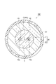
- FIG. 1 is a cross-sectional view of a two-core optical fiber according to a comparative example.
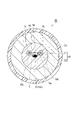
- FIG. 2 is a cross-sectional view of a two-core optical fiber according to the first embodiment.
- FIG. 3 is a diagram showing a side observation image and brightness distribution of the two-core optical fiber according to the first embodiment.
- FIG. 4 is a cross-sectional view of a two-core optical fiber according to the second embodiment.
- FIG. 5 is a cross-sectional view of a two-core optical fiber according to the third embodiment.
- FIG. 6 is a cross-sectional view of a two-core optical fiber according to the fourth embodiment.
- FIG. 7 is a cross-sectional view of a two-core optical fiber according to the fifth embodiment.
- FIG. 8 is a cross-sectional view of a two-core optical fiber according to the sixth embodiment.
- the marker not only complicates the production of the fiber preform, but may also affect the propagation characteristics of the signal propagating through the core.
- the core can be identified by observing the cross section of the fiber, there are cases where it is difficult to observe the cross section of the fiber, such as when the fibers are fused.
- an object of the present disclosure is to provide a multi-core optical fiber and a core identification method capable of identifying cores without using markers and cross-sectional observation.
- a multi-core optical fiber includes a plurality of cores extending along the fiber axis, a plurality of cores, and rotational symmetry with respect to the fiber axis except for a portion where the plurality of cores are provided. and a coating surrounding the cladding and having rotational symmetry with respect to the fiber axis.
- the above multi-core optical fiber has non-inversion symmetry with respect to the fiber axis in a side observation image from at least one of two directions orthogonal to the fiber axis.
- the cores can be identified by the non-inversion symmetry of the side observation image.
- the center of gravity of the plurality of core groups may be separated from the fiber axis in the cross section perpendicular to the fiber axis.
- the "center of gravity of the core group” is also a point having coordinates that are the average values of the positional coordinates of the centers of the cores on the cross section.
- a plurality of cores may have the same shape as each other in a side observation image. Even in this case, the cores can be identified by the non-inversion symmetry based on the arrangement of the cores.
- At least one core among the plurality of cores may have a shape different from that of the other cores in the side observation image.
- the core can be identified by non-inversion symmetry based on the shape of the core.
- the above multi-core optical fiber may have the following configuration. That is, the multi-core optical fiber further includes a low refractive index portion having a lower refractive index than the clad. In a cross section orthogonal to the fiber axis, the low refractive index portion is arranged at a position overlapping the fiber axis.
- the clad has rotational symmetry with respect to the fiber axis, except for the portion where the multiple cores and the low refractive index portion are provided. In this case, crosstalk between signals propagating through two cores sandwiching the low refractive index portion can be suppressed. As a result, it is possible to reduce the inter-core distance required to ensure a certain crosstalk characteristic, so that the connection loss caused by the rotation angle deviation around the fiber axis during fiber connection can be reduced.
- a multi-core optical fiber includes a plurality of cores extending along the fiber axis, and a core centered on the fiber axis and closest to the fiber axis in a cross section orthogonal to the fiber axis.
- a low refractive index portion provided in a circle having a circumference passing through the center and a fiber axis, except for a portion containing a plurality of cores and a low refractive index portion and provided with a plurality of cores and a low refractive index portion and a coating surrounding the cladding and having rotational symmetry about the fiber axis.
- the multi-core optical fiber has non-inversion symmetry with respect to the fiber axis in a side observation image from at least one of two directions perpendicular to the fiber axis.
- the cores can be identified by the non-inversion symmetry of the side observation image.
- the low refractive index portion may have an elliptical shape with a non-circularity of more than 0% and less than or equal to 10%.
- Non-circularity is defined as the difference between the circumscribed and inscribed circle diameters for an object expressed as a percentage of the average diameter.
- the non-circularity may be 6% or more and 10% or less.
- the distance between the core and the low refractive index portion can be further reduced. Thereby, the crosstalk suppression effect can be further enhanced.
- the multiple cores may be two cores.
- a core identification method acquires side observation images from two directions perpendicular to the fiber axis of the multi-core optical fiber, and identifies a plurality of cores based on asymmetry with respect to the fiber axis in the side observation images. .
- the core can be identified by the asymmetry of the side observation image.
- the above two directions may be orthogonal to each other. In this case, the asymmetry of the side observation image can be detected most sharply.
- FIG. 1 is a cross-sectional view of a two-core optical fiber according to a comparative example.
- a two-core optical fiber 100 according to the comparative example includes two cores 10, a clad 20, and a coating 30.
- FIG. 1 is a cross-sectional view of a two-core optical fiber according to a comparative example.
- a two-core optical fiber 100 according to the comparative example includes two cores 10, a clad 20, and a coating 30.
- the two cores 10 extend along the fiber axis C.
- the two cores 10 have the same shape.
- the core 10 has a circular shape in a cross section orthogonal to the fiber axis C (hereinafter also simply referred to as "the cross section").
- a line segment L connecting between the centers 10c of the core 10 passes through the fiber axis C, and the line segment L is bisected by the fiber axis C.
- the fiber axis C forms the midpoint of the line segment L, and the distances from the centers 10c of the two cores 10 to the fiber axis C are equal to each other.
- the core 10 is made of, for example, silica glass containing halogen such as chlorine.
- the glasses forming the two cores 10 have, for example, the same composition.
- the glasses forming the two cores 10 may have different compositions.
- the clad 20 is a common clad that includes (surrounds) the two cores 10 .
- the center 20c of the cladding 20 coincides with the fiber axis C.
- the clad 20 has rotational symmetry with respect to the fiber axis C except for the portion where the two cores 10 are provided.
- the clad 20 has an optical clad 21 and a physical clad 22 .
- the optical clad 21 encloses the two cores 10 and is provided in contact with the outer peripheral surfaces of the two cores 10 .
- the physical clad 22 includes the optical clad 21 and is provided in contact with the outer peripheral surface of the optical clad 21 .
- the optical clad 21 is made of silica glass containing fluorine, for example.
- the refractive index of the optical cladding 21 is lower than that of the core 10 .
- the physical clad 22 is made of silica glass containing fluorine, for example.
- the refractive index of the physical clad 22 is higher than that of the optical clad 21 and lower than that of the core 10 .
- the coating 30 is provided on the outer peripheral surface of the clad 20 .
- the coating 30 includes (surrounds) the clad 20 and is provided in contact with the outer peripheral surface of the clad 20 .
- the coating 30 has rotational symmetry with respect to the fiber axis C;
- the coating 30 is made of resin.
- a urethane acrylate-based UV curable resin can be used as the resin forming the coating 30, for example.
- the two-core optical fiber 100 is not provided with notches or dummy cores that function as markers. Moreover, the two cores 10 have the same shape and are arranged in a rotationally symmetrical position with respect to the fiber axis C in cross section. Therefore, the two cores 10 cannot be distinguished.
- FIG. 2 is a cross-sectional view of a two-core optical fiber according to the first embodiment.
- the 2-core optical fiber 1A according to the first embodiment differs from the 2-core optical fiber 100 in the arrangement of the two cores 10, but is identical in other respects.
- the two-core optical fiber 1 ⁇ /b>A includes two cores 10 having the same shape, a clad 20 including an optical clad 21 and a physical clad 22 , and a coating 30 .
- the cladding 20 has no markers and has rotational symmetry with respect to the fiber axis C except for the portion where the two cores 10 are provided.
- the coating 30 has rotational symmetry with respect to the fiber axis C;
- the outer peripheral surface of the coating 30 is not notched, and the outer peripheral surface of the coating 30 has rotational symmetry with respect to the fiber axis C.
- FIG. 1 has no markers and has rotational symmetry with respect to the fiber axis C except for the portion where the two cores 10 are provided.
- the two cores 10 are arranged at positions shifted parallel to the line segment L so that the distance between the midpoint M of the line segment L and the fiber axis C is ⁇ x in the cross section. . That is, the midpoint M of the line segment L is separated from the fiber axis C (the center 20c of the cladding 20) in a direction parallel to the line segment L by a distance ⁇ x.
- the core identification method includes the steps of acquiring a side-viewing image, evaluating the inversion symmetry of the acquired side-viewing image, and identifying the core 10 using the image.
- the two observation directions are different from each other.
- the two directions are, for example, orthogonal to each other.
- the side observation image is, for example, a transmission image of the two-core optical fiber 1A, and is acquired by irradiating the two-core optical fiber 1A with parallel light parallel to the observation direction.
- FIG. 3 is a diagram showing a side observation image and brightness distribution of the two-core optical fiber according to the first embodiment.
- illustration of the coating 30 (see FIG. 2) is omitted.
- 3 shows side observation images 2 and 3 from two directions perpendicular to the fiber axis C.
- the side observation images 2 and 3 are images obtained by side observation from directions orthogonal to each other.
- the observation direction of the lateral observation image 2 is parallel to the line segment L.
- the observation direction of the lateral observation image 3 is orthogonal to the line segment L. As shown in FIG.
- FIG. 3 also shows the brightness (luminance) distribution corresponding to each of the side observation images 2 and 3.
- the horizontal axis (the axis perpendicular to the viewing direction) indicates the position in the radial direction
- the vertical axis indicates the brightness.
- the horizontal axis is orthogonal to the line segment L.
- the horizontal axis is parallel to the line segment L in the brightness distribution corresponding to the side observation image 3 .
- the brightness of the portion corresponding to the core 10 is higher than the brightness of the portion corresponding to the clad 20 .
- the two cores 10 are observed in a state of overlapping each other. Since the line segment L passes through the fiber axis C, both of the two cores 10 overlap the fiber axis C in the side observation image 2 .
- the two-core optical fiber 1A has inversion symmetry with respect to the fiber axis C in the side observation image 2 .
- the two cores 10 are observed in a state separated from each other. Since the two cores 10 have the same shape, they also have the same shape (same width) in the side observation image 3 and cannot be distinguished from each other by individual shapes. As described above, in the two-core optical fiber 1A, the two cores 10 are arranged at positions shifted parallel to the line segment L. As shown in FIG. Therefore, the two-core optical fiber 1A does not have inversion symmetry with respect to the fiber axis C in the side observation image 3 .
- the two-core optical fiber 1A is rotated 180 degrees about the fiber axis C to invert the side observation image, and the orthogonality (degree of overlap) of the brightness distribution before and after the inversion is evaluated.
- the evaluation of orthogonality is performed, for example, by taking the inner product of the lightness distribution before and after the inversion and based on the obtained inner product.
- the inner product becomes higher as the degree of matching is higher. For example, if the inner product is equal to or greater than a preset threshold, it is determined to be inversion symmetric, and if it is less than the threshold, it is determined to be asymmetric.
- the threshold is set, for example, to 60% of the maximum value of the inner product.
- the inner product has a maximum value for the same brightness distribution.
- the two-core optical fiber 1A has non-inversion symmetry with respect to the fiber axis C in the side observation image 3 from at least one of the two directions orthogonal to the fiber axis C.
- the non-inversion symmetry of the two-core optical fiber 1A in the side observation image 3 is an asymmetry that breaks the inversion symmetry about the fiber axis C.
- the core 10 is identified using the side observation image 3 evaluated as having no inversion symmetry. According to the side observation image 3, two cores 10 that cannot be distinguished from each other can be distinguished.
- the cross-sectional structure has symmetry with respect to mirror image inversion, like the two-core optical fiber 1A shown in FIG. Thereby, the end face structure of the two ends of the optical fiber can be congruent and both ends can have the same connectivity.
- the two-core optical fiber 1A has an asymmetry that breaks the inversion symmetry with respect to the fiber axis C in the side observation image 3 from at least one of the two directions perpendicular to the fiber axis C. is doing. Further, the core identification method acquires side observation images 2 and 3 from two directions perpendicular to the fiber axis C of the two-core optical fiber 1A, and determines the non-inversion symmetry of the two-core optical fiber 1A with respect to the side observation image 3. Two cores 10 are identified based on .
- the multi-core optical fiber fusion device By adding such a core 10 identification function to the multi-core optical fiber fusion device, it becomes possible to identify the core 10 without obtaining a cross-sectional image of the two-core optical fiber 1A. Further, since the two-core optical fiber 1A can be aligned around the fiber axis C, fusion loss between the multi-core optical fibers can be suppressed.
- FIG. 4 is a cross-sectional view of a two-core optical fiber according to the second embodiment.
- the two-core optical fiber 1B according to the second embodiment differs from the two-core optical fiber 100 in the arrangement of the two cores 10, and differs from the two-core optical fiber 100 in other respects.
- the two-core optical fiber 1B includes two cores 10 having the same shape, a clad 20 including an optical clad 21 and a physical clad 22, and a coating 30.
- the clad 20 has rotational symmetry with respect to the fiber axis C except for the portion where the two cores 10 are provided.
- the coating 30 has rotational symmetry with respect to the fiber axis C;
- the two cores 10 are arranged at positions perpendicular to the line segment L so that the distance between the midpoint M of the line segment L and the fiber axis C is ⁇ y in the cross section. . That is, the midpoint M of the line segment L is separated from the fiber axis C (the center 20c of the cladding 20) in the direction perpendicular to the line segment L by a distance ⁇ y.
- the two-core optical fiber 1B does not have non-inversion symmetry with respect to the fiber axis C in the side observation image 3 (see FIG. 3) whose observation direction is orthogonal to the line segment L. Therefore, the two cores 10 cannot be identified only with the side observation image 3 .
- the two-core optical fiber 1B has a non-inverted symmetry with respect to the fiber axis C in the side-viewing image 2 (see FIG. 3) parallel to the viewing direction or line segment L.
- FIG. 2 since the observation direction is parallel to the line segment L, the two cores 10 are observed in a state of overlapping each other. Therefore, the two cores 10 cannot be identified only with the side observation image 2 .
- the two cores 10 are identified using both the side observation images 2 and 3.
- the two-core optical fiber 1B has an asymmetry that breaks the inversion symmetry with respect to the fiber axis C in the side observation image 2 from at least one of the two directions orthogonal to the fiber axis C. is doing.
- the core identification method acquires side observation images 2 and 3 from two directions perpendicular to the fiber axis C of the two-core optical fiber 1B, and determines the non-inversion symmetry of the two-core optical fiber 1B with respect to the side observation image 2. , and the two cores 10 are identified based on the side observation image 3 . Therefore, it can be said that the two cores 10 can be identified by the asymmetry even in the two-core optical fiber 1B and the core identification method.
- FIG. 5 is a cross-sectional view of a two-core optical fiber according to the third embodiment.
- the two-core optical fiber 1C according to the third embodiment has two cores 10 with different core diameters (diameters). It differs from fiber 100 and is otherwise consistent with two-core optical fiber 100 . That is, the two-core optical fiber 1 ⁇ /b>C includes a clad 20 including an optical clad 21 and a physical clad 22 and a coating 30 .
- the clad 20 has rotational symmetry with respect to the fiber axis C except for the portion where the two cores 10 are provided.
- the coating 30 has rotational symmetry with respect to the fiber axis C;
- the core diameter of one core 10 is equivalent to the core diameters of the two cores 10 of the two-core optical fiber 100 .
- the core diameter of the other core 10 is larger than the core diameter of the one core 10 .
- the positions of the centers 10 c of the two cores 10 are the same as the positions of the centers 10 c of the two cores 10 of the two-core optical fiber 100 .
- the shortest distance between one core 10 and the fiber axis C is greater than the shortest distance between the other core 10 and the fiber axis C.
- the two cores 10 are similar to each other.
- the shortest distance between a certain point and the core is defined as the minimum value of the set of distances between all points included in the core and the certain point.
- the two cores 10 have mutually different shapes (different widths).
- the two-core optical fiber 1C does not have inversion symmetry with respect to the fiber axis C in the side observation image 3 . Therefore, in the two-core optical fiber 1 ⁇ /b>C, the core 10 can be identified by the side observation image 3 .
- the side observation image 2 in which the observation direction is parallel to the line segment L, the two cores 10 are observed in a state of overlapping each other. Therefore, the two cores 10 cannot be identified only by the side observation image 2 .
- the two-core optical fiber 1C has an asymmetry that breaks the inversion symmetry with respect to the fiber axis C in the side observation image 3 from at least one of the two directions orthogonal to the fiber axis C. is doing.
- the core identification method acquires side observation images 2 and 3 from two directions orthogonal to the fiber axis C of the two-core optical fiber 1C, and determines the non-inversion symmetry of the two-core optical fiber 1C with respect to the side observation image 3.
- Two cores 10 are identified based on . Therefore, it can be said that the two cores 10 can be identified by the non-inversion symmetry even in the two-core optical fiber 1C and the core identification method.
- FIG. 6 is a cross-sectional view of a two-core optical fiber according to the fourth embodiment.
- a two-core optical fiber 1D according to the fourth embodiment differs from the two-core optical fiber 1B in that it includes a low refractive index portion 40, and is different from the two-core optical fiber 1B in other respects.
- the low refractive index portion 40 is arranged inside the optical clad 21 .
- the low refractive index portion 40 has a refractive index lower than that of the optical clad 21 .
- the low refractive index portion 40 is made of silica glass containing fluorine, for example.
- the diameter of the low refractive index portion 40 is, for example, smaller than the core diameter (diameter) of the core 10 .
- the low refractive index portion 40 is provided between the two cores 10 in cross section. Specifically, the low refractive index portion 40 is arranged so as to overlap the fiber axis C in the cross section.
- the low refractive index portion 40 has a circular cross section and is arranged so that its center overlaps the fiber axis C. As shown in FIG.
- the cladding 20 has rotational symmetry with respect to the fiber axis C except for the portion where the two cores 10 and the low refractive index portion 40 are provided.
- the two-core optical fiber 1D does not have non-inversion symmetry with respect to the fiber axis C in the side observation image 3 (see FIG. 3). It has non-inversion symmetry with respect to the fiber axis C in the directional image 2 (see FIG. 3).
- the side observation image 2 since the observation direction is parallel to the line segment L, the two cores 10 are observed in a state of overlapping each other. Therefore, in the two-core optical fiber 1D, the two cores 10 are identified using both the side observation images 2 and 3.
- the two-core optical fiber 1D has an asymmetry that breaks the inversion symmetry with respect to the fiber axis C in the side observation image 2 from at least one of the two directions perpendicular to the fiber axis C. is doing.
- the core identification method acquires side observation images 2 and 3 from two directions orthogonal to the fiber axis C of the two-core optical fiber 1D, and determines the non-inversion symmetry of the two-core optical fiber 1D with respect to the side observation image 2. , and the two cores 10 are identified based on the side observation image 3 . Therefore, it can be said that the two cores 10 can be identified by the non-inversion symmetry even in the two-core optical fiber 1D and the core identification method.
- the two-core optical fiber 1D has a low refractive index portion 40. Therefore, crosstalk between signals propagating through the two cores 10 sandwiching the low refractive index portion can be suppressed. As a result, it is possible to reduce the inter-core distance required to ensure a certain crosstalk characteristic, so that the connection loss caused by the rotation angle deviation around the fiber axis C during fiber connection can be reduced.
- FIG. 7 is a cross-sectional view of a two-core optical fiber according to the fifth embodiment.
- the 2-core optical fiber 1E according to the fifth embodiment differs from the 2-core optical fiber 1D in the shape of the low refractive index portion 40, and is different from the 2-core optical fiber 1D in other respects.
- the low refractive index portion 40 has an elliptical shape with a non-circularity of more than 0% and less than or equal to 10% in cross section, and is arranged such that its long axis is parallel to the line segment L.
- the length of the long axis of the low refractive index portion 40 is, for example, equivalent to the core diameter of the core 10 .
- the two-core optical fiber 1E also has an asymmetry that breaks the inversion symmetry with respect to the fiber axis C in the side observation image 2 from at least one of the two directions orthogonal to the fiber axis C.
- the core identification method acquires side observation images 2 and 3 from two directions orthogonal to the fiber axis C of the two-core optical fiber 1E, and determines the non-inversion symmetry of the two-core optical fiber 1E with respect to the side observation image 2. , and the two cores 10 are identified based on the side observation image 3 . Therefore, it can be said that the two cores 10 can be identified by the non-inversion symmetry even in the two-core optical fiber 1E and the core identification method.
- the cross-sectional area of the low-refractive-index portion 40 is kept constant, and the core 10 and the low-refractive-index portion are arranged as compared with the case of a perfect circle. It is possible to narrow the distance from the index portion 40 . This can enhance the effect of suppressing crosstalk between signals transmitted through the two cores 10 sandwiching the low refractive index portion.
- the non-circularity may be 6% or more and 10% or less, in which case the crosstalk suppression effect can be further enhanced.
- the manufacturing cost is also suppressed. Also, the influence of the low refractive index portion 40 on the optical characteristics of the two-core optical fiber 1E is suppressed.
- FIG. 8 is a cross-sectional view of a two-core optical fiber according to the sixth embodiment.
- the two-core optical fiber 1F according to the sixth embodiment differs from the two-core optical fiber 100 in that it includes a low refractive index portion 40, and is different from the two-core optical fiber 100 in other respects. Match.
- the low refractive index portion 40 is arranged inside the optical clad 21 .
- the low refractive index portion 40 has a refractive index lower than that of the optical clad 21 .
- the low refractive index portion 40 is made of silica glass containing fluorine, for example.
- the diameter of the low refractive index portion 40 is, for example, shorter than the core diameter (diameter) of the core 10 .
- the low refractive index portion 40 has a circular cross section, but may have an elliptical shape.
- the low refractive index portion 40 may have an elliptical shape with a non-circularity of more than 0% and less than or equal to 10%, and may be arranged so that the long axis is parallel to the line segment L.
- the non-circularity may be 6% or more and 10% or less.
- the low refractive index portion 40 is provided between the two cores 10 in cross section. Specifically, in cross section, the low refractive index portion 40 is provided within a circle centered on the fiber axis C and having a circumference passing through the center of the core 10 closer to the fiber axis C than the two cores 10 . . In the two-core optical fiber 1F, the distances from the two cores 10 to the fiber axis C are equal to each other. A circle is therefore centered on the fiber axis C and passes through the centers 10c of the two cores 10, respectively.
- the low refractive index portion 40 is separated from the fiber axis C in the cross section.
- the low refractive index portion 40 is separated from the fiber axis C in the direction parallel to the line segment L and in the direction orthogonal to the line segment L in the cross section.
- the cladding 20 has rotational symmetry with respect to the fiber axis C except for the portion where the two cores 10 and the low refractive index portion 40 are provided.
- the low refractive index portion 40 is arranged at a position different from the fiber axis C in each of the side observation images 2 and 3 (see FIG. 3).
- the two cores 10 are arranged in inversely symmetrical positions with respect to the fiber axis C
- the two-core optical fiber 1F is aligned with the fiber axis C in each of the side observation images 2 and 3. has non-inversion symmetry. That is, in the two-core optical fiber 1F, the side observation images 2 and 3 can be made different from each other and the two cores 10 can be identified without arranging the two cores 10 at non-inversion symmetrical positions. .
- the two-core optical fiber 1F has an asymmetry that breaks the inversion symmetry with respect to the fiber axis C in the side observation images 2 and 3 from two directions perpendicular to the fiber axis C. .
- the core identification method acquires side observation images 2 and 3 from two directions orthogonal to the fiber axis C of the two-core optical fiber 1F, and non-inverting the two-core optical fiber 1F with respect to the side observation images 2 and 3.
- Two cores 10 are identified based on symmetry. Therefore, it can be said that the two cores 10 can be identified by the non-inversion symmetry even in the two-core optical fiber 1F and the core identification method.
- the midpoint M should be separated from the fiber axis C in at least one of the direction parallel to the line segment L and the direction perpendicular to the line segment L. may be spaced apart from the fiber axis C in each of the directions orthogonal to .
- the two cores 10 are similar to each other, but they do not have to be similar.
- the cross-sectional shape of the other core 10 may be other than circular.
Landscapes
- Physics & Mathematics (AREA)
- General Physics & Mathematics (AREA)
- Optics & Photonics (AREA)
- Mechanical Coupling Of Light Guides (AREA)
Abstract
Description
特許文献1に記載の発明では、マーカがファイバ母材製造を複雑化させるのみならず、コアを伝搬する信号の伝搬特性に影響を及ぼす可能性がある。特許文献2に記載の発明では、ファイバの断面観察によってコアを識別することができるものの、例えば、ファイバ融着時のようにファイバの断面観察が困難な場合もある。
本開示によれば、マーカ及び断面観察によらずコアを識別可能なマルチコア光ファイバ及びコア識別方法が提供される。
最初に本開示の実施態様を列記して説明する。一実施形態に係るマルチコア光ファイバは、ファイバ軸に沿って延在する複数のコアと、複数のコアを内包すると共に、複数のコアが設けられた部分を除き、ファイバ軸に対して回転対称性を有するクラッドと、クラッドを包囲すると共に、ファイバ軸に対して回転対称性を有する被覆と、を備える。上記マルチコア光ファイバは、ファイバ軸に直交する二方向のうち少なくとも一方向からの側方観察像において、ファイバ軸に関して非反転対称性を有している。
本開示のマルチコア光ファイバの具体例を、以下に図面を参照しつつ説明する。なお、本発明はこれらの例示に限定されるものではなく、請求の範囲によって示され、請求の範囲と均等の意味及び範囲内でのすべての変更が含まれることが意図される。図面の説明において同一の要素には同一の符号を付し、重複する説明を省略する。
2,3…側方観察像
10…コア
10c…中心
20…クラッド
20c…中心
21…光学クラッド
22…物理クラッド
30…被覆
40…低屈折率部
C…ファイバ軸
L…線分
M…中間点
Claims (11)
- ファイバ軸に沿って延在する複数のコアと、
前記複数のコアを内包すると共に、前記複数のコアが設けられた部分を除き、前記ファイバ軸に対して回転対称性を有するクラッドと、
前記クラッドを包囲すると共に、前記ファイバ軸に対して回転対称性を有する被覆と、を備え、
前記ファイバ軸に直交する二方向のうち少なくとも一方向からの側方観察像において、前記ファイバ軸に関して非反転対称性を有している、
マルチコア光ファイバ。 - 前記ファイバ軸に直交する断面において、前記複数のコア群の重心は、前記ファイバ軸から離間している、
請求項1に記載のマルチコア光ファイバ。 - 前記複数のコアは、前記側方観察像において互いに同じ形状を有している、
請求項1または請求項2に記載のマルチコア光ファイバ。 - 前記複数のコアのうち少なくとも1つのコアは、前記側方観察像において他のコアと互いに異なる形状を有している、
請求項1または請求項2に記載のマルチコア光ファイバ。 - 前記クラッドの屈折率よりも低い屈折率を有する低屈折率部を更に備え、
前記ファイバ軸に直交する断面において、前記低屈折率部は、前記ファイバ軸と重なる位置に配置され、
前記クラッドは、前記複数のコア及び前記低屈折率部が設けられた部分を除き、前記ファイバ軸に対して回転対称性を有している、
請求項1から請求項4のいずれか1項に記載のマルチコア光ファイバ。 - ファイバ軸に沿って延在する複数のコアと、
前記ファイバ軸に直交する断面において、前記ファイバ軸を中心とし、前記複数のコアのうち前記ファイバ軸に最も近いコアの中心を通る円周を有する円内に設けられた低屈折率部と、
前記複数のコア及び前記低屈折率部を内包すると共に、前記複数のコア及び前記低屈折率部が設けられた部分を除き、前記ファイバ軸に対して回転対称性を有するクラッドと、
前記クラッドを包囲すると共に、前記ファイバ軸に対して回転対称性を有する被覆と、を備えるマルチコア光ファイバであって、
前記ファイバ軸に直交する二方向のうち少なくとも一方向からの側方観察像において、前記ファイバ軸に関して非反転対称性を有している、
マルチコア光ファイバ。 - 前記ファイバ軸に直交する断面において、前記低屈折率部は、非円率が0%よりも高く10%以下である楕円形状を有している、
請求項5または請求項6に記載のマルチコア光ファイバ。 - 前記非円率は、6%以上10%以下である、
請求項7に記載のマルチコア光ファイバ。 - 前記複数のコアは二本のコアである、
請求項1から請求項8のいずれか1項に記載のマルチコア光ファイバ。 - 請求項1から請求項9のいずれか1項に記載のマルチコア光ファイバのファイバ軸に直交する二方向からの側方観察像を取得し、前記側方観察像における前記ファイバ軸に関する非反転対称性に基づき前記複数のコアを識別する、コア識別方法。
- 前記二方向は、互いに直交している、請求項10に記載のコア識別方法。
Priority Applications (4)
| Application Number | Priority Date | Filing Date | Title |
|---|---|---|---|
| US18/552,470 US20240176063A1 (en) | 2021-04-01 | 2022-03-29 | Multi-core optical fiber and core identification method |
| EP22780997.7A EP4318059A4 (en) | 2021-04-01 | 2022-03-29 | MULTI-CORE OPTICAL FIBER AND METHODS FOR CORE DISCRIMINATION |
| JP2023511426A JPWO2022210786A1 (ja) | 2021-04-01 | 2022-03-29 | |
| CN202280019751.0A CN116964499A (zh) | 2021-04-01 | 2022-03-29 | 多芯光纤及纤芯识别方法 |
Applications Claiming Priority (2)
| Application Number | Priority Date | Filing Date | Title |
|---|---|---|---|
| JP2021-063042 | 2021-04-01 | ||
| JP2021063042 | 2021-04-01 |
Publications (1)
| Publication Number | Publication Date |
|---|---|
| WO2022210786A1 true WO2022210786A1 (ja) | 2022-10-06 |
Family
ID=83459516
Family Applications (1)
| Application Number | Title | Priority Date | Filing Date |
|---|---|---|---|
| PCT/JP2022/015694 Ceased WO2022210786A1 (ja) | 2021-04-01 | 2022-03-29 | マルチコア光ファイバ及びコア識別方法 |
Country Status (5)
| Country | Link |
|---|---|
| US (1) | US20240176063A1 (ja) |
| EP (1) | EP4318059A4 (ja) |
| JP (1) | JPWO2022210786A1 (ja) |
| CN (1) | CN116964499A (ja) |
| WO (1) | WO2022210786A1 (ja) |
Cited By (5)
| Publication number | Priority date | Publication date | Assignee | Title |
|---|---|---|---|---|
| WO2023182227A1 (ja) * | 2022-03-24 | 2023-09-28 | 住友電気工業株式会社 | マルチコア光ファイバ |
| WO2024203301A1 (ja) * | 2023-03-28 | 2024-10-03 | 住友電気工業株式会社 | コア位置測定方法およびコア位置測定装置 |
| WO2025105406A1 (ja) * | 2023-11-17 | 2025-05-22 | 古河電気工業株式会社 | マルチコアファイバ |
| WO2025249168A1 (ja) * | 2024-05-29 | 2025-12-04 | 住友電気工業株式会社 | マルチコア光ファイバおよびマルチコア光ファイバ母材 |
| WO2025263438A1 (ja) * | 2024-06-17 | 2025-12-26 | 住友電気工業株式会社 | 光ファイバ、光ファイバ平型素線、光ファイバテープ心線、および、光ファイバテープ心線の製造方法 |
Citations (6)
| Publication number | Priority date | Publication date | Assignee | Title |
|---|---|---|---|---|
| JP2013050695A (ja) * | 2011-08-01 | 2013-03-14 | Furukawa Electric Co Ltd:The | マルチコアファイバの接続方法、マルチコアファイバ、マルチコアファイバの製造方法 |
| US20150043878A1 (en) * | 2013-08-06 | 2015-02-12 | Verizon Patent And Licensing Inc. | Alignment for splicing multi-core optical fibers |
| JP2015099211A (ja) * | 2013-11-18 | 2015-05-28 | 株式会社フジクラ | マルチコアファイバ |
| WO2016084465A1 (ja) * | 2014-11-27 | 2016-06-02 | 古河電気工業株式会社 | 光ファイバ、光ファイバの調芯方法およびその接続構造、テープ心線およびその製造方法 |
| JP2016151716A (ja) * | 2015-02-18 | 2016-08-22 | 株式会社フジクラ | マルチコアファイバ及び光ケーブル |
| JP2021063042A (ja) | 2019-10-16 | 2021-04-22 | 株式会社日本触媒 | タンパク質安定化剤、医薬製剤及び洗浄剤 |
Family Cites Families (11)
| Publication number | Priority date | Publication date | Assignee | Title |
|---|---|---|---|---|
| JP5347989B2 (ja) * | 2010-01-21 | 2013-11-20 | 住友電気工業株式会社 | マルチコア光ファイバ |
| EP2722943A4 (en) * | 2011-06-16 | 2014-11-05 | Furukawa Electric Co Ltd | OPTICAL FIBER WITH MULTIC UR AMPLIFICATION |
| JPWO2014080953A1 (ja) * | 2012-11-26 | 2017-01-05 | 住友電気工業株式会社 | 光導波路、光ファイバケーブル、および光モジュール |
| JP6421822B2 (ja) * | 2014-08-22 | 2018-11-14 | 住友電気工業株式会社 | 光ファイバ |
| DK3211464T3 (da) * | 2014-10-22 | 2021-06-14 | Sumitomo Electric Industries | Optisk multikernefiber, optisk kabel og optisk forbinder |
| MX393960B (es) * | 2015-07-31 | 2025-03-19 | Corning Optical Communications LLC | Cinta de fibra optica enrollable. |
| US10386593B2 (en) * | 2017-05-31 | 2019-08-20 | Corning Research & Development Corporation | Strain sensing optical cable with low vibration attenuation construction |
| WO2020112441A1 (en) * | 2018-11-29 | 2020-06-04 | Corning Research & Development Corporation | Optical fiber cable with laser welded jacket and method of manufacturing |
| US12360309B2 (en) * | 2020-10-09 | 2025-07-15 | Sumitomo Electric Industries, Ltd. | Multi-core optical fiber and multi-core optical fiber cable |
| JP7528703B2 (ja) * | 2020-10-09 | 2024-08-06 | 住友電気工業株式会社 | マルチコア光ファイバおよびマルチコア光ファイバケーブル |
| JP7528712B2 (ja) * | 2020-10-16 | 2024-08-06 | 住友電気工業株式会社 | マルチコア光ファイバおよびマルチコア光ファイバケーブル |
-
2022
- 2022-03-29 US US18/552,470 patent/US20240176063A1/en active Pending
- 2022-03-29 CN CN202280019751.0A patent/CN116964499A/zh active Pending
- 2022-03-29 EP EP22780997.7A patent/EP4318059A4/en active Pending
- 2022-03-29 WO PCT/JP2022/015694 patent/WO2022210786A1/ja not_active Ceased
- 2022-03-29 JP JP2023511426A patent/JPWO2022210786A1/ja active Pending
Patent Citations (6)
| Publication number | Priority date | Publication date | Assignee | Title |
|---|---|---|---|---|
| JP2013050695A (ja) * | 2011-08-01 | 2013-03-14 | Furukawa Electric Co Ltd:The | マルチコアファイバの接続方法、マルチコアファイバ、マルチコアファイバの製造方法 |
| US20150043878A1 (en) * | 2013-08-06 | 2015-02-12 | Verizon Patent And Licensing Inc. | Alignment for splicing multi-core optical fibers |
| JP2015099211A (ja) * | 2013-11-18 | 2015-05-28 | 株式会社フジクラ | マルチコアファイバ |
| WO2016084465A1 (ja) * | 2014-11-27 | 2016-06-02 | 古河電気工業株式会社 | 光ファイバ、光ファイバの調芯方法およびその接続構造、テープ心線およびその製造方法 |
| JP2016151716A (ja) * | 2015-02-18 | 2016-08-22 | 株式会社フジクラ | マルチコアファイバ及び光ケーブル |
| JP2021063042A (ja) | 2019-10-16 | 2021-04-22 | 株式会社日本触媒 | タンパク質安定化剤、医薬製剤及び洗浄剤 |
Non-Patent Citations (1)
| Title |
|---|
| See also references of EP4318059A4 |
Cited By (5)
| Publication number | Priority date | Publication date | Assignee | Title |
|---|---|---|---|---|
| WO2023182227A1 (ja) * | 2022-03-24 | 2023-09-28 | 住友電気工業株式会社 | マルチコア光ファイバ |
| WO2024203301A1 (ja) * | 2023-03-28 | 2024-10-03 | 住友電気工業株式会社 | コア位置測定方法およびコア位置測定装置 |
| WO2025105406A1 (ja) * | 2023-11-17 | 2025-05-22 | 古河電気工業株式会社 | マルチコアファイバ |
| WO2025249168A1 (ja) * | 2024-05-29 | 2025-12-04 | 住友電気工業株式会社 | マルチコア光ファイバおよびマルチコア光ファイバ母材 |
| WO2025263438A1 (ja) * | 2024-06-17 | 2025-12-26 | 住友電気工業株式会社 | 光ファイバ、光ファイバ平型素線、光ファイバテープ心線、および、光ファイバテープ心線の製造方法 |
Also Published As
| Publication number | Publication date |
|---|---|
| CN116964499A (zh) | 2023-10-27 |
| US20240176063A1 (en) | 2024-05-30 |
| JPWO2022210786A1 (ja) | 2022-10-06 |
| EP4318059A1 (en) | 2024-02-07 |
| EP4318059A4 (en) | 2024-10-02 |
Similar Documents
| Publication | Publication Date | Title |
|---|---|---|
| WO2022210786A1 (ja) | マルチコア光ファイバ及びコア識別方法 | |
| CN102449515B (zh) | 多芯光纤 | |
| JP5367726B2 (ja) | マルチコア光ファイバ | |
| CN110140070B (zh) | 低弯曲损耗单模光纤 | |
| JP7671397B2 (ja) | ファイバ接続体、光通信システム、光デバイス、及び、ファイバ接続体の製造方法 | |
| JP5782502B2 (ja) | マルチコアファイバ、及び、それを用いたマルチコアファイバの接続方法 | |
| JP5224371B2 (ja) | マルチコア光ファイバ | |
| JP6287179B2 (ja) | マルチコア光ファイバ及びマルチコア光ファイバコネクタの製造方法 | |
| US9477035B2 (en) | Optical device | |
| JP6421822B2 (ja) | 光ファイバ | |
| CN114384626B (zh) | 多芯光纤及多芯光缆 | |
| JP2022066064A (ja) | マルチコア光ファイバおよびマルチコア光ファイバケーブル | |
| CN116368105B (zh) | 多芯光纤 | |
| JP2014197094A (ja) | マルチコア光ファイバ | |
| JP7591667B2 (ja) | マルチコアファイバ、光デバイス、及び、マルチコアファイバの製造方法 | |
| JPWO2022210786A5 (ja) | ||
| CN108496100A (zh) | 光设备 | |
| JP7227255B2 (ja) | ブリッジファイバ、マルチコアファイバユニット、多芯ブリッジファイバ、及び、多芯マルチコアファイバユニット | |
| JP2022063072A (ja) | マルチコア光ファイバおよびマルチコア光ファイバケーブル | |
| CN101558339A (zh) | 光缆、组件及其性能 | |
| JP7594129B2 (ja) | マルチコアファイバ、光デバイス、及びマルチコアファイバ集合体 | |
| JPH1195049A (ja) | マルチコア光ファイバー | |
| CN116783525A (zh) | 保偏光纤及保偏光纤的制造方法 | |
| WO2024257700A1 (ja) | マルチコアファイバ | |
| JPWO2021079788A5 (ja) |
Legal Events
| Date | Code | Title | Description |
|---|---|---|---|
| 121 | Ep: the epo has been informed by wipo that ep was designated in this application |
Ref document number: 22780997 Country of ref document: EP Kind code of ref document: A1 |
|
| WWE | Wipo information: entry into national phase |
Ref document number: 2023511426 Country of ref document: JP |
|
| WWE | Wipo information: entry into national phase |
Ref document number: 202280019751.0 Country of ref document: CN |
|
| WWE | Wipo information: entry into national phase |
Ref document number: 18552470 Country of ref document: US |
|
| WWE | Wipo information: entry into national phase |
Ref document number: 2022780997 Country of ref document: EP |
|
| ENP | Entry into the national phase |
Ref document number: 2022780997 Country of ref document: EP Effective date: 20231102 |
|
| NENP | Non-entry into the national phase |
Ref country code: DE |