WO2022219982A1 - ステアリングホイール - Google Patents
ステアリングホイール Download PDFInfo
- Publication number
- WO2022219982A1 WO2022219982A1 PCT/JP2022/011181 JP2022011181W WO2022219982A1 WO 2022219982 A1 WO2022219982 A1 WO 2022219982A1 JP 2022011181 W JP2022011181 W JP 2022011181W WO 2022219982 A1 WO2022219982 A1 WO 2022219982A1
- Authority
- WO
- WIPO (PCT)
- Prior art keywords
- stopper
- airbag
- steering wheel
- airbag module
- contact portion
- Prior art date
- Legal status (The legal status is an assumption and is not a legal conclusion. Google has not performed a legal analysis and makes no representation as to the accuracy of the status listed.)
- Ceased
Links
Images






Classifications
-
- B—PERFORMING OPERATIONS; TRANSPORTING
- B60—VEHICLES IN GENERAL
- B60R—VEHICLES, VEHICLE FITTINGS, OR VEHICLE PARTS, NOT OTHERWISE PROVIDED FOR
- B60R21/00—Arrangements or fittings on vehicles for protecting or preventing injuries to occupants or pedestrians in case of accidents or other traffic risks
- B60R21/02—Occupant safety arrangements or fittings, e.g. crash pads
- B60R21/16—Inflatable occupant restraints or confinements designed to inflate upon impact or impending impact, e.g. air bags
- B60R21/20—Arrangements for storing inflatable members in their non-use or deflated condition; Arrangement or mounting of air bag modules or components
- B60R21/203—Arrangements for storing inflatable members in their non-use or deflated condition; Arrangement or mounting of air bag modules or components in steering wheels or steering columns
- B60R21/2035—Arrangements for storing inflatable members in their non-use or deflated condition; Arrangement or mounting of air bag modules or components in steering wheels or steering columns using modules containing inflator, bag and cover attachable to the steering wheel as a complete sub-unit
- B60R21/2037—Arrangements for storing inflatable members in their non-use or deflated condition; Arrangement or mounting of air bag modules or components in steering wheels or steering columns using modules containing inflator, bag and cover attachable to the steering wheel as a complete sub-unit the module or a major component thereof being yieldably mounted, e.g. for actuating the horn switch or for protecting the driver in a non-deployment situation
-
- B—PERFORMING OPERATIONS; TRANSPORTING
- B62—LAND VEHICLES FOR TRAVELLING OTHERWISE THAN ON RAILS
- B62D—MOTOR VEHICLES; TRAILERS
- B62D1/00—Steering controls, i.e. means for initiating a change of direction of the vehicle
- B62D1/02—Steering controls, i.e. means for initiating a change of direction of the vehicle vehicle-mounted
- B62D1/04—Hand wheels
- B62D1/10—Hubs; Connecting hubs to steering columns, e.g. adjustable
-
- B—PERFORMING OPERATIONS; TRANSPORTING
- B62—LAND VEHICLES FOR TRAVELLING OTHERWISE THAN ON RAILS
- B62D—MOTOR VEHICLES; TRAILERS
- B62D7/00—Steering linkage; Stub axles or their mountings
- B62D7/22—Arrangements for reducing or eliminating reaction, e.g. vibration, from parts, e.g. wheels, of the steering system
- B62D7/222—Arrangements for reducing or eliminating reaction, e.g. vibration, from parts, e.g. wheels, of the steering system acting on the steering wheel
-
- B—PERFORMING OPERATIONS; TRANSPORTING
- B62—LAND VEHICLES FOR TRAVELLING OTHERWISE THAN ON RAILS
- B62D—MOTOR VEHICLES; TRAILERS
- B62D1/00—Steering controls, i.e. means for initiating a change of direction of the vehicle
- B62D1/02—Steering controls, i.e. means for initiating a change of direction of the vehicle vehicle-mounted
- B62D1/04—Hand wheels
Definitions
- the present invention relates to steering wheels. More specifically, a steering comprising a core metal having a boss configured to be attachable to a steering shaft, and an airbag module having an inflatable and deployable airbag cushion movably provided with respect to the core metal Regarding wheels.
- a steering wheel mounted on a vehicle is known to have a function as a front airbag in case of vehicle emergency.
- a steering shaft is attached to a boss portion of a metal core, and floating units are provided on both left and right sides and on the lower side as viewed from the steering shaft.
- a horn block consisting of an airbag module and a steering pad is movably supported on the metal core by these three floating units.
- the airbag module When the airbag module inflates and deploys when the airbag is activated, the airbag module is supported by the floating unit, but it is assumed that the floating unit will oscillate. On the other hand, it is preferable that the airbag cushion is rigidly supported as a function of supporting it.
- An object of the present invention is to provide a steering wheel capable of suppressing unnecessary swinging of an airbag module when an airbag is activated, thereby ensuring a predetermined deployment performance of the airbag cushion.
- a steering wheel includes a core metal having a boss portion configured to be attachable to a steering shaft, and an airbag having an inflatable and deployable airbag cushion provided movably with respect to the core metal.
- one of the core metal and the airbag module has a stopper
- the other of the core metal and the airbag module has a stopper abutting portion, and the stopper is in the airbag non-operating state.
- the airbag module is configured to contact the stopper contact portion by moving or deforming due to the expansion and deployment of the airbag cushion when the airbag is activated.
- interference (abutment between the stopper and the stopper abutting portion) occurs between the moved or deformed airbag module and the metal core.
- unnecessary rocking of the airbag module with respect to the metal core can be suppressed when the airbag is activated.
- this swinging can be suppressed by effectively using the core metal and the airbag module while ensuring the mobility of the airbag module with respect to the core metal in the non-operating state of the airbag.
- FIG. 1 is a perspective view showing the appearance of a steering wheel according to Embodiment 1.
- FIG. FIG. 2 is an exploded perspective view showing a state in which an airbag module is removed from a metal core of the steering wheel of FIG. 1;
- FIG. 2 is an enlarged perspective view showing a boss portion of a metal core of the steering wheel of FIG. 1;
- FIG. 2 is a perspective view showing the airbag module of the steering wheel of FIG. 1 from the bottom side;
- FIG. 2 is a cross-sectional view taken along line VV of FIG. 1;
- FIG. 4 is a perspective view showing the module cover of the airbag module from above;
- FIG. 4 is a perspective view showing the module cover of the airbag module from below;
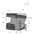
- FIG. 4 is an enlarged perspective view showing the periphery of the stopper of the boss portion from a direction different from that of FIG. 3 ; It is a perspective view which expands and shows the circumference
- FIG. 10 is an enlarged perspective view showing the periphery of the stopper and the stopper abutting portion from a direction different from that of FIG. 9; It is sectional drawing which expands and shows the circumference
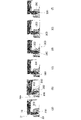
- FIG. 10 is a diagram showing the passage of time when the airbag is activated with respect to the structures of the stopper and the stopper abutting portion; FIG.
- FIG. 4A is a bottom view of the airbag module showing an enlarged periphery of the stopper contacting portion and the reinforcing portion
- FIG. FIG. 2A is a cross-sectional view taken along line BB
- FIG. 4C is a cross-sectional view taken along line CC in FIG.
- FIG. 10A is a bottom view of the airbag module showing the periphery of the stopper contacting portion and the reinforcing portion in an enlarged manner
- FIG. FIG. 2A is a cross-sectional view taken along line BB
- FIG. 4C is a cross-sectional view taken along line CC in FIG.
- FIG. 13A is a bottom view of the airbag module showing the periphery of the stopper contacting portion and the reinforcing portion in an enlarged manner
- FIG. FIG. 2A is a cross-sectional view taken along line BB
- FIG. 4C is a cross-sectional view taken along line CC in FIG.
- FIG. 11 is a side view of the airbag module of the steering wheel according to Embodiment 2, viewed from the negative side in the Y-axis direction
- FIG. 17 is a vertical cross-sectional view of the airbag module of FIG. 16 cut at a position where the stopper and the stopper contacting portion pass through, showing the relationship between the stopper and the stopper contacting portion;
- FIG. 17 is an enlarged cross-sectional view of the airbag module of FIG. 16 cut at a position through which the stopper and the stopper abutting portion pass, showing the relationship between the stopper and the stopper abutting portion;
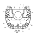
- FIG. 11 is a plan view showing a core metal of a steering wheel according to Embodiment 3;
- FIG. 20 is a diagram showing a situation when the metal core of FIG. 19 is projected onto the bottom view of the airbag module of the steering wheel according to Embodiment 3;
- a steering wheel is placed on the driver's side of a vehicle such as a car, and has multiple functions.
- a steering wheel functions as a vehicle steering device.
- the steering wheel is generally attached to the upper end of a steering shaft provided in the vehicle body in an inclined state.
- a steering force from the driver is transmitted from the steering wheel to the steering shaft, and transmitted to the wheels via the steering gear or the like, thereby changing the direction of the wheels.
- the steering wheel functions as a front airbag in case of vehicle emergency.
- a vehicle emergency is, for example, a time when a vehicle collision occurs.
- the function as a front airbag is mainly achieved by an airbag module installed on the core metal of the steering wheel.
- the steering wheel also functions as a horn device.
- the steering wheel may also act as a dynamic damper to damp vibrations from the vehicle to the steering wheel, such function being achieved using the airbag module as a damper mass.
- the axial direction of the steering shaft is defined as the "Z-axis direction”
- the direction connecting 9 o'clock and 3 o'clock of the analog 12-hour clock on a plane perpendicular to the Z-axis direction is defined as the "X-axis” or “horizontal axis” direction
- the direction connecting 12 o'clock and 6 o'clock on the same clock is the direction of the "Y-axis” or the "vertical axis”.
- the vertical axis and the horizontal axis are orthogonal to each other and orthogonal to the Z-axis direction.
- the direction of the X-axis can be the direction corresponding to the width direction of the steering wheel or vehicle.
- the direction of the Y-axis can be the longitudinal direction of the vehicle (the traveling direction when the vehicle travels straight).
- a plane defined by the X-axis and the Y-axis is called an "XY plane".
- the direction in which the XYZ three-axis arrows point is defined as the "plus side”
- the opposite direction is defined as the "minus side”. Therefore, for example, the plus side of the Y-axis direction is the 12 o'clock side of the analog 12-hour clock, and the minus side of the Y-axis direction is the 6 o'clock side of the clock.
- a steering wheel 1 has a metal core 2 and an airbag module 3 .
- the airbag module 3 is movably provided with respect to the metal core 2 .
- the steering wheel 1 has two types of support units 4a, 4b including spring structures.
- the airbag module 3 is supported by support units 4a and 4b so as to be movable with respect to the metal core 2 along the Z-axis direction. Further, when the airbag is activated, the airbag module 3 is supported by the support units 4a and 4b and swings relative to the core metal 2 in a direction intersecting the Z-axis direction (for example, the XY plane). .
- the core metal 2 forms the skeleton of the steering wheel 1.
- the cored bar 2 is made of, for example, metal such as iron, aluminum, or magnesium.
- the core bar 2 has a boss portion 20 configured to be attachable to a steering shaft 100 (see FIG. 5).
- the core bar 2 has a rim portion 21 that forms the outer periphery of the steering wheel 1 and has spoke portions 22 that connect the boss portion 20 and the rim portion 21 .
- the rim portion 21 is a portion to be gripped by the driver, and is formed in an annular shape here.
- There are a plurality of (here, two) spokes 22 each extending outward from the boss 20 and connected to the rim 21 . In other embodiments, there may be more than two spokes 22 .
- the boss portion 20 includes a shaft attachment portion 23 to which the steering shaft 100 is attached, a base portion 24 having the shaft attachment portion 23 formed in the center in a concave shape, and both ends of the base portion 24 in the X-axis direction.
- Inclined portions 25, 25 which rise obliquely and are connected to the spoke portions 22, and both ends of the base portion 24 in the X-axis direction are connected to each other on the negative side of the base portion 24 in the Y-axis direction at a position away from the shaft mounting portion 23. and a bridge portion 26 .
- a plurality of (here, two) mounting holes 27, 27 are formed through the base portion 24 on both sides in the X-axis direction with the shaft mounting portion 23 interposed therebetween (see FIG. 5). is fitted with a tubular collar 51 .
- the collar 51 has a notch in the middle of a cylindrical portion having a flange portion 53 at one end (see FIG. 5), and a pin 41 of the support unit 4a, which will be described later, is inserted into the cylindrical portion.
- a tab engaging portion 26 a projecting toward the shaft mounting portion 23 is formed in the central portion of the bridge portion 26 .
- a later-described tab 39 of the airbag module 3 is elastically engaged with the tab engaging portion 26a in a detachable state toward the positive side in the Y-axis direction (see FIGS. 1 and 2).
- the boss portion 20 has a base surface 20a on the surface (surface) on the positive side in the Z-axis direction. Most of the base surface 20 a faces the bottom of the airbag module 3 . Further, the base surface 20a has flat spring receiving surfaces 28, 28 at positions on the negative side in the Y-axis direction with respect to the mounting holes 27, 27. As shown in FIG. The spring receiving surface 28 receives one end of the support unit 4b. Protrusions 29 , 29 projecting from the base surface 20 a toward the positive side in the Z-axis direction are formed between the spring receiving surfaces 28 , 28 and the bridge portion 26 . Further, stoppers 200, 200 are formed on the boss portion 20 so as to be connected to the base surface 20a and the convex portion 29 (details will be described later).
- the airbag module 3 has an inflatable and deployable airbag cushion 30 .
- the airbag module 3 includes a housing 31 that houses the airbag cushion 30, an inflator 32 that supplies gas for inflating and deploying the airbag cushion 30 when the airbag is activated, and an airbag. It has a module cover 33 attached to the housing 31 so as to cover the bag cushion 30 and a lock plate 34 attached to the housing 31 .
- the airbag cushion 30 is, for example, folded inside the housing 31 .
- the housing 31 has a bottom wall 36 having a bottom surface along the XY plane and a peripheral wall 37 rising from the bottom wall 36, and is formed in the shape of a shallow dish as a whole.
- the housing 31 is formed by, for example, pressing a single metal plate.
- the inflator 32 is attached to the center of the bottom wall 36, and a plurality of engagement slits 38a, 38b, 38c are formed in the periphery of the bottom wall 36. As shown in FIG. Engagement projections 338a, 338b, and 338c of the module cover 33, which will be described later, are inserted into and engaged with the engagement slits 38a, 38b, and 38c.
- four engaging slits 38a are formed on the positive side in the Y-axis direction, one engaging slit 38b is formed on each side in the X-axis direction, and two engaging slits 38c are formed on the negative side in the Y-axis direction. It is
- a tab 39 having springiness is attached to the housing 31 .
- the tab 39 has a cantilever leaf spring 391 and an insulator 392 provided on the free end side of the leaf spring 391, as shown in FIGS.
- One end of the leaf spring 391 is attached to the surface of the peripheral wall 37 on the negative side in the Y-axis direction, and extends toward the negative side in the Z-axis direction.
- the mounting position of the leaf spring 391 is the center of the airbag module 3 in the X-axis direction.
- the plate spring 391 forms, together with the insulator 392, a receiving opening 394 through which the tab engaging portion 26a of the cored bar 2 is inserted.
- the receiving opening 394 is formed larger than the tab engaging portion 26a, thereby allowing the movement of the airbag module 3 with respect to the core bar 2 (see FIG. 1).
- the end surface (upper surface) of the insulator 392 on the receiving opening 394 side abuts or faces the lower surface of the tab engaging portion 26a.
- the surface on the negative direction side elastically abuts on the root portion of the tab engaging portion 26a (the side surface of the bridge portion 26 of the core metal 2). As a result, the vibration of the cored bar 2 is damped by the elastic action of the plate spring 391 .
- the inflator 32 has a low-profile hollow disc body with gas ejection holes.
- the inflator 32 is activated upon receipt of a signal from the vehicle's sensors to supply gas to the airbag cushion 30 instantaneously. That is, the airbag non-operating state is changed to the airbag operating state.
- the airbag cushion 30 supplied with gas rapidly inflates to rupture the module cover 33, expands toward the driver side of the vehicle interior space, and restrains the driver.
- the lock plate 34 is attached to the bottom wall 36 of the housing 31.
- the lock plate 34 is positioned out of the engagement slits 38a, 38b, 38c.
- the lock plate 34 has a flat portion attached to the bottom wall 36, and has openings 34a, 34a at portions protruding from the flat portion so as to be spaced apart from the bottom wall 36.
- a pin 41 of the support unit 4a is inserted through the pin 34a.
- a fixing plate 32 a for the inflator 32 is also attached to the portion of the lock plate 34 attached to the bottom wall 36 .
- the lock plate 34 is formed by press-molding, for example, one metal plate.
- the lock plate 34 it is possible to omit the lock plate 34 .
- the structure and functions associated with the locking plate 34 are provided in another member of the airbag module 3, for example the housing 31.
- FIG. The bottom of the airbag module 3 facing the core bar 2 is mainly constituted by the lock plate 34 when the lock plate 34 is provided, and is mainly constituted by the bottom wall 36 of the housing 31 when the lock plate 34 is not provided.
- the module cover 33 has a top wall 332 having a top surface 331 along the XY plane and a peripheral wall 333 hanging down from the top wall 332 .
- Top surface 331 is pushed when the driver blows the horn. That is, the module cover 33 functions as a horn switch pressed by the driver when sounding the horn.
- the module cover 33 is open on the side opposite to the top wall 332 , and part of the airbag cushion 30 is accommodated in the space surrounded by the top wall 332 and the peripheral wall 333 .
- the module cover 33 is made of resin, for example.
- the peripheral wall 333 has a plurality of engaging projections 338a, 338b, 338c at the end opposite to the top wall 332.
- the engaging projections 338a, 338b, 338c are respectively engaged with the engaging slits 38a, 38b, 38c of the bottom wall 36 of the housing 31 (see FIGS. 2 and 4). Such engagement attaches the module cover 33 to the housing 31 .
- the engaging protrusions 338a, 338b, and 338c each extend so as to protrude from the peripheral wall 333 to the negative side in the Z-axis direction, and have springiness and a hook shape.
- the engaging protrusion 338c includes a protruding piece 340 having spring properties that protrudes from the peripheral wall 333 to the negative side in the Z-axis direction, an outward hook locking portion 341 formed at the tip of the protruding piece 340, have.
- the hook engaging portion 341 includes an inclined surface 344 that guides the insertion operation when the engaging projection 338c is inserted into the engaging slit 38c, and an opening edge of the engaging slit 38c (on the negative side of the bottom wall 36 in the Z-axis direction). and a locking surface 345 that contacts and locks against the surface).
- the engaging projection 338c extends longer than the other engaging projections 338a, 338b. Specifically, the hook locking portion 341 of the engaging projection 338c extends longer to the negative side in the Z-axis direction than the hook locking portions 341 of the engaging projections 338a and 338b. However, in the engagement protrusions 338a, 338b, and 338c, the positions of the locking surfaces 345 in the Z-axis direction are the same. Of the engaging projections 338a, 338b, and 338c, the engaging projection 338c functions as a stopper contact portion 300 that contacts the stopper 200 of the boss portion 20 (details will be described later).
- the support units 4a, 4b each are plural (here, two each) and are arranged at the bottom of the airbag module 3 .
- the two support units 4a, 4a are arranged on the positive side in the Y-axis direction, and the two support units 4b, 4b are arranged on the negative side in the Y-axis direction, respectively, on both sides in the X-axis direction.
- the support units 4a, 4a are arranged roughly in the directions of 2 o'clock and 10 o'clock, and 4 o'clock. It can also be considered that the support units 4b, 4b are arranged in the 8 o'clock direction.
- the number and locations of the support units 4a and 4b can be set as appropriate.
- the number of support units 4a may be three, arranged at the three o'clock, six o'clock and nine o'clock directions when viewed on an analog 12-hour clock.
- one of the support unit 4a and the support unit 4b may be omitted.
- Various support units are used as long as the support unit can ensure the mobility of the airbag module 3 with respect to the core metal 2 (in particular, movement along the Z-axis direction and swinging in a direction crossing the Z-axis direction). Note that it is possible to As an example, a support unit 4a having a damper function and a support unit 4b having a damper function will be described below.
- the support unit 4a has a pin 41, a spring 42 and a damper assembly 43, and constitutes a module damper that transmits the vibration of the cored bar 2 to the airbag module 3. That is, the support unit 4a functions as a dynamic damper that damps vibrations from the vehicle.
- the damper assembly 43 is attached to the bottom opening 34 a of the airbag module 3 .
- the damper assembly 43 has an elastic body 45 , an inner sleeve 46 and an outer sleeve 47 that hold the elastic body 45 , and an annular piece 48 that covers the upper surface of the elastic body 45 .
- the elastic body 45 is for suppressing the vibration of the steering wheel 1, and is made of rubber, silicon, or the like, and is formed in a ring shape.
- the inner sleeve 46, the outer sleeve 47, and the annular piece 48 are made of resin, for example, and hold the elastic body 45 in the space surrounded by them.
- a pin 41 is inserted inside the inner sleeve 46 .
- the inner sleeve 46 is configured to be slidable in the Z-axis direction with respect to the pin 41 .
- the outer sleeve 47 is attached to the opening 34a. Such attachment secures the support unit 4 a to the bottom of the airbag module 3 . Therefore, when the airbag module 3 moves in the Z-axis direction, the damper assembly 43 also moves in the Z-axis direction together with the airbag module 3. to slide.
- the pin 41 extends in the Z-axis direction and is inserted through the opening 34 a inside the inner sleeve 46 .
- One end of the pin 41 in the Z-axis direction is formed in a flange shape, and the upper part of the damper assembly 43 (the outer edge of the inner sleeve 46, the annular piece 48 and the upper end of the outer sleeve 47) is mounted on the lower side of this flange. is located.
- the other end of the pin 41 in the Z-axis direction is inserted inside the collar 51 and passed through the mounting hole 27 .
- a retaining spring 52 attached to the core metal 2 is retained in the retaining groove 44 at the tip of the pin 41 , thereby fixing the pin 41 to the core metal 2 .
- the spring 42 is a coil spring that surrounds the pin 41 and urges the airbag module 3 away from the core 2 .
- One end of the spring 42 is held by the holding portion 46a of the inner sleeve 46, and the other end is a free end (see FIG. 4).
- the support unit 4b has a bush 61 and a spring 62, as shown in FIG.
- the bush 61 is fixed to the bottom of the airbag module 3 (lock plate 34).
- the spring 62 is a coil spring, one end of which is held by the bushing 61 and the other end of which is free.
- the horn mechanism 70 has a movable contact 71 and a fixed contact 72 .
- the movable contact 71 is provided on the airbag module 3 as shown in FIG.
- two movable contacts 71 are arranged on the flat plate portion of the lock plate 34 .
- the fixed contacts 72 are arranged at two locations on the boss portion 20 of the metal core 2, as shown in FIG. Specifically, the fixed contacts 72, 72 are provided on the top surfaces 29a, 29a of the projections 29, 29, respectively.
- the movable contact 71 and the fixed contact 72 are connected to a horn circuit (not shown) that sounds a horn when energized.
- the movable contact 71 and the fixed contact 72 normally face each other with a gap in the Z-axis direction.
- the airbag module 3 module cover 33
- the airbag module 3 resists the biasing force of the springs 42 and 62 of the support units 4a and 4b.
- the metal core 2 is approached, and the movable contact 71 comes into contact with the fixed contact 72 .
- This contact puts the horn mechanism 70 into a horn operating state and sounds the horn.
- the depression of the airbag module 3 is released, the airbag module 3 is returned to its original position by the urging forces of the springs 42 and 62, and the horn is deactivated.
- a separate or additional horn mechanism 70 may be provided in other embodiments.
- the movable contact 71a of the horn mechanism 70a may be provided on the bottom wall 36 of the housing, and the fixed contact 72a of the horn mechanism 70a may be provided on one end of the pin 41 in the Z-axis direction.
- the airbag module 3 is elastically supported on the core bar 2 mainly by the spring 42 of the support unit 4a and the coil spring 62 of the support unit 4b, and is movable relative to the core bar 2 (especially the Z axis). direction).
- the airbag module 3 is supported by the spring 42 of the support unit 4a and the coil spring 62 of the support unit 4b by the inflated and deployed airbag cushion 30 in the direction intersecting the Z-axis direction. It oscillates with respect to the cored bar 2 .
- the swing suppression structure 400 suppresses unnecessary swing of the airbag module 3 with respect to the metal core 2 toward the positive side in the Y-axis direction so as to prevent such swing.
- the rocking suppression structure 400 includes a stopper 200 that one of the boss portion 20 and the airbag module 3 has, and a stopper abutting portion 300 that the other of the boss portion 20 and the airbag module 3 has.
- the stopper 200 is provided on the boss portion 20 and the stopper contact portion 300 is provided on the module cover 33 of the airbag module 3 .
- the engaging projection 338c of the module cover 33 functions as the stopper contact portion 300. As shown in FIG.
- the stopper 200 is separated from the stopper contact portion 300 in the non-operating state of the airbag.
- the stopper 200 and the stopper contact portion 300 face each other with a gap of about 2 mm, for example.
- the airbag module 3 moves or deforms due to the inflation and deployment of the airbag cushion 30 , so that the stopper 200 contacts the stopper contact portion 300 .
- the stopper 200 is provided on the boss portion 20 so as to extend in the Z-axis direction. Specifically, the stopper 200 rises like a wall from the base surface 20a of the boss portion 20 toward the positive side in the Z-axis direction. Further, the stopper 200 is formed so as to widen slightly from the top surface 201 to the root portion.
- the stopper 200 is formed integrally with the boss portion 20 . For example, when the cored bar 2 is formed by casting, the stopper 200 is formed together with other parts of the boss portion 20 of the cored bar 2 .
- the stopper 200 is connected to the convex portion 29 of the boss portion 20 . Specifically, one end of the stopper 200 is connected to a side portion of the protrusion 29 in the width direction (X-axis direction) orthogonal to both the height direction and the thickness direction. The other widthwise end of the stopper 200 faces the space between the shaft attachment portion 23 and the bridge portion 26 .
- the height (wall height) of the stopper 200 is the same as the height of the projection 29, and the top surface 201 of the stopper 200 and the top surface 29a of the projection 29 are flush with each other.
- the stopper 200 contacts the stopper contact portion 300 in a direction crossing the Z-axis direction when the airbag is activated.
- the stopper 200 contacts the stopper contact portion 300 in the Y-axis direction. Therefore, the stopper 200 has a contact surface 202 that contacts the stopper contact portion 300 on the wall surface on the minus side in the Y-axis direction.
- the stopper 200 is positioned on the negative side in the Y-axis direction when viewed from the shaft mounting portion 23 (steering shaft 100).
- the stopper contact portion 300 (engagement projection 338c) is provided on the module cover 33 so as to extend in the Z-axis direction.
- the stopper contact portion 300 extends so as to protrude from the module cover 33 and faces the stopper 200 on the tip side, and a part (locking surface 345 ) other than the tip side touches the bottom wall 36 of the housing 31 . engaged. Further, the tip of the stopper contact portion 300 is separated from the surface of the boss portion 20 (base surface 20a).
- the stopper contact portion 300 has a contact surface 302 facing the contact surface 202 of the stopper 200 .
- the contact surface 302 is a part of the inner surface (the surface on the positive side in the Y-axis direction) of the stopper contact portion 300, and here, the surface of the hook locking portion 341 located on the opposite side of the inclined surface 344. It's becoming
- the stopper abutting portions 300 can be provided according to the number and arrangement of the stoppers 200 .
- two stopper abutting portions 300 are arranged symmetrically with respect to the Y-axis corresponding to the two stoppers 200 (see FIG. 4).
- FIG. 12 shows the states of the stopper 200 and the stopper contact portion 300 over time when the airbag is activated.
- FIG. 12(a) shows the condition before the airbag is activated (that is, the airbag is not activated), and
- FIGS. (b) shows the situation 3 ms after the start of airbag operation.
- the stopper 200 is separated from the stopper contact portion 300.
- the airbag is operated as shown in FIGS. This is done by deforming or moving the airbag module 3 by the inflated and deployed airbag cushion 30 when the airbag is activated.
- the stopper abutting portion 300 rotates inward about the engagement point (locking surface 345) with the housing 31 (see FIG. 12(b)). Due to such rotation, the tip side of the stopper contact portion 300 (here, the tip side of the contact surface 302 ) contacts the contact surface 202 of the stopper 200 .
- the stopper contact portion 300 is temporarily separated from the stopper 200 by such rocking (see FIG. 12(c)), when the rocking airbag module 3 moves to the positive side in the Y-axis direction, The distal end side of the stopper contact portion 300 (here, the base end side of the contact surface 302) contacts the contact surface 202 of the stopper 200 again (see FIG. 12(d)). Thereafter, while the contact between the stopper contact portion 300 and the stopper 200 is continued, the swinging direction of the airbag module 3 changes to the negative side in the Y-axis direction (see FIGS. 12(e) and 12(f)). )).
- the inflated and deployed airbag cushion 30 first deforms the stopper contacting portion 300 of the airbag module 3 , so that the stopper contacting portion 300 comes into contact with the stopper 200 . Subsequently, although the stopper contact portion 300 is temporarily (instantaneously) separated from the stopper 200 , the stopper contact portion 300 contacts the stopper 200 immediately after that due to the movement of the entire airbag module 3 . .
- the airbag module 3 on the positive side in the Y-axis direction when the airbag is activated. That is, the amount of displacement of the airbag module 3 on the positive side in the Y-axis direction can be suppressed to the initial clearance (about 2 mm) between the stopper contact portion 300 and the stopper 200 .
- the airbag module 3 continues to swing for a predetermined time. For example, after the state shown in FIG. 12(f), the airbag module 3 is displaced to the negative side in the Y-axis direction, and then displaced to the positive side in the Y-axis direction again.
- the stopper contact portion 300 can contact the stopper 200 when displaced to the Y-axis direction plus side again.
- the stopper contact portion 300 contacts the stopper 200 when it is first displaced to the positive side in the Y-axis direction (see FIGS.
- the stopper 200 and the stopper contact portion 300 are Compared to a steering wheel that does not have it, it is possible to delay the timing of starting the displacement to the negative side in the Y-axis direction after that. This leads to stability of initial deployment of the airbag cushion 30 .
- the steering wheel 1 includes a core metal 2 having a boss portion 20 configured to be attachable to a steering shaft 100, and an inflatable and deployable airbag cushion 30 provided movably with respect to the core metal 2.
- one of the metal core 2 and the airbag module 3 has a stopper 200
- the other of the metal core 2 and the airbag module 3 has a stopper contact portion 300 . While the stopper 200 is separated from the stopper abutting portion 300 when the airbag is not in operation, the airbag module 3 is moved or deformed by the expansion and deployment of the airbag cushion 30 when the airbag is in operation. Thereby, it is configured to contact the stopper contact portion 300 .
- interference occurs between the moved or deformed airbag module 3 and the core metal 2 when the airbag is activated.
- unnecessary swinging of the airbag module 3 when the airbag module 3 swings with respect to the metal core 2 when the airbag is activated can be suppressed. Therefore, the predetermined deployment performance of the airbag cushion 30 can be ensured.
- the stopper 200 is provided on the boss portion 20 of the core bar 2 and the stopper contact portion 300 is provided on the airbag module 3 . This makes it possible to effectively use the boss portion 20 and the airbag module 3 to suppress unnecessary swinging of the airbag module 3 .
- the stopper 200 contacts the stopper contact portion 300 in the direction crossing the Z-axis direction (the Y-axis direction in the above example). Therefore, unnecessary swinging of the airbag module 3 in the direction crossing the Z-axis direction is suppressed.
- stoppers 200 there are a plurality of stoppers 200 and they are arranged symmetrically with respect to the Y-axis. As a result, unnecessary swinging of the airbag module 3 can be suppressed in a well-balanced manner when the airbag is activated.
- the stopper 200 rises like a wall from the surface of the boss portion 20 in the Z-axis direction.
- a convex portion 29 that protrudes in the Z-axis direction is formed on the surface of the boss portion 20, and the fixed contact 72 of the horn mechanism 70 is provided on the convex portion 29. At least part of the extending portion is connected to the convex portion 29 .
- the stopper abutment 300 is attached to at least one of the plurality of engaging projections 338a, 338b, 338c (two engaging projections 338c in the above example) that attach the module cover 33 to the housing 32. formed.
- the structure for attaching the module cover 33 to the housing 32 can be effectively used to provide the stopper contact portion 300 on the side of the airbag module 3 .
- stoppers 200 it is possible to change the number of stoppers 200, their arrangement, their abutting directions, and the like. For example, when only one stopper is provided, the stopper may be provided only at the 6 o'clock position of the analog 12-hour clock. Alternatively, the other ends of the two stoppers 200, 200 may be connected to form a single stopper. However, in this case, it goes without saying that the tab 39 must be avoided.
- a stopper may be provided on the positive side in the Y-axis direction when viewed from the steering shaft 100, or may be provided on the positive side in the X-axis direction when viewed from the steering shaft 100. / Or a stopper may be provided on the negative side. Furthermore, three or more stoppers may be provided on one side (for example, the minus side in the Y-axis direction) in the XY orthogonal coordinate system. However, in this case, it is preferable that the plurality of stoppers have a pair of stoppers arranged symmetrically with respect to the X-axis or the Y-axis.
- stopper contact portion 300 may be formed independently of these.
- a stopper contact portion may be provided at a portion that hangs down from the inner surface of the top wall 332 of the module cover 33 .
- the stopper abutting portion 300 may be provided on another member of the airbag module 3 other than the module cover 33 .
- it may be provided on housing 32 or locking plate 34 .
- the stopper abutting portion 300 may have a structure that does not have springiness or does not deform. If the stopper contact portion 300 is not deformed (for example, if it is not rotated as described above), the inflated and deployed airbag cushion 30 moves the entire airbag module 3 when the airbag is activated, thereby contacting the stopper. The portion 300 comes into contact with the stopper 200 .
- a member (buffer material) that absorbs shock is provided at a portion where the stopper 200 and the stopper contact portion 300 contact each other (for example, both or one of the contact surface 202 and the contact surface 302). It may be surface treated for absorption.
- the airbag module 3 has reinforcing portions 510 , 520 , 530 on the side opposite to the stopper 200 when viewed from the stopper contact portion 300 .
- Reinforcing portions 510 , 520 , 530 are configured to prevent deformation of stopper contact portion 300 when stopper 200 contacts stopper contact portion 300 . Prevention of such deformation is particularly effective when the stopper contact portion 300 is formed on the module cover 33 made of a relatively soft material.
- the reinforcing portions 510, 520, 530 can be configured by separate members added to the airbag module 3 (see FIG. 13), or the above members of the airbag module 3 (housing 31 or lock plate 34). ) (see FIGS. 14 and 15).
- the reinforcing portion 510 can be configured with a reinforcing plate attached to the housing 31 .
- Various methods such as screws, rivets, screws, or welding can be used to attach the reinforcing plate. Welding is easy to install here.
- the reinforcing portion 510 is attached to the lower end of the peripheral wall 37 of the housing 31 and extends beyond the bottom wall 36 to the negative side in the Z-axis direction so as to protrude from the bottom wall 36 .
- the reinforcing portion 510 is positioned on the Y-axis direction negative side of the stopper contact portion 300 and faces the straight surface 346 of the hook engaging portion 341 .
- the straight surface 346 is a surface that connects the inclined surface 344 and the locking surface 345 in the hook locking portion 341 .
- the contact between the stopper 200 and the stopper contact portion 300 suppresses unnecessary rocking of the airbag module 3 on the positive side in the Y-axis direction.
- the stopper contact portion 300 is pushed to the negative side in the Y-axis direction by the stopper 200 , but the stopper contact portion 300 contacts the reinforcing portion 510 .
- elastic deformation and/or plastic deformation of the stopper contact portion 300 is prevented.
- FIG. 14 shows an example in which the reinforcing portion 520 is formed on the housing 31.
- the reinforcing portion 520 is formed by cutting and raising a portion of the bottom wall 36 of the housing 31 and extends to the negative side in the Z-axis direction so as to protrude from the bottom wall 36 .
- a part of the engaging slit 38c of the bottom wall 36 is formed so as to be further cut to the negative side in the Y-axis direction, and the cut portion is raised to the negative side in the Z-axis direction to form a reinforcing portion. 520 is formed.
- reinforcing portions 520, 520 are formed at both ends of the engagement slit 38c in the X-axis direction, and the locking surface 345 engages the bottom wall 36 of the housing 31 between the reinforcing portions 520, 520. .
- the reinforcing portion 520 is located on the Y-axis direction negative side of the stopper contact portion 300 and faces at least the straight surface 346 of the hook engaging portion 341 .
- the contact between the stopper 200 and the stopper contact portion 300 suppresses unnecessary rocking of the airbag module 3 on the positive side in the Y-axis direction.
- the stopper contact portion 300 is pushed to the negative side in the Y-axis direction by the stopper 200 , but the stopper contact portion 300 contacts the reinforcing portion 520 .
- elastic deformation and/or plastic deformation of the stopper contact portion 300 is prevented.
- deformation of the stopper contact portion 300 can be prevented by processing the bottom wall 36 of the existing member (housing 31), and a new structure like the reinforcement portion 510 shown in FIG. unnecessary parts.
- FIG. 15 shows an example in which the reinforcing portion 530 is formed on the lock plate 34.
- the reinforcing portion 530 is formed by cutting and raising a portion of the flat portion of the lock plate 34 and extends to the negative side in the Z-axis direction so as to protrude from the lock plate 34 .
- a portion 540 surrounding the stopper abutting portion 300 is formed in the lock plate 34, and a portion on the negative side in the Y-axis direction, which is a part of the portion 540, is provided with a raised portion on the negative side in the Z-axis direction. there is This raised portion serves as the reinforcing portion 530 .
- the reinforcing portion 530 is located on the Y-axis direction negative side of the stopper contact portion 300 and faces the straight surface 346 of the hook engaging portion 341 .
- the contact between the stopper 200 and the stopper contact portion 300 suppresses unnecessary rocking of the airbag module 3 on the positive side in the Y-axis direction.
- the stopper contact portion 300 is pushed to the negative side in the Y-axis direction by the stopper 200 , but the stopper contact portion 300 contacts the reinforcing portion 530 .
- elastic deformation and/or plastic deformation of the stopper contact portion 300 is prevented.
- the reinforcement portion 530 shown in FIG. 15 the deformation of the stopper contact portion 300 can be prevented by processing the flat portion of the existing member (lock plate 34), and a new structure such as the reinforcement portion 510 shown in FIG. unnecessary parts.
- the stopper 1200 and the stopper abutment portion 1300 according to the second embodiment will be described with reference to FIGS. 16 to 18.
- FIG. 1 the stopper 1200 is provided so as to protrude in the Z-axis direction, and the stopper contact portion 1300 is formed as a receiving hole into which the stopper 1200 is loosely fitted.
- the stopper 1200 is configured to come into contact with the inner surface 1301 of the receiving hole.
- the stopper contact portion 1300 is formed on the cored bar 2 . Specifically, the stopper contact portion 1300 is formed to penetrate the spring receiving surface 28 of the cored bar 2 .
- the stopper 1200 is formed as a pin member and provided at the position of the support unit 4b. Specifically, the stopper 1200 extends in the Z-axis direction and is arranged inside the spring 62 of the support unit 4b. One end 1210 of the stopper 1200 in the Z-axis direction is fixed to the bush 61 of the support unit 4b or the bottom of the airbag module 3 (lock plate 34).
- the other end 1220 of the stopper 1200 in the Z-axis direction is inserted into the receiving hole as the stopper contact portion 1300, and is spaced from the inner surface 1310 of the receiving hole with a predetermined clearance in the circumferential direction.
- This clearance can be, for example, the same as the clearance (about 2 mm) between the stopper contact portion 300 and the stopper 200 in the first embodiment.
- interference occurs between the moved airbag module 3 and the core bar 2 when the airbag is activated.
- unnecessary swinging of the airbag module 3 when the airbag module 3 swings with respect to the metal core 2 when the airbag is activated can be suppressed.
- the stopper contact portion 1300 is a hole into which the stopper 1200 is loosely fitted in the circumferential direction, the stopper functions not only in the Y-axis direction but also in many directions including the X-axis direction (all directions crossing the Z-axis direction). can have
- the second embodiment described above is for facilitating understanding of the present invention, and is not for limiting interpretation of the present invention.
- the arrangement of the stopper 200 and the stopper abutting portion 300 (including modifications) in the first embodiment can be applied to the second embodiment. It is also possible to combine the second embodiment and the first embodiment.
- FIG. 3 a stopper 2200 and a stopper abutting portion 2300 according to the third embodiment will be described with reference to FIGS. 19 and 20.
- FIG. 3 the tab 39 and the tab engaging portion 26a are used to form the stopper contact portion 2300 and the stopper 2200. As shown in FIG.
- the airbag module 3 includes a tab 39 having a receiving opening 394 (see FIGS. 1 and 16), and the core bar 2 extends in a direction intersecting the Z-axis direction (here, the Y-axis direction), the tab engaging portion 26a is inserted through the receiving opening 394 from the front side of the tab 39 to the back side of the tab 39.
- the tab engaging portion 26 a has a stopper 2200 at a bent portion facing the rear surface 39 a of the tab 39 .
- the stopper 2200 is configured to contact the rear surface 39a of the tab 39 as the stopper contact portion 2300 when the airbag is activated.
- the tab engaging portion 26a has an engaging portion main body 2600 extending in the Y-axis direction, and a stopper 2200 bending and extending from the tip of the engaging portion main body 2600 in the X-axis direction. ing.
- the engaging portion main body 2600 is connected to the bridge portion 26 on the root side.
- the stopper 2200 is connected to the engaging portion main body 2600 so that the tip thereof is tilted to one side (here, the negative side) in the X-axis direction.
- the engaging portion main body 2600 and the stopper 2200 are configured to be able to be inserted into the receiving opening 394 .
- the tab 39 When inserting, the tab 39 is slightly twisted, and the stopper 2200 is passed through the receiving opening 394 from the front side (negative side in the Y-axis direction) to the back side (positive side in the Y-axis direction) of the tab 39, and then twisted.
- the tab 39 that has been removed is returned to its original shape.
- the stopper 2200 faces the back surface 39a of the plate spring 391 of the tab 39 and is separated.
- interference occurs between the moved airbag module 3 and the core bar 2 when the airbag is activated.
- unnecessary swinging of the airbag module 3 when the airbag module 3 swings with respect to the metal core 2 when the airbag is activated can be suppressed.
- the tab 39 also tries to move to the positive side in the Y-axis direction. It touches and gets caught, and further movement is restricted.
- the third embodiment described above is for facilitating understanding of the present invention, and is not for limiting interpretation of the present invention.
- the configurations (including modifications) such as the arrangement of the stoppers 200, 1200 and the stopper abutting portions 300, 1300 in the first and second embodiments can be applied to the third embodiment.
- Rocking suppression structure 510, 520, 530 Reinforcing portion 540 Part 1200 Stopper 1210 One end 1220 The other end 1300 Stopper contact portion (receiving hole) 1310 Inner surface 2200 Stopper 2300 Stopper contact Contact portion 2600... Engagement portion main body
Landscapes
- Engineering & Computer Science (AREA)
- Mechanical Engineering (AREA)
- Chemical & Material Sciences (AREA)
- Combustion & Propulsion (AREA)
- Transportation (AREA)
- Air Bags (AREA)
- Steering Controls (AREA)
Abstract
Description
図1及び2に示すように、ステアリングホイール1は、芯金2及びエアバッグモジュール3を有している。エアバッグモジュール3は、芯金2に対して可動に設けられている。本実施形態では、ステアリングホイール1は、バネ構造を含む二種類の支持ユニット4a、4bを有している。そして、エアバッグモジュール3は、芯金2に対してZ軸方向に沿って移動可能に支持ユニット4a、4bに支持されている。また、エアバッグモジュール3は、エアバッグ作動時、支持ユニット4a、4bに支持されながら、Z軸方向に交差する方向(例えばXY面)において芯金2に対して揺動するようになっている。
支持ユニット4a、4bは、それぞれ複数(ここでは2つずつ)あり、エアバッグモジュール3の底部に配設されている。2つの支持ユニット4a、4aは、Y軸方向のプラス側において、また、2つの支持ユニット4b、4bは、Y軸方向のマイナス側において、それぞれ、X軸方向の両側に配設されている。別の見方をすれば、エアバッグモジュール3をZ軸方向に直交する平面においてアナログ12時間時計で見た場合、概略、2時及び10時の方向に支持ユニット4a、4aが配置され、4時及び8時の方向に支持ユニット4b、4bが配置されているとみることもできる。
ホーン機構70は、可動接点71及び固定接点72を有している。可動接点71は、図4に示すように、エアバッグモジュール3に設けられている。ここでは、可動接点71は、ロックプレート34の平板部に二か所配置されている。固定接点72は、図3に示すように、芯金2のボス部20に二か所配置されている。詳細には、固定接点72、72は、凸部29、29の頂面29a、29aに設けられている。可動接点71及び固定接点72は、通電時にホーンを鳴らすホーン回路(図示省略)に接続されている。
一方、エアバッグ作動時では、膨張展開したエアバッグクッション30によって、エアバッグモジュール3は、支持ユニット4aのスプリング42及び支持ユニット4bのコイルスプリング62に支持されながら、Z軸方向に交差する方向において芯金2に対して揺動する。本実施形態では、かかる揺動を妨げるように、揺動抑制構造400によって、芯金2に対するエアバッグモジュール3のY軸方向プラス側への不要な揺動を抑制している。
実施形態に係るステアリングホイール1は、ステアリングシャフト100に取付け可能に構成されたボス部20を有する芯金2と、芯金2に対して可動に設けられた、膨張展開可能なエアバッグクッション30を有するエアバッグモジュール3と、を備え、芯金2及びエアバッグモジュール3の一方はストッパ200を有し、芯金2及びエアバッグモジュール3の他方はストッパ当接部300を有している。そして、ストッパ200は、エアバッグ非作動状態において、ストッパ当接部300から離間している一方、エアバッグ作動時において、エアバッグクッション30が膨張展開することによってエアバッグモジュール3が移動又は変形することにより、ストッパ当接部300と当接するように構成されている。
次に、図13~15を参照して、上記実施形態に補強部510、520、530を追加した例について説明する。
次に、図16~18を参照して、実施形態2に係るストッパ1200及びストッパ当接部1300について説明する。実施形態2では、ストッパ1200は、Z軸方向に突出するように設けられ、ストッパ当接部1300は、ストッパ1200が遊嵌される受け穴として形成される。そして、エアバッグ作動時において、ストッパ1200が受け穴の内面1301と当接するように構成されている。
次に、図19及び20を参照して、実施形態3に係るストッパ2200及びストッパ当接部2300について説明する。実施形態3では、タブ39及びタブ係合部26aを利用して、ストッパ当接部2300及びストッパ2200を構成している。
Claims (15)
- ステアリングシャフトに取付け可能に構成されたボス部を有する芯金と、
前記芯金に対して可動に設けられた、膨張展開可能なエアバッグクッションを有するエアバッグモジュールと、を備えたステアリングホイールであって、
前記芯金及び前記エアバッグモジュールの一方はストッパを有し、前記芯金及び前記エアバッグモジュールの他方はストッパ当接部を有しており、
前記ストッパは、
エアバッグ非作動状態において、前記ストッパ当接部から離間している一方、
エアバッグ作動時において、前記エアバッグクッションが膨張展開することによって前記エアバッグモジュールが移動又は変形することにより、前記ストッパ当接部と当接するように構成されている、ステアリングホイール。 - 前記ストッパは、前記芯金の前記ボス部に設けられ、
前記ストッパ当接部は、前記エアバッグモジュールに設けられている、請求項1に記載のステアリングホイール。 - 前記ストッパは、前記ステアリングシャフトの軸方向に交差する方向において、前記ストッパ当接部と当接する、請求項2に記載のステアリングホイール。
- 前記ステアリングシャフトの軸方向に直交し且つ互いに直交する二軸を縦軸及び横軸とした場合、
前記ストッパは、前記縦軸及び横軸の少なくとも一方の方向において、前記ストッパ当接部と当接する、請求項3に記載のステアリングホイール。 - 前記ストッパは、前記ステアリングシャフトの軸方向に延在するように前記ボス部に設けられている、請求項3又は4に記載のステアリングホイール。
- 前記ストッパは、前記ボス部の表面から前記ステアリングシャフトの軸方向に壁状に立ち上がっている、請求項5に記載のステアリングホイール。
- 前記ボス部の表面には、前記ステアリングシャフトの軸方向に突出する凸部が形成されており、
前記ストッパは、前記ステアリングシャフトの軸方向に延在する部位の少なくとも一部が前記凸部に連結されている、請求項5又は6に記載のステアリングホイール。 - 可動接点及び固定接点を有するホーン機構をさらに備え、
前記可動接点は、前記エアバッグモジュールに設けられ、
前記固定接点は、前記凸部の頂面に設けられている、請求項7に記載のステアリングホイール。 - 前記ストッパ当接部は、前記ステアリングシャフトの軸方向に延在するように前記エアバッグモジュールに設けられている、請求項5から8のいずれか一項に記載のステアリングホイール。
- 前記エアバッグモジュールは、前記エアバッグ作動時に前記エアバッグクッションに膨張展開用のガスを供給するインフフレータと、前記エアバッグクッションを収容するハウジングと、前記エアバッグクッションを覆うように前記ハウジングに取り付けられたモジュールカバーと、を有しており、
前記ストッパ当接部は、前記モジュールカバーに設けられている、請求項9に記載のステアリングホイール。 - 前記ストッパ当接部は、前記モジュールカバーから突出するように延びていて、先端側が前記ストッパに対向している共に、当該先端側ではない一部が前記ハウジングに係合しており、
前記エアバッグ作動時において、前記エアバッグクッションの膨張展開による荷重によって前記ストッパ当接部が前記一部を支点として回動することにより、前記ストッパ当接部の前記先端側が前記ストッパに当接する、請求項10に記載のステアリングホイール。 - 前記エアバッグモジュールは、前記ストッパ当接部から見て前記ストッパとは反対側に、前記ストッパが前記ストッパ当接部と当接した際の前記ストッパ当接部の変形を阻止するように構成された補強部をさらに有する、請求項10又は11に記載のステアリングホイール。
- 前記エアバッグモジュールは、前記エアバッグ作動時に前記エアバッグクッションに膨張展開用のガスを供給するインフフレータと、前記エアバッグクッションを収容するハウジングと、前記エアバッグクッションを覆うように前記ハウジングに取り付けられたモジュールカバーと、を有しており、
前記モジュールカバーは、前記ハウジングに係合して当該モジュールカバーを前記ハウジングに取り付ける複数の係合突起を有しており、
前記ストッパ当接部は、前記複数の係合突起の少なくとも一つに形成されている、請求項2から8のいずれか一項に記載のステアリングホイール。 - 前記ストッパは、前記ステアリングシャフトの軸方向に突出するように設けられ、
前記ストッパ当接部は、前記ストッパが遊嵌される受け穴として形成され、
エアバッグ作動時において、前記ストッパが前記受け穴の内面と当接するように構成されている、請求項1に記載のステアリングホイール。 - 前記エアバッグモジュールは、受入れ開口を有するタブを備え、
前記芯金は、前記ステアリングシャフトの軸方向に交差する方向において前記タブの表側から前記タブの裏側へと前記受入れ開口に挿通されたタブ係合部を備え、
前記タブ係合部は、前記タブの裏面に対向する屈曲部位に前記ストッパを有し、
エアバッグ作動時において、前記ストッパは、前記ストッパ当接部としての前記タブの裏面と当接するように構成されている、請求項1に記載のステアリングホイール。
Priority Applications (4)
| Application Number | Priority Date | Filing Date | Title |
|---|---|---|---|
| JP2023514521A JP7531052B2 (ja) | 2021-04-15 | 2022-03-14 | ステアリングホイール |
| CN202280027939.XA CN117157225A (zh) | 2021-04-15 | 2022-03-14 | 方向盘 |
| US18/555,162 US12221051B2 (en) | 2021-04-15 | 2022-03-14 | Steering wheel |
| EP22787908.7A EP4324723A4 (en) | 2021-04-15 | 2022-03-14 | Steering wheel |
Applications Claiming Priority (2)
| Application Number | Priority Date | Filing Date | Title |
|---|---|---|---|
| JP2021069285 | 2021-04-15 | ||
| JP2021-069285 | 2021-04-15 |
Publications (1)
| Publication Number | Publication Date |
|---|---|
| WO2022219982A1 true WO2022219982A1 (ja) | 2022-10-20 |
Family
ID=83640341
Family Applications (1)
| Application Number | Title | Priority Date | Filing Date |
|---|---|---|---|
| PCT/JP2022/011181 Ceased WO2022219982A1 (ja) | 2021-04-15 | 2022-03-14 | ステアリングホイール |
Country Status (5)
| Country | Link |
|---|---|
| US (1) | US12221051B2 (ja) |
| EP (1) | EP4324723A4 (ja) |
| JP (1) | JP7531052B2 (ja) |
| CN (1) | CN117157225A (ja) |
| WO (1) | WO2022219982A1 (ja) |
Citations (5)
| Publication number | Priority date | Publication date | Assignee | Title |
|---|---|---|---|---|
| JPH09254791A (ja) * | 1996-03-21 | 1997-09-30 | Toyoda Gosei Co Ltd | ステアリングホイール |
| JP2011105164A (ja) * | 2009-11-18 | 2011-06-02 | Nippon Plast Co Ltd | エアバッグ装置 |
| JP2012086697A (ja) * | 2010-10-20 | 2012-05-10 | Nippon Plast Co Ltd | エアバッグ装置のカバー体 |
| JP2014094703A (ja) * | 2012-11-12 | 2014-05-22 | Autoliv Development Ab | ステアリングホイールの振動低減構造 |
| WO2015125349A1 (ja) | 2014-02-21 | 2015-08-27 | 本田技研工業株式会社 | ステアリングホイール構造 |
Family Cites Families (7)
| Publication number | Priority date | Publication date | Assignee | Title |
|---|---|---|---|---|
| JP4674409B2 (ja) * | 2001-04-18 | 2011-04-20 | タカタ株式会社 | エアバッグ装置 |
| JP5790311B2 (ja) * | 2011-08-24 | 2015-10-07 | タカタ株式会社 | 運転席用エアバッグ装置の取付構造及びステアリングホイール |
| JP5873408B2 (ja) * | 2012-09-12 | 2016-03-01 | タカタ株式会社 | エアバッグモジュールの取付構造 |
| JP6835633B2 (ja) * | 2017-03-10 | 2021-02-24 | 芦森工業株式会社 | ステアリングハンドル構造 |
| FR3063942B1 (fr) * | 2017-03-14 | 2021-12-10 | Autoliv Dev | Dispositif de commande d’avertisseur sonore de vehicule |
| JP7159075B2 (ja) * | 2019-02-08 | 2022-10-24 | Joyson Safety Systems Japan株式会社 | ステアリングホイール |
| WO2022196134A1 (ja) * | 2021-03-19 | 2022-09-22 | オートリブ ディベロップメント エービー | ステアリングホイール |
-
2022
- 2022-03-14 WO PCT/JP2022/011181 patent/WO2022219982A1/ja not_active Ceased
- 2022-03-14 US US18/555,162 patent/US12221051B2/en active Active
- 2022-03-14 JP JP2023514521A patent/JP7531052B2/ja active Active
- 2022-03-14 CN CN202280027939.XA patent/CN117157225A/zh active Pending
- 2022-03-14 EP EP22787908.7A patent/EP4324723A4/en active Pending
Patent Citations (5)
| Publication number | Priority date | Publication date | Assignee | Title |
|---|---|---|---|---|
| JPH09254791A (ja) * | 1996-03-21 | 1997-09-30 | Toyoda Gosei Co Ltd | ステアリングホイール |
| JP2011105164A (ja) * | 2009-11-18 | 2011-06-02 | Nippon Plast Co Ltd | エアバッグ装置 |
| JP2012086697A (ja) * | 2010-10-20 | 2012-05-10 | Nippon Plast Co Ltd | エアバッグ装置のカバー体 |
| JP2014094703A (ja) * | 2012-11-12 | 2014-05-22 | Autoliv Development Ab | ステアリングホイールの振動低減構造 |
| WO2015125349A1 (ja) | 2014-02-21 | 2015-08-27 | 本田技研工業株式会社 | ステアリングホイール構造 |
Also Published As
| Publication number | Publication date |
|---|---|
| JP7531052B2 (ja) | 2024-08-08 |
| US20240198947A1 (en) | 2024-06-20 |
| JPWO2022219982A1 (ja) | 2022-10-20 |
| EP4324723A4 (en) | 2025-04-23 |
| EP4324723A1 (en) | 2024-02-21 |
| US12221051B2 (en) | 2025-02-11 |
| CN117157225A (zh) | 2023-12-01 |
Similar Documents
| Publication | Publication Date | Title |
|---|---|---|
| KR102610029B1 (ko) | 스티어링 휠 | |
| JP7094763B2 (ja) | ステアリングホイール | |
| US11148702B2 (en) | Damper structure provided in steering wheel of vehicle | |
| US11529921B2 (en) | Steering wheel | |
| JP7159075B2 (ja) | ステアリングホイール | |
| JP2018149837A (ja) | ステアリングハンドル構造 | |
| JP7271728B2 (ja) | 車両のステアリングホイール装置 | |
| US12179683B2 (en) | Steering wheel | |
| CN115135559A (zh) | 方向盘 | |
| JP7531052B2 (ja) | ステアリングホイール | |
| JP4274094B2 (ja) | ステアリングホイール | |
| JP7607778B2 (ja) | ステアリングホイール | |
| JPH0952565A (ja) | ステアリングホイール用ロアカバー | |
| JP2015037913A (ja) | エアバッグ装置 | |
| JP6320005B2 (ja) | エアバッグ装置およびエアバッグ付ステアリングホイール装置 | |
| WO2022158334A1 (ja) | 運転席用エアバッグ装置 | |
| JP2001047957A (ja) | エアバッグ装置 |
Legal Events
| Date | Code | Title | Description |
|---|---|---|---|
| 121 | Ep: the epo has been informed by wipo that ep was designated in this application |
Ref document number: 22787908 Country of ref document: EP Kind code of ref document: A1 |
|
| WWE | Wipo information: entry into national phase |
Ref document number: 2023514521 Country of ref document: JP |
|
| WWE | Wipo information: entry into national phase |
Ref document number: 18555162 Country of ref document: US |
|
| WWE | Wipo information: entry into national phase |
Ref document number: 202317071076 Country of ref document: IN |
|
| WWE | Wipo information: entry into national phase |
Ref document number: 2022787908 Country of ref document: EP |
|
| NENP | Non-entry into the national phase |
Ref country code: DE |
|
| ENP | Entry into the national phase |
Ref document number: 2022787908 Country of ref document: EP Effective date: 20231115 |