WO2022224767A1 - 車両用空調装置 - Google Patents
車両用空調装置 Download PDFInfo
- Publication number
- WO2022224767A1 WO2022224767A1 PCT/JP2022/015875 JP2022015875W WO2022224767A1 WO 2022224767 A1 WO2022224767 A1 WO 2022224767A1 JP 2022015875 W JP2022015875 W JP 2022015875W WO 2022224767 A1 WO2022224767 A1 WO 2022224767A1
- Authority
- WO
- WIPO (PCT)
- Prior art keywords
- air
- cold air
- cold
- outlet
- guide
- Prior art date
- Legal status (The legal status is an assumption and is not a legal conclusion. Google has not performed a legal analysis and makes no representation as to the accuracy of the status listed.)
- Ceased
Links
Images


Classifications
-
- B—PERFORMING OPERATIONS; TRANSPORTING
- B60—VEHICLES IN GENERAL
- B60H—ARRANGEMENTS OF HEATING, COOLING, VENTILATING OR OTHER AIR-TREATING DEVICES SPECIALLY ADAPTED FOR PASSENGER OR GOODS SPACES OF VEHICLES
- B60H1/00—Heating, cooling or ventilating devices
- B60H1/00007—Combined heating, ventilating, or cooling devices
- B60H1/00021—Air flow details of HVAC devices
- B60H1/00064—Air flow details of HVAC devices for sending air streams of different temperatures into the passenger compartment
-
- B—PERFORMING OPERATIONS; TRANSPORTING
- B60—VEHICLES IN GENERAL
- B60H—ARRANGEMENTS OF HEATING, COOLING, VENTILATING OR OTHER AIR-TREATING DEVICES SPECIALLY ADAPTED FOR PASSENGER OR GOODS SPACES OF VEHICLES
- B60H1/00—Heating, cooling or ventilating devices
- B60H1/00007—Combined heating, ventilating, or cooling devices
- B60H1/00021—Air flow details of HVAC devices
- B60H2001/00078—Assembling, manufacturing or layout details
- B60H2001/00092—Assembling, manufacturing or layout details of air deflecting or air directing means inside the device
-
- B—PERFORMING OPERATIONS; TRANSPORTING
- B60—VEHICLES IN GENERAL
- B60H—ARRANGEMENTS OF HEATING, COOLING, VENTILATING OR OTHER AIR-TREATING DEVICES SPECIALLY ADAPTED FOR PASSENGER OR GOODS SPACES OF VEHICLES
- B60H1/00—Heating, cooling or ventilating devices
- B60H1/00007—Combined heating, ventilating, or cooling devices
- B60H1/00021—Air flow details of HVAC devices
- B60H2001/00114—Heating or cooling details
- B60H2001/00135—Deviding walls for separate air flows
-
- B—PERFORMING OPERATIONS; TRANSPORTING
- B60—VEHICLES IN GENERAL
- B60H—ARRANGEMENTS OF HEATING, COOLING, VENTILATING OR OTHER AIR-TREATING DEVICES SPECIALLY ADAPTED FOR PASSENGER OR GOODS SPACES OF VEHICLES
- B60H1/00—Heating, cooling or ventilating devices
- B60H1/00007—Combined heating, ventilating, or cooling devices
- B60H1/00021—Air flow details of HVAC devices
- B60H2001/00185—Distribution of conditionned air
Definitions
- the present invention relates to a vehicle air conditioner that can ensure the linearity of the conditioned air temperature when the air mix door is displaced from the full hot position and can prevent the cool differential phenomenon.
- a vehicle air conditioner includes an air conditioning case in which an air flow path is formed, a cooling heat exchanger disposed inside the air conditioning case for cooling air-conditioning air introduced into the air flow path, and the air conditioning system.
- a heating heat exchanger that heats the conditioned air
- a hot air main passage that passes the conditioned air through the heating heat exchanger and leads it downstream as warm air
- a cold air that bypasses the conditioned air through the heating heat exchanger.
- an air mix door that adjusts the ratio of hot air flowing through the main hot air passage and cold air flowing through the main cold air passage; cold air passing through the main cold air passage and the hot air. and an air mix chamber for mixing hot air that has passed through the main passage to produce conditioned air.
- the air mix chamber there are a defrost outlet for blowing the conditioned air toward the windshield (not shown), a vent outlet for blowing toward the chest of the occupant, and a vent outlet for blowing the air toward the feet of the occupant.
- a foot outlet for blowing out is connected.
- the air conditioning case is provided with a mode door for adjusting the blowing mode by adjusting the amount of conditioned air supplied to the defrost outlet, the vent outlet, and the foot outlet.
- the air mix door has a full hot position that eliminates the cold air flowing through the cold air main passage and passes all the air conditioning air through the warm air main passage, and a full hot position that eliminates the warm air flowing through the warm air main passage and passes all the air conditioning air into the cold air. It is possible to move between the full cool position where it passes through the main passage, especially at the time of a small opening that is slightly displaced from the full hot position to the full cool position side, the air conditioning that has passed through the cooling heat exchanger Air flows into the low-pressure gap (the gap between the air mix door and the seat part where this air mix door seats when it is fully hot), and the air volume exceeds the expected air volume at the minute opening of the air mix door. A phenomenon occurs in which cold air flows out from the main cold air passage into the air mix chamber.
- the linearity of the conditioned air temperature in the air mix room (proportional relationship of the rate of decrease in the temperature of the conditioned air in the air mix room to the amount of movement of the air mix door from the full hot position) is impaired.
- the defrost air outlet connected to the side of the cold air main passage of the cold air main passage reaches the defrost air outlet without being sufficiently mixed with the warm air in the air mix chamber, and a large amount of cold air is sent out from the defrost air outlet. There is concern that a cool differential phenomenon will occur, causing inconveniences such as fogging of the windshield.
- the air mix door is configured by a cantilever door in which a rotation shaft is integrally provided at the end of a flat door body, and the air mix door is rotated at a predetermined rotation angle from the full hot position.
- An arc-shaped guide plate is disclosed that is arranged at a predetermined distance from the tip of the air mix door along the rotation trajectory of the tip of the air mix door over the range. It is thought that the air mix door functions as a cold air amount adjustment guide that limits the amount of cool air flowing into the air mix chamber when the air mix door is in the vicinity of the full hot position.
- the amount of cold air flowing into the air mix chamber when the air mix door is in the vicinity of the full hot position can be suppressed, and the linearity of the conditioned air temperature can be adjusted. In addition, it becomes possible to avoid the cool def phenomenon.
- Patent Document 2 a cold air bypass guide (guide plate) is provided in an air mix chamber to prevent the cold air flowing through the cold air main passage from being mixed with the warm air and guide it to the vent outlet (cold air outlet). Arrangements have been proposed in which fixed guides with According to such a configuration, a required amount of cool air can be positively supplied to the vent outlet without being mixed with warm air, so high temperature control performance can be achieved.
- the air mix door when the air mix door is slightly opened near the full hot position, it is configured to suppress the inflow of cold air from the cold air main passage into the air mix chamber, and the cold air from the cold air main passage is positively directed to the vent outlet. Since the configuration leading to the above requires opposing cold air flows, the problem is how to make these two opposing cold air flows compatible. Such a problem can occur not only when the air mix door is composed of a plate door, but also when it is composed of a sliding door, a rotary door, or the like.
- a main object of the present invention is to provide a vehicular air conditioner capable of achieving both a function of positively guiding cold air from a passageway to a rear air outlet while avoiding mixing with hot air as much as possible.
- a vehicle air conditioner includes: an air conditioning case in which an air flow path is formed; a heating heat exchanger arranged in the air conditioning case for heating the conditioned air introduced into the air flow path; a hot air main flow passage that passes the conditioned air through the heating heat exchanger and guides it downstream as warm air; a cold air main flow passage that bypasses the heat exchanger for heating and guides the conditioned air downstream as cold air; an air mix door for adjusting the ratio of hot air flowing through the hot air main passage and cold air flowing through the cold air main passage; an air mix chamber that mixes the cold air that has passed through the cold air main flow passage and the warm air that has passed through the hot air main flow passage to produce conditioned air; a front outlet connected to the cold air main passage side of the front air mix chamber; a rear outlet connected to a side opposite to the cold air main passage of the air mix chamber; a cold air volume adjustment guide extending from the air conditioning case to the cold air main passage and configured to limit the amount of cold air flowing into
- the cold air introduction port of the cold air bypass guide is faced (opened) to the notch portion of the cold air volume adjustment guide, so that the air mix chamber of cold air. It is possible to achieve a configuration that balances the conflicting effects of the cold air volume adjustment guide that restricts the inflow into the air mix door and the cold air bypass guide that actively guides the cold air to the rear outlet. It is possible to ensure the linearity of the conditioned air temperature at the time of a small displacement from (at the time of a small opening), to reliably prevent the cool differential phenomenon, and to achieve high temperature control performance.
- the cool air bypass guide may be provided on a baffle plate provided in the air mix chamber. That is, the baffle plate guides the hot air from the main hot air passage to the front outlet while blocking mixing with the cold air, and guides the cold air from the main cold air passage to the rear outlet while blocking mixing with the hot air.
- this baffle plate may be substituted for the cold air bypass guide.
- cold air bypass guides may be provided on both sides of the partition wall. Further, when the cold air bypass guide is provided along the side wall of the air conditioning case, the cold air bypass guide may be provided on the side wall of the air conditioning case.
- the cold air bypass guide may guide the cold air to the plurality of rear outlets.
- the cold air bypass guide may be formed in a cylindrical shape, or may be configured by guide plates arranged substantially parallel to each other vertically.
- the above configuration can be applied to various air conditioners, and the front outlet connected to the cold air main passage side of the air mix chamber is at least one of the defrost outlet and the side vent outlet.
- the rear outlet connected to the side opposite to the cold air main passage is at least one of a center vent outlet and a foot outlet.
- the rear outlet may be employed in a vehicle air conditioner that is at least one of a vent outlet and a foot outlet.
- the air mix door extends from the air conditioning case to the cold air main passage and limits the amount of cold air flowing into the air mix chamber when the air mix door is in the vicinity of the full hot position.
- a vehicle air conditioner comprising a cold air volume adjustment guide and a cold air bypass guide for guiding cold air passing through a cold air mainstream passage to a rear outlet while reducing mixing of cold air with warm air from a hot air mainstream passage, wherein the cold air volume is adjusted.
- a part of the guide is notched, and the cold air introduction port of the cold air bypass guide is opened in this notch.
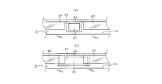
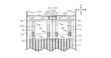
- FIG. 1 is a diagram showing an embodiment of a vehicle air conditioner according to the present invention, (a) is a cross-sectional view showing an example of the overall configuration, and (b) is an air mix door and a cold air amount adjustment guide.
- FIG. 11 is a perspective view of the cold air bypass guide as seen obliquely from the rear;
- FIG. 2 shows an example in which the cold air bypass guide is provided approximately in the center of the air flow path, and the inside of the vehicle air conditioner in FIG. This is a view showing the state where the air mix door has moved below the cold air volume adjustment guide.
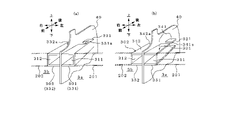
- 3A and 3B are diagrams for explaining another state example in which the notch of the cold air volume adjustment guide and the cold air introduction port of the cold air bypass guide are opened.
- FIG. 11 is a diagram showing an embodiment of a vehicle air conditioner according to the present invention, (a) is a cross-sectional view showing an example of the overall configuration, and (b) is an air mix door and a cold air amount adjustment guide.
- FIG. 10B is a diagram showing an example in which the end of the guide provided with the cold air inlet is smaller than the notch of the cold air volume adjustment guide; FIG. It is a figure which shows the example of.
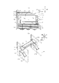
- FIG. 4 is a diagram showing an example in which cold air bypass guides are provided on the left and right sides of the air flow path. is a view of the air mix door side from the top, showing a state in which the air mix door has moved downward from the cold air volume adjustment guide, (b) shows the air mix door, the cold air volume adjustment guide, and the cold air bypass in (a)
- FIG. 10 is a perspective view of the fork guide as seen obliquely from the rear; FIG.
- FIG. 5 is a diagram showing another example in which cold air bypass guides are provided on both left and right sides of the air flow path. It is a view looking at the air mix door side from between, and shows a state where the air mix door has moved downward from the cold air volume adjustment guide, (b) shows the air mix door and the cold air volume adjustment guide in (a)
- FIG. 11 is a perspective view of the cold air bypass guide as seen obliquely from the rear;
- Fig. 6 shows an example in which sliding doors are arranged side by side on the left and right sides of the air flow path, and cold air volume adjustment guides and cold air bypass guides are provided corresponding to the respective sliding doors. It is a figure which shows the example which provided right and left asymmetrically.
- FIG. 11 is a perspective view of the cold air bypass guide as seen obliquely from the rear
- Fig. 6 shows an example in which sliding doors are arranged side by side on the left and right sides of the air flow path, and cold air volume adjustment guides and cold air bypass guides are provided
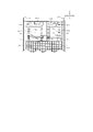
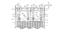
- FIG. 7 is a cross-sectional view showing another embodiment of the vehicle air conditioner according to the present invention, and is a cross-sectional view showing an example in which the downstream side of the evaporator is partitioned left and right by a partition wall.
- FIG. 8 shows an example in which cold air bypass guides are provided on both the left and right sides of the partition wall, and the interior of the vehicle air conditioner in FIG. 7 is viewed from between the cooling heat exchanger and the air mix door.
- FIG. 10 is a diagram showing a state in which the air mix door has moved below the cold air volume adjustment guide.
- FIG. 9 is a perspective view showing a configuration example in which cold wind bypass guides are provided using partition walls in the configuration of FIG. FIG.
- FIG. 8(b) is a diagram showing an example in which the cold air bypass guides are formed by guide plates arranged substantially parallel to each other vertically on both sides of the partition wall.
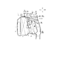
- FIG. 10 is a diagram showing an example in which the cold air bypass guides are provided along the left and right side walls of the air conditioning case.
- FIG. 10 is a side view, showing a state in which the air mix door has moved below the cold air volume adjustment guide.
- FIG. 11 is a perspective view showing a configuration example in which a cold air bypass guide is provided using the side wall of the air conditioning case in the configuration of FIG. (b) is a view showing an example in which the cold air bypass guide is formed by guide plates arranged substantially parallel to each other vertically inside the side wall.
- FIG. 1 shows a vehicle air conditioner 1 mounted near the center console of a vehicle.
- This vehicle air conditioner 1 is arranged closer to the passenger compartment than a partition plate that separates the engine room and the passenger compartment, and outside air (outside air) and/or inside air (air inside the vehicle) is The air is introduced into the air-conditioning case 2 via an air blower unit that does not operate.
- the air-conditioning case 2 forms a passage (air flow path 3) for air flowing toward the passenger compartment, is molded from a synthetic resin material, and flows air through an air inlet 4 on the most upstream side (partition plate side). is provided with an air introduction space 5 for introducing the
- An evaporator 6 forming a cooling heat exchanger is arranged downstream of the air introduction space 5 in the air conditioning case 2, and a heater core 7 forming a heating heat exchanger is arranged downstream of the evaporator 6. .
- the evaporator 6 constitutes a part of the refrigeration cycle, and is erected in the air passage so that all the conditioned air introduced from the air inlet 4 passes through. I am trying to cool it down. Further, the heater core 7 is erected in a lower portion of the air conditioning case 2 located downstream of the evaporator 6 .
- a hot air main passage 8 that passes the conditioned air through a heating heat exchanger 7 and guides it downstream as warm air, and a hot air main passage 8 that bypasses the conditioned air through the heating heat exchanger 7 and serves as cold air.
- a cold air main flow passage 9 leading to the downstream side is provided.
- an air mix door 10 for adjusting the ratio of hot air flowing through the hot air main passage 8 and cold air flowing through the cool air main passage 9 is arranged on the downstream side of the evaporator 6, on the downstream side of the evaporator 6, an air mix door 10 for adjusting the ratio of hot air flowing through the hot air main passage 8 and cold air flowing through the cool air main passage 9 is arranged.
- An air mix chamber 11 is provided above the heater core 7 to mix cold air passing through the cold air main passage 9 and warm air passing through the hot air main passage 8 to produce conditioned air.
- the air mix door 10 is composed of a sliding door, and has door guides 12 extending vertically on the inner surfaces of the left and right side walls of the air conditioning case 2 so as to move up and down along the end face of the evaporator 6 on the ventilation outlet side. , and is slidable along this door guide 12. - ⁇ Specifically, a rack 13 is formed in the vertical direction on the upstream surface of the air mix door 10, a pinion 14 that meshes with the rack 13 is provided on the upstream side of the air mix door 10, and the pinion 14 is moved by an actuator (not shown).
- the full hot position (the position where the hot air main passage 8 is fully opened) that closes the cold air main passage 9 and the full cool position that closes the hot air main passage 8 (the cold air main passage 9 is closed). It is possible to move up and down between the fully open position).
- a front outlet 15 capable of supplying conditioned air toward the window glass or its vicinity.
- a rear outlet 16 is connected to the side of the chamber 11 opposite to the cold air main passage 9 .
- the front air outlet 15 includes a defrost air outlet 151 for blowing conditioned air toward a windshield (not shown) and a side vent air outlet 152 for blowing conditioned air near the side glass. It includes a center vent outlet 161 for blowing conditioned air toward the chest and a foot outlet 162 for blowing conditioned air toward the feet of the occupant.
- the opening of the defrost outlet 151 is adjusted by the defrost door 151a
- the opening of the side vent outlet 152 is adjusted by the side vent door 152a
- the opening of the center vent outlet 161 is adjusted by the center vent door 161a
- the opening of the foot outlet 162 is adjusted by a foot door 162a.
- a cool air volume adjustment guide 20 extending from the air conditioning case 2 is arranged in the cold air main passage 9.
- the cold air amount adjustment guide 20 is formed in a plate shape in this example, and extends from the upper wall of the air conditioning case 2 to the cold air main passage 9 substantially parallel to the locus of movement of the air mix door 10 .
- the cold air amount adjustment guide 20 is arranged at a predetermined distance from the locus of movement of the air mix door so as not to interfere with the vertical movement of the air mix door 10 .
- Such a cold air volume adjustment guide 20 may be arranged upstream or downstream of the air mix door 10. In this example, it is arranged downstream of the air mix door 10. there is also, in this example, the cold air volume adjustment guide 20 is provided over substantially the entire width of the air flow path 3, and the lower edge of the cold air volume adjustment guide is substantially parallel to the upper edge of the air mix door 10. there is
- the cold air volume adjustment guide 20 has the function of limiting the amount of cold air flowing into the air mix chamber 11 when the air mix door 10 is in the vicinity of the full hot position. That is, when the air mix door 10 moves downward from the full hot position located at the top, the upper edge of the air mix door 10 is disengaged from the lower edge of the cold air volume adjustment guide 20 (the upper edge of the air mix door 10 is (located below the lower edge of the cold air volume adjustment guide 20), the amount of cold air flowing into the air mix chamber 11 is restricted. After that, when the upper edge of the air mix door 10 is disengaged from the lower edge of the cold air volume adjustment guide 20, the gap between the air mix door 10 and the cold air volume adjustment guide 20 increases, and more cold air flows into the air mix chamber 11. start.
- a cold air bypass guide 30 is arranged to lead to the center vent outlet 161 and the foot outlet 162).
- the cold air bypass guide 30 is fixed to the air conditioning case 2 by a support (not shown), or is mounted inside the air conditioning case 2 using a fixing portion (not shown) formed integrally with the cold air bypass guide 30, as shown in FIG. As also shown in (b), it is formed as a baffle plate 33 that prevents the cold air from being mixed with the hot air in order to guide it to the rear outlet.
- the cold air bypass guide 30 is formed in a cylindrical shape extending substantially perpendicularly to the cold air volume adjustment guide 20, and has a cold air introduction port 31 which opens toward the cold air volume adjustment guide 20 on one end side. is formed, and a cold air outlet 32 that opens to the rear outlet 16 (center vent outlet 161, foot outlet 162) is formed on the other end side.
- the front side upper surface of the cold air bypass guide is not opened and is faced to the front outlet 15 (defrost outlet 151, side vent outlet 152), and the rear side upper surface and the other end are opened to the rear. It faces the air outlets (center vent air outlet 161 and foot air outlet 162).
- a rectangular notch 21 is provided in the substantially central portion of the cold air volume adjustment guide 20, and the cold air introduction port 31 of the cold air bypass guide 30 is provided in this notch 21. It is designed to open (to face).
- the notch 21 of the cold air volume adjustment guide 20 is provided so as to divide the cold air volume adjustment guide 20 into right and left. Further, even if the end of the cool air introduction port 31 of the cold air bypass guide 30 is fitted into the cutout 21 of the cool air volume adjustment guide 20, it is brought into close contact with the downstream side of the cutout 21, or You may make it open a predetermined space
- the width of the notch 21 of the cold air volume adjustment guide 20 is matched with the width of the end of the cold air bypass guide 30 where the cold air introduction port 31 is formed.
- the width in the vertical direction of the end of the cold air bypass guide 30 where the cold air introduction port 31 is formed is equal to the amount of extension of the cold air amount adjustment guide 20 (the dimension extended downward from the upper surface of the air conditioning case 2). Even if they are matched, the end on the side of the cold air inlet 31 is positioned below the lower edge of the cold air flow adjustment guide 20 so that the required cold air flow to the rear outlet (the air flow that provides the desired temperature control characteristics) can be obtained. may be extended downward.
- the air mix door 10 when the air mix door 10 is in the vicinity of the full hot position (the upper edge of the air mix door 10 is at the same position as the lower edge of the cold air volume adjustment guide 20), , above the lower edge), the amount of cold air flowing into the air mix chamber 11 is restricted, and a narrow gap (predetermined gap) between the air mix door 10 and the cold air amount adjustment guide 20 passes through Since the cold air only flows into the air mix chamber 11 at once, the cold air does not flow into the air mix chamber 11 all at once. ensuring the linearity of the temperature change of the conditioned air). In addition, until the upper edge of the air mix door 10 is removed from the lower edge of the cold air volume adjustment guide 20, the amount of cool air flowing into the air mix chamber is restricted. By opening the notch 21 of the air mix door 10, the inflow pressure of the cold air upstream from the air mix door 10 to the cold air bypass guide 30 is increased, and the cold air flows intensively to the cold air bypass guide 30, and the rear outlet It will lead you to 16.
- the cold air on the upstream side of the air mix door 10 flows from the gap between the air mix door 10 and the cold air volume adjustment guide 20 into the air mix.
- a large amount of air begins to flow toward the chamber 11, but the opening of the air mix door 10 is somewhat large from the full hot position. , and the linearity of the conditioned air temperature is not impaired.
- cold air continues to be supplied to the rear air outlet via the cold air bypass guide 30, so that the amount of cold air led to the air mix chamber 11 is not excessively increased. can be avoided.
- the width of the notch 21 of the cold air volume adjustment guide 20 is matched with the width of the end of the cold air bypass guide 30 where the cold air introduction port 31 is formed. As shown in FIG. 3(a), even if the width of the end on the cold air inlet 31 side is made smaller than the width of the notch 21 of the cold air amount adjustment guide 20, the result shown in FIG. 3(b) is obtained. As shown, the width of the notch 21 of the cold air volume adjustment guide 20 may be larger than that of the notch 21 .
- the width of the end where the cold air introduction port 31 is provided is larger than the width of the notch 21 of the cold air amount adjustment guide 20. is preferably formed to be small.
- the notch 21 of the cold air volume adjustment guide 20 is provided substantially in the center of the air flow path 3 in the horizontal direction, and the cold air introduction port 31 of the cold air bypass guide 30 is opened in this notch 21.
- notches 22 and 23 are provided at both left and right ends of the cold air volume adjustment guide 20, and the notches 22 and 23 at both ends are provided with cold air bypass guides 301 and 302, respectively. may be opened.
- the cold air bypass guides 301 and 302 may be provided with baffle plates on both left and right sides of the air mix chamber 11 as shown in FIG. Cold air bypass guides 301 and 302 having one side removed from the baffle plate shown in FIG. .
- the cool air outlets 321 and 322 are opened to face the rear outlet 16 as in FIG.
- guide plates 341, 342, 351, and 352 are provided on the side walls 2a and 2b of the air conditioning case 2 so as to extend from the side walls 2a and 2b.
- Cold air bypass guides 301 and 302 that are open toward the center of the direction may be formed.
- the guide plates 341, 351, 342, 352 are configured by ribs formed integrally with the side walls 2a, 2b even if separate members are fixed to the side walls 2a, 2b. good too.
- an example in which one air mix door is provided in the air flow path 3 is shown.
- cold air volume adjustment guides 201 and 202 and cold air bypass guides 301 and 302 are provided for each of the air mix doors 101 and 102.
- the cold air volume adjustment guides 201 and 202 and the cold air bypass guides 301 and 302 are arranged in accordance with the air flow unevenness. You may make it provide right-and-left asymmetry.
- the cold air volume adjustment guides 20, 201, and 202 do not maintain a constant extension amount to the cold air main passage 9, but vary the extension amount in the horizontal direction. may
- FIG. 7 and 8 show other configuration examples of the vehicle air conditioner 1.
- FIG. 1 the portion downstream of the evaporator 6 of the air conditioning case 2 is divided into left and right air flow paths 3a and 3b by a partition wall 40, and air mix doors 101 and 102 provided on the left and right.
- the temperature can be controlled independently for the left and right.
- a defrost blower that communicates with the right air flow path 3b and blows conditioned air toward the windshield (not shown) is placed above the cold air main flow path 9 in the air mix chambers 11a and 11b of the air flow paths 3a and 3b.
- a front air outlet 15 consisting of an outlet 153 is provided, and left and right vents for blowing conditioned air toward the chest of the occupant are provided on the opposite side of the cold air main passages 9a and 9b of the air mix chambers 11a and 11b of the air conditioning case 2.
- the rear air outlet 16 is provided with outlets 164 and 165 and left and right foot air outlets 166 and 167 for blowing conditioned air toward the feet of the occupant.
- the opening of defrost outlet 153 is adjusted by defrost door 153a
- the opening of vent outlets 164 and 165 is adjusted by vent doors 164a and 165a
- the opening of foot outlets 166 and 167 is adjusted by foot doors 166a and 167a. is adapted to be regulated by
- cold air volume adjustment guides 201 and 202 and cold air bypass guides 301 and 302 are provided.
- the cold air amount adjustment guides 201 and 202 are provided to extend from the air conditioning case 2 to the cold air main passages 9a and 9b of the left and right air passages 3a and 3b separated by the partition wall 40, and the air mix doors 101 and 102 are fully opened. It has a function of limiting the amount of cold air flowing into the air mix chambers 11a and 11b when they are in the vicinity of the hot position.
- These cold air volume adjustment guides 201 and 202 are formed in a plate shape, for example, and may be arranged upstream or downstream of the air mix door 10, but in this example, the air mix door 10 downstream. Also, in this example, the cold air volume adjustment guides 201 and 202 are provided over substantially the entire width of the air flow paths 3a and 3b between the partition wall 40 and the side walls 2a and 2b of the air conditioning case 2, In addition, the amount of extension from the air conditioning case 2 is substantially uniform (the lower edges of the cold air volume adjustment guides 201 and 202 are substantially parallel to the upper edges of the air mix doors 101 and 102).
- the cold air bypass guides 301 and 302 may be provided using baffle plates as shown in FIG. 1(b). Notches 211 and 212 may be provided between 201 and 202 and the partition wall 40, and the partition wall 40 may be used so that the cold air introduction ports 311 and 312 face the notches 211 and 212. .
- duct forming members 331 and 332 having a U-shaped cross section are fixed to the partition wall 40 on the open side to form a cold air bypass guide.
- 301 and 302 may be cylindrically formed on both sides of the partition wall 40 .
- guide plates 341, 351, 342, 352 arranged substantially parallel to the top and bottom are provided on both side surfaces of the partition wall 40 so as to extend from the partition wall 40.
- the cold air bypass guides 301 and 302 that are open toward the air flow paths 3a and 3b on the air mix chamber side may be formed.
- the guide plates 341 , 351 , 342 , 352 may be formed by fixing separate members to the partition wall 40 or by ribs formed integrally with the partition wall 40 .
- the cold air outlets 321 and 322 face the foot air outlets 166 and 167, and openings 331a and 332a face the vent air outlets 164 and 165 on the upper surface, or , cutouts 341a and 342a are provided to facilitate the introduction of cold air to the rear outlet 16 (vent outlets 164 and 165 and foot outlets 166 and 167).
- cold air amount adjustment guides 201 and 202 and cold air bypass guides 301 and 302 are provided in the respective air flow paths 3a and 3b with the partition wall 40 as a boundary. Cutouts 22 and 23 are provided at the ends of the adjustment guides 201 and 202 on the sides of the side walls 2a and 2b of the air-conditioning case. 302 may be provided using the side walls 2a and 2b of the air conditioning case 2.
- the cold air bypass guides 301 and 302 may be formed in a tubular shape. Further, as shown in FIG. 11(b), guide plates 341, 351, 342, 352 arranged substantially parallel to the top and bottom are provided on the side walls 2a, 2b of the air conditioning case 2 so as to be perpendicular to the side walls. Alternatively, the cold air bypass guides 301 and 302 may be formed so that the air mix chamber side is open.
- the guide plates 341, 351, 342, 352 may be formed by fixing separate members to the side walls 2a, 2b, or may be configured by ribs formed integrally with the side walls 2a, 2b. .
- the amount of cool air blown into the air mix chamber is limited (air mix While adjusting the temperature change amount of the conditioned air with respect to the amount of movement of the door from the full hot position, the cold air can be positively supplied to the rear outlet via the cold air bypass guides 301 and 302, and the conditioned air It is possible to ensure the linearity of the temperature change, avoid the state where cold air is excessively supplied to the front outlet, and achieve high temperature control performance.
- the cold air outlet 32 of the cold air bypass guide 30 is open to both the center vent outlet 161 and the foot outlet 162, but it is not limited to this.
- the side vent outlet 152 and the center vent outlet 161 may be opened, and the foot outlet may not be opened.
- the vehicle air conditioner 1 is in a bi-level mode (a mode in which conditioned air is blown out from the side vent outlet 152, the center vent outlet 161, and the foot outlet 162). is required to be higher than the temperature of the conditioned air blown out from the other air outlets 152 and 161, the cold air guided through the cold air bypass guide 30 is not supplied to the foot air outlet 162. can respond to
- Air Conditioner Air Conditioning Case 2a, 2b Side Wall 3, 3a, 3b Air Flow Path 6 Cooling Heat Exchanger (Evaporator) 7 Heat exchanger for heating (heater core) 8 hot air main passage 9 cold air main passage 10 air mix door 11 air mix chamber 15 front air outlet 16 rear air outlet 20, 201, 202 cold air volume adjustment guide 30, 301, 302 cold air bypass guide 31, 311, 312 cold air introduction mouth 33 baffle plate 40 partition wall 151, 153 defrost outlet 152 side vent outlet 161 center vent outlet 162, 166, 167 foot outlet 164, 165 vent outlet 331, 332 duct forming member 341, 342, 351, 352 guide plate
Landscapes
- Physics & Mathematics (AREA)
- Thermal Sciences (AREA)
- Engineering & Computer Science (AREA)
- Mechanical Engineering (AREA)
- Air-Conditioning For Vehicles (AREA)
Abstract
Description
そして、エアミックス室には、空調用空気を、図示しないフロントガラスへ向けて吹出すためのデフロスト吹出口と、乗員の胸元へ向けて吹出すためのベント吹出口と、乗員の足元へ向けて吹出すためのフット吹出口と、が接続されている。また、空調ケースには、デフロスト吹出口、ベント吹出口、及びフット吹出口に対する調和空気の供給量を調節して吹出モードを調節するモードドアが設けられている。
そこで、このような微小開度時における冷風主流通路からエアミックス室へ供給される冷風量を低減して調和空気温度のリニアリティを調整するために、エアミックスドアがフルホット位置の近傍にあるときの冷風のエアミックス室への流入量を制限する冷風量調整ガイドを設けることが望ましい。
そこで、下記の特許文献2には、エアミックス室に、冷風主流通路を通流する冷風を温風との混合を防止しつつベント吹出口(冷風吹出口)へ導く冷風バイパス用ガイド(ガイドプレートを備えた固定ガイド)を設置する構成が、提案されている。
このような構成によれば、必要量の冷風を温風と混合させることなくベント吹出口へ積極的に供給することができるので、高い温調性能を達成することが可能となる。
このような問題は、エアミックスドアが板ドアで構成される場合のみならず、スライドドアやロータリドア等で構成される場合においても、同様に生じ得る。
内部に空気流路が形成された空調ケースと、
前記空調ケース内に配されて前記空気流路に導入された空調空気を加熱する加熱用熱交換器と、
前記空調空気を前記加熱用熱交換器を通過させて温風として下流側へ導く温風主流通路と、
前記空調空気を前記加熱用熱交換器をバイパスさせて冷風として下流側へ導く冷風主流通路と、
前記温風主流通路を流れる温風と前記冷風主流通路を流れる冷風との割合を調節するエアミックスドアと、
前記冷風主流通路を通過した冷風と前記温風主流通路を通過した温風を混合し調和空気とするエアミックス室と、
前方エアミックス室の前記冷風主流通路寄りに接続される前方吹出口と、
前記エアミックス室の前記冷風主流通路とは反対側に接続される後方吹出口と、
前記空調ケースから前記冷風主流通路に延出して形成され、前記エアミックスドアがフルホット位置の近傍にあるときの前記冷風の前記エアミックス室への流入量を制限する冷風量調整ガイドと、を備えた車両用空調装置において、
前記冷風主流通路を通過した冷風を冷風導入口より取り込んで前記温風主流通路からの温風との混合を低減しつつ前記後方吹出口へ導く冷風バイパス用ガイドを備え、
前記冷風量調整ガイドは、当該ガイドの一部を切り欠いた切り欠きを有し、
前記冷風導入口は、前記切り欠きに臨むことを特徴としている。
すなわち、温風主流通路からの温風を冷風との混合を遮断しつつ前方吹出口へ導き、冷風主流通路からの冷風を温風との混合を遮断しつつ後方吹出口へ導くバッフルプレートをエアミックス室に設ける場合には、冷風バイパス用ガイドをこのバッフルプレートで代用してもよい。
また、冷風バイパス用ガイドを空調ケースの側壁に沿って設ける場合には、冷風バイパス用ガイドを、空調ケースの側壁に設けるようにしてもよい。
また、冷風バイパス用ガイドは、筒状に形成されるものであっても、上下に略平行に配置されたガイド用プレートによって構成されるものであってもよい。
図1において、車両のセンターコンソール部の近傍に搭載される車両用空調装置1が示されている。この車両用空調装置1は、エンジンルームと車室とを区画する仕切板よりも車室側に配されているもので、外気(車室外空気)および/または内気(車室内空気)が、図示しない送風機ユニットを介して空調ケース2内に導入されるようになっている。
ここで、前方吹出口15は、図示しないフロントガラスへ向けて調和空気を吹き出すデフロスト吹出口151や、サイドガラスの近傍に調和空気を吹き出すサイドベント吹出口152を含み、後方吹出口16は、乗員の胸元へ向けて調和空気を吹き出すセンタベント吹出口161や、乗員の足元へ向けて調和空気を吹き出すフット吹出口162を含む。
ここで、冷風量調整ガイド20の切り欠き21は、冷風量調整ガイド20を左右に分断するように設けられている。
また、冷風バイパス用ガイド30の冷風導入口31の端部は、冷風量調整ガイド20の切り欠き21に嵌合させるようにしても、この切り欠き部分21の下流側に密着させて、又は、所定の間隔を開けて対向させるようにしてもよい。
また、エアミックスドア10の上端縁が冷風量調整ガイド20の下端縁から外れるまでは、冷風のエアミックス室への流入量が制限されているので、冷風バイパス用ガイド30を冷風量調整ガイド20の切り欠き21に開口させることで、エアミックスドア10より上流側の冷風の冷風バイパス用ガイド30への流入圧が高められ、冷風はこの冷風バイパス用ガイド30に集中的に流れ、後方吹出口16へ導かれることとなる。
また、この状態においても、冷風バイパス用ガイド30を介して冷風は後部吹出口へ供給され続けるので、結果的にエアミックス室11へ導かれる冷風が過剰に多くなることはなく、また、クールデフ現象を回避することが可能となる。
エアミックスドア10のフルホット位置からの移動量に対する調和空気の温度変化量を調整する観点からは、冷風導入口31が設けられる端部の横幅を冷風量調整ガイド20の切り欠き21の横幅よりも小さく形成することが好ましい。
このような構成において、空気流路3の右側と左側とで空気の流れに偏りが生じる場合、冷風量調整ガイド201,202と冷風バイパス用ガイド301,302は、空気の流れの偏りに併せて左右非対称に設けるようにしてもよい。
また、前述までの実施例においても同様であるが、各冷風量調整ガイド20,201,202は、冷風主流通路9への延出量を一定とせずに、左右方向で延出量を変化させてもよい。
この例では、各空気流路3a,3bのエアミックス室11a,11bの冷風主流通路9寄りの上方に、右側の空気流路3bと連通し図示しないフロントガラスへ向けて空調空気を吹き出すデフロスト吹出口153からなる前方吹出口15が設けられ、また、空調ケース2のエアミックス室11a,11bの冷風主流通路9a,9bと反対側に、乗員の胸元へ向けて空調空気を吹き出す左右のベント吹出口164,165や、乗員の足元へ向けて空調空気を吹き出す左右のフット吹出口166,167からなる後方吹出口16が設けられている。
デフロスト吹出口153の開度は、デフロストドア153aによって調節され、ベント吹出口164,165の開度は、ベントドア164a,165aによって調節され、フット吹出口166,167の開度は、フットドア166a、167aによって調節されるようになっている。
2 空調ケース
2a,2b 側壁
3,3a,3b 空気流路
6 冷却用熱交換器(エバポレータ)
7 加熱用熱交換器(ヒータコア)
8 温風主流通路
9 冷風主流通路
10 エアミックスドア
11 エアミックス室
15 前方吹出口
16 後方吹出口
20,201,202 冷風量調整ガイド
30,301,302 冷風バイパス用ガイド
31,311,312 冷風導入口
33 バッフルプレート
40 仕切壁
151,153 デフロスト吹出口
152 サイドベント吹出口
161 センタベント吹出口
162,166,167 フット吹出口
164,165 ベント吹出口
331,332 ダクト形成用部材
341,342,351,352 ガイド用プレート
Claims (9)
- 内部に空気流路3が形成された空調ケース2と、
前記空調ケース2内に配されて前記空気流路3に導入された空調空気を加熱する加熱用熱交換器7と、
前記空調空気を前記加熱用熱交換器7を通過させて温風として下流側へ導く温風主流通路8と、
前記空調空気を前記加熱用熱交換器8をバイパスさせて冷風として下流側へ導く冷風主流通路9と、
前記温風主流通路8を流れる温風と前記冷風主流通路9を流れる冷風との割合を調節するエアミックスドア10と、
前記冷風主流通路9を通過した冷風と前記温風主流通路8を通過した温風を混合し調和空気とするエアミックス室11と、
前方エアミックス室11の前記冷風主流通路9寄りに接続される前方吹出口15と、
前記エアミックス室11の前記冷風主流通路9とは反対側に接続される後方吹出口16と、
前記空調ケース2から前記冷風主流通路9に延出して形成され、前記エアミックスドア10がフルホット位置の近傍にあるときの前記冷風の前記エアミックス室11への流入量を制限する冷風量調整ガイド20と、を備えた車両用空調装置において、
前記冷風主流通路9を流れる冷風を冷風導入口31より取り込んで前記温風主流通路8を流れる温風との混合を低減しつつ前記後方吹出口16へ導く冷風バイパス用ガイド30を備え、
前記冷風量調整ガイド20は、当該ガイド20の一部を切り欠いた切り欠き21を有し、
前記冷風導入口31は、前記切り欠き21に臨むことを特徴とする車両用空調装置。 - 前記冷風バイパス用ガイド30は、前記エアミックス室11に設けられたバッフルプレート33に設けられていることを特徴とする請求項1記載の車両用空調装置。
- 前記冷風バイパス用ガイド30は、前記空気流路3を左右に仕切る仕切壁40の両側に設けられることを特徴とする請求項1記載の車両用空調装置。
- 前記冷風バイパス用ガイド30は、前記空調ケース2の側壁2a,2bに設けられることを特徴とする請求項1記載の車両用空調装置。
- 前記冷風バイパス用ガイド30は、複数の前記後方吹出口16へ冷風を導くものである請求項1乃至4のいずれかに記載の車両用空調装置。
- 前記冷風バイパス用ガイド30は、筒状に形成されていることを特徴とする請求項1乃至5のいずれかに記載の車両用空調装置。
- 前記冷風バイパス用ガイド30は、上下に略平行に配置されたガイド用プレート341,342,351,352によって構成されることを特徴とする請求項1乃至5のいずれかに記載の車両用空調装置。
- 前記前方吹出口15は、デフロスト吹出口151及びサイドベント吹出口152の少なくとも一方であり、前記後方吹出口16は、センタベント吹出口161及びフット吹出口162の少なくとも一方である請求項1乃至7のいずれかに記載の車両用空調装置。
- 前記前方吹出口15は、デフロスト吹出口153であり、前記後方吹出口16は、ベント吹出口164,165及びフット吹出口166,167の少なくとも一方である請求項1乃至7のいずれかに記載の車両用空調装置。
Priority Applications (3)
| Application Number | Priority Date | Filing Date | Title |
|---|---|---|---|
| EP22791542.8A EP4342696A4 (en) | 2021-04-19 | 2022-03-30 | Vehicle air-conditioning device |
| JP2023516394A JPWO2022224767A1 (ja) | 2021-04-19 | 2022-03-30 | |
| CN202280028978.1A CN117177870A (zh) | 2021-04-19 | 2022-03-30 | 车辆用空调装置 |
Applications Claiming Priority (2)
| Application Number | Priority Date | Filing Date | Title |
|---|---|---|---|
| JP2021-070077 | 2021-04-19 | ||
| JP2021070077 | 2021-04-19 |
Publications (1)
| Publication Number | Publication Date |
|---|---|
| WO2022224767A1 true WO2022224767A1 (ja) | 2022-10-27 |
Family
ID=83722201
Family Applications (1)
| Application Number | Title | Priority Date | Filing Date |
|---|---|---|---|
| PCT/JP2022/015875 Ceased WO2022224767A1 (ja) | 2021-04-19 | 2022-03-30 | 車両用空調装置 |
Country Status (4)
| Country | Link |
|---|---|
| EP (1) | EP4342696A4 (ja) |
| JP (1) | JPWO2022224767A1 (ja) |
| CN (1) | CN117177870A (ja) |
| WO (1) | WO2022224767A1 (ja) |
Families Citing this family (1)
| Publication number | Priority date | Publication date | Assignee | Title |
|---|---|---|---|---|
| WO2025258965A1 (ko) * | 2024-06-11 | 2025-12-18 | 한온시스템 주식회사 | 차량용 공조장치 |
Citations (3)
| Publication number | Priority date | Publication date | Assignee | Title |
|---|---|---|---|---|
| JPH07251629A (ja) * | 1994-03-15 | 1995-10-03 | Nippondenso Co Ltd | 自動車用空調装置 |
| JP2009143330A (ja) | 2007-12-12 | 2009-07-02 | Calsonic Kansei Corp | 自動車用空気調和装置 |
| JP2017013732A (ja) * | 2015-07-06 | 2017-01-19 | カルソニックカンセイ株式会社 | 車両用空調装置 |
Family Cites Families (4)
| Publication number | Priority date | Publication date | Assignee | Title |
|---|---|---|---|---|
| FR2740398B1 (fr) * | 1995-10-26 | 1997-12-12 | Valeo Climatisation | Dispositif de chauffage-ventilation de l'habitacle d'un vehicule automobile |
| JP4388243B2 (ja) * | 2001-06-27 | 2009-12-24 | 三菱重工業株式会社 | 車両用空調装置 |
| JP4172013B2 (ja) * | 2003-02-10 | 2008-10-29 | 株式会社ヴァレオサーマルシステムズ | 自動車用空調装置 |
| JP2009202687A (ja) * | 2008-02-27 | 2009-09-10 | Denso Corp | 車両用空調装置 |
-
2022
- 2022-03-30 JP JP2023516394A patent/JPWO2022224767A1/ja active Pending
- 2022-03-30 CN CN202280028978.1A patent/CN117177870A/zh active Pending
- 2022-03-30 EP EP22791542.8A patent/EP4342696A4/en active Pending
- 2022-03-30 WO PCT/JP2022/015875 patent/WO2022224767A1/ja not_active Ceased
Patent Citations (3)
| Publication number | Priority date | Publication date | Assignee | Title |
|---|---|---|---|---|
| JPH07251629A (ja) * | 1994-03-15 | 1995-10-03 | Nippondenso Co Ltd | 自動車用空調装置 |
| JP2009143330A (ja) | 2007-12-12 | 2009-07-02 | Calsonic Kansei Corp | 自動車用空気調和装置 |
| JP2017013732A (ja) * | 2015-07-06 | 2017-01-19 | カルソニックカンセイ株式会社 | 車両用空調装置 |
Non-Patent Citations (1)
| Title |
|---|
| See also references of EP4342696A4 |
Also Published As
| Publication number | Publication date |
|---|---|
| EP4342696A4 (en) | 2025-06-18 |
| CN117177870A (zh) | 2023-12-05 |
| EP4342696A1 (en) | 2024-03-27 |
| JPWO2022224767A1 (ja) | 2022-10-27 |
Similar Documents
| Publication | Publication Date | Title |
|---|---|---|
| KR101527843B1 (ko) | 차량용 공조 장치 | |
| JP5545267B2 (ja) | 車両用空調装置 | |
| US20090215379A1 (en) | Vehicular air-conditioning system | |
| JP2010155497A (ja) | 車両用空調装置 | |
| KR20170121069A (ko) | 차량용 공조장치 | |
| JP3588979B2 (ja) | 車両用空調装置 | |
| KR20160104763A (ko) | 차량용 공조장치 | |
| WO2022224767A1 (ja) | 車両用空調装置 | |
| JP4178866B2 (ja) | 車両用空調装置 | |
| JP7407429B2 (ja) | 車両用空調装置 | |
| CN110562004A (zh) | 车辆用空调装置 | |
| JP4059103B2 (ja) | 車両用空調装置 | |
| CN116802068A (zh) | 车辆用空调装置 | |
| JPH062444B2 (ja) | 車両用空調装置 | |
| JP3997959B2 (ja) | 車両用空調装置 | |
| JP2020132079A (ja) | 車両用空調装置 | |
| CN118215591A (zh) | 车辆用空调装置 | |
| JP2024166896A (ja) | 車両用空調装置 | |
| JP2002264633A (ja) | 空気通路開閉装置および車両用空調装置 | |
| JPH10244821A (ja) | 自動車用空気調和装置 | |
| KR20150132630A (ko) | 차량용 공조장치 | |
| JP2002046451A (ja) | 車両用空調装置 | |
| JPH0345847Y2 (ja) | ||
| JP2021079889A (ja) | 車両用空調装置 | |
| KR101511509B1 (ko) | 차량용 공조장치 |
Legal Events
| Date | Code | Title | Description |
|---|---|---|---|
| 121 | Ep: the epo has been informed by wipo that ep was designated in this application |
Ref document number: 22791542 Country of ref document: EP Kind code of ref document: A1 |
|
| ENP | Entry into the national phase |
Ref document number: 2023516394 Country of ref document: JP Kind code of ref document: A |
|
| WWE | Wipo information: entry into national phase |
Ref document number: 2022791542 Country of ref document: EP |
|
| NENP | Non-entry into the national phase |
Ref country code: DE |
|
| ENP | Entry into the national phase |
Ref document number: 2022791542 Country of ref document: EP Effective date: 20231120 |