WO2022230084A1 - 撮像装置及び撮像システム - Google Patents
撮像装置及び撮像システム Download PDFInfo
- Publication number
- WO2022230084A1 WO2022230084A1 PCT/JP2021/016891 JP2021016891W WO2022230084A1 WO 2022230084 A1 WO2022230084 A1 WO 2022230084A1 JP 2021016891 W JP2021016891 W JP 2021016891W WO 2022230084 A1 WO2022230084 A1 WO 2022230084A1
- Authority
- WO
- WIPO (PCT)
- Prior art keywords
- imaging device
- main body
- display
- oral cavity
- imaging
- Prior art date
- Legal status (The legal status is an assumption and is not a legal conclusion. Google has not performed a legal analysis and makes no representation as to the accuracy of the status listed.)
- Ceased
Links
Images






Classifications
-
- A—HUMAN NECESSITIES
- A61—MEDICAL OR VETERINARY SCIENCE; HYGIENE
- A61B—DIAGNOSIS; SURGERY; IDENTIFICATION
- A61B1/00—Instruments for performing medical examinations of the interior of cavities or tubes of the body by visual or photographical inspection, e.g. endoscopes; Illuminating arrangements therefor
- A61B1/24—Instruments for performing medical examinations of the interior of cavities or tubes of the body by visual or photographical inspection, e.g. endoscopes; Illuminating arrangements therefor for the mouth, i.e. stomatoscopes, e.g. with tongue depressors; Instruments for opening or keeping open the mouth
-
- A—HUMAN NECESSITIES
- A61—MEDICAL OR VETERINARY SCIENCE; HYGIENE
- A61C—DENTISTRY; APPARATUS OR METHODS FOR ORAL OR DENTAL HYGIENE
- A61C19/00—Dental auxiliary appliances
- A61C19/04—Measuring instruments specially adapted for dentistry
-
- A—HUMAN NECESSITIES
- A61—MEDICAL OR VETERINARY SCIENCE; HYGIENE
- A61B—DIAGNOSIS; SURGERY; IDENTIFICATION
- A61B1/00—Instruments for performing medical examinations of the interior of cavities or tubes of the body by visual or photographical inspection, e.g. endoscopes; Illuminating arrangements therefor
- A61B1/00002—Operational features of endoscopes
- A61B1/00025—Operational features of endoscopes characterised by power management
- A61B1/00027—Operational features of endoscopes characterised by power management characterised by power supply
- A61B1/00032—Operational features of endoscopes characterised by power management characterised by power supply internally powered
- A61B1/00034—Operational features of endoscopes characterised by power management characterised by power supply internally powered rechargeable
-
- A—HUMAN NECESSITIES
- A61—MEDICAL OR VETERINARY SCIENCE; HYGIENE
- A61B—DIAGNOSIS; SURGERY; IDENTIFICATION
- A61B1/00—Instruments for performing medical examinations of the interior of cavities or tubes of the body by visual or photographical inspection, e.g. endoscopes; Illuminating arrangements therefor
- A61B1/00002—Operational features of endoscopes
- A61B1/00043—Operational features of endoscopes provided with output arrangements
- A61B1/00045—Display arrangement
- A61B1/00052—Display arrangement positioned at proximal end of the endoscope body
-
- A—HUMAN NECESSITIES
- A61—MEDICAL OR VETERINARY SCIENCE; HYGIENE
- A61B—DIAGNOSIS; SURGERY; IDENTIFICATION
- A61B1/00—Instruments for performing medical examinations of the interior of cavities or tubes of the body by visual or photographical inspection, e.g. endoscopes; Illuminating arrangements therefor
- A61B1/00064—Constructional details of the endoscope body
- A61B1/00108—Constructional details of the endoscope body characterised by self-sufficient functionality for stand-alone use
-
- A—HUMAN NECESSITIES
- A61—MEDICAL OR VETERINARY SCIENCE; HYGIENE
- A61B—DIAGNOSIS; SURGERY; IDENTIFICATION
- A61B1/00—Instruments for performing medical examinations of the interior of cavities or tubes of the body by visual or photographical inspection, e.g. endoscopes; Illuminating arrangements therefor
- A61B1/00131—Accessories for endoscopes
- A61B1/00135—Oversleeves mounted on the endoscope prior to insertion
-
- A—HUMAN NECESSITIES
- A61—MEDICAL OR VETERINARY SCIENCE; HYGIENE
- A61B—DIAGNOSIS; SURGERY; IDENTIFICATION
- A61B1/00—Instruments for performing medical examinations of the interior of cavities or tubes of the body by visual or photographical inspection, e.g. endoscopes; Illuminating arrangements therefor
- A61B1/04—Instruments for performing medical examinations of the interior of cavities or tubes of the body by visual or photographical inspection, e.g. endoscopes; Illuminating arrangements therefor combined with photographic or television appliances
- A61B1/042—Instruments for performing medical examinations of the interior of cavities or tubes of the body by visual or photographical inspection, e.g. endoscopes; Illuminating arrangements therefor combined with photographic or television appliances characterised by a proximal camera, e.g. a CCD camera
-
- A—HUMAN NECESSITIES
- A61—MEDICAL OR VETERINARY SCIENCE; HYGIENE
- A61B—DIAGNOSIS; SURGERY; IDENTIFICATION
- A61B1/00—Instruments for performing medical examinations of the interior of cavities or tubes of the body by visual or photographical inspection, e.g. endoscopes; Illuminating arrangements therefor
- A61B1/06—Instruments for performing medical examinations of the interior of cavities or tubes of the body by visual or photographical inspection, e.g. endoscopes; Illuminating arrangements therefor with illuminating arrangements
- A61B1/0655—Control therefor
-
- A—HUMAN NECESSITIES
- A61—MEDICAL OR VETERINARY SCIENCE; HYGIENE
- A61B—DIAGNOSIS; SURGERY; IDENTIFICATION
- A61B5/00—Measuring for diagnostic purposes; Identification of persons
- A61B5/0059—Measuring for diagnostic purposes; Identification of persons using light, e.g. diagnosis by transillumination, diascopy, fluorescence
- A61B5/0082—Measuring for diagnostic purposes; Identification of persons using light, e.g. diagnosis by transillumination, diascopy, fluorescence adapted for particular medical purposes
- A61B5/0088—Measuring for diagnostic purposes; Identification of persons using light, e.g. diagnosis by transillumination, diascopy, fluorescence adapted for particular medical purposes for oral or dental tissue
-
- A—HUMAN NECESSITIES
- A61—MEDICAL OR VETERINARY SCIENCE; HYGIENE
- A61C—DENTISTRY; APPARATUS OR METHODS FOR ORAL OR DENTAL HYGIENE
- A61C9/00—Impression cups, i.e. impression trays; Impression methods
- A61C9/004—Means or methods for taking digitized impressions
- A61C9/0046—Data acquisition means or methods
-
- A—HUMAN NECESSITIES
- A61—MEDICAL OR VETERINARY SCIENCE; HYGIENE
- A61C—DENTISTRY; APPARATUS OR METHODS FOR ORAL OR DENTAL HYGIENE
- A61C9/00—Impression cups, i.e. impression trays; Impression methods
- A61C9/004—Means or methods for taking digitized impressions
- A61C9/0046—Data acquisition means or methods
- A61C9/0053—Optical means or methods, e.g. scanning the teeth by a laser or light beam
-
- G—PHYSICS
- G06—COMPUTING OR CALCULATING; COUNTING
- G06F—ELECTRIC DIGITAL DATA PROCESSING
- G06F17/00—Digital computing or data processing equipment or methods, specially adapted for specific functions
-
- G—PHYSICS
- G06—COMPUTING OR CALCULATING; COUNTING
- G06F—ELECTRIC DIGITAL DATA PROCESSING
- G06F3/00—Input arrangements for transferring data to be processed into a form capable of being handled by the computer; Output arrangements for transferring data from processing unit to output unit, e.g. interface arrangements
- G06F3/14—Digital output to display device ; Cooperation and interconnection of the display device with other functional units
-
- G—PHYSICS
- G06—COMPUTING OR CALCULATING; COUNTING
- G06T—IMAGE DATA PROCESSING OR GENERATION, IN GENERAL
- G06T1/00—General purpose image data processing
- G06T1/0007—Image acquisition
-
- A—HUMAN NECESSITIES
- A61—MEDICAL OR VETERINARY SCIENCE; HYGIENE
- A61B—DIAGNOSIS; SURGERY; IDENTIFICATION
- A61B1/00—Instruments for performing medical examinations of the interior of cavities or tubes of the body by visual or photographical inspection, e.g. endoscopes; Illuminating arrangements therefor
- A61B1/06—Instruments for performing medical examinations of the interior of cavities or tubes of the body by visual or photographical inspection, e.g. endoscopes; Illuminating arrangements therefor with illuminating arrangements
- A61B1/07—Instruments for performing medical examinations of the interior of cavities or tubes of the body by visual or photographical inspection, e.g. endoscopes; Illuminating arrangements therefor with illuminating arrangements using light-conductive means, e.g. optical fibres
Definitions
- the present disclosure relates to an imaging device and an imaging system for imaging the intraoral area of a subject.
- Patent Literature 1 describes an intraoral imaging system capable of capturing intraoral photographs.
- a light camera subunit in which a camera is arranged is moved forward of the oral cavity by operating a handle arranged around the camera, and an image of a predetermined site in the oral cavity is taken.
- Photographs taken are output to a monitor provided separately from the light camera subunit.
- the present disclosure aims to provide an imaging device and an imaging system that are more suitable for imaging the intraoral area according to various embodiments.
- the space between the proximal end and the distal end is formed in a substantially columnar shape with a predetermined length, at least the distal end can be inserted into the oral cavity, and the longitudinal direction is the A main body configured to extend along the direction of insertion into the oral cavity, and a device arranged on the proximal side of the main body or inside the main body in order to irradiate the oral cavity with light of a predetermined frequency band.
- One or a plurality of light sources configured, and a substantially columnar shape having a predetermined length along the longitudinal direction of the main body on the base end side of the main body so as to be gripped by a user, and colinear with the main body. and a grip configured to be arranged in the proximal side of the main body or inside the main body in order to capture a subject image based on the reflected light emitted from the light source and reflected in the oral cavity, a camera configured to be arranged on the same straight line as the main body; and a grip on the opposite side of the oral cavity and on the same straight line with the main body for displaying an image of a subject taken by the camera.
- An imaging device is provided that includes a display configured to be placed on a .
- the imaging device described above and a processing device communicably connected to the imaging device by wire or wirelessly and configured to process a subject image captured by the imaging device and an imaging system is provided.
- an imaging device and an imaging system more suitable for intraoral imaging it is possible to provide an imaging device and an imaging system more suitable for intraoral imaging.
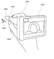
- FIG. 1 is a diagram showing a usage state of an imaging system 1 according to an embodiment of the present disclosure.
- FIG. 2 is a diagram showing a usage state of the imaging system 1 according to an embodiment of the present disclosure.
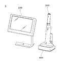
- FIG. 3 is a schematic diagram of an imaging system 1 according to one embodiment of the present disclosure.
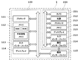
- FIG. 4 is a block diagram showing the configuration of the imaging system 1 according to one embodiment of the present disclosure.
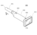
- FIG. 5 is a perspective view showing the configuration of an imaging device 200 according to an embodiment of the present disclosure.
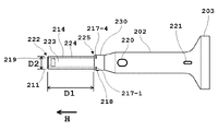
- FIG. 6A is a top view showing the configuration of the imaging device 200 according to one embodiment of the present disclosure.
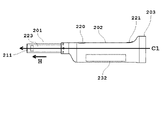
- FIG. 6B is a side view showing the configuration of the imaging device 200 according to one embodiment of the present disclosure.
- FIG. 6C is a front view showing the configuration of the imaging device 200 according to one embodiment of the present disclosure.
- FIG. 6D is a bottom view showing the configuration of the imaging device 200 according to one embodiment of the present disclosure.
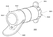
- FIG. 7A is a perspective view showing the configuration of the assisting tool 300 according to one embodiment of the present disclosure.
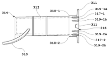
- FIG. 7B is a side view showing the configuration of the assisting tool 300 according to one embodiment of the present disclosure.
- FIG. 8 is a schematic diagram showing usage states of the imaging device 200 and the assisting tool 300 according to an embodiment of the present disclosure.
- FIG. 9 is a schematic diagram showing a cross-sectional configuration of an imaging device 200 according to an embodiment of the present disclosure.
- FIG. 10 is a perspective view showing the configuration of the display 203 of the imaging device 200 according to one embodiment of the present disclosure.
- FIG. 11 is a diagram showing a placement state of the imaging device 200 according to an embodiment of the present disclosure.
- FIG. 12A is a top view showing the configuration of the mounting table 400 according to one embodiment of the present disclosure.
- FIG. 12B is a perspective view showing the configuration of the mounting table 400 according to one embodiment of the present disclosure.
- the imaging system 1 according to the present disclosure is mainly used to image the inside of the oral cavity of a subject to obtain a subject image.
- the imaging system 1 is used to image the back of the larynx of the oral cavity, specifically the pharynx. Therefore, the case where the imaging system 1 according to the present disclosure is used for imaging the pharynx will be mainly described below.
- the pharynx is an example of an imaging region, and naturally, the imaging system 1 according to the present disclosure can be preferably used for other regions as long as they are inside the oral cavity.
- the imaging system 1 is used to output a subject image obtained by imaging the pharynx of the oral cavity. Therefore, in the following, a case of outputting a subject image of the pharynx using the imaging system 1 will be described.
- the imaging system 1 can also be used, for example, to image the pharynx of the oral cavity and determine the possibility of the subject being infected with influenza. Determining the possibility of influenza is one example, and naturally, any disease can be preferably used as long as it is a determination of a disease that causes a difference in findings in the oral cavity due to being afflicted. Examples of such diseases include streptococcal infection, adenovirus infection, EB virus infection, mycoplasma infection, hypertension, and the like.
- the imaging system 1 of the present disclosure is used by the imaging subject himself/herself, is used by a user other than a doctor, is determined or diagnosed by the processing device 100 included in the imaging system 1, or is determined or diagnosed by a doctor. Naturally, it can also include assisting judgment and diagnosis.
- FIG. 1 is a diagram showing a usage state of an imaging system 1 according to an embodiment of the present disclosure.
- FIG. 1 is a diagram showing a usage state of an imaging device 200 in the imaging system 1 according to the present disclosure.
- the user inserts the imaging device 200 into the interior of the assisting device 300 so that the imaging device 200 is covered with the assisting device 300, and the imaging device 200 inserted into the assisting device 300 is inserted into the oral cavity 712 of the subject. Insert device 200 . Therefore, the imaging device 200 is used to image the inside of the oral cavity 712 .
- the imaging device 200 is inserted into the assisting tool 300 from the tip by the user (either the subject 700 himself or a person different from the subject 700).
- the imaging device 200 is inserted into the oral cavity 712 while being covered with the auxiliary tool 300 .
- the tip of the assisting device 300 is inserted through the incisor 711 to the vicinity of the soft palate 713 .
- the imaging device 200 is inserted into the assisting tool 300 from the tip. That is, the imaging device 200 is inserted through the incisor 711 to the vicinity of the soft palate 713 .
- the tongue 714 is pushed downward by the auxiliary tool 300 (which functions as a tongue depressor), and the movement of the tongue 714 is restricted.
- the pharynx 715 located in front of the imaging device 200 is imaged while securing a good field of view of the imaging device 200 .
- the imaged subject image (image of the pharynx 715) is transmitted from the imaging device 200 to the processing device 100 communicably connected by wire or wirelessly.
- the processor of the processing device 100 that has received the subject image processes a program stored in the memory of the processing device 100 to determine the possibility of influenza based on the subject image. Then, the result is output to a display or the like.
- FIG. 2 is a diagram showing a usage state of the imaging system 1 according to one embodiment of the present disclosure.
- FIG. 2 is a diagram showing a state in which the imaging device 200 of the imaging system 1 is held by the user 600 .
- the imaging device 200 is composed of a main body 201, a grip 202 and a display 203 from the side inserted into the oral cavity.
- the main body 201 and the grip 202 are formed in a substantially columnar shape with a predetermined length along the insertion direction H into the oral cavity.
- the display 203 is arranged on the side of the grip 202 opposite to the main body 201 side.
- the imaging device 200 is generally formed in a columnar shape as a whole, and is held by the user 600 by holding it like holding a pencil, as shown in FIG. That is, since the display panel of the display 203 faces the direction of the user 600 himself in the use state, it is possible to easily handle the imaging device 200 while confirming the subject image captured by the imaging device 200 in real time.
- the imaging button 220 is arranged on the upper surface side of the grip. Therefore, when held by the user 600, the user 600 can easily press the imaging button 220 with the index finger or the like.
- the subject image may be a moving image or a still image.
- a through image is captured by the camera, and the captured through image is displayed on the display 203 .
- the camera captures one or more still images, and the captured images are displayed on the display 203 .
- the moving image capturing is started, and the image captured by the camera is displayed on the display 203 during that time.
- imaging button is pressed again, imaging of the moving image ends.
- various images such as through images, still images, and moving images are captured by the camera and displayed on the display. , may contain all of the images captured by the camera.
- FIG. 3 is a schematic diagram of the imaging system 1 according to an embodiment of the present disclosure.
- the imaging system 1 includes a processing device 100 and an imaging device 200 communicably connected to the processing device 100 by wire or wirelessly.
- the processing device 100 receives an operation input by the user and controls imaging by the imaging device 200 .
- the processing device 100 also processes the subject image captured by the imaging device 200 and outputs the processed image to the user, the subject, or the like.
- At least the tip of the imaging device 200 is inserted into the oral cavity of the subject and images the oral cavity, particularly the pharynx.
- the specific imaging process will be described later.
- the captured subject image is transmitted to the processing device 100 via a wired cable or wireless communication.
- the imaging system 1 can further include a mounting table 400 as necessary.
- the mounting table 400 can stably mount the imaging device 200 . Further, by connecting the mounting table 400 to a power supply via a wired cable, it is possible to supply power to the imaging apparatus 200 from the power supply terminal of the mounting table 400 through the power supply port of the imaging apparatus 200 .
- FIG. 4 is a block diagram showing the configuration of the imaging system 1 according to one embodiment of the present disclosure.
- the imaging system 1 includes a processing device 100 including a processor 111, a memory 112, an input interface 113, a display 114 and a communication interface 115, a camera 211, a light source 212, a processor 213, a memory 214, a display panel 215, an input and imaging device 200 including interface 210 and communication interface 216 .
- a processing device 100 including a processor 111, a memory 112, an input interface 113, a display 114 and a communication interface 115, a camera 211, a light source 212, a processor 213, a memory 214, a display panel 215, an input and imaging device 200 including interface 210 and communication interface 216 .
- Each of these components are electrically connected to each other via control lines and data lines.
- the imaging system 1 does not need to include all of the components shown in FIG. 3, and may be configured by omitting some or adding other components
- the processor 111 functions as a control unit that controls other components of the imaging system 1 based on programs stored in the memory 112 .
- the processor 111 controls the driving of the camera 211 and the driving of the light source 212 based on the program stored in the memory 112, stores the subject image received from the imaging device 200 in the memory 112, and reproduces the stored subject image. process.
- the processor 111 accepts an instruction input from the user to the input interface 113, turns on the light source 212, instructs the camera 211 to take an image, and performs a process of turning on the light source 212 and instructing the camera 211 to take an image.
- a process of extracting an image, a process of determining the likelihood of a predetermined disease by subjecting the extracted image to a predetermined process, and a process of outputting the imaged image and the determination result to the display 114 or the like are stored in the memory 112. Executes based on the specified program.
- the processor 111 is mainly composed of one or more CPUs, but may be combined with a GPU or the like as appropriate.
- the memory 112 is composed of RAM, ROM, nonvolatile memory, HDD, etc., and functions as a storage unit.
- the memory 112 stores instruction commands for various controls of the imaging system 1 according to this embodiment as programs. Specifically, the memory 112 accepts an instruction input from the user to the input interface 113, turns on the light source 212, instructs the camera 211 to take an image, and performs a still image that is used to determine disease-likeness from the imaged image. Processes for the processor 111 to execute, such as processing for extracting an image, processing for determining the likelihood of a predetermined disease by subjecting the extracted image to predetermined processing, and processing for outputting the imaged image and the determination result to the display 114 or the like. Memorize the program. In addition to the program, the memory 112 stores a subject image captured by the camera 211 of the imaging device 200, the determination result of disease-likeness by the processor 111, various information of subjects including the subject 700, and the like.
- the processor 111 determines the likelihood of a disease such as influenza from the captured image.
- a large number of images including pharyngeal images of influenza patients labeled as influenza or not, are generated as teacher data, and a determination algorithm is generated by machine learning. do.
- the determination algorithm is applied to the image captured by the imaging device 200, the possibility of influenza is quantified (for example, "98.5%") and indicated.
- the possibility may be indicated by appropriately combining, for example, determination of "positive” and “negative", graded evaluation such as high-medium-low, etc., instead of a specific numerical value.
- the input interface 113 functions as an input unit that receives a user's instruction input to the processing device 100 and the imaging device 200 .
- Examples of the input interface 113 include a "recording button” for instructing the start/end of recording by the imaging device 200, a “confirmation button” for making various selections, and a button for returning to the previous screen or canceling an input confirmation operation.
- a "return/cancel button” for the operation a cross key button for moving icons displayed on the display 114, an on/off key for turning on/off the power of the processing device 100, and the like.
- These various buttons and keys may be physical buttons such as those described above, or may be displayed as icons on the display 114, and may be input using the input interface 113 such as a mouse or keyboard.
- the input interface 113 may be a touch panel that is superimposed on the display 114 and has an input coordinate system corresponding to the display coordinate system of the display 114 . Any method such as a capacitive method, a resistive film method, or the like may be used to detect a user's instruction input through the touch panel. It should be noted that the operation input to the imaging device 200 does not necessarily have to be performed via the input interface 113 of the processing device 100 . It is also possible to use an input interface provided in the imaging device 200 .
- the display 114 functions as a display unit for displaying the subject image captured by the imaging device 200 .
- it is composed of a liquid crystal panel, it is not limited to a liquid crystal panel, and may be composed of an organic EL display, a plasma display, or the like.
- the communication interface 115 functions as a communication unit for transmitting and receiving information with the imaging device 200 and/or other devices. Examples of the information to be sent and received include various commands for instructing the imaging apparatus 200 to start imaging, end imaging, transfer of the subject image, information about the subject, subject images received from the imaging apparatus 200, and the like. mentioned. Examples of such a communication interface 115 include various wired communication terminals such as serial communication terminals such as USB and parallel communication terminals such as IEEE1284.
- a broadband wireless communication system such as the LTE system, a wireless LAN such as the IEEE802.11 system, or a Bluetooth (registered trademark) such as the It is also possible to provide a wireless communication interface that employs a scheme for narrowband wireless communication.
- the camera 211 is driven by an instruction from the processing device 100 and functions as an imaging unit that detects reflected light reflected by the oral cavity, which is a subject, and generates a subject image.
- the camera 211 includes, for example, a CMOS image sensor to detect the light, and a lens system and a drive system for realizing desired functions.
- the image sensor is not limited to a CMOS image sensor, and other sensors such as a CCD image sensor can also be used.
- the camera 211 can have an autofocus function, and is preferably set to focus on a specific part in front of the lens, for example.
- the camera 211 can also have a zoom function, and is preferably set to image at an appropriate magnification according to the size of the pharynx or influenza follicles.
- the lymphoid follicles that appear in the deepest part of the pharynx located in the oral cavity have a pattern unique to influenza. Lymphoid follicles having this unique pattern are called influenza follicles, which are characteristic signs of influenza and are said to appear about 2 hours after onset.
- influenza follicles which are characteristic signs of influenza and are said to appear about 2 hours after onset.
- the imaging system 1 of the present embodiment can be used, for example, to image the pharynx of the oral cavity and detect the follicles to determine the possibility of the subject being infected with influenza. be.
- the camera 211 is inserted into the oral cavity of the subject and is used to image the pharynx deep inside the oral cavity, so the distance between the camera 211 and the subject is relatively short. Therefore, the camera 211 has an angle of view (2 ⁇ ) such that the value calculated by [(distance from the tip of the camera 211 to the posterior wall of the pharynx)*tan ⁇ ] is 20 mm or more vertically and 40 mm or more horizontally.
- the camera 211 it is possible to use a normal camera, but it is also possible to use a so-called wide-angle camera or a super-wide-angle camera.
- the main subject imaged by the camera 211 is the pharynx or influenza follicles formed in the pharynx.
- the pharynx is recessed in the depth direction, so if the depth of field is shallow, the focus shifts between the anterior pharynx and the posterior pharynx. becomes difficult.
- camera 211 has a depth of field of at least 20 mm or more, preferably 30 mm or more. By using a camera having such a depth of field, it is possible to obtain a subject image in which any part from the anterior pharynx to the posterior pharynx is in focus.
- the light source 212 is driven by an instruction from the processing device 100 or the imaging device 200, and functions as a light source unit for irradiating light into the oral cavity.
- Light source 212 includes one or more light sources.
- the light source 212 is composed of one or a plurality of LEDs, and each LED emits light having a predetermined frequency band toward the oral cavity.
- the light source 212 uses light in a desired band from among an ultraviolet light band, a visible light band, and an infrared light band, or a combination thereof. It should be noted that when the processing apparatus 100 determines whether the disease is likely to be influenza or the like, it is preferable to use light in a short wavelength band in the ultraviolet light band. By irradiating influenza follicles with light in this band, specific components of influenza follicles react, so there is a possibility that the likelihood of disease can be determined more reliably.
- the processor 213 functions as a control unit that controls other components of the imaging device 200 based on programs stored in the memory 214 .
- the processor 213 controls the driving of the camera 211 and the light source 212 based on the program stored in the memory 214 , and controls the storage of the subject image captured by the camera 211 in the memory 214 .
- the processor 213 also controls the output to the display 203 and the transmission to the processing device 100 of the subject image and subject information stored in the memory 214 .
- the processor 213 is mainly composed of one or more CPUs, but may be appropriately combined with other processors.
- the memory 214 is composed of RAM, ROM, nonvolatile memory, HDD, etc., and functions as a storage unit.
- the memory 214 stores instruction commands for various controls of the imaging device 200 as programs.
- the memory 214 stores a subject image captured by the camera 211, various types of information about the subject including the subject 700, and the like.
- the display panel 215 is provided on the display 203 and functions as a display unit for displaying a subject image captured by the imaging device 200 .
- it is composed of a liquid crystal panel, it is not limited to a liquid crystal panel, and may be composed of an organic EL display, a plasma display, or the like.
- the input interface 210 functions as an input unit that receives user's instruction input to the processing device 100 and the imaging device 200 .
- Examples of the input interface 210 include a “recording button” for instructing the start and end of recording by the imaging device 200, a “power button” for turning on and off the power of the imaging device 200, and a “power button” for making various selections.
- These various buttons and keys may be physically prepared, or may be displayed as icons on the display 215, and may be displayed using a touch panel or the like superimposed on the display 215 and arranged as the input interface 210. It may be made selectable. Any method such as a capacitive method, a resistive film method, or the like may be used to detect a user's instruction input through the touch panel.
- the communication interface 216 functions as a communication unit for transmitting and receiving information with the imaging device 200 and/or other devices. Examples of the information to be sent and received include various commands for instructing the start of imaging, the end of imaging, the transfer of the subject image received from the imaging device 200, subject information, and the subject image transmitted to the imaging device 200. mentioned.
- a communication interface 115 is provided corresponding to the communication interface of the processing device 100, and examples thereof include various wired communication terminals such as serial communication terminals such as USB and parallel communication terminals such as IEEE1284.
- a broadband wireless communication system such as the LTE system, a wireless LAN such as the IEEE802.11 system, or a Bluetooth (registered trademark) such as the It is also possible to provide a wireless communication interface that employs a scheme for narrowband wireless communication.
- FIG. 5 is a perspective view showing the configuration of an imaging device 200 according to an embodiment of the present disclosure.
- the imaging device 200 accommodates a camera 211 on its inner surface, and is connected to a main body 201 capable of guiding light emitted from a light source 212 into its interior, and a proximal end of the main body 201. It includes a grip 202 held by the user, a diffusion plate 219 arranged at the tip of the main body 201, and a display 203 connected to the base end of the grip 202 and capable of outputting an object image captured by the camera 211.
- an imaging button 220 that the user 600 presses with a finger to instruct the start and end of imaging of the subject, and an imaging button 220 for instructing the power of the imaging device 200 to turn on and off.
- a power button 221 is provided. That is, the start and end of imaging by the imaging device 200 and the turning on and off of the power may be controlled in response to instructions from the processing device 100, or may be controlled in response to pressing of these buttons of the imaging device 200. Sometimes it is.
- FIG. 6A is a top view showing the configuration of the imaging device 200 according to one embodiment of the present disclosure.
- FIG. 6B is a side view showing the configuration of the imaging device 200 according to an embodiment of the present disclosure.
- FIG. 6C is a front view showing the configuration of the imaging device 200 according to an embodiment of the present disclosure.
- FIG. 6D is a bottom view showing the configuration of the imaging device 200 according to an embodiment of the present disclosure. A specific configuration of the imaging device 200 will be described below with reference to FIGS. 6A to 6D.
- the main body 201 has a proximal end 225 and a distal end 222, and has a predetermined length in a direction substantially parallel to the direction in which light is emitted from the light source 212, i.e., the direction H of insertion into the oral cavity. It is composed of pillars. At least the tip 222 of the main body 201 is then inserted into the oral cavity.
- the main body 201 is formed in the shape of a hollow cylindrical column whose cross section is a perfect circle.
- the wall portion 224 may be made of any material as long as it can guide light into the interior thereof, and for example, it can be obtained using a thermoplastic resin.
- Thermoplastic resins include linear polyolefin resins (polypropylene resins, etc.), polyolefin resins such as cyclic polyolefin resins (norbornene resins, etc.), cellulose ester resins such as triacetyl cellulose and diacetyl cellulose, and polyesters. resins, polycarbonate resins, (meth)acrylic resins, polystyrene resins, or mixtures or copolymers thereof. That is, the wall portion 224 of the main body 201 functions as a light guide for guiding the light emitted from the light source into the oral cavity or toward the diffusion plate.
- the main body 201 Since the main body 201 is formed hollow, a housing space 223 is formed on the inner surface by the wall portion 224 .
- the camera 211 is accommodated in this accommodation space 223 .
- the main body 201 only needs to be formed in a columnar shape having the accommodation space 223 . Therefore, the accommodation space 223 does not need to have a cylindrical shape with a perfectly circular cross section, and may have an elliptical or polygonal cross section. Further, the main body 201 does not necessarily have to be hollow inside.
- the length of the main body 201 is determined based on the positional relationship with the subject's incisors.
- a subject forms an oral cavity extending from the incisors toward the back of the throat, and has a pharynx as a subject at the deepest part thereof. Therefore, in order to image the pharynx, the imaging device 200 needs to be inserted up to the vicinity of the soft palate.
- the subject has a distance d1 from the incisors to the soft palate. This distance d1 is described in "Measurement of the inner diameter of the upper airway in sleep apnea syndrome (Nobuo Otani)" J. Am. Jpn. Bronchoesophagol. Soc. (Nikki Shokukaiho), Vol. 40, No. 5, pp, 396-402, it is generally about 70 100 mm to 200 100 mm.
- the body 201 has a distance D1 as the length from the distal end 222 to the proximal end 225 .
- This distance D1 should be 0% to 90% or less, preferably 5% to 80% or less of the distance d1 from the incisors to the soft palate.
- a foreign object is inserted into the back of the throat, one feels vomiting. With the above distance D1, it is possible to prevent vomiting and to maintain an appropriate sense of distance from the subject.
- the width (distance D2) of the main body 201 in the direction perpendicular to the direction connecting the distal end 222 and the proximal end 225 of the main body 201 is, for example, the relationship with the vertical opening width of the mouth of the subject. defined in The subject has a distance d2 as the vertical opening width of the mouth.
- the distance d2 is described in "Statistical Study on Maximum Mouth Mouth in Japanese Healthy Adult Temporomandibular Joints (Hiroyasu Tsukahara et al.)", Journal of the Japan Society of Oral and Maxillofacial Surgery, Vol. 44, No. 2, pp 159-167, it is 3.5 cm to 4.0 cm on average for a typical adult male.
- the imaging device 200 of the present embodiment is inserted into the width of this distance d2 together with the auxiliary tool 300, and the user may take an image while observing the inside of the oral cavity from the gap in which each is inserted. Therefore, it is beneficial not to hinder the visibility of the user when the imaging device 200 is inserted. Therefore, the distance D2 of the main body 201 should be 80% or less, preferably 60% or less of the distance d2, which is the vertical opening width of the mouth, or 3.2 cm or less, preferably 2.4 cm or less. .
- the grip 202 has a connecting portion 230 formed at a position closest to the proximal end 225 of the main body 201 and is connected to the main body 201 via the connecting portion 230 .
- the outer periphery of the connecting portion 230 has engaging projections 217 (217-1 to 217-4) for positioning the auxiliary tool 300 and positioning projections 218. As shown in FIG.
- the engaging projections 217 are engaged with the engaging projections 318 (318-1 to 318-4) provided on the auxiliary tool 300 with each other.
- the positioning protrusion 218 is inserted into an insertion hole 321 provided in the auxiliary tool 300 to position the imaging device 200 and the auxiliary tool 300 relative to each other.
- the engaging projections 217 of the main body 201 include a total of four engaging projections (engaging projections 217-1 to 217-4) that are located on the surface of the grip 202 and on the base of the main body 201. They are evenly spaced at positions near the edge 225 .
- One positioning projection 218 is arranged between the engaging projections 217 on the surface of the grip 202 and near the base end 225 of the main body 201 .
- the arrangement is not limited to this, and only one of the engaging projection 217 and the positioning projection 218 may be arranged.
- the number of the engaging protrusions 217 and the positioning protrusions 218 may be any number as long as the number is one or more.
- the grip 202 includes an imaging button 220 at a position near the proximal end 225 of the main body 201 on its upper surface, that is, near the distal end of the grip 202 in the insertion direction H into the oral cavity.
- the power button 221 is arranged on the upper surface of the grip 202 at a position close to the display 203 , that is, at a position on the opposite side of the grip 202 from the imaging button 220 . As a result, it is possible to prevent the power button 221 from being pressed by mistake while the user 600 is holding and capturing an image.
- the display 203 has a substantially rectangular parallelepiped shape as a whole and is arranged on the same straight line in the direction H as the main body 201 .
- the display 203 includes a display panel on the surface opposite to the direction H in which it is inserted into the oral cavity (that is, the direction toward the user). Therefore, the display 203 is formed such that the surface including the display panel is substantially perpendicular to the longitudinal direction of the main body 201 and the grip 202 which are formed substantially parallel to the direction H of insertion into the oral cavity. be. Then, it is connected to the grip 202 on the side opposite to the oral cavity of the grip 202 on the surface opposite to the surface including the display panel.
- the shape of the display is not limited to a substantially rectangular parallelepiped shape, and may be any shape such as a columnar shape.
- the imaging device 200 can be placed vertically so that the surface including the display panel is in contact with the placement surface. Therefore, the surface including the display panel of the display 203 is formed on a substantially flat surface suitable for placing at least the periphery thereof.
- the diffuser plate 219 is arranged at the tip 222 of the main body 201 and diffuses the light emitted from the light source 212 and passed through the main body 201 toward the intraoral cavity.
- the diffuser plate 219 has a shape corresponding to the cross-sectional shape of the portion of the main body 201 configured to be able to guide light.
- the main body 201 is formed in a hollow cylindrical shape. Therefore, the cross section of diffusion plate 219 is also formed hollow corresponding to the shape.
- the camera 211 is used to generate a subject image by detecting reflected light that has been diffused from the diffusion plate 219, irradiated into the oral cavity, and reflected on the subject.
- the camera 211 is arranged on the same straight line in the direction H as the main body 201 on the inner surface of the wall portion 224 of the main body 201 , that is, in the housing space 223 formed inside the main body 201 .
- the imaging device 200 may include a plurality of cameras. By generating a subject image using a plurality of cameras, the subject image includes information about the three-dimensional shape.
- the camera 211 is arranged in the accommodation space 223 of the main body 201, but the camera 211 can may be placed in
- the main body 201, the grip 202, the display 203 and the camera 211 are arranged on the same straight line along the direction H of insertion into the oral cavity.
- the imaging button 220 and the power button 221 are on the top surface when the imaging apparatus 200 is placed horizontally with the subject image displayed on the display 203 in the normal direction. are placed respectively.
- the grip 202 accommodates a battery that serves as a power source for driving each element of the imaging device 200 .
- the grip 202 has an accommodation space 232 for accommodating the battery therein, and the battery can be accommodated in the accommodation space 232 .
- the imaging device 200 has a central axis C1 along the longitudinal direction (that is, the direction H in which it is inserted into the oral cavity) of the main body 201 formed in a substantially cylindrical shape.
- the battery housing space 232 is located at least partially or wholly below the central axis C1 when the imaging apparatus 200 is placed horizontally with the subject image displayed on the display 203 in a normal orientation.
- the grip 202 and the display 203 are arranged on a line along the central axis C1 of the main body 201 (on a line in the depth direction in FIG. 6C) when viewed from the front end 222 side of the main body 201.
- a camera 211 is arranged inside the main body 201 and on the line along the central axis C1, and is capable of detecting reflected light from a subject incident from the tip of the main body 201.
- the body 201 is formed in a hollow columnar shape having a longitudinal direction in the direction of insertion into the oral cavity (the depth direction in FIG. 6C) by the wall portion 224 , and the diffuser plate 219 is located at the tip of the wall portion 224 . is provided.
- the light source 212 is provided at the rear end of the wall portion 224 (that is, on the base end 225 side of the main body 201), and the light emitted from the light source 212 passes through the wall portion 224 and is emitted from the diffusion plate 219 into the oral cavity. is formed to
- the grip 202 is connected to the proximal end 225 (not shown) side of the main body 201 via a connecting portion 230 .
- the connecting portion 230 is formed in a cylindrical shape similar to the main body 201 so as to follow the outer periphery of the main body 201 having a cylindrical cross section.
- Four engaging protrusions 217-1 to 217-4 are arranged at equal intervals on the outer circumference of the connecting portion 230 formed in a cylindrical shape, and one positioning protrusion 218 is arranged. Although four engaging protrusions and one positioning protrusion are shown in FIG. 6C, other numbers may be used.
- a housing space 232 is provided in the grip 202 so that at least a part or the whole of the center axis C1 of the main body 201 is downward when viewed from the front end 222 side of the main body 201, and the battery is housed in the housing space 232. be done.
- the input/output terminal 229 and the power supply port 228 are arranged on the lower surface when the imaging apparatus 200 is placed horizontally with the subject image displayed on the display 203 in the normal direction. .
- the input/output terminal 229 and the power supply port 228 are arranged on the same surface of the outer periphery of the display 203 .
- FIG. 7A is a perspective view showing a configuration of the auxiliary tool 300 according to an embodiment of the present disclosure.
- the auxiliary tool 300 is an auxiliary tool used for imaging the inside of the oral cavity of the subject. Therefore, when imaging the inside of an oral cavity with the imaging device 200, it is not necessarily required, and may not be used according to a user's or a subject's desire. At least a portion of the imaging device 200 on the distal end side is inserted into the auxiliary tool 300 . Therefore, the auxiliary tool 300 preferably has translucency from the viewpoint of ensuring a good field of view without interfering with the imaging device 200 .
- the auxiliary tool 300 is manufactured by integral molding of resin. However, it may be manufactured from other materials such as paper, cloth, metal, or combinations thereof. Moreover, although the auxiliary tool 300 is preferably of a disposable type, it may be of a reusable type.
- the auxiliary tool 300 includes a tubular main body 312, a pair of gripping plates 311 arranged at the proximal end 316 of the main body 312, and a tongue depressor arranged near the distal end 314 of the main body 312. 315.
- the main body 312 Since the main body 312 is configured to cover at least a part of the main body 201 of the imaging device 200 on the distal end 222 side, the main body 312 has a predetermined length corresponding to the length of the main body 201 . formed into a shape.
- a proximal opening 320 for inserting the imaging device 200 is provided on the proximal end 316 side, and a proximal opening 320 is provided on the distal end 314 side for passing the irradiation light from the light source 212 of the imaging device 200 and the reflected light from the subject. It has a distal opening 313 .
- the assisting device 300 is inserted into the oral cavity from the distal end 314 .
- the main body 201 of the imaging device 200 has substantially constant inner and outer diameters from the proximal end 225 to the distal end 222 . Therefore, the main body 312 of the assisting device 300 also has a substantially constant inner diameter and outer diameter along the longitudinal direction corresponding to this shape.
- the cross-sectional shape of the main body 312 is preferably formed corresponding to the cross-sectional shape of the main body 201 of the imaging device 200, but any shape may be used as long as it can be inserted, such as a perfect circle, an ellipse, and a polygon. Any shape may be used.
- a pair of gripping plates 311 are arranged along the proximal end 316 of the main body 312 .
- the gripping plate 311 is used for gripping by hand when the user inserts the auxiliary tool 300 into the oral cavity of the subject.
- the gripping plate 311 restricts further insertion of the assisting tool 300 by contacting the lip of the subject with the tip side surface of the gripping plate 311 when the assisting tool 300 is inserted into the oral cavity.
- the grip plate 311 has a pair of grip plates arranged symmetrically in the vertical direction on the side of the base end 316 of the main body 312 . It may be formed and its shape may be any shape.
- the tongue depressor 315 is arranged in the lower part of the main body 312 (on the tongue side in the oral cavity) and formed on the blade in the tongue direction.
- the subject's tongue moves in front of the imaging device 200, which hinders imaging of the oral cavity.
- the tongue depressor 315 pushes the tongue downward to limit the movement of the tongue in the oral cavity and prevent the tongue from being positioned in front of the imaging device 200 . Therefore, although the tongue depressor 315 is formed in a blade shape in this embodiment, it may have any shape as long as this function can be realized.
- FIG. 7B is a side showing an outline of the side configuration of the assisting tool 300 according to an embodiment of the present disclosure.
- the assisting device 300 includes the tongue depressor 315 near the distal end 314 side of the main body 312 and the gripping plate 311 on the proximal end 316 side.
- a mechanism for positioning when the imaging device 200 is inserted from the proximal end 316 side is provided on the proximal end 316 side of the main body 312 .
- the main body 312 has a pair of grooves 319 formed with a predetermined length in a direction perpendicular to the outer circumference of the main body 312 , a piece 317 formed by these grooves 319 , and a piece 317 arranged on each of the pieces 317 for imaging. It has an engaging projection 318 configured to engage with each engaging projection 217 arranged at the tip of the grip 202 of the device 200 and an insertion hole 321 into which the positioning projection 218 of the grip 202 is inserted.
- the engaging projections 318 are provided at positions corresponding to the respective engaging projections 217 arranged on the grip 202 of the imaging device 200 and protruding toward the inner surface of the main body 312 . Therefore, in this embodiment, four engaging projections 318-1 to 318-4 are arranged at positions corresponding to the four engaging projections 217-1 to 217-4. Also, the insertion hole 321 is provided at a position corresponding to the positioning protrusion 218 arranged on the grip 202 of the imaging device 200 . Therefore, in this embodiment, one insertion hole 321 is arranged at a position corresponding to one positioning protrusion 218 .
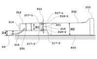
- FIG. 8 is a schematic diagram showing a usage state of the imaging device 200 and the auxiliary tool 300 according to an embodiment of the present disclosure.
- Each mechanism located at the proximal end 316 of the body 312 of FIG. 7B will now be described with reference to FIG. First, when the imaging device 200 is inserted into the proximal end 316 of the auxiliary tool 300 and reaches the vicinity of the distal end 314, the engagement projection 217 formed to protrude outward from the grip 202 of the imaging device 200 and the main body of the auxiliary tool 300 An engaging protrusion 318 formed toward the inner surface of 312 abuts thereon.
- the engaging protrusions 318-1 to 318-4 of the main body 312 are formed by a piece 317-1 formed by a pair of grooves 319-1a and 319-1b to 319-4a and 319-4b. ⁇ 317-4. Therefore, when a force is further applied in the direction of inserting the imaging device 200 in a state where the engaging projection 217 of the imaging device 200 and the engaging projection 318 of the auxiliary tool 300 are in contact with each other, the piece 317 formed by the pair of grooves 319 is displaced. be lifted. As a result, the engaging protrusion 217 of the imaging device 200 is further inserted beyond the engaging protrusion 318 of the auxiliary tool 300 .
- the positioning projection 218 provided on the grip 202 of the imaging device 200 protrudes outward and is inserted into the insertion hole 321 of the auxiliary tool 300 . is inserted into Then, the positioning projection 218 of the imaging device 200 comes into contact with the wall surface of the insertion hole 321 formed on the distal end 314 side. As a result, further insertion of the imaging device 200 in the direction of the distal end 314 of the assisting device 300 is restricted.
- the imaging device 200 when the imaging device 200 is completely inserted into the auxiliary tool 300, movement of the imaging device 200 in the insertion direction is restricted by the positioning protrusion 218 and the insertion hole 321.
- FIG. 8 shows a case where the imaging device 200 is placed horizontally on the placement surface 800 while the subject image is displayed on the display 203 in a normal orientation.
- the main body 201 has a vertical width H1
- the grip 202 has a vertical width H2 larger than the width H1. Since the main body 201 and the grip 202 are configured such that their upper surfaces are flush with each other, the position of the main body 201 from the mounting surface 800 is increased by the difference between the width H1 and the width H2. That is, when the lower surface of the display 203 and the lower surface of the grip 202 are placed in contact with the mounting surface 800 , the tip portion of the main body 201 is configured not to contact the mounting surface 800 . This makes it possible to prevent the tip portion of the main body 201 from being contaminated.
- the tongue depressor 315 of the auxiliary tool 300 is formed to protrude downward from the lower surface of the main body 312 by a distance D3.
- the lower surface of the main body 312 of the tongue depressor is mounted on the main body 201 of the imaging device 200 so as to be separated from the mounting surface 800 by a distance D4.
- the tongue depressor 315 by forming the tongue depressor 315 so that the distance D3 is shorter than the distance D4, it is possible to prevent the tongue depressor 315 from coming into contact with the mounting surface 800 and being contaminated.
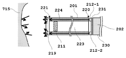
- FIG. 9 is a schematic diagram illustrating a cross-sectional configuration of an imaging device 200 according to an embodiment of the present disclosure.
- a total of four light sources 212 - 1 to 212 - 4 are arranged on a substrate 231 arranged on the tip side of the grip 202 .
- the light sources 212 each include an LED, and light having a predetermined frequency band is emitted from each LED toward the oral cavity.
- the light emitted from the light source 212 enters the base end 225 of the main body 201 and is guided toward the diffusion plate 219 by the wall portion 224 of the main body 201 .
- the light reaching the diffuser plate 219 is diffused by the diffuser plate 219 into the oral cavity. Then, the light diffused by the diffusion plate 219 is reflected by the object such as the pharynx 715 . When this reflected light reaches the camera 211, a subject image is generated.
- the light sources 212-1 to 212-4 may be configured to be controlled independently. For example, by illuminating some of the light sources 212-1 to 212-4, the shadow of a subject having a three-dimensional shape (such as influenza follicles) can be included in the subject image. As a result, the subject image includes information about the three-dimensional shape of the subject, making it possible to more clearly identify the subject and more accurately determine the possibility of influenza infection by the determination algorithm.
- a subject having a three-dimensional shape such as influenza follicles
- the light sources 212-1 to 212-4 are arranged on the base end 225 side of the main body 201, but the tip 222 of the main body 201 or the main body 201 may be located on the perimeter of the
- the diffusion plate 219 is used to prevent the light emitted from the light source 212 from illuminating only a part of the oral cavity and to generate uniform light. Therefore, as an example, a lens-shaped diffusion plate is used in which a fine lens array is formed on the surface of the diffusion plate 219 and has an arbitrary diffusion angle. Alternatively, a diffuser plate that can diffuse light by other methods, such as a diffuser plate that achieves a light diffusion function with fine irregularities randomly arranged on the surface, may be used. Furthermore, the diffuser plate 219 may be configured integrally with the main body 201 . For example, it can be realized by a method such as forming fine unevenness on the tip portion of the main body 201 .
- the diffusion plate 219 is arranged on the tip 222 side of the main body 201 .
- the present invention is not limited to this, as long as it is between the light source 212 and the oral cavity to be irradiated with it. ) may be placed.
- FIG. 10 is a perspective view showing the configuration of the display 203 of the imaging device 200 according to an embodiment of the present disclosure.
- the display 203 is arranged on the proximal side of the grip 202 (opposite to the direction H in which it is inserted into the oral cavity).
- the display 203 has a substantially rectangular parallelepiped shape as a whole, and has a rectangular display panel 215 on the surface facing the user (the side opposite to the side to which the grip 202 is connected).
- the display panel 215 displays the subject image captured by the camera 211.
- the body 201, the grip 202, and the display 203 are arranged on the same straight line, so the display panel 215 does not display the subject image. It is possible to easily capture an image with the imaging device 200 while confirming the subject image.
- a frame 226 is arranged around the display panel 215 of the display 203, and a pedestal 227 is formed along the periphery of the frame 226.
- the pedestal 227 is formed to protrude from the surface of the display panel 215 by a height D5 in the direction of the user, that is, in the direction opposite to the direction H of insertion into the oral cavity.
- Such pedestals 227 are provided at positions facing at least three sides (all four sides in the example of FIG. 10) of the sides of the rectangular display panel 215 (the pedestals 227-1 to 227-1 to 227-2). -4).
- the pedestal 227 is configured as a continuous pedestal along the outer periphery of the display panel 215 .
- the pedestal 227 may be provided at a position facing at least three of the sides of the display panel 215 . Therefore, the pedestal 227 does not necessarily have to be formed continuously, and may be provided only on a part of each side.
- FIG. 11 is a diagram showing the mounting state of the imaging device 200 according to one embodiment of the present disclosure. Specifically, FIG. 11 shows a diagram in which the imaging device 200 is placed on the placement surface 800 so that the main body 201 faces upward and the display 203 is positioned downward. As described with reference to FIG. 10, the frame 226 is formed along the periphery of the display panel 215, and the pedestal 227 is further formed along the periphery thereof. The pedestal 227 is formed higher than the surface of the display panel 215 by a height D5. Therefore, when placed on the placement surface 800 , the surface of the pedestal 227 contacts the placement surface 800 to prevent the display panel 215 from directly contacting the placement surface 800 . In other words, the pedestal 227 can prevent the display panel 215 from being damaged.
- the pedestal 227 is formed to have a substantially uniform height as a whole with respect to the four sides forming the user-side surface of the rectangular parallelepiped display 203. . Therefore, when the imaging device 200 is placed on the mounting surface 800 with the surface facing downward, the imaging device 200 can be stably mounted on the mounting surface 800 without using a separate member such as a mounting table. is.
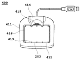
- FIG. 12A is a top view showing the configuration of the mounting table 400 according to an embodiment of the present disclosure.
- FIG. 12B is a perspective view showing the configuration of the mounting table 400 according to an embodiment of the present disclosure.
- the mounting table 400 stably mounts the imaging apparatus 200, and is connected to a power supply via a wired cable as necessary, so that the imaging apparatus 200 is connected to the imaging apparatus 200 from the power supply terminal of the mounting table 400 through the power supply port of the imaging apparatus 200. Used to supply power.
- the mounting table 400 has a support base 411 that supports the imaging device 200 from below and constitutes the main body of the mounting table.
- the support base 411 is formed in a substantially rectangular parallelepiped shape as a whole, it is not limited to this shape and may have another shape.
- the support base 411 has an accommodation hole 412 on its upper surface for mounting the imaging device 200 so that the main body 201 of the imaging device 200 is positioned upward and the display 203 is positioned downward.
- the accommodation hole 412 is formed so that the shape of the side wall follows the outline of the display 203 of the imaging device 200 (broken line in FIG. 12A) and has a predetermined depth.
- the imaging device 200 when the imaging device 200 is placed on the mounting table 400 , the imaging device 200 is positioned by the side wall of the accommodation hole 412 .
- the accommodation hole 412 has, on its bottom surface, one or more projections 413 having a predetermined height (but lower than the height of the side walls) and a projection 413 having a predetermined height (but lower than the height of the side walls). has one or more linear projections 416 having The protrusion 413 and the linear protrusion 416 are provided at positions corresponding to the base 227 provided on the user side of the display 203, and support the base 227 from below.
- a space is formed between the display panel 215 of the display 203 and the bottom surface of the receiving hole 412 by the height of the pedestal 227 and the height of the protrusions 413 and linear protrusions 416 . This prevents the display panel 215 from being damaged by the bottom surface of the receiving hole 412 .
- the mounting table 400 supports the vicinity of the grip 202 of the imaging device 200 from the side when the imaging device 200 is mounted in the accommodation hole 412 so that the main body 201 of the imaging device 200 is positioned upward and the display 203 is positioned downward. It has a support stand 414 for The support stand 414 is arranged above the support base 411 and formed to have a predetermined length in the height direction. Also, the surface facing the grip 202 is formed along the outer shape of the grip 202 . It should be noted that the support stand 414 itself need not always contact and support the vicinity of the grip 202 of the imaging device 200, and may only come into contact when the imaging device 200 is tilted, for example.
- the mounting table 400 has a power feeding portion 417 formed at a position facing the lower surface of the display 203 of the imaging device 200 (that is, the surface on which the power feeding port 228 is arranged) when the imaging device 200 is placed in the accommodation hole 412 . It is A power supply terminal 415 is formed on a surface of the power supply unit 417 facing the lower surface of the display 203 and at a position facing the power supply port 228 of the imaging device 200 . Therefore, when the imaging device 200 is placed in the accommodation hole 412 , the power supply port 228 is connected to the power supply terminal 415 of the mounting table 400 , and power is supplied from the power supply terminal 415 to the power supply port 228 .
- the input/output terminal 229 is arranged on the lower surface of the display 203 of the imaging device 200, that is, on the same surface as the power supply port 228 is arranged.
- the power supply port 228 is connected to the power supply terminal 415 arranged at the opposite position, but the input/output terminal 229 faces the lower surface of the display 203 of the power supply unit 417 . It will be covered by the side face. Therefore, when power is being supplied through the power supply port 228, wired connection of the input/output terminal 229 becomes impossible, and competition with power through the input/output terminal 229 can be prevented.
- each member of the main body 201, the grip 202, the display 203, and the camera 211 is arranged on the same straight line as the main body 201 in the direction of insertion into the oral cavity. Therefore, it is possible to provide the operator with excellent operability.
- the processing device 100 and the imaging device 200 are communicably connected via a wireless or wired cable and the processing device 100 processes a subject image
- the imaging device 200 itself may be provided with various processing functions for subject images.
- the imaging device 200 itself may be equipped with the determination function of the processing device 100 to determine disease-likeness.
- the processed image may be output to the processing device 100 or another device connected by wire or wirelessly.
- the imaging device 200 and the assisting tool 300 are configured separately has been described.
- both may be integrally configured.
- the imaging device 200 may have a tongue depressor for restricting movement of the tongue in the oral cavity on the lingual surface of the main body 201 so as to be positioned on the lingual side of the oral cavity. By doing so, it is possible to take an image without using the auxiliary tool 300 .
- Imaging system 100 Processing device 111 : Processor 112 : Memory 113 : Input interface 114 : Display 115 : Communication interface 200 : Imaging device 201 : Main body 202 : Grip 203 : Display 211 : Camera 212 : Light source 212-1 : Light source 213 : Processor 214 : Memory 215 : Display panel 216 : Communication interface 217 : Engagement projection 217-1 : Engagement projection 218 : Positioning projection 219 : Diffusion plate 220 : Imaging button 221 : Power button 222 : Tip 223 : Accommodation space 224 : Wall portion 225 : Base end 226 : Frame 227 : Pedestal 227-1 : Pedestal 228 : Feeding port 229 : Input/output terminal 230 : Connecting portion 231 : Substrate 232 : Housing space 300 : Auxiliary tool 311 : Grasping plate 312 : Main body 313 : Distal side opening 3
Landscapes
- Health & Medical Sciences (AREA)
- Life Sciences & Earth Sciences (AREA)
- Engineering & Computer Science (AREA)
- Surgery (AREA)
- Physics & Mathematics (AREA)
- Veterinary Medicine (AREA)
- Public Health (AREA)
- Animal Behavior & Ethology (AREA)
- General Health & Medical Sciences (AREA)
- Biophysics (AREA)
- Biomedical Technology (AREA)
- Pathology (AREA)
- Optics & Photonics (AREA)
- Heart & Thoracic Surgery (AREA)
- Medical Informatics (AREA)
- Molecular Biology (AREA)
- Radiology & Medical Imaging (AREA)
- Nuclear Medicine, Radiotherapy & Molecular Imaging (AREA)
- Dentistry (AREA)
- Oral & Maxillofacial Surgery (AREA)
- Theoretical Computer Science (AREA)
- General Physics & Mathematics (AREA)
- Epidemiology (AREA)
- General Engineering & Computer Science (AREA)
- Software Systems (AREA)
- Mathematical Physics (AREA)
- Human Computer Interaction (AREA)
- Databases & Information Systems (AREA)
- Data Mining & Analysis (AREA)
- Audiology, Speech & Language Pathology (AREA)
- Endoscopes (AREA)
Abstract
Description
<第1実施形態>
1.撮像システム1の概要
本開示に係る撮像システム1は、主に被験者の口腔の内部を撮像し被写体画像を得るために用いられる。特に、当該撮像システム1は、口腔の喉奥周辺、具体的には咽頭を撮像するために用いられる。したがって、以下においては、本開示に係る撮像システム1を咽頭の撮像に用いた場合について主に説明する。ただし、咽頭は撮像部位の一例であって、当然に、口腔内であれば他の部位であっても、本開示に係る撮像システム1を好適に用いることができる。
図3は、本開示の一実施形態に係る撮像システム1の概略図である。図3によれば、撮像システム1は、処理装置100と、当該処理装置100に有線又は無線で通信可能に接続された撮像装置200とを含む。処理装置100は、使用者による操作入力を受け付けて、撮像装置200による撮像を制御する。また、処理装置100は、撮像装置200によって撮像された被写体画像を処理して使用者、対象者等へ処理後の画像を出力する。
本開示に係る撮像システム1は、処理装置100で処理するための画像を撮像する撮像装置200を含む。図5は、本開示の一実施形態に係る撮像装置200の構成を示す斜視図である。図5によると、撮像装置200は、その内面にカメラ211が収容されるとともに、その内部に光源212から照射された光を導光することが可能な本体201、本体201の基端に接続され使用者によって把持されるグリップ202と、本体201の先端に配置される拡散板219と、グリップ202の基端に接続されカメラ211によって撮像された被写体画像を出力可能なディスプレイ203とを含む。
図7Aは、本開示の一実施形態に係る補助具300の構成を示す斜視図である。補助具300は、対象者の口腔内の撮像のために使用される補助的な道具である。したがって、撮像装置200で口腔内を撮像する場合に、必ず必要とするものではなく、使用者又は対象者の所望に応じて使用されなくてもよい。補助具300には、撮像装置200の少なくとも先端側の一部が挿入される。したがって、補助具300は、撮像装置200の邪魔にならず良好な視野を確保するという観点から、透光性を有することが好ましい。
図8は、本開示の一実施形態に係る撮像装置200と補助具300の使用状態を示す概略図である。以下、図7Bの本体312の基端316に配置される各機構について、図8を参照しつつ説明する。まず、撮像装置200が補助具300の基端316に挿入され、先端314近傍まで達すると、撮像装置200のグリップ202の外方向に突出して形成された係合突起217と、補助具300の本体312の内面に向かって形成された係合突起318とが当接する。ここで、本実施形態においては、本体312の係合突起318-1~318-4は、一対の溝319-1a及び319-1b~319-4a及び319-4bによって形成された片317-1~317-4に形成されている。したがって、撮像装置200の係合突起217と補助具300の係合突起318が当接した状態でさらに撮像装置200を挿入する方向に力が加わると、一対の溝319で形成された片317が持ち上げられる。これによって、撮像装置200の係合突起217が、補助具300の係合突起318を越えてさらに挿入される。
図9は、本開示の一実施形態に係る撮像装置200の断面の構成を示す概略図である。図9によると、光源212は、グリップ202の先端側に配置された基板231上に、合計4個の光源212-1~212-4が配置される。光源212は、一例としては、それぞれLEDで構成され、各LEDから所定の周波数帯域を有する光が口腔の方向に向かって照射される。具体的には、光源212から照射された光は、本体201の基端225に入光し、本体201の壁部224によって、拡散板219方向に導光される。拡散板219に達した光は、拡散板219によって口腔内に拡散される。そして、拡散板219によって拡散された光は、被写体である咽頭715等に反射する。この反射光がカメラ211に到達することで、被写体画像が生成される。
図10は、本開示の一実施形態に係る撮像装置200のディスプレイ203の構成を示す斜視図である。ディスプレイ203は、グリップ202の基端側(口腔に挿入される方向Hとは反対側)に配置される。ディスプレイ203は、全体として略直方体形状をし、使用者側(グリップ202が連結される側とは反対側)の面に矩形状に形成された表示パネル215を有する。表示パネル215には、カメラ211で撮像した被写体画像が表示されるが、これまで説明したとおり、本体201、グリップ202及びディスプレイ203が同一直線状に配置されているために、ディスプレイ203に表示された被写体画像を確認しつつ容易に撮像装置200で撮像することが可能となる。
図12Aは、本開示の一実施形態に係る載置台400の構成を示す上面図である。また、図12Bは、本開示の一実施形態に係る載置台400の構成を示す斜視図である。載置台400は、撮像装置200を安定的に載置するとともに、必要に応じて有線ケーブルを介して電源に接続して、載置台400の給電端子から撮像装置200の給電ポートを通じて撮像装置200に電力を供給するために用いられる。
上記実施形態においては、処理装置100と撮像装置200とが、無線又は有線ケーブルを介して通信可能に接続されている場合について説明した。しかし、これに限らず、撮像装置200で撮像された被写体画像は、無線通信によって遠隔に設置されたサーバー装置(例えば、クラウドサーバー装置)に送信し、サーバー装置を処理装置として機能させることも可能である。具体的には、サーバー装置で疾患らしさを判定したり、遠隔に設置された医者用端末装置に送信し、当該装置を処理装置として機能させることで、医者の所見とともに判定したりすることも可能である。
100 :処理装置
111 :プロセッサ
112 :メモリ
113 :入力インターフェイス
114 :ディスプレイ
115 :通信インターフェイス
200 :撮像装置
201 :本体
202 :グリップ
203 :ディスプレイ
211 :カメラ
212 :光源
212-1 :光源
213 :プロセッサ
214 :メモリ
215 :表示パネル
216 :通信インターフェイス
217 :係合突起
217-1 :係合突起
218 :位置決め突起
219 :拡散板
220 :撮像ボタン
221 :電源ボタン
222 :先端
223 :収容空間
224 :壁部
225 :基端
226 :額縁
227 :台座
227-1 :台座
228 :給電ポート
229 :入出力端子
230 :連結部
231 :基板
232 :収容空間
300 :補助具
311 :把持板
312 :本体
313 :先端側開口
314 :先端
315 :舌圧子
316 :基端
317 :片
317-1 :片
318 :係合突起
318-1 :係合突起
319 :溝
319-1a :溝
320 :基端側開口
321 :挿入穴
400 :載置台
411 :支持台
412 :収容穴
413 :突起
414 :支持スタンド
415 :給電端子
416 :線状突起
417 :給電部
600 :使用者
700 :対象者
711 :門歯
712 :口腔
713 :軟口蓋
714 :舌
715 :咽頭
800 :載置面
Claims (15)
- 基端と先端を備え、前記基端と前記先端との間が所定長の略柱状に形成され、少なくとも前記先端を口腔に挿入可能に、長手方向が前記口腔に挿入される方向に沿うように構成された本体と、
所定の周波数帯域の光を前記口腔に向かって照射するために、前記本体よりも基端側又は前記本体の内部に配置されように構成された一又は複数の光源と、
使用者が把持するために、前記本体の前記基端側に、前記本体の長手方向に沿って所定長の略柱状に形成され、前記本体と同一直線上に配置されるように構成されたグリップと、
前記光源から照射され前記口腔に反射した反射光に基づいて被写体画像を撮像するために、前記本体よりも基端側又は前記本体の内部に、前記本体と同一直線上に配置されるように構成されたカメラと、
前記カメラで撮像された被写体画像を表示するために、前記グリップの前記口腔とは反対側であって、前記本体と同一直線状に配置されるように構成されたディスプレイと、
を含む撮像装置。 - 前記被写体画像は咽頭を撮像した画像である、請求項1に記載の撮像装置。
- 前記所定の周波数帯域は紫外光帯域である、請求項1又は2に記載の撮像装置。
- 前記ディスプレイは、前記被写体画像を表示するための表示パネルと、
前記表示パネルの周囲の少なくとも一部が、前記表示パネルの表面から前記口腔とは反対の方向に向かって突出するように構成された台座と、
を含む請求項1~3のいずれか一項に記載の撮像装置。 - 前記表示パネルは矩形状に形成され、
前記台座は、矩形状に形成された前記表示パネルの各辺に相対するように構成される、
請求項4に記載の撮像装置。 - 前記台座は、前記本体が上方になり前記ディスプレイが下方になるように前記撮像装置を載置面上に載置したときに、前記表示パネルが前記載置面に直接接触するのを防止するように構成された、請求項4又は5に記載の撮像装置。
- 前記台座が載置面上に接することで、前記撮像装置を載置するための載置台を用いることなく、前記本体が上方になり前記ディスプレイが下方になるように前記撮像装置を載置面上に載置することが可能である、請求項4~6のいずれか一項に記載の撮像装置。
- 前記グリップは、その内部にバッテリを収容するための収容空間を含む、請求項1~7のいずれか一項に記載の撮像装置。
- 前記ディスプレイに前記被写体画像が通常の向きに表示された状態で前記撮像装置を水平方向に置いたとき、前記収容空間は前記長手方向に沿った前記本体の中心軸よりも下方に位置する、請求項8に記載の撮像装置。
- 前記グリップは、前記ディスプレイに前記被写体画像が通常の向きに表示される向きのとき、前記グリップの上面側に位置するように構成された撮像ボタンを含む、請求項1~9のいずれか一項に記載の撮像装置。
- 前記撮像装置は、前記本体の前記基端と前記先端とを結ぶ方向において、少なくとも一部が筒状の補助具に挿入されることによって被覆される、請求項1~10のいずれか一項に記載の撮像装置。
- 前記撮像装置は、前記撮像装置に対して電力を外部から供給するための給電ポートを含む、請求項1~11のいずれか一項に記載の撮像装置。
- 前記ディスプレイの外形に沿うようにその収容面の形状が形成された載置台に対して、前記本体が上方になり前記ディスプレイが下方になるように前記撮像装置が載置されたとき前記給電ポートが前記載置台の給電端子に連結され、前記電力の供給がなされる、請求項12に記載の撮像装置。
- 前記撮像装置は、外部に有線によって情報の送受信をするために入出力端子を含み、
前記給電ポートと前記入出力端子は、前記ディスプレイの外周の同一面上に配置される、
請求項12又は13に記載の撮像装置。 - 請求項1~14のいずれか一項に記載の撮像装置と、
前記撮像装置に有線又は無線によって通信可能に接続され、前記撮像装置によって撮像された被写体画像を処理するように構成された処理装置と、
を含む撮像システム。
Priority Applications (7)
| Application Number | Priority Date | Filing Date | Title |
|---|---|---|---|
| EP21939245.3A EP4331534A4 (en) | 2021-04-28 | 2021-04-28 | IMAGE CAPTURE DEVICE AND IMAGE CAPTURE SYSTEM |
| CN202180097620.XA CN117202871A (zh) | 2021-04-28 | 2021-04-28 | 拍摄装置以及拍摄系统 |
| KR1020237037032A KR20240004380A (ko) | 2021-04-28 | 2021-04-28 | 촬상 장치 및 촬상 시스템 |
| PCT/JP2021/016891 WO2022230084A1 (ja) | 2021-04-28 | 2021-04-28 | 撮像装置及び撮像システム |
| JP2023516929A JP7801787B6 (ja) | 2021-04-28 | 2021-04-28 | 撮像装置及び撮像システム |
| US18/491,991 US12582307B2 (en) | 2021-04-28 | 2023-10-23 | Image capturing device and image capturing system |
| JP2025277742A JP2026053542A (ja) | 2021-04-28 | 2025-12-23 | 撮像装置及び撮像システム |
Applications Claiming Priority (1)
| Application Number | Priority Date | Filing Date | Title |
|---|---|---|---|
| PCT/JP2021/016891 WO2022230084A1 (ja) | 2021-04-28 | 2021-04-28 | 撮像装置及び撮像システム |
Related Child Applications (1)
| Application Number | Title | Priority Date | Filing Date |
|---|---|---|---|
| US18/491,991 Continuation US12582307B2 (en) | 2021-04-28 | 2023-10-23 | Image capturing device and image capturing system |
Publications (1)
| Publication Number | Publication Date |
|---|---|
| WO2022230084A1 true WO2022230084A1 (ja) | 2022-11-03 |
Family
ID=83847892
Family Applications (1)
| Application Number | Title | Priority Date | Filing Date |
|---|---|---|---|
| PCT/JP2021/016891 Ceased WO2022230084A1 (ja) | 2021-04-28 | 2021-04-28 | 撮像装置及び撮像システム |
Country Status (6)
| Country | Link |
|---|---|
| US (1) | US12582307B2 (ja) |
| EP (1) | EP4331534A4 (ja) |
| JP (2) | JP7801787B6 (ja) |
| KR (1) | KR20240004380A (ja) |
| CN (1) | CN117202871A (ja) |
| WO (1) | WO2022230084A1 (ja) |
Families Citing this family (3)
| Publication number | Priority date | Publication date | Assignee | Title |
|---|---|---|---|---|
| JP7267608B2 (ja) * | 2017-12-28 | 2023-05-02 | アイリス株式会社 | 口内撮影装置、医療装置及びプログラム |
| USD1082892S1 (en) * | 2022-03-08 | 2025-07-08 | Aillis Inc. | Camera |
| JP1757889S (ja) * | 2022-12-20 | 2023-11-21 | 充電台 |
Citations (8)
| Publication number | Priority date | Publication date | Assignee | Title |
|---|---|---|---|---|
| JP2002218286A (ja) * | 2001-01-19 | 2002-08-02 | Fuji Photo Film Co Ltd | デジタルカメラ |
| JP2002238849A (ja) * | 2000-12-15 | 2002-08-27 | Sirona Dental Systems Gmbh | 医療的な診断、特に歯科的な診断のための手持ち器具 |
| JP2004081845A (ja) * | 2002-08-22 | 2004-03-18 | Kaltenbach & Voigt Gmbh & Co | 医療及び歯科医療用ハンドピース |
| JP2007316528A (ja) * | 2006-05-29 | 2007-12-06 | Fujifilm Corp | カメラ |
| JP2010197510A (ja) * | 2009-02-23 | 2010-09-09 | Aof Imaging Technology Ltd | 防水型電子機器 |
| US20120281135A1 (en) * | 2009-09-14 | 2012-11-08 | Herbert Gebhardt | Handpiece Camera |
| JP2018175722A (ja) | 2017-04-20 | 2018-11-15 | 株式会社モリタ東京製作所 | 口腔内写真撮影システム |
| WO2019131327A1 (ja) * | 2017-12-28 | 2019-07-04 | アイリス株式会社 | 口内撮影装置、医療装置及びプログラム |
Family Cites Families (10)
| Publication number | Priority date | Publication date | Assignee | Title |
|---|---|---|---|---|
| DE102004001856B4 (de) * | 2003-01-14 | 2019-05-23 | J. Morita Mfg. Corp. | Bilderstellungsgerät für Diagnosezwecke |
| JP4813898B2 (ja) * | 2005-12-26 | 2011-11-09 | 株式会社カナガワファニチュア | 口腔内撮影用デジタルカメラ |
| JP5145587B2 (ja) * | 2007-12-27 | 2013-02-20 | 晃一 角田 | 口腔挿入具および口腔咽頭鏡装置 |
| EP2866644B1 (en) * | 2012-06-27 | 2023-11-08 | 3Shape A/S | 3d intraoral scanner measuring fluorescence |
| US9808148B2 (en) * | 2013-03-14 | 2017-11-07 | Jan Erich Sommers | Spatial 3D sterioscopic intraoral camera system |
| US10108269B2 (en) * | 2015-03-06 | 2018-10-23 | Align Technology, Inc. | Intraoral scanner with touch sensitive input |
| WO2019023631A1 (en) * | 2017-07-27 | 2019-01-31 | Align Technology, Inc. | SYSTEM AND METHODS FOR TREATING AN ORTHODONTIC ALIGNMENT USING OPTICAL COHERENCE TOMOGRAPHY |
| US12144661B2 (en) * | 2019-12-31 | 2024-11-19 | Align Technology, Inc. | Gesture control using an intraoral scanner |
| US12011337B2 (en) * | 2021-01-26 | 2024-06-18 | Align Technology, Inc. | Wireless intraoral scanner for distributed intraoral scanning system |
| US12611096B2 (en) * | 2022-07-22 | 2026-04-28 | Align Technology, Inc. | Minimalistic intraoral scanning system |
-
2021
- 2021-04-28 CN CN202180097620.XA patent/CN117202871A/zh active Pending
- 2021-04-28 EP EP21939245.3A patent/EP4331534A4/en active Pending
- 2021-04-28 KR KR1020237037032A patent/KR20240004380A/ko not_active Ceased
- 2021-04-28 JP JP2023516929A patent/JP7801787B6/ja active Active
- 2021-04-28 WO PCT/JP2021/016891 patent/WO2022230084A1/ja not_active Ceased
-
2023
- 2023-10-23 US US18/491,991 patent/US12582307B2/en active Active
-
2025
- 2025-12-23 JP JP2025277742A patent/JP2026053542A/ja active Pending
Patent Citations (8)
| Publication number | Priority date | Publication date | Assignee | Title |
|---|---|---|---|---|
| JP2002238849A (ja) * | 2000-12-15 | 2002-08-27 | Sirona Dental Systems Gmbh | 医療的な診断、特に歯科的な診断のための手持ち器具 |
| JP2002218286A (ja) * | 2001-01-19 | 2002-08-02 | Fuji Photo Film Co Ltd | デジタルカメラ |
| JP2004081845A (ja) * | 2002-08-22 | 2004-03-18 | Kaltenbach & Voigt Gmbh & Co | 医療及び歯科医療用ハンドピース |
| JP2007316528A (ja) * | 2006-05-29 | 2007-12-06 | Fujifilm Corp | カメラ |
| JP2010197510A (ja) * | 2009-02-23 | 2010-09-09 | Aof Imaging Technology Ltd | 防水型電子機器 |
| US20120281135A1 (en) * | 2009-09-14 | 2012-11-08 | Herbert Gebhardt | Handpiece Camera |
| JP2018175722A (ja) | 2017-04-20 | 2018-11-15 | 株式会社モリタ東京製作所 | 口腔内写真撮影システム |
| WO2019131327A1 (ja) * | 2017-12-28 | 2019-07-04 | アイリス株式会社 | 口内撮影装置、医療装置及びプログラム |
Non-Patent Citations (3)
| Title |
|---|
| HIROYASU TSUKAHARA: "A statistical evaluation of normal maximal mouth opening of Japanese adults", JAPANESE SOCIETY OF ORAL AND MAXILLOFACIAL SURGEONS, vol. 44, no. 2, pages 159 - 167 |
| NOBUO OHYA, M. D.: "Pharyngeal Cross-sectional Area in Sleep Apnea Syndrome", J. JPN. BRONCHOESOPHAGOL. SOC., vol. 40, no. 5, pages 396 - 402 |
| See also references of EP4331534A4 |
Also Published As
| Publication number | Publication date |
|---|---|
| JPWO2022230084A1 (ja) | 2022-11-03 |
| JP2026053542A (ja) | 2026-03-25 |
| JP7801787B6 (ja) | 2026-02-19 |
| CN117202871A (zh) | 2023-12-08 |
| US20240041311A1 (en) | 2024-02-08 |
| JP7801787B2 (ja) | 2026-01-19 |
| KR20240004380A (ko) | 2024-01-11 |
| EP4331534A1 (en) | 2024-03-06 |
| EP4331534A4 (en) | 2025-03-05 |
| US12582307B2 (en) | 2026-03-24 |
Similar Documents
| Publication | Publication Date | Title |
|---|---|---|
| JP2026053542A (ja) | 撮像装置及び撮像システム | |
| TWI461174B (zh) | 口腔插入器及咽喉鏡裝置 | |
| JP4813898B2 (ja) | 口腔内撮影用デジタルカメラ | |
| CN100553553C (zh) | 多功能成像装置和用于该装置的适配器 | |
| US9931021B2 (en) | Method for identifying objects in a subject's ear | |
| JP7715393B2 (ja) | 撮像装置及び撮像システム | |
| CN101032391A (zh) | 内窥镜装置以及显示装置 | |
| JP2010035971A (ja) | 内視鏡機器及びそれに用いられる内視鏡ユニット | |
| WO2020145238A1 (ja) | 口腔内観察デバイス | |
| KR20190027888A (ko) | 진찰 시야 확보식 비디오 스코프 | |
| US20230289926A1 (en) | Processing device, processing program, processing method, and processing system | |
| JP7819968B2 (ja) | 補助具、撮影装置、プログラム及び方法 | |
| JP5669667B2 (ja) | 内視鏡システム | |
| KR20190027510A (ko) | 치과용 서포트 블록 및 이를 포함하는 영상 촬영 장치 | |
| JP3224557U (ja) | 医療用スコープ | |
| JPH03106328A (ja) | 内視鏡検査用ベッド装置 | |
| ITPD950047A1 (it) | Telecamera endoscopica, in particolare per la ripresa di immagini della cavita' orale |
Legal Events
| Date | Code | Title | Description |
|---|---|---|---|
| 121 | Ep: the epo has been informed by wipo that ep was designated in this application |
Ref document number: 21939245 Country of ref document: EP Kind code of ref document: A1 |
|
| WWE | Wipo information: entry into national phase |
Ref document number: 2023516929 Country of ref document: JP |
|
| WWE | Wipo information: entry into national phase |
Ref document number: 202180097620.X Country of ref document: CN |
|
| WWE | Wipo information: entry into national phase |
Ref document number: 2021939245 Country of ref document: EP |
|
| NENP | Non-entry into the national phase |
Ref country code: DE |
|
| ENP | Entry into the national phase |
Ref document number: 2021939245 Country of ref document: EP Effective date: 20231128 |