WO2022230163A1 - 電気デバイス用正極材料並びにこれを用いた電気デバイス用正極および電気デバイス - Google Patents
電気デバイス用正極材料並びにこれを用いた電気デバイス用正極および電気デバイス Download PDFInfo
- Publication number
- WO2022230163A1 WO2022230163A1 PCT/JP2021/017154 JP2021017154W WO2022230163A1 WO 2022230163 A1 WO2022230163 A1 WO 2022230163A1 JP 2021017154 W JP2021017154 W JP 2021017154W WO 2022230163 A1 WO2022230163 A1 WO 2022230163A1
- Authority
- WO
- WIPO (PCT)
- Prior art keywords
- positive electrode
- solid electrolyte
- sulfur
- active material
- electrode material
- Prior art date
- Legal status (The legal status is an assumption and is not a legal conclusion. Google has not performed a legal analysis and makes no representation as to the accuracy of the status listed.)
- Ceased
Links
Images



Classifications
-
- H—ELECTRICITY
- H01—ELECTRIC ELEMENTS
- H01M—PROCESSES OR MEANS, e.g. BATTERIES, FOR THE DIRECT CONVERSION OF CHEMICAL ENERGY INTO ELECTRICAL ENERGY
- H01M4/00—Electrodes
- H01M4/02—Electrodes composed of, or comprising, active material
- H01M4/36—Selection of substances as active materials, active masses, active liquids
- H01M4/58—Selection of substances as active materials, active masses, active liquids of inorganic compounds other than oxides or hydroxides, e.g. sulfides, selenides, tellurides, halogenides or LiCoFy; of polyanionic structures, e.g. phosphates, silicates or borates
- H01M4/581—Chalcogenides or intercalation compounds thereof
- H01M4/5815—Sulfides
-
- H—ELECTRICITY
- H01—ELECTRIC ELEMENTS
- H01M—PROCESSES OR MEANS, e.g. BATTERIES, FOR THE DIRECT CONVERSION OF CHEMICAL ENERGY INTO ELECTRICAL ENERGY
- H01M4/00—Electrodes
- H01M4/02—Electrodes composed of, or comprising, active material
- H01M4/13—Electrodes for accumulators with non-aqueous electrolyte, e.g. for lithium-accumulators; Processes of manufacture thereof
- H01M4/136—Electrodes based on inorganic compounds other than oxides or hydroxides, e.g. sulfides, selenides, tellurides, halogenides or LiCoFy
-
- H—ELECTRICITY
- H01—ELECTRIC ELEMENTS
- H01M—PROCESSES OR MEANS, e.g. BATTERIES, FOR THE DIRECT CONVERSION OF CHEMICAL ENERGY INTO ELECTRICAL ENERGY
- H01M10/00—Secondary cells; Manufacture thereof
- H01M10/05—Accumulators with non-aqueous electrolyte
- H01M10/052—Li-accumulators
-
- H—ELECTRICITY
- H01—ELECTRIC ELEMENTS
- H01M—PROCESSES OR MEANS, e.g. BATTERIES, FOR THE DIRECT CONVERSION OF CHEMICAL ENERGY INTO ELECTRICAL ENERGY
- H01M10/00—Secondary cells; Manufacture thereof
- H01M10/05—Accumulators with non-aqueous electrolyte
- H01M10/052—Li-accumulators
- H01M10/0525—Rocking-chair batteries, i.e. batteries with lithium insertion or intercalation in both electrodes; Lithium-ion batteries
-
- H—ELECTRICITY
- H01—ELECTRIC ELEMENTS
- H01M—PROCESSES OR MEANS, e.g. BATTERIES, FOR THE DIRECT CONVERSION OF CHEMICAL ENERGY INTO ELECTRICAL ENERGY
- H01M10/00—Secondary cells; Manufacture thereof
- H01M10/05—Accumulators with non-aqueous electrolyte
- H01M10/056—Accumulators with non-aqueous electrolyte characterised by the materials used as electrolytes, e.g. mixed inorganic/organic electrolytes
- H01M10/0561—Accumulators with non-aqueous electrolyte characterised by the materials used as electrolytes, e.g. mixed inorganic/organic electrolytes the electrolyte being constituted of inorganic materials only
- H01M10/0562—Solid materials
-
- H—ELECTRICITY
- H01—ELECTRIC ELEMENTS
- H01M—PROCESSES OR MEANS, e.g. BATTERIES, FOR THE DIRECT CONVERSION OF CHEMICAL ENERGY INTO ELECTRICAL ENERGY
- H01M4/00—Electrodes
- H01M4/02—Electrodes composed of, or comprising, active material
- H01M4/04—Processes of manufacture in general
- H01M4/0471—Processes of manufacture in general involving thermal treatment, e.g. firing, sintering, backing particulate active material, thermal decomposition, pyrolysis
-
- H—ELECTRICITY
- H01—ELECTRIC ELEMENTS
- H01M—PROCESSES OR MEANS, e.g. BATTERIES, FOR THE DIRECT CONVERSION OF CHEMICAL ENERGY INTO ELECTRICAL ENERGY
- H01M4/00—Electrodes
- H01M4/02—Electrodes composed of, or comprising, active material
- H01M4/13—Electrodes for accumulators with non-aqueous electrolyte, e.g. for lithium-accumulators; Processes of manufacture thereof
- H01M4/139—Processes of manufacture
- H01M4/1397—Processes of manufacture of electrodes based on inorganic compounds other than oxides or hydroxides, e.g. sulfides, selenides, tellurides, halogenides or LiCoFy
-
- H—ELECTRICITY
- H01—ELECTRIC ELEMENTS
- H01M—PROCESSES OR MEANS, e.g. BATTERIES, FOR THE DIRECT CONVERSION OF CHEMICAL ENERGY INTO ELECTRICAL ENERGY
- H01M4/00—Electrodes
- H01M4/02—Electrodes composed of, or comprising, active material
- H01M4/36—Selection of substances as active materials, active masses, active liquids
- H01M4/362—Composites
- H01M4/364—Composites as mixtures
-
- H—ELECTRICITY
- H01—ELECTRIC ELEMENTS
- H01M—PROCESSES OR MEANS, e.g. BATTERIES, FOR THE DIRECT CONVERSION OF CHEMICAL ENERGY INTO ELECTRICAL ENERGY
- H01M4/00—Electrodes
- H01M4/02—Electrodes composed of, or comprising, active material
- H01M4/36—Selection of substances as active materials, active masses, active liquids
- H01M4/38—Selection of substances as active materials, active masses, active liquids of elements or alloys
-
- H—ELECTRICITY
- H01—ELECTRIC ELEMENTS
- H01M—PROCESSES OR MEANS, e.g. BATTERIES, FOR THE DIRECT CONVERSION OF CHEMICAL ENERGY INTO ELECTRICAL ENERGY
- H01M4/00—Electrodes
- H01M4/02—Electrodes composed of, or comprising, active material
- H01M4/62—Selection of inactive substances as ingredients for active masses, e.g. binders, fillers
- H01M4/624—Electric conductive fillers
- H01M4/625—Carbon or graphite
-
- H—ELECTRICITY
- H01—ELECTRIC ELEMENTS
- H01M—PROCESSES OR MEANS, e.g. BATTERIES, FOR THE DIRECT CONVERSION OF CHEMICAL ENERGY INTO ELECTRICAL ENERGY
- H01M4/00—Electrodes
- H01M4/02—Electrodes composed of, or comprising, active material
- H01M2004/021—Physical characteristics, e.g. porosity, surface area
-
- H—ELECTRICITY
- H01—ELECTRIC ELEMENTS
- H01M—PROCESSES OR MEANS, e.g. BATTERIES, FOR THE DIRECT CONVERSION OF CHEMICAL ENERGY INTO ELECTRICAL ENERGY
- H01M4/00—Electrodes
- H01M4/02—Electrodes composed of, or comprising, active material
- H01M2004/026—Electrodes composed of, or comprising, active material characterised by the polarity
- H01M2004/028—Positive electrodes
-
- H—ELECTRICITY
- H01—ELECTRIC ELEMENTS
- H01M—PROCESSES OR MEANS, e.g. BATTERIES, FOR THE DIRECT CONVERSION OF CHEMICAL ENERGY INTO ELECTRICAL ENERGY
- H01M2300/00—Electrolytes
- H01M2300/0017—Non-aqueous electrolytes
- H01M2300/0065—Solid electrolytes
- H01M2300/0068—Solid electrolytes inorganic
-
- Y—GENERAL TAGGING OF NEW TECHNOLOGICAL DEVELOPMENTS; GENERAL TAGGING OF CROSS-SECTIONAL TECHNOLOGIES SPANNING OVER SEVERAL SECTIONS OF THE IPC; TECHNICAL SUBJECTS COVERED BY FORMER USPC CROSS-REFERENCE ART COLLECTIONS [XRACs] AND DIGESTS
- Y02—TECHNOLOGIES OR APPLICATIONS FOR MITIGATION OR ADAPTATION AGAINST CLIMATE CHANGE
- Y02E—REDUCTION OF GREENHOUSE GAS [GHG] EMISSIONS, RELATED TO ENERGY GENERATION, TRANSMISSION OR DISTRIBUTION
- Y02E60/00—Enabling technologies; Technologies with a potential or indirect contribution to GHG emissions mitigation
- Y02E60/10—Energy storage using batteries
Definitions
- the present invention relates to a positive electrode material for electrical devices, a positive electrode for electrical devices using the same, and an electrical device.
- Metallic lithium which is a negative electrode active material that supplies lithium ions to the positive electrode, is known as a high-capacity negative electrode material that can be used in all-solid-state batteries.
- the battery characteristics may deteriorate as a result of the reaction between the metallic lithium and the sulfide solid electrolyte. .
- an object of the present invention is to provide means capable of improving capacity characteristics and charge/discharge rate characteristics in an electrical device using a positive electrode active material containing sulfur.
- the present inventors have diligently studied to solve the above problems.
- the above problems can be solved by using a positive electrode material for an electrical device that includes a sulfur-containing positive electrode active material and a sulfur-containing solid electrolyte that exhibits a peak in a predetermined wavenumber region of the Raman spectrum. and completed the present invention.
- FIG. 1 is a perspective view showing the appearance of a flat laminated all-solid lithium secondary battery that is an embodiment of the present invention.
- FIG. 2 is a cross-sectional view along line 2-2 shown in FIG.
- FIG. 3A is a schematic cross-sectional view of a positive electrode material in the prior art.
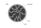
- FIG. 3B is a cross-sectional schematic diagram of a positive electrode material according to one embodiment of the present invention.
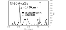
- 4A is a graph showing a Raman spectrum obtained by micro-Raman spectroscopic measurement using a laser with a wavelength of 532 nm for the powder particles of the positive electrode material for electrical devices prepared in Example 1.
- FIG. 1 is a perspective view showing the appearance of a flat laminated all-solid lithium secondary battery that is an embodiment of the present invention.
- FIG. 2 is a cross-sectional view along line 2-2 shown in FIG.
- FIG. 3A is a schematic cross-sectional view of a positive electrode material in the prior art.
- FIG. 3B is
- FIG. 4B is a graph showing a Raman spectrum obtained by micro-Raman spectroscopic measurement using a laser with a wavelength of 532 nm for the powder particles of the positive electrode material for an electric device prepared in Comparative Example 1.
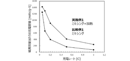
- FIG. 5 is a graph showing changes in charge capacity values when the positive electrode materials obtained in Example 1 and Comparative Example 1 were charged at different charging rates.
- One form of the present invention includes a positive electrode active material containing sulfur and a solid electrolyte containing sulfur, and has a peak in the range of 1400 to 1450 cm in the Raman spectrum of micro - Raman spectrometry using a laser with a wavelength of 532 nm. It is a positive electrode material for electrical devices that shows According to the positive electrode material for an electrical device according to the present embodiment, it is possible to improve capacity characteristics and charge/discharge rate characteristics in an electrical device using a sulfur-containing positive electrode active material.
- FIG. 1 is a perspective view showing the appearance of a flat laminated all-solid lithium secondary battery that is an embodiment of the present invention.
- FIG. 2 is a cross-sectional view along line 2-2 shown in FIG.
- a flat laminated non-bipolar lithium ion secondary battery hereinafter also simply referred to as a "laminated battery" shown in FIGS. 1 and 2 will be described in detail as an example.
- the laminated battery 10a has a rectangular flat shape, and from both sides thereof, a negative electrode collector plate 25 and a positive electrode collector plate 27 for extracting electric power are pulled out.
- the power generation element 21 is wrapped by the battery exterior material (laminate film 29) of the laminated battery 10a, and the periphery thereof is heat-sealed. It is sealed in the pulled out state.
- the laminate type battery 10a of the present embodiment has a structure in which a flat and substantially rectangular power generation element 21 in which charge/discharge reactions actually progress is sealed inside a laminate film 29 that is a battery exterior material.
- the power generation element 21 has a structure in which a positive electrode, a solid electrolyte layer 17, and a negative electrode are laminated.
- the positive electrode has a structure in which positive electrode active material layers 15 containing a positive electrode active material are arranged on both sides of a positive electrode current collector 11′′.
- the negative electrode contains a negative electrode active material on both sides of a negative electrode current collector 11′. It has a structure in which the active material layer 13 is arranged, whereby the adjacent positive electrode, solid electrolyte layer and negative electrode form one cell layer 19 .
- the negative electrode current collector 11′ and the positive electrode current collector 11′′ are attached with a negative electrode current collector plate (tab) 25 and a positive electrode current collector plate (tab) 27, which are electrically connected to the electrodes (positive electrode and negative electrode), respectively. It has a structure in which it is sandwiched between the ends of the laminate film 29, which is the material, and led out of the laminate film 29. Main constituent members of the lithium-ion secondary battery according to this embodiment will be described below. .
- the current collector has a function of mediating transfer of electrons from the electrode active material layer. There are no particular restrictions on the material that constitutes the current collector. In addition, if the negative electrode active material layer and the positive electrode active material layer to be described later themselves have conductivity and can exhibit a current collecting function, a current collector is used as a member separate from these electrode active material layers. No need.
- the negative electrode active material layer 13 contains a negative electrode active material.
- the types of negative electrode active materials are not particularly limited, but include carbon materials, metal oxides and metal active materials.
- a metal containing lithium may also be used as the negative electrode active material.
- Such a negative electrode active material is not particularly limited as long as it is an active material containing lithium, and examples thereof include metallic lithium and lithium-containing alloys.
- Lithium-containing alloys include, for example, alloys of Li and at least one of In, Al, Si and Sn.
- the negative electrode active material preferably contains metallic lithium or a lithium-containing alloy, a silicon-based negative electrode active material, or a tin-based negative electrode active material, and particularly preferably contains metallic lithium or a lithium-containing alloy.
- metal lithium or a lithium-containing alloy is used as the negative electrode active material
- the lithium secondary battery as an electrical device deposits lithium metal as the negative electrode active material on the negative electrode current collector during the charging process, a so-called lithium deposition type. can be of Therefore, in such a form, the thickness of the negative electrode active material layer increases as the charging process progresses, and the thickness of the negative electrode active material layer decreases as the discharging process progresses.
- the negative electrode active material layer does not have to exist at the time of complete discharge, depending on the situation, a certain amount of the negative electrode active material layer made of lithium metal may be arranged at the time of complete discharge.
- the content of the negative electrode active material in the negative electrode active material layer is not particularly limited. more preferred.
- the negative electrode active material layer preferably further contains a solid electrolyte.
- a solid electrolyte By including the solid electrolyte in the negative electrode active material layer, the ion conductivity of the negative electrode active material layer can be improved.
- solid electrolytes include sulfide solid electrolytes and oxide solid electrolytes, and sulfide solid electrolytes are preferred.
- Examples of sulfide solid electrolytes include LiI—Li 2 S—SiS 2 , LiI—Li 2 SP 2 O 5 , LiI—Li 3 PO 4 —P 2 S 5 , Li 2 SP 2 S 5 , LiI - Li3PS4 , LiI - LiBr - Li3PS4 , Li3PS4 , Li2SP2S5 - LiI , Li2SP2S5 - Li2O , Li2SP 2S5 - Li2O - LiI, Li2S - SiS2 , Li2S - SiS2 - LiI, Li2S - SiS2 - LiBr, Li2S - SiS2-LiCl, Li2S - SiS2 -B 2 S 3 -LiI, Li 2 S-SiS 2 -P 2 S 5 -LiI, Li 2 S-B 2 S 3 , Li 2 SP 2 S 5 -Z m S n (where m,
- the sulfide solid electrolyte may have, for example, a Li 3 PS 4 skeleton, a Li 4 P 2 S 7 skeleton, or a Li 4 P 2 S 6 skeleton.
- sulfide solid electrolytes having a Li 3 PS 4 skeleton include LiI--Li 3 PS 4 , LiI--LiBr--Li 3 PS 4 and Li 3 PS 4 .
- sulfide solid electrolytes having a Li 4 P 2 S 7 skeleton include Li—P—S solid electrolytes called LPS (eg, Li 7 P 3 S 11 ).
- the sulfide solid electrolyte for example, LGPS represented by Li (4-x) Ge (1-x) P x S 4 (where x satisfies 0 ⁇ x ⁇ 1) may be used.
- the sulfide solid electrolyte contained in the active material layer is preferably a sulfide solid electrolyte containing the element P, and the sulfide solid electrolyte is a material containing Li 2 SP 2 S 5 as a main component. It is more preferable to have Furthermore, the sulfide solid electrolyte may contain halogens (F, Cl, Br, I).
- the sulfide solid electrolyte comprises Li6PS5X , where X is Cl, Br or I, preferably Cl.
- the ionic conductivity (eg, Li ion conductivity) of the sulfide solid electrolyte at room temperature (25° C.) is, for example, preferably 1 ⁇ 10 ⁇ 5 S/cm or more, and 1 ⁇ 10 ⁇ 4 S/cm or more. is more preferable.
- the value of the ionic conductivity of the solid electrolyte can be measured by the AC impedance method.
- oxide solid electrolytes examples include compounds having a NASICON structure.
- oxide solid electrolytes include LiLaTiO (e.g., Li 0.34 La 0.51 TiO 3 ), LiPON (e.g., Li 2.9 PO 3.3 N 0.46 ), LiLaZrO (e.g., , Li 7 La 3 Zr 2 O 12 ) and the like.
- the content of the solid electrolyte in the negative electrode active material layer is, for example, preferably within the range of 1 to 60% by mass, more preferably within the range of 10 to 50% by mass.
- the negative electrode active material layer may further contain at least one of a conductive aid and a binder in addition to the negative electrode active material and solid electrolyte described above.
- the thickness of the negative electrode active material layer varies depending on the configuration of the intended secondary battery, it is preferably in the range of 0.1 to 1000 ⁇ m, for example.
- the solid electrolyte layer is a layer interposed between the positive electrode active material layer and the negative electrode active material layer and essentially containing a solid electrolyte.
- the specific form of the solid electrolyte contained in the solid electrolyte layer is not particularly limited, and the solid electrolytes exemplified in the column of the negative electrode active material layer and their preferred forms can be similarly employed.
- the solid electrolyte layer may further contain a binder in addition to the predetermined solid electrolyte described above.
- the thickness of the solid electrolyte layer varies depending on the intended configuration of the lithium ion secondary battery, but from the viewpoint of improving the volume energy density of the battery, it is preferably 600 ⁇ m or less, more preferably 500 ⁇ m or less. , and more preferably 400 ⁇ m or less.
- the lower limit of the thickness of the solid electrolyte layer is not particularly limited, but is preferably 1 ⁇ m or more, more preferably 5 ⁇ m or more, and still more preferably 10 ⁇ m or more.
- the positive electrode active material layer contains the positive electrode material for electrical devices according to one embodiment of the present invention.
- the positive electrode material for an electrical device essentially contains a positive electrode active material containing sulfur and a solid electrolyte containing sulfur, and preferably further contains a conductive material.
- the type of the positive electrode active material containing sulfur is not particularly limited, but examples thereof include elemental sulfur (S) and lithium sulfide (Li 2 S), as well as particles or thin films of organic sulfur compounds or inorganic sulfur compounds. Any substance can be used as long as it can release lithium ions during charging and absorb lithium ions during discharging by utilizing a reduction reaction.
- Inorganic sulfur compounds are particularly preferred because of their excellent stability, and specific examples include elemental sulfur (S), TiS 2 , TiS 3 , TiS 4 , NiS, NiS 2 , CuS, FeS 2 , Li 2 S, MoS 2 , MoS 3 , MnS, MnS 2 , CoS, CoS 2 and the like.
- S, S-carbon composites, TiS 2 , TiS 3 , TiS 4 , FeS 2 and MoS 2 are preferred, and elemental sulfur (S) and lithium sulfide (Li 2 S), TiS 2 and FeS 2 are more preferred. From the viewpoint of high capacity, elemental sulfur (S) and lithium sulfide (Li 2 S) are particularly preferred.
- the positive electrode material according to this embodiment may further contain a sulfur-free positive electrode active material in addition to the sulfur-containing positive electrode active material.
- the ratio of the content of the sulfur-containing positive electrode active material to 100% by mass of the total amount of the positive electrode active material is preferably 50% by mass or more, more preferably 70% by mass or more, and still more preferably 80% by mass. more preferably 90% by mass or more, particularly preferably 95% by mass or more, and most preferably 100% by mass.
- the positive electrode material according to this embodiment essentially contains a solid electrolyte containing sulfur.
- the specific form of the sulfur-containing solid electrolyte contained in the positive electrode material according to the present embodiment is not particularly limited, and the sulfur-containing solid electrolytes and their preferred forms exemplified in the column of the negative electrode active material layer can be similarly adopted.
- the solid electrolyte contained in the positive electrode material according to the present embodiment is preferably a sulfide solid electrolyte.
- the sulfur-containing solid electrolyte contained in the solid electrolyte layer contains alkali metal atoms.
- Alkali metal atoms that can be contained in the sulfur-containing solid electrolyte include lithium atoms, sodium atoms, and potassium atoms. Among them, lithium atoms are preferable because of their excellent ion conductivity.
- the solid electrolyte contained in the solid electrolyte layer contains alkali metal atoms (e.g., lithium atoms, sodium atoms or potassium atoms; preferably lithium atoms), phosphorus atoms and/or boron atoms. It is a thing.
- the sulfide solid electrolyte comprises Li6PS5X , where X is Cl, Br or I, preferably Cl. Since these solid electrolytes have high ionic conductivity, they can effectively contribute to manifestation of the effects of the present invention.
- the positive electrode material according to this embodiment preferably further contains a conductive material.
- the specific form of the conductive material contained in the positive electrode material according to this embodiment is not particularly limited, and conventionally known materials can be appropriately employed.
- the positive electrode material according to the present embodiment contains a conductive material, it is more preferable that the conductive material has pores.
- the interior of the pores can be filled with the positive electrode active material and the solid electrolyte, and a three-phase interface composed of these three materials is formed to further promote the positive electrode reaction. It has the advantage of being easier.
- the conductive material having pores is preferably a carbon material from the viewpoint of excellent conductivity, ease of processing, and ease of designing a desired pore distribution.
- carbon materials having pores include activated carbon, Ketjenblack (registered trademark) (highly conductive carbon black), (oil) furnace black, channel black, acetylene black, thermal black, carbon black such as lamp black, Examples thereof include carbon particles (carbon carriers) made of coke, natural graphite, artificial graphite, and the like.
- the main component of the carbon material is carbon.
- "mainly composed of carbon” means containing carbon atoms as the main component, and is a concept that includes both consisting only of carbon atoms and consisting essentially of carbon atoms.
- the phrase “substantially composed of carbon atoms” means that 2 to 3% by mass or less of impurities can be mixed.
- the BET specific surface area of the conductive material (preferably carbon material) having pores is preferably 200 m 2 /g or more, more preferably 500 m 2 /g or more, and 800 m 2 /g or more. is more preferable, 1200 m 2 /g or more is particularly preferable, and 1500 m 2 /g or more is most preferable.
- the pore volume of the conductive material is preferably 1.0 mL/g or more, more preferably 1.3 mL/g or more, and even more preferably 1.5 mL/g or more.
- the BET specific surface area and the pore volume of the conductive material are values within such ranges, it is possible to retain a sufficient amount of pores, and consequently to retain a sufficient amount of the positive electrode active material. Become.
- the BET specific surface area and pore volume of the conductive material can be measured by nitrogen adsorption/desorption measurement. This nitrogen adsorption/desorption measurement is performed using BELSORP mini manufactured by Microtrac Bell Co., Ltd. at a temperature of -196°C by a multipoint method.
- the BET specific surface area is obtained from the adsorption isotherm in the relative pressure range of 0.01 ⁇ P/P 0 ⁇ 0.05.
- the pore volume is determined from the volume of adsorbed N2 at a relative pressure of 0.96.
- the average pore diameter of the conductive material is not particularly limited, it is preferably 50 nm or less, particularly preferably 30 nm or less. If the average pore diameter is a value within these ranges, electrons can be sufficiently supplied to the active material located away from the pore walls in the positive electrode active material containing sulfur arranged inside the pores. can be done.
- the average pore size of the conductive material can be calculated by nitrogen adsorption/desorption measurement in the same manner as described above.
- the average particle size (primary particle size) when the conductive material is particulate is not particularly limited, but is preferably 0.05 to 50 ⁇ m, more preferably 0.1 to 20 ⁇ m. , 0.5 to 10 ⁇ m.
- the "particle diameter of the conductive material” means the maximum distance L among the distances between any two points on the contour line of the conductive material.
- the value of the "average particle size of the conductive material” is the particle size of particles observed in several to several tens of fields of view using an observation means such as a scanning electron microscope (SEM) or a transmission electron microscope (TEM). A value calculated as an average value shall be adopted.
- the positive electrode material according to the present embodiment includes a sulfur-containing positive electrode active material and a sulfur-containing solid electrolyte.
- the positive electrode material further includes a conductive material having pores, at least one Part of the solid electrolyte and at least part of the positive electrode active material are preferably arranged on the inner surfaces of the pores of the conductive material so as to be in contact with each other.
- FIG. 3A is a schematic cross-sectional view of a positive electrode material 100' in the prior art.
- FIG. 3B is a cross-sectional schematic diagram of the positive electrode material 100 which concerns on one Embodiment of this invention.
- a carbon material (for example, activated carbon) 110 which is a conductive material, has a large number of pores 110a.
- the pores 110a are filled with sulfur 120, which is a positive electrode active material.
- This positive electrode active material (sulfur) 120 is also arranged on the surface of the carbon material (activated carbon) 110 .
- cathode material 100 ′ shown in FIG.
- the solid electrolyte 130 is placed only on the surface of the carbon material (activated carbon) 110 .
- the positive electrode material 100 according to one embodiment of the present invention shown in FIG. It is present in a highly dispersed state in the positive electrode active material (sulfur) 120 . More specifically, a continuous phase composed of the positive electrode active material (sulfur) 120 is filled inside the pores 110a and is also present on the surface of the carbon material (activated carbon) 110, and the solid electrolyte 130 is present in the continuous phase.
- element mapping derived from each material is performed using energy dispersive X-ray spectroscopy (EDX), and the obtained element It is possible to confirm the arrangement form of each material by using the map or the count number of elements derived from each material with respect to the count number of all elements as an index.
- the sulfur-containing solid electrolyte essentially contains phosphorus atoms and there is no possibility that the phosphorus atoms are derived from another material, the element map for phosphorus is obtained. , it is possible to confirm the configuration of the solid electrolyte from its distribution.
- the ratio of the count number of phosphorus to the count number of all elements in EDX is also possible to confirm the configuration of the solid electrolyte from the ratio of the count number of phosphorus to the count number of all elements in EDX.
- the ratio of the count number of elements derived only from the solid electrolyte to the count number of all elements in EDX If the value is 0.10 or more, it can be determined that the solid electrolyte is arranged inside the pores of the conductive material.
- the value of the ratio is preferably 0.15 or more, more preferably 0.20 or more, still more preferably 0.26 or more, and particularly preferably 0.35 or more.
- the value of the ratio is within these ranges. can be expressed more prominently.
- the preferable upper limit of the value of the ratio but an example of a preferable upper limit is 0.50 or less, more preferably 0.45 or less.
- the positive electrode material for an electric device is characterized by showing a peak in the range of 1400 to 1450 cm ⁇ 1 in the Raman spectrum obtained by microscopic Raman spectrometry using a laser with a wavelength of 532 nm for the powder particles of the positive electrode material.
- FIG. 4A is a graph showing a Raman spectrum obtained by performing microscopic Raman spectroscopic measurement using a laser with a wavelength of 532 nm for powder particles of a positive electrode material for an electrical device prepared in Example 1 described later. is.
- the Raman spectrum of the positive electrode material for electrical devices according to the present embodiment first shows peaks in the region of 600 cm ⁇ 1 or lower, which are considered to be derived from the sulfur active material and the sulfide solid electrolyte.
- the Raman spectrum of the positive electrode material for electrical devices according to the present embodiment is characterized in that, in addition to the peaks described above, a peak is also observed near 1430 cm ⁇ 1 .
- the peak in the range of 1400 to 1450 cm -1 in the Raman spectrum of microscopic Raman spectroscopy using a laser with a wavelength of 532 nm for the positive electrode active material containing sulfur and the solid electrolyte containing sulfur has been found that when an electric device such as an all-solid lithium secondary battery is constructed using a positive electrode material exhibiting this, it is possible to significantly improve capacity characteristics and charge/discharge rate characteristics. Although the mechanism has not been completely clarified, the following mechanism is presumed.
- the positive electrode material having the predetermined peak according to the present embodiment is obtained by, for example, mixing a sulfur-containing positive electrode active material and a sulfur-containing solid electrolyte to obtain a mixture as described later, and then comparing the mixture with a It can be produced by heating at a high temperature (185° C. in Example 1).
- a high temperature 185° C. in Example 1
- Comparative Example 1 in which this heat treatment was not performed, no peak in the range of 1400 to 1450 cm ⁇ 1 was observed as shown in FIG. 4B. For this reason, at the interface where the positive electrode active material containing sulfur and the solid electrolyte containing sulfur are in contact during the above-described heat treatment at a relatively high temperature, an intermediate layer made of a component having excellent ion conductivity is formed.
- the charge-discharge reaction can proceed sufficiently even when the charge-discharge cycle proceeds, and the capacity is reduced. It is believed that the characteristics and cycle durability are greatly improved.
- the positive electrode material according to the present embodiment contributes to the excellent capacity characteristics and charge/discharge rate characteristics.
- the reason why the positive electrode material according to the present embodiment contributes to the excellent capacity characteristics and charge/discharge rate characteristics is the ion conductive compound present at the contact interface between the sulfur-containing positive electrode active material and the sulfur-containing solid electrolyte. presumed to be due to the presence of It is believed that this ion-conducting compound is produced by heat treatment at a relatively high temperature. Therefore, it is considered that the positive electrode material according to this embodiment is obtained by heat-treating a mixture of a sulfur-containing positive electrode active material and a sulfur-containing solid electrolyte at a high temperature.
- the temperature of the heat treatment is not particularly limited, but is preferably higher than 170°C, more preferably 175°C or higher, still more preferably 180°C or higher, and particularly preferably 185°C or higher.
- the upper limit of the heat treatment temperature is also not particularly limited, but is, for example, 250° C. or less, preferably 200° C. or less.
- the heat treatment time is not particularly limited, but may be about 1 to 5 hours.
- the sulfur-containing positive electrode active material and the sulfur-containing solid electrolyte may be present in the form of a mixture, but the mixture preferably further contains a conductive material.
- the positive electrode active material containing sulfur and the solid electrolyte containing sulfur are filled into the pores of the conductive material by the heat treatment described above, and a large number of three-phase interfaces are formed.
- a formed positive electrode material can be obtained in a preferred form.
- the means for obtaining the mixture containing the above three components is not particularly limited, but examples include mixing treatment using a mixing means such as a mortar, and milling treatment using a pulverizing means such as a planetary ball mill. is mentioned. Above all, from the viewpoint of obtaining a larger initial capacity and better charge/discharge rate characteristics, it is preferable to subject the mixture obtained by the milling treatment to the above heat treatment.
- a mixture of a positive electrode active material containing sulfur and a solid electrolyte containing sulfur is obtained by mixing or milling, and then the mixture is subjected to the heat treatment described above. good too.
- the positive electrode material according to one embodiment of the present invention containing the above three components can also be obtained by additionally adding a conductive material and performing a mixing treatment such as a mixing treatment or a milling treatment.
- a mixture of a conductive material and a solid electrolyte containing sulfur is obtained by mixing or milling, and then a positive electrode active material containing sulfur is additionally added to the mixture.
- a method of applying a heat treatment may be employed. According to such a method, the positive electrode active material and the solid electrolyte penetrate into the pores of the electrically conductive material having pores by heat treatment, and a preferable form of the positive electrode material in which many three-phase interfaces are formed is obtained.
- the mixture of the conductive material having pores and the positive electrode active material containing sulfur may be prepared by a wet method instead of the dry method as described above.
- a solution in which a solid electrolyte is dissolved in an appropriate solvent capable of dissolving the solid electrolyte impregnate the solution with a conductive material having pores, and if necessary heat the solution to a temperature of about 100 to 180° C. for 1 to 5 minutes. After heating for about an hour, a solid electrolyte/conductive material composite can be obtained. In this composite, the solid electrolyte usually enters and adheres to the inside of the pores of the conductive material.
- the above-described heat treatment is performed in a state in which a positive electrode active material containing sulfur is additionally added to this composite, so that the positive electrode active material is melted and penetrates into the pores of the conductive material.
- the content of the positive electrode active material in the positive electrode active material layer is not particularly limited. more preferred. Note that this content value is calculated based on the mass of only the positive electrode active material, excluding the conductive material and the solid electrolyte.
- the positive electrode active material layer may further contain a conductive aid (a material that does not hold the positive electrode active material or solid electrolyte inside pores) and/or a binder.
- the positive electrode active material layer preferably further contains a solid electrolyte in addition to the positive electrode material described above.
- the solid electrolyte layer of the lithium secondary battery may further contain a conventionally known liquid electrolyte (electrolytic solution).
- the amount of the liquid electrolyte (electrolyte solution) at this time is preferably such that the shape of the solid electrolyte layer formed by the solid electrolyte is maintained and the liquid electrolyte (electrolyte solution) does not leak.
- Example 1 Preparation of sulfur-containing positive electrode material
- sulfur manufactured by Aldrich
- a sulfide solid electrolyte manufactured by Ampcera, Li 6 PS 5 Cl
- carbon manufactured by Kansai Coke and Chemical Co., Ltd., activated carbon, MSC-30
- the mixed powder was placed in a sealed pressure-resistant autoclave container and heated at 185° C. for 3 hours. As a result, the sulfur was melted and the carbon was impregnated with the sulfur to obtain a sulfur-containing positive electrode material powder.
- the Raman spectrum of the sulfur-containing positive electrode material obtained in this example first shows peaks in the region of 600 cm ⁇ 1 or less that are considered to be derived from the sulfur active material and the sulfide solid electrolyte. Also, in the Raman spectrum of the sulfur-containing positive electrode material obtained in this example, in addition to the peaks described above, a peak was observed near 1430 cm ⁇ 1 .
- test cell all-solid lithium secondary battery
- the battery was fabricated in a glove box in an argon atmosphere with a dew point of ⁇ 68° C. or lower.
- a SUS cylindrical convex punch (10 mm diameter) was inserted into one side of a Macor cylindrical tube jig (inner diameter 10 mm, outer diameter 23 mm, height 20 mm), and a sulfide solid electrolyte ( 80 mg of Li 6 PS 5 Cl (manufactured by Ampcera) was added.
- a positive electrode active material layer with a diameter of 10 mm and a thickness of about 0.06 mm was formed on one side of the solid electrolyte layer by inserting a current collector and pressing for 3 minutes at a pressure of 300 MPa.
- the lower cylindrical convex punch (which also serves as the negative electrode current collector) is extracted, and as the negative electrode, a lithium foil (manufactured by Nilaco Corporation, thickness 0.20 mm) punched to a diameter of 8 mm and an indium foil (thickness 0.20 mm manufactured by Nilaco) punched to a diameter of 9 mm ( Nilaco Co., Ltd., thickness 0.30 mm), put it from the bottom of the cylindrical tube jig so that the indium foil is located on the side of the solid electrolyte layer, insert the cylindrical convex punch again, and apply a pressure of 75 MPa.
- a lithium-indium negative electrode was formed by pressing for 3 minutes at .
- a test cell all-solid lithium secondary in which the negative electrode current collector (punch), the lithium-indium negative electrode, the solid electrolyte layer, the positive electrode active material layer, and the positive electrode current collector (punch) are laminated in this order battery) was produced.
- Example 2 A test cell was prepared in the same manner as in Example 1 above, except that a planetary ball mill was used instead of the agate mortar as the method for mixing the components of the positive electrode material.
- the components were mixed in a zirconia container with a capacity of 45 mL and processed at 370 rpm for 6 hours with a planetary ball mill (Premium line P-7 manufactured by Fritsch).
- the Raman spectrum was obtained by subjecting the sulfur-containing positive electrode material prepared in this example to microscopic Raman spectrometry in the same manner as described above. As a result, a peak was observed in the region of 1400 to 1450 cm ⁇ 1 as in Example 1 (FIG. 4A).
- Example 3 A predetermined amount of sulfur (manufactured by Aldrich) and a predetermined amount of sulfide solid electrolyte (manufactured by Ampcera, Li 6 PS 5 Cl) were weighed in an argon atmosphere glove box with a dew point of ⁇ 68° C. or less. Next, after thoroughly mixing the components weighed above in an agate mortar, the mixed powder was placed in a sealed pressure-resistant autoclave container and heated at 185° C. for 3 hours. This melted sulfur to obtain a sulfur active material/sulfide solid electrolyte composite.
- Example 4 First, in an argon atmosphere glove box with a dew point of ⁇ 68° C. or less, 2.00 g of a sulfide solid electrolyte (Li 6 PS 5 Cl manufactured by Ampcera) was added to 100 ml of super-dehydrated ethanol (manufactured by Fujifilm Wako Pure Chemical Industries, Ltd. ), and the solid electrolyte was dissolved in ethanol by stirring until the solution became clear. 1.00 g of carbon (activated carbon, MSC-30, manufactured by Kansai Coke and Chemicals Co., Ltd.) was added to the solid electrolyte ethanol solution thus obtained, and the mixture was thoroughly stirred to sufficiently disperse the carbon in the solution.
- a sulfide solid electrolyte Li 6 PS 5 Cl manufactured by Ampcera
- the container containing the carbon dispersion was connected to a vacuum device, and the pressure in the container was reduced to 1 Pa or less by an oil rotary pump while stirring the carbon dispersion in the container with a magnetic stirrer. Since the solvent ethanol volatilized under reduced pressure, the ethanol was removed over time, and the carbon impregnated with the solid electrolyte remained in the container. After removing the ethanol under reduced pressure in this way, the product was heated to 150° C. under reduced pressure and subjected to heat treatment for 3 hours to obtain a sulfide solid electrolyte/carbon composite.
- a predetermined amount of sulfur (manufactured by Aldrich) was weighed and thoroughly mixed with the sulfide solid electrolyte/carbon composite obtained above in an agate mortar. After that, the mixed powder was placed in a sealed pressure-resistant autoclave container and heated at 185° C. for 3 hours. Thereby, sulfur was melted and carbon was impregnated with sulfur to obtain a sulfur active material/sulfide solid electrolyte/carbon composite.
- the sulfur active material/sulfide solid electrolyte/carbon composite and a predetermined amount of separately weighed sulfide solid electrolyte are placed in a zirconia container with a capacity of 45 mL, and subjected to a planetary ball mill (Premium line P-7 manufactured by Fritsch).
- a test cell was produced in the same manner as in Example 1 described above, except that the sulfur-containing positive electrode material thus obtained was used.
- a Raman spectrum was obtained by microscopic Raman spectrometry in the same manner as described above. As a result, a peak was observed in the region of 1400 to 1450 cm ⁇ 1 as in Example 1 (FIG. 4A).
- Example 1 A test cell was prepared in the same manner as in Example 1 above, except that the heat treatment at 185° C. for 3 hours in a sealed pressure-resistant autoclave vessel was not performed in the preparation of the sulfur-containing positive electrode material.
- a Raman spectrum was obtained by microscopic Raman spectrometry in the same manner as described above. The Raman spectrum thus obtained is shown in FIG. 4B.
- FIG. 4B the Raman spectrum of the sulfur - containing positive electrode material obtained in this comparative example is, first, similar to FIG. A possible peak was shown.
- Example 2 A test cell was prepared in the same manner as in Example 2 described above, except that the heat treatment at 185° C. for 3 hours in a sealed pressure-resistant autoclave vessel was not performed in the preparation of the sulfur-containing positive electrode material.
- a Raman spectrum was obtained by microscopic Raman spectrometry in the same manner as described above. As a result, as shown in FIG. 4B, some peaks were observed in the 600 cm ⁇ 1 region, but no peaks were observed in the 1400 to 1450 cm ⁇ 1 region.
- Table 1 shows the results of measuring the charge capacity values of the positive electrode materials obtained in Example 1 and Comparative Example 1 at charge rates of 0.1 C, 0.5 C and 1.0 C in the same manner as described above. It is shown in FIG. 5 together with the results. From the results shown in Table 1 and FIG. 5, it can be seen that, according to the present invention, improvement in capacity characteristics and charge/discharge rate characteristics can be achieved in an all-solid lithium secondary battery using a positive electrode active material containing sulfur.
- 10a layered battery 11′ negative electrode current collector, 11′′ positive electrode current collector, 13 negative electrode active material layer, 15 positive electrode active material layer, 17 solid electrolyte layer, 19 cell layer, 21 power generation element, 25 negative electrode current collector , 27 Positive electrode current collector, 29 Laminate film, 100, 100' Positive electrode material, 110 Carbon material (activated carbon), 110a Pores, 120 Positive electrode active material (sulfur), 130 Solid electrolyte.
Landscapes
- Chemical & Material Sciences (AREA)
- General Chemical & Material Sciences (AREA)
- Chemical Kinetics & Catalysis (AREA)
- Electrochemistry (AREA)
- Engineering & Computer Science (AREA)
- Manufacturing & Machinery (AREA)
- Inorganic Chemistry (AREA)
- Materials Engineering (AREA)
- General Physics & Mathematics (AREA)
- Condensed Matter Physics & Semiconductors (AREA)
- Physics & Mathematics (AREA)
- Composite Materials (AREA)
- Secondary Cells (AREA)
- Battery Electrode And Active Subsutance (AREA)
Abstract
Description
集電体は、電極活物質層からの電子の移動を媒介する機能を有する。集電体を構成する材料に特に制限はない。なお、後述する負極活物質層や正極活物質層がそれ自体で導電性を有し集電機能を発揮できるのであれば、これらの電極活物質層とは別の部材としての集電体を用いなくともよい。
図1および図2に示す実施形態に係る積層型電池において、負極活物質層13は、負極活物質を含む。負極活物質の種類としては、特に制限されないが、炭素材料、金属酸化物および金属活物質が挙げられる。また、負極活物質として、リチウムを含有する金属を用いてもよい。このような負極活物質は、リチウムを含有する活物質であれば特に限定されず、金属リチウムのほか、リチウム含有合金が挙げられる。リチウム含有合金としては、例えば、Liと、In、Al、SiおよびSnの少なくとも1種との合金が挙げられる。負極活物質は、金属リチウムもしくはリチウム含有合金、ケイ素系負極活物質またはスズ系負極活物質を含むことが好ましく、金属リチウムまたはリチウム含有合金を含むことが特に好ましい。なお、負極活物質が金属リチウムまたはリチウム含有合金を用いる場合、電気デバイスとしてのリチウム二次電池は、充電過程において負極集電体上に負極活物質としてのリチウム金属を析出させる、いわゆるリチウム析出型のものでありうる。したがって、このような形態では、充電過程の進行に伴って負極活物質層の厚さは大きくなり、放電過程の進行に伴って負極活物質層の厚さは小さくなる。完全放電時には負極活物質層は存在していなくともよいが、場合によってはある程度のリチウム金属からなる負極活物質層を完全放電時において配置しておいてもよい。
図1および図2に示す実施形態に係る積層型電池において、固体電解質層は、上述した正極活物質層と負極活物質層との間に介在し、固体電解質を必須に含有する層である。固体電解質層に含有される固体電解質の具体的な形態について特に制限はなく、負極活物質層の欄において例示した固体電解質およびその好ましい形態が同様に採用されうる。固体電解質層は、上述した所定の固体電解質に加えて、バインダをさらに含有していてもよい。
図1および図2に示す実施形態に係る積層型電池において、正極活物質層は、本発明の一形態に係る電気デバイス用正極材料を含む。当該電気デバイス用正極材料は、硫黄を含む正極活物質と、硫黄を含む固体電解質とを必須に含み、導電材料をさらに含むことが好ましい。
硫黄を含む正極活物質の種類としては、特に制限されないが、硫黄単体(S)および硫化リチウム(Li2S)のほか、有機硫黄化合物または無機硫黄化合物の粒子または薄膜が挙げられ、硫黄の酸化還元反応を利用して、充電時にリチウムイオンを放出し、放電時にリチウムイオンを吸蔵することができる物質であればよい。特に無機硫黄化合物は安定性に優れることから好ましく、具体的には、硫黄単体(S)、TiS2、TiS3、TiS4、NiS、NiS2、CuS、FeS2、Li2S、MoS2、MoS3、MnS、MnS2、CoS、CoS2等が挙げられる。なかでも、S、S-カーボンコンポジット、TiS2、TiS3、TiS4、FeS2およびMoS2が好ましく、硫黄単体(S)および硫化リチウム(Li2S)、TiS2、並びにFeS2がより好ましく、高容量であるという観点からは硫黄単体(S)および硫化リチウム(Li2S)が特に好ましい。
本形態に係る正極材料は硫黄を含む固体電解質を必須に含む。本形態に係る正極材料に含まれる硫黄を含む固体電解質の具体的な形態について特に制限はなく、負極活物質層の欄において例示した硫黄を含む固体電解質およびその好ましい形態が同様に採用されうる。
本形態に係る正極材料は、導電材料をさらに含むことが好ましい。本形態に係る正極材料に含まれる導電材料の具体的な形態については特に制限はなく、従来公知の材料が適宜採用されうる。なかでも、本形態に係る正極材料が導電材料を含む場合、当該導電材料は細孔を有するものであることがより好ましい。細孔を有する導電材料を用いることで、当該細孔の内部に正極活物質および固体電解質を充填することができ、これら3つの材料からなる三相界面が形成されて正極反応がよりいっそう進行しやすくなるという利点がある。また、導電性に優れ、加工しやすく、所望の細孔分布の設計が容易であるという観点からは、細孔を有する導電材料は炭素材料であることが好ましい。
[実施例1]
(硫黄含有正極材料の調製)
露点-68℃以下のアルゴン雰囲気のグローブボックス内で、硫黄(Aldrich社製)と、硫化物固体電解質(Ampcera社製、Li6PS5Cl)と、カーボン(関西熱化学株式会社製、活性炭、MSC-30)とをそれぞれ秤量した。この際、硫黄:硫化物固体電解質:カーボン=50:40:10の質量比となるように各成分を秤量した。次いで、上記で秤量した各成分をメノウ乳鉢で十分に混合した後、混合粉末を密閉耐圧オートクレーブ容器に入れて185℃にて3時間加熱した。これにより硫黄を溶融させて硫黄をカーボンに含浸させ、硫黄含有正極材料の粉末を得た。
硫黄含有正極材料の粉末粒子について、顕微ラマン分光測定を行い、ラマンスペクトルを取得した。ここで、ラマン分析装置としてはHORIBA社製HRを用いた。測定条件は、100倍の対物レンズを用い、532nmの波長のレーザーを入射光に用い、スリット幅は0.1mmとした。測定範囲は0~2000cm-1とし、測定時間は10秒、積算回数を24回とした。このようにして得られたラマンスペクトルを図4Aに示す。図4Aに示すように、本実施例において得られた硫黄含有正極材料のラマンスペクトルは、まず、600cm-1以下の領域に硫黄活物質および硫化物固体電解質にそれぞれ由来すると思われるピークを示す。また、本実施例において得られた硫黄含有正極材料のラマンスペクトルは、上述したピークに加えて、1430cm-1付近にもピークが観察された。
電池の作製は、露点-68℃以下のアルゴン雰囲気のグローブボックス内で行った。マコール製の円筒チューブ治具(管内径10mm、外径23mm、高さ20mm)の片側にSUS製の円筒凸型パンチ(10mm径)を挿し入れ、円筒チューブ治具の上側から硫化物固体電解質(Ampcera社製、Li6PS5Cl)80mgを入れた。その後、もう1つのSUS製円筒凸型パンチを挿し入れて固体電解質を挟み込み、油圧プレスを用いて75MPaの圧力で3分間プレスすることにより直径10mm、厚さ約0.6mmの固体電解質層を円筒チューブ治具中に形成した。次に、上側から挿し入れた円筒凸型パンチを一旦抜き取り、円筒チューブ内の固体電解質層の片側面に上記で調製した硫黄含有正極材料7.5mgを入れ、再び上側から円筒凸型パンチ(正極集電体を兼ねる)を挿し入れ、300MPaの圧力で3分間プレスすることで、直径10mm、厚さ約0.06mmの正極活物質層を固体電解質層の片側面に形成した。次に、下側の円筒凸型パンチ(負極集電体を兼ねる)を抜き取り、負極として直径8mmに打ち抜いたリチウム箔(ニラコ社製、厚さ0.20mm)と直径9mmに打ち抜いたインジウム箔(ニラコ社製、厚さ0.30mm)を重ねて、インジウム箔が固体電解質層の側に位置するように円筒チューブ治具の下側から入れて、再び円筒凸型パンチを挿し入れ、75MPaの圧力で3分間プレスすることでリチウム-インジウム負極を形成した。以上のようにして、負極集電体(パンチ)、リチウム-インジウム負極、固体電解質層、正極活物質層、正極集電体(パンチ)がこの順に積層された試験用セル(全固体リチウム二次電池)を作製した。
正極材料の各成分の混合手法として、メノウ乳鉢を用いた混合に代えて遊星ボールミルを用いた混合を採用したこと以外は、上述した実施例1と同様の手法により、試験用セルを作製した。なお、各成分の混合については、容量45mLのジルコニア製容器に入れ、遊星ボールミル(フリッチュ社製、Premium line P-7)により370rpmで6時間処理することにより行った。また、本実施例において調製された硫黄含有正極材料について、上記と同様にして顕微ラマン分光測定を行うことによりラマンスペクトルを取得した。その結果、実施例1(図4A)と同様に、1400~1450cm-1の領域にピークが観察された。
露点-68℃以下のアルゴン雰囲気のグローブボックス内で、硫黄(Aldrich社製)の所定量と、硫化物固体電解質(Ampcera社製、Li6PS5Cl)の所定量とをそれぞれ秤量した。次いで、上記で秤量した各成分をメノウ乳鉢で十分に混合した後、混合粉末を密閉耐圧オートクレーブ容器に入れて185℃にて3時間加熱した。これにより硫黄を溶融させて、硫黄活物質/硫化物固体電解質複合体を得た。その後、カーボン(関西熱化学株式会社製、活性炭、MSC-30)の所定量をさらに秤量し、上記で得られた硫黄活物質/硫化物固体電解質複合体とともにメノウ乳鉢で十分に混合して、硫黄含有正極材料の粉末を得た。なお、硫黄:硫化物固体電解質:カーボン=50:40:10の質量比となるように各成分を秤量した。このようにして得られた硫黄含有正極材料を用いたこと以外は、上述した実施例1と同様の手法により、試験用セルを作製した。なお、本実施例において調製された硫黄含有正極材料について、上記と同様にして顕微ラマン分光測定を行うことによりラマンスペクトルを取得した。その結果、実施例1(図4A)と同様に、1400~1450cm-1の領域にピークが観察された。
まず、露点-68℃以下のアルゴン雰囲気のグローブボックス内で、2.00gの硫化物固体電解質(Ampcera社製、Li6PS5Cl)を100mlの超脱水エタノール(富士フイルム和光純薬株式会社製)に加え、溶液が透明になるまで撹拌して固体電解質をエタノールに溶解させた。得られた固体電解質エタノール溶液に1.00gのカーボン(関西熱化学株式会社製、活性炭、MSC-30)を加えて、よく撹拌して溶液中にカーボンを十分に分散させた。このカーボン分散液が入った容器を真空装置に接続し、マグネティックスターラーにより容器中のカーボン分散液を撹拌しながら油回転ポンプにより容器中を1Pa以下に減圧状態にした。減圧下では溶媒であるエタノールが揮発するため、時間の経過とともにエタノールが除去され、固体電解質を含浸したカーボンが容器内に残存した。このようにしてエタノールを減圧除去した後に減圧下で150℃に加熱し、3時間熱処理を行うことにより硫化物固体電解質/カーボン複合体を得た。次いで、硫黄(Aldrich社製)の所定量を秤量し、上記で得られた硫化物固体電解質/カーボン複合体とともにメノウ乳鉢で十分に混合した。その後、混合粉末を密閉耐圧オートクレーブ容器に入れて185℃にて3時間加熱した。これにより硫黄を溶融させて硫黄をカーボンに含浸させ、硫黄活物質/硫化物固体電解質/カーボン複合体を得た。次いで、硫黄活物質/硫化物固体電解質/カーボン複合体およびさらに別途秤量した所定量の硫化物固体電解質を容量45mLのジルコニア製容器に入れ、遊星ボールミル(フリッチュ社製、Premium line P-7)により370rpmで6時間処理することにより、硫黄含有正極材料の粉末を得た。なお、硫黄:(硫化物固体電解質/カーボン複合体中の硫化物固体電解質):残部の硫化物固体電解質:カーボン=50:20:20:10の質量比となるように各成分を秤量した。このようにして得られた硫黄含有正極材料を用いたこと以外は、上述した実施例1と同様の手法により、試験用セルを作製した。なお、本実施例において調製された硫黄含有正極材料について、上記と同様にして顕微ラマン分光測定を行うことによりラマンスペクトルを取得した。その結果、実施例1(図4A)と同様に、1400~1450cm-1の領域にピークが観察された。
硫黄含有正極材料の調製において、密閉耐圧オートクレーブ容器中での185℃3時間の加熱処理を行わなかったこと以外は、上述した実施例1と同様の手法により、試験用セルを作製した。なお、本比較例において調製された硫黄含有正極材料について、上記と同様にして顕微ラマン分光測定を行うことによりラマンスペクトルを取得した。このようにして得られたラマンスペクトルを図4Bに示す。図4Bに示すように、本比較例において得られた硫黄含有正極材料のラマンスペクトルは、まず、図4Aと同様に、600cm-1以下の領域に硫黄活物質および硫化物固体電解質にそれぞれ由来すると思われるピークを示した。一方、本比較例において得られた硫黄含有正極材料のラマンスペクトルは、上述したピーク以外に目立ったピークは観察されず、特に図4Aに示すような1400~1450cm-1の領域にもピークは観察されなかった。
硫黄含有正極材料の調製において、密閉耐圧オートクレーブ容器中での185℃3時間の加熱処理を行わなかったこと以外は、上述した実施例2と同様の手法により、試験用セルを作製した。なお、本比較例において調製された硫黄含有正極材料について、上記と同様にして顕微ラマン分光測定を行うことによりラマンスペクトルを取得した。その結果、図4Bに示すように、600cm-1の領域にはいくつかのピークが観察されたものの、1400~1450cm-1の領域にピークは観察されなかった。
上記の各比較例および各実施例で作製した試験用セルについて、下記の手法により容量特性および充放電レート特性の評価を行った。なお、以下の測定はすべて、充放電試験装置(北斗電工株式会社製、HJ-SD8)を用い、25℃に設定した定温恒温槽中で行った。
恒温槽内に試験用セルを設置し、セル温度が一定になった後、セルコンディショニングとして、0.2mA/cm2の電流密度でセル電圧0.5Vまで放電を行い、それに続いて同じ電流密度で2.5V定電流定電圧充電をカットオフ電流0.01mA/cm2に設定して行った。そして、このコンディショニング充放電サイクルを10回繰り返した。次いで、カットオフ電圧0.5Vの0.05C放電によりフル放電した後に、カットオフ電圧2.5Vで0.05Cでの定電流充電を行い、0.05C充電における充電容量値を測定した。同様に、カットオフ電圧2.5Vで0.2Cでの定電流充電を別途行い、0.2C充電における充電容量値も測定した。そして、0.05Cでの定電流充電により得られた充電容量値に対する、0.2Cでの定電流充電により得られた充電容量値の百分率(充電容量維持率)を算出した。この結果を、各レートでの充電容量値の値とともに下記の表1に示す。

Claims (15)
- 硫黄を含む正極活物質と、硫黄を含む固体電解質とを含み、
532nmの波長のレーザーを用いた顕微ラマン分光測定のラマンスペクトルにおいて、1400~1450cm-1の範囲にピークを示す、電気デバイス用正極材料。 - 前記正極活物質が硫黄単体または硫化リチウムである、請求項1に記載の電気デバイス用正極材料。
- 前記固体電解質が、アルカリ金属原子と、リン原子および/またはホウ素原子とを含有する硫化物固体電解質である、請求項1または2に記載の電気デバイス用正極材料。
- 前記アルカリ金属がリチウムである、請求項3に記載の電気デバイス用正極材料。
- 導電材料をさらに含む、請求項1~4のいずれか1項に記載の電気デバイス用正極材料。
- 前記導電材料が細孔を有するものである、請求項5に記載の電気デバイス用正極材料。
- 前記導電材料の細孔容積が1.0mL/g以上である、請求項6に記載の電気デバイス用正極材料。
- 前記導電材料の平均細孔径が50nm以下である、請求項5~7のいずれか1項に記載の電気デバイス用正極材料。
- 前記導電材料が炭素材料である、請求項5~8のいずれか1項に記載の電気デバイス用正極材料。
- 正極材料に含まれる前記導電材料の断面のTEM-EDXによる観察画像において、全元素のカウント数に対する前記固体電解質のみに由来する元素のカウント数の比の値が0.10以上である、請求項1~9のいずれか1項に記載の電気デバイス用正極材料。
- 少なくとも一部の前記固体電解質と少なくとも一部の前記正極活物質とが、互いに接するように前記細孔の内部表面に配置されている、請求項6~10のいずれか1項に記載の電気デバイス用正極材料。
- 前記正極活物質からなる連続相が前記細孔の内部に充填されており、前記固体電解質が前記連続相中に分散相として配置されている、請求項11に記載の電気デバイス用正極材料。
- 請求項1~12のいずれか1項に記載の電気デバイス用正極材料を含む、電気デバイス用正極。
- 請求項13に記載の電気デバイス用正極を含む、電気デバイス。
- 全固体リチウム二次電池である、請求項14に記載の電気デバイス。
Priority Applications (5)
| Application Number | Priority Date | Filing Date | Title |
|---|---|---|---|
| JP2023516991A JP7722449B2 (ja) | 2021-04-30 | 2021-04-30 | 電気デバイス用正極材料並びにこれを用いた電気デバイス用正極および電気デバイス |
| CN202180097552.7A CN117203783A (zh) | 2021-04-30 | 2021-04-30 | 电气设备用正极材料以及使用其的电气设备用正极和电气设备 |
| US18/557,566 US20240347723A1 (en) | 2021-04-30 | 2021-04-30 | Positive Electrode Material for Electrical Device, and Positive Electrode for Electrical Device and Electrical Device Using Same |
| PCT/JP2021/017154 WO2022230163A1 (ja) | 2021-04-30 | 2021-04-30 | 電気デバイス用正極材料並びにこれを用いた電気デバイス用正極および電気デバイス |
| EP21938144.9A EP4333092A4 (en) | 2021-04-30 | 2021-04-30 | POSITIVE ELECTRODE MATERIAL FOR AN ELECTRICAL DEVICE AND POSITIVE ELECTRODE FOR AN ELECTRICAL DEVICE AND ELECTRICAL DEVICE THEREOF |
Applications Claiming Priority (1)
| Application Number | Priority Date | Filing Date | Title |
|---|---|---|---|
| PCT/JP2021/017154 WO2022230163A1 (ja) | 2021-04-30 | 2021-04-30 | 電気デバイス用正極材料並びにこれを用いた電気デバイス用正極および電気デバイス |
Publications (1)
| Publication Number | Publication Date |
|---|---|
| WO2022230163A1 true WO2022230163A1 (ja) | 2022-11-03 |
Family
ID=83848153
Family Applications (1)
| Application Number | Title | Priority Date | Filing Date |
|---|---|---|---|
| PCT/JP2021/017154 Ceased WO2022230163A1 (ja) | 2021-04-30 | 2021-04-30 | 電気デバイス用正極材料並びにこれを用いた電気デバイス用正極および電気デバイス |
Country Status (5)
| Country | Link |
|---|---|
| US (1) | US20240347723A1 (ja) |
| EP (1) | EP4333092A4 (ja) |
| JP (1) | JP7722449B2 (ja) |
| CN (1) | CN117203783A (ja) |
| WO (1) | WO2022230163A1 (ja) |
Cited By (1)
| Publication number | Priority date | Publication date | Assignee | Title |
|---|---|---|---|---|
| WO2026033763A1 (ja) * | 2024-08-08 | 2026-02-12 | 日産自動車株式会社 | 正極材料ならびにこれを用いた正極合剤およびリチウム二次電池 |
Families Citing this family (1)
| Publication number | Priority date | Publication date | Assignee | Title |
|---|---|---|---|---|
| US20230395788A1 (en) * | 2020-10-26 | 2023-12-07 | Nissan Motor Co., Ltd. | Positive Electrode Material for Electric Device, Positive Electrode for Electric Device and Electric Device Using Positive Electrode Material for Electric Device |
Citations (6)
| Publication number | Priority date | Publication date | Assignee | Title |
|---|---|---|---|---|
| WO2012102037A1 (ja) | 2011-01-27 | 2012-08-02 | 出光興産株式会社 | アルカリ金属硫化物と導電剤の複合材料 |
| WO2013076955A1 (ja) * | 2011-11-24 | 2013-05-30 | 出光興産株式会社 | 電極材料、及びそれを用いたリチウムイオン電池 |
| JP2014011033A (ja) * | 2012-06-29 | 2014-01-20 | Idemitsu Kosan Co Ltd | 正極合材 |
| WO2014073469A1 (ja) * | 2012-11-07 | 2014-05-15 | 株式会社 村田製作所 | 正極材料、全固体電池およびそれらの製造方法 |
| JP2014160572A (ja) * | 2013-02-20 | 2014-09-04 | Nagase Chemtex Corp | 正極合材及び全固体型リチウム硫黄電池 |
| JP2016213184A (ja) * | 2015-05-11 | 2016-12-15 | 出光興産株式会社 | 電極合材の製造方法 |
Family Cites Families (6)
| Publication number | Priority date | Publication date | Assignee | Title |
|---|---|---|---|---|
| WO2012086196A1 (ja) | 2010-12-24 | 2012-06-28 | 出光興産株式会社 | リチウムイオン電池用正極材料及びリチウムイオン電池 |
| JP6475159B2 (ja) | 2013-04-02 | 2019-02-27 | 出光興産株式会社 | 複合材料 |
| JP6380883B2 (ja) | 2013-10-16 | 2018-08-29 | ナガセケムテックス株式会社 | 正極合材及びその製造方法、並びに、全固体型リチウム硫黄電池 |
| JP7020202B2 (ja) | 2018-03-13 | 2022-02-16 | 凸版印刷株式会社 | ドーナツ型電極の製造方法 |
| US20230395788A1 (en) * | 2020-10-26 | 2023-12-07 | Nissan Motor Co., Ltd. | Positive Electrode Material for Electric Device, Positive Electrode for Electric Device and Electric Device Using Positive Electrode Material for Electric Device |
| JP7615762B2 (ja) * | 2021-02-26 | 2025-01-17 | 日産自動車株式会社 | 電気デバイス用正極材料並びにこれを用いた全固体リチウム二次電池 |
-
2021
- 2021-04-30 CN CN202180097552.7A patent/CN117203783A/zh active Pending
- 2021-04-30 JP JP2023516991A patent/JP7722449B2/ja active Active
- 2021-04-30 EP EP21938144.9A patent/EP4333092A4/en not_active Withdrawn
- 2021-04-30 US US18/557,566 patent/US20240347723A1/en active Pending
- 2021-04-30 WO PCT/JP2021/017154 patent/WO2022230163A1/ja not_active Ceased
Patent Citations (6)
| Publication number | Priority date | Publication date | Assignee | Title |
|---|---|---|---|---|
| WO2012102037A1 (ja) | 2011-01-27 | 2012-08-02 | 出光興産株式会社 | アルカリ金属硫化物と導電剤の複合材料 |
| WO2013076955A1 (ja) * | 2011-11-24 | 2013-05-30 | 出光興産株式会社 | 電極材料、及びそれを用いたリチウムイオン電池 |
| JP2014011033A (ja) * | 2012-06-29 | 2014-01-20 | Idemitsu Kosan Co Ltd | 正極合材 |
| WO2014073469A1 (ja) * | 2012-11-07 | 2014-05-15 | 株式会社 村田製作所 | 正極材料、全固体電池およびそれらの製造方法 |
| JP2014160572A (ja) * | 2013-02-20 | 2014-09-04 | Nagase Chemtex Corp | 正極合材及び全固体型リチウム硫黄電池 |
| JP2016213184A (ja) * | 2015-05-11 | 2016-12-15 | 出光興産株式会社 | 電極合材の製造方法 |
Non-Patent Citations (1)
| Title |
|---|
| See also references of EP4333092A4 |
Cited By (1)
| Publication number | Priority date | Publication date | Assignee | Title |
|---|---|---|---|---|
| WO2026033763A1 (ja) * | 2024-08-08 | 2026-02-12 | 日産自動車株式会社 | 正極材料ならびにこれを用いた正極合剤およびリチウム二次電池 |
Also Published As
| Publication number | Publication date |
|---|---|
| US20240347723A1 (en) | 2024-10-17 |
| JPWO2022230163A1 (ja) | 2022-11-03 |
| EP4333092A1 (en) | 2024-03-06 |
| CN117203783A (zh) | 2023-12-08 |
| JP7722449B2 (ja) | 2025-08-13 |
| EP4333092A4 (en) | 2024-10-30 |
Similar Documents
| Publication | Publication Date | Title |
|---|---|---|
| Zhang et al. | Hierarchical MoSe2 nanosheets/reduced graphene oxide composites as anodes for lithium‐ion and sodium‐ion batteries with enhanced electrochemical performance | |
| JP5594379B2 (ja) | 二次電池用正極、二次電池用正極の製造方法、及び、全固体二次電池 | |
| CN105308774B (zh) | 正极合剂和全固态型锂硫电池 | |
| JP7788265B2 (ja) | 正極材料の製造方法 | |
| JP2019500739A (ja) | 固体電池、セパレータ、電極および製造方法 | |
| WO2024028627A1 (ja) | 正極材料およびこれを用いた二次電池 | |
| CN107408729A (zh) | 二次电池用复合电解质、二次电池及电池包 | |
| CN111247673A (zh) | 活性物质层形成用组合物及其制造方法、以及全固态二次电池用电极片及全固态二次电池的制造方法 | |
| Sun et al. | Fast and durable high-capacity Na3V2 (PO4) 2F2O/rGO by in-situ composite of a small amount of rGO | |
| JP7722449B2 (ja) | 電気デバイス用正極材料並びにこれを用いた電気デバイス用正極および電気デバイス | |
| Han et al. | Optimization of cycling performance of hollow Cu2S@ NC cubes anode for lithium-ion batteries in ether-based electrolyte | |
| JP7615762B2 (ja) | 電気デバイス用正極材料並びにこれを用いた全固体リチウム二次電池 | |
| JP7799432B2 (ja) | 正極材料およびこれを用いた二次電池 | |
| JP6292436B2 (ja) | 正極合材及び全固体型リチウム硫黄電池 | |
| JP7493054B2 (ja) | 電気デバイス用正極材料並びにこれを用いた電気デバイス用正極および電気デバイス | |
| US20240356038A1 (en) | Positive Electrode Material for Electric Device, and Positive Electrode for Electric Device and Electric Device Using Same | |
| EP3059786B1 (en) | Positive electrode mixture and all-solid-state sodium-sulfur battery | |
| US20250210631A1 (en) | Positive Electrode Material and Secondary Battery Using the Same | |
| JP7788264B2 (ja) | 正極材料およびこれを用いた二次電池 | |
| US20240387821A1 (en) | Lithium Sulfur Cell | |
| JP7756168B2 (ja) | 電気デバイス用正極材料ならびにこれを用いた電気デバイス用正極および電気デバイス | |
| Miyazaki et al. | Charge–discharge performances of Li–S battery using NaI–NaBH4–LiI solid electrolyte | |
| JP2022090295A (ja) | 二次電池用正極材料およびこれを用いた二次電池 | |
| JP7843147B2 (ja) | 正極材料およびこれを用いた二次電池 | |
| WO2025126423A1 (ja) | 正極材料およびこれを用いたリチウム二次電池 |
Legal Events
| Date | Code | Title | Description |
|---|---|---|---|
| 121 | Ep: the epo has been informed by wipo that ep was designated in this application |
Ref document number: 21938144 Country of ref document: EP Kind code of ref document: A1 |
|
| WWE | Wipo information: entry into national phase |
Ref document number: 2023516991 Country of ref document: JP |
|
| WWE | Wipo information: entry into national phase |
Ref document number: 202180097552.7 Country of ref document: CN |
|
| WWE | Wipo information: entry into national phase |
Ref document number: 2021938144 Country of ref document: EP |
|
| ENP | Entry into the national phase |
Ref document number: 2021938144 Country of ref document: EP Effective date: 20231130 |
|
| NENP | Non-entry into the national phase |
Ref country code: DE |
|
| WWW | Wipo information: withdrawn in national office |
Ref document number: 2021938144 Country of ref document: EP |