WO2022230800A1 - プリプレグ - Google Patents
プリプレグ Download PDFInfo
- Publication number
- WO2022230800A1 WO2022230800A1 PCT/JP2022/018694 JP2022018694W WO2022230800A1 WO 2022230800 A1 WO2022230800 A1 WO 2022230800A1 JP 2022018694 W JP2022018694 W JP 2022018694W WO 2022230800 A1 WO2022230800 A1 WO 2022230800A1
- Authority
- WO
- WIPO (PCT)
- Prior art keywords
- prepreg
- resin
- resin composition
- component
- mass
- Prior art date
- Legal status (The legal status is an assumption and is not a legal conclusion. Google has not performed a legal analysis and makes no representation as to the accuracy of the status listed.)
- Ceased
Links
Classifications
-
- C—CHEMISTRY; METALLURGY
- C08—ORGANIC MACROMOLECULAR COMPOUNDS; THEIR PREPARATION OR CHEMICAL WORKING-UP; COMPOSITIONS BASED THEREON
- C08J—WORKING-UP; GENERAL PROCESSES OF COMPOUNDING; AFTER-TREATMENT NOT COVERED BY SUBCLASSES C08B, C08C, C08F, C08G or C08H
- C08J5/00—Manufacture of articles or shaped materials containing macromolecular substances
- C08J5/24—Impregnating materials with prepolymers which can be polymerised in situ, e.g. manufacture of prepregs
- C08J5/241—Impregnating materials with prepolymers which can be polymerised in situ, e.g. manufacture of prepregs using inorganic fibres
- C08J5/243—Impregnating materials with prepolymers which can be polymerised in situ, e.g. manufacture of prepregs using inorganic fibres using carbon fibres
-
- C—CHEMISTRY; METALLURGY
- C08—ORGANIC MACROMOLECULAR COMPOUNDS; THEIR PREPARATION OR CHEMICAL WORKING-UP; COMPOSITIONS BASED THEREON
- C08J—WORKING-UP; GENERAL PROCESSES OF COMPOUNDING; AFTER-TREATMENT NOT COVERED BY SUBCLASSES C08B, C08C, C08F, C08G or C08H
- C08J5/00—Manufacture of articles or shaped materials containing macromolecular substances
- C08J5/18—Manufacture of films or sheets
-
- C—CHEMISTRY; METALLURGY
- C08—ORGANIC MACROMOLECULAR COMPOUNDS; THEIR PREPARATION OR CHEMICAL WORKING-UP; COMPOSITIONS BASED THEREON
- C08J—WORKING-UP; GENERAL PROCESSES OF COMPOUNDING; AFTER-TREATMENT NOT COVERED BY SUBCLASSES C08B, C08C, C08F, C08G or C08H
- C08J5/00—Manufacture of articles or shaped materials containing macromolecular substances
- C08J5/24—Impregnating materials with prepolymers which can be polymerised in situ, e.g. manufacture of prepregs
- C08J5/249—Impregnating materials with prepolymers which can be polymerised in situ, e.g. manufacture of prepregs characterised by the additives used in the prepolymer mixture
-
- C—CHEMISTRY; METALLURGY
- C08—ORGANIC MACROMOLECULAR COMPOUNDS; THEIR PREPARATION OR CHEMICAL WORKING-UP; COMPOSITIONS BASED THEREON
- C08J—WORKING-UP; GENERAL PROCESSES OF COMPOUNDING; AFTER-TREATMENT NOT COVERED BY SUBCLASSES C08B, C08C, C08F, C08G or C08H
- C08J2300/00—Characterised by the use of unspecified polymers
- C08J2300/22—Thermoplastic resins
-
- C—CHEMISTRY; METALLURGY
- C08—ORGANIC MACROMOLECULAR COMPOUNDS; THEIR PREPARATION OR CHEMICAL WORKING-UP; COMPOSITIONS BASED THEREON
- C08J—WORKING-UP; GENERAL PROCESSES OF COMPOUNDING; AFTER-TREATMENT NOT COVERED BY SUBCLASSES C08B, C08C, C08F, C08G or C08H
- C08J2363/00—Characterised by the use of epoxy resins; Derivatives of epoxy resins
-
- C—CHEMISTRY; METALLURGY
- C08—ORGANIC MACROMOLECULAR COMPOUNDS; THEIR PREPARATION OR CHEMICAL WORKING-UP; COMPOSITIONS BASED THEREON
- C08J—WORKING-UP; GENERAL PROCESSES OF COMPOUNDING; AFTER-TREATMENT NOT COVERED BY SUBCLASSES C08B, C08C, C08F, C08G or C08H
- C08J2463/00—Characterised by the use of epoxy resins; Derivatives of epoxy resins
-
- C—CHEMISTRY; METALLURGY
- C08—ORGANIC MACROMOLECULAR COMPOUNDS; THEIR PREPARATION OR CHEMICAL WORKING-UP; COMPOSITIONS BASED THEREON
- C08J—WORKING-UP; GENERAL PROCESSES OF COMPOUNDING; AFTER-TREATMENT NOT COVERED BY SUBCLASSES C08B, C08C, C08F, C08G or C08H
- C08J2477/00—Characterised by the use of polyamides obtained by reactions forming a carboxylic amide link in the main chain; Derivatives of such polymers
-
- Y—GENERAL TAGGING OF NEW TECHNOLOGICAL DEVELOPMENTS; GENERAL TAGGING OF CROSS-SECTIONAL TECHNOLOGIES SPANNING OVER SEVERAL SECTIONS OF THE IPC; TECHNICAL SUBJECTS COVERED BY FORMER USPC CROSS-REFERENCE ART COLLECTIONS [XRACs] AND DIGESTS
- Y02—TECHNOLOGIES OR APPLICATIONS FOR MITIGATION OR ADAPTATION AGAINST CLIMATE CHANGE
- Y02T—CLIMATE CHANGE MITIGATION TECHNOLOGIES RELATED TO TRANSPORTATION
- Y02T50/00—Aeronautics or air transport
- Y02T50/40—Weight reduction
Definitions
- the present invention relates to a prepreg for manufacturing carbon fiber composite materials.
- fiber-reinforced composite materials which consist of reinforcing fibers and matrix resins, are lightweight, yet have excellent mechanical properties such as strength and rigidity, as well as excellent heat resistance and corrosion resistance. It has been applied in many fields such as civil engineering and sports equipment. In particular, in applications that require high heat resistance, fiber-reinforced composite materials using continuous reinforcing fibers are used. A method using a certain prepreg is common. In such a method, a fiber-reinforced composite material molded product is obtained by laminating prepregs and then curing the thermosetting resin composition by heating. Carbon fibers are preferably used as the reinforcing fibers because of their excellent specific strength and specific elastic modulus.
- CFRP carbon fiber reinforced composite materials
- prepreg lamination methods include the hand layup method, the ATL (Automated Tape Layup) method, and the AFP (Automated Fiber Placement) method.
- Automatic lamination methods such as the ATL method and the AFP method, which are more productive than the conventional method, are used (see, for example, Patent Document 1).
- the AFP method is a method of laminating slit tape prepregs (hereinafter simply referred to as slit tapes) obtained by cutting prepregs into tapes in the fiber direction, and is suitable for manufacturing parts with relatively many curved surfaces such as aircraft fuselages. In recent years, this method has been widely used because of its high material yield.
- liquid polyfunctional aromatic epoxy resins that yield cured resins with high crosslink density have been suitably used.
- liquid polyfunctional aromatic epoxies it is possible to design resins with high elastic modulus and high heat resistance.
- Patent Document 2 In response to this, methods such as blending a rubber component or a thermoplastic resin with excellent toughness and forming a phase-separated structure with an epoxy resin have been tried (for example, Patent Document 2, etc.).
- Patent Document 3 a method of improving toughness while reducing viscosity by blending a large amount of a thermoplastic resin with a small molecular weight is also studied.
- Patent Document 4 the impregnability of the matrix resin is improved by increasing the spreadability of the carbon fiber bundles during prepreg production.
- Japanese Patent Publication No. 2008-517810 Japanese Patent Application Laid-Open No. 2001-139662 International Publication No. 2012/051045 Japanese Patent Application Laid-Open No. 2000-309021
- the resin viscosity is high, so there is a problem in the impregnation of the carbon fiber during the preparation of the prepreg. Moreover, the method described in Patent Document 3 has a problem that the viscosity of the matrix resin cannot be sufficiently reduced.
- the method described in Patent Document 4 is substantially intended for prepregs with a carbon fiber basis weight of 35 g/m 2 or less, and is not suitable for use in prepregs for aircraft applications.
- the present invention provides a prepreg that provides a carbon fiber composite material having excellent tensile strength, heat resistance, and impact resistance, and has excellent impregnation properties during prepreg production and prepreg transportability in an automatic laminating device.
- An object is to provide a prepreg.
- the present invention employs the following means to solve such problems. That is, a prepreg containing at least the components [A] to [D] shown below, wherein the component [A] is impregnated with a first resin composition containing the components [B] and [C]. A structure in which one layer and a second layer made of a second resin composition containing components [B] to [D] formed on both sides of the first layer are adjacent, and the carbon fiber of component [A] The average fiber diameter is 6 ⁇ m or more and 9 ⁇ m or less, and the content of the bifunctional amine type epoxy resin [B1] is 15 parts by mass or more and less than 40 parts by mass in the total amount of 100 parts by mass of the epoxy resin of the component [B]. , prepreg.
- resin composition containing at least the constituent elements [B] to [D] is hereinafter simply referred to as “resin composition ” may be written.
- a prepreg that is an intermediate base material for obtaining CFRP that has excellent tensile strength, heat resistance, and impact resistance and is suitable as a structural material for aircraft fuselages. Furthermore, it is possible to provide a prepreg that is excellent in impregnating the carbon fibers with the resin composition during the manufacturing process of the prepreg and in transportability of the prepreg.
- Carbon fibers of the component [A] include polyacrylonitrile-based and pitch-based carbon fibers, and polyacrylonitrile-based carbon fibers (PAN), which have particularly high tensile strength, are preferably used.
- the average fiber diameter of the carbon fibers of the component [A] used in the present invention is 6 ⁇ m or more and 9 ⁇ m or less.
- the fluidity of the matrix resin can be increased, and the risk of voids occurring in CFRP can be reduced. can.
- the prepreg of the present invention has a matrix resin flow path in the matrix resin impregnation process. This is probably because it can be made larger.
- the average fiber diameter is set to 9 ⁇ m or less, the concern about uneven flame resistance in the cross-sectional direction of the fiber is reduced.
- the average fiber diameter refers to the arithmetic average obtained by measuring a plurality of diameters of single fibers, which is measured by the following method.
- the average fiber diameter can be measured from a cross-sectional observation image of CFRP obtained from the prepreg.
- the carbon fibers in the prepreg are continuous fibers aligned in one direction (hereinafter referred to as unidirectional prepreg)
- the unidirectional prepreg is [+45°/0°/-45°/90°] 2s 16 plies are laminated in a quasi-isotropic manner, and molded in an autoclave at a temperature of 180° C. for 2 hours, a pressure of 6 kg/cm 2 , and a heating rate of 1.5° C./min to produce CFRP.
- the obtained CFRP sample is cut in the direction perpendicular to the 90° carbon fiber layer (the same direction as the carbon fiber direction in the 0° carbon fiber layer) to obtain a cross section.
- Prepregs other than unidirectional prepregs such as prepregs in which carbon fibers are woven fabrics, or in the case of prepregs in which short fibers are isotropically dispersed, may be laminated in any configuration, and CFRP is produced under the same conditions as above.
- it is cut in an arbitrary direction (in the case of a woven fabric prepreg, a direction orthogonal to the fiber direction) to obtain a cross section.
- the resulting cross section is observed using a laser microscope (eg, VHX-5000, manufactured by Keyence Corporation).
- An image obtained by observing the carbon fiber layer (90° layer) perpendicular to the cutting direction of the sample is analyzed using image analysis software (eg, image-Pro Premier, manufactured by Nippon Rover Co., Ltd.). Calculate the diameter of the single fiber. 100 single fibers are selected from the cross-sectional image, their diameters are measured, and the arithmetic mean is calculated as the average fiber diameter.
- image analysis software eg, image-Pro Premier, manufactured by Nippon Rover Co., Ltd.
- the average fiber diameter can also be measured from a cross-sectional observation image of the prepreg itself.
- the prepreg is cut with a sharp blade in a direction orthogonal to the carbon fibers or in any direction according to the method for obtaining a cross section from CFRP, and the obtained cross section is observed with a scanning electron microscope (SEM).
- SEM scanning electron microscope
- the resulting cross section is image-analyzed using image analysis software in the same manner as described above, and the diameter of the single fiber is calculated.
- the average fiber diameter can be calculated by selecting 100 single fibers from the cross-sectional image, measuring the diameter, and calculating the arithmetic mean.
- 200 or 300 single fibers may be selected to obtain the arithmetic mean of their diameters.
- the form and arrangement of the carbon fibers in the prepreg of the present invention are not limited. , mats and braids can be used. Among these, the form of continuous fibers aligned in one direction and the form of woven fabrics such as plain weave, satin weave, and twill weave are preferred.
- continuous fibers refer to fibers having an average length of 10 mm or more.
- the carbon fiber used in the present invention preferably has a tensile modulus in the range of 200 to 440 GPa. This range is preferable in order to balance the rigidity and strength of CFRP at a high level.
- the lower limit of the elastic modulus is more preferably 230 GPa or more, and even more preferably 250 GPa or more.
- the upper limit of the elastic modulus is more preferably 400 GPa or less, more preferably 370 GPa or less.
- the tensile elongation of carbon fibers is preferably in the range of 0.8 to 3.0%.
- the obtained CFRP tends to have low tensile strength and impact resistance.
- the tensile elongation exceeds 3.0%, the tensile elastic modulus of carbon fibers tends to decrease.
- the lower limit of the tensile elongation of the carbon fiber is more preferably 1.0% or more, and more preferably 1.2% or more.
- the upper limit of the tensile elongation of the carbon fiber is more preferably 2.5% or less, further preferably 2.3% or less.
- the tensile modulus and tensile elongation of carbon fiber are values measured according to JIS R7601 (2006).
- the number of filaments in one fiber bundle of the carbon fibers used in the present invention is preferably in the range of 1,000 to 50,000. If the number of filaments is less than 1,000, the fiber arrangement tends to meander, which may cause a decrease in strength.
- the lower limit of the number of filaments is more preferably 2,500 or more, and the upper limit is more preferably 40,000 or less, from the viewpoint of being suitable for aerospace applications.
- characteristics and number of the carbon fibers described above may be within a range obtained by combining any of the above-described upper limits and any of the lower limits.
- the component [B] in the present invention is an epoxy resin, which forms the basis of the mechanical properties of CFRP and the handleability of prepreg.
- Epoxy resin in the present invention means a compound having one or more epoxy groups in one molecule.
- the component [B] contains a bifunctional amine-type epoxy resin [B1].
- the component [B1] bifunctional amine type epoxy resin refers to a glycidylamine type epoxy resin containing two epoxy groups in one molecule.
- diglycidylaniline, halogen-substituted products, alkyl-substituted products, aralkyl-substituted products, allyl-substituted products, alkoxy-substituted products, aralkoxy-substituted products, allyloxy-substituted products, and hydrogenated products thereof can be used.
- Examples of the diglycidylaniline include GAN (N,N-diglycidylaniline, manufactured by Nippon Kayaku Co., Ltd.) and "TOREP (registered trademark)" A-204E (N,N-diglycidyl-p-phenoxyaniline, manufactured by Toray Industries, Inc.). (manufactured by Fine Chemical Co., Ltd.) and the like can be preferably used.
- GAN N,N-diglycidylaniline, manufactured by Nippon Kayaku Co., Ltd.
- TOREP registered trademark
- A-204E N,N-diglycidyl-p-phenoxyaniline, manufactured by Toray Industries, Inc.
- GOT N,N-diglycidyl-o-toluidine, manufactured by Nippon Kayaku Co., Ltd.
- GOT N,N-diglycidyl-o-toluidine, manufactured by Nippon Kayaku Co., Ltd.
- the component [B1] bifunctional amine-type epoxy resin has the effect of lowering the rubber-state elastic modulus of the cured matrix resin.
- CFRP obtained by curing the prepreg develops excellent tensile strength.
- conventional techniques for reducing the rubber state elastic modulus include techniques using long-chain epoxies with large epoxy equivalents (bisphenol A type epoxy resins and bisphenol F type epoxy resins), dicyclopentadiene type epoxies, biphenyl
- an epoxy having a rigid skeleton in the skeleton such as type epoxy.
- the elastic modulus and heat resistance of the matrix resin are greatly knocked down, making it difficult to use for aircraft applications.
- the latter is a resin that is suitable for aircraft applications from the viewpoint of mechanical properties because it can express high elastic modulus and high heat resistance due to the effect of those rigid skeletons while lowering the crosslink density due to the rigid skeleton in the molecule.
- a resin composition containing a component [B1] a bifunctional amine type epoxy resin and an epoxy having a rigid skeleton such as a dicyclopentadiene type epoxy resin When the impregnability of the resin at the time of prepreg production is compared for the resin composition containing, there is almost no difference if the viscosity is the same, and it is difficult to impregnate the resin to a high degree in either case.
- the prepreg of the present invention a synergistic effect is obtained by using the component [A] carbon fibers having an average fiber diameter of 6 ⁇ m or more and 9 ⁇ m or less and the resin composition containing the component [B1] in combination.
- the impregnability of the resin at the time is greatly improved.
- the resin composition containing [B1] of the present invention and the resin composition containing the epoxy resin having a rigid skeleton when trying to impregnate carbon fibers having an average fiber diameter of 6 ⁇ m or more, when the viscosities are about the same, the resin composition containing [B1] has a feature that the effect of improving the impregnating property is greater.
- the average fiber diameter of the carbon fibers of the component [B] is 7 ⁇ m or more.
- the reason why the impregnating property of the resin composition containing the component [B1] is good is that the molecular structure of the component [B1] makes it difficult for intermolecular interactions to occur, and in addition, the carbon fiber surface environment and It is presumed that this is due to the good affinity of In the case of carbon fibers having a diameter of less than 6 ⁇ m, in which a large channel for the matrix resin cannot be secured in the process of impregnating the matrix resin in the prepreg production, it is difficult to impregnate the resin in the first place.
- the content of the component [B1] bifunctional amine-type epoxy resin is 15 parts by mass or more and less than 40 parts by mass in 100 parts by mass of the total amount of the component [B] epoxy resin.
- the content of the component [B] difunctional amine type epoxy resin is more preferably 25 parts by mass or more and 35 parts by mass or less in 100 parts by mass of the total amount of the component [B] epoxy resin.
- the component [B] epoxy resin can contain an epoxy resin other than the component [B1].
- epoxy resins include, but are not limited to, bisphenol type epoxy resins such as bisphenol A type epoxy resin, bisphenol F type epoxy resin, bisphenol AD type epoxy resin, bisphenol S type epoxy resin; tetrabromobisphenol A diglycidyl ether; brominated epoxy resin; trifunctional or higher polyfunctional glycidylamine type epoxy resin.
- the polyfunctional glycidylamine type epoxy resin refers to a glycidylamine type epoxy resin containing three or more epoxy groups in one epoxy resin molecule.
- tetraglycidyldiaminodiphenylmethane, triglycidylaminophenol, tetraglycidylxylylenediamine their halogen-substituted, alkyl-substituted, aralkyl-substituted, allyl-substituted, alkoxy-substituted, aralkoxy-substituted, aryloxy-substituted, water Accessories can be used.
- tetraglycidyldiaminodiphenylmethane examples include "Sumiepoxy (registered trademark)” ELM434 (manufactured by Sumitomo Chemical Co., Ltd.), YH434L (manufactured by Nippon Steel & Sumikin Chemical Co., Ltd.), and “jER (registered trademark)” 604 (manufactured by Mitsubishi Chemical Corporation). ), “Araldite (registered trademark)” MY720, MY721 (manufactured by Huntsman Advanced Materials), etc. can be used.
- triglycidylaminophenol and its alkyl-substituted products examples include "Sumiepoxy (registered trademark)” ELM100 and ELM120 (manufactured by Sumitomo Chemical Co., Ltd.), “Araldite (registered trademark)” MY0500, MY0510 and MY0600 (Huntsman Advanced Materials Co., Ltd.), “jER (registered trademark)” 630 (manufactured by Mitsubishi Chemical Corporation), and the like can be used.
- Tetraglycidylxylylenediamine and hydrogenated products thereof such as "TETRAD (registered trademark)"-X and “TETRAD (registered trademark)”-C (manufactured by Mitsubishi Gas Chemical Company, Inc.) can be used.
- the content is 30 parts by mass or more in 100 parts by mass of the total amount of the component [B] epoxy resin 85 Part by mass or less is preferable. With this range, it is possible to balance the heat resistance, impact resistance, and tensile strength of the resulting CFRP.
- an epoxy resin that is solid at 25 ° C. can also be contained, but from the viewpoint of impregnation, the content is 100 masses of the total amount of the component [B] epoxy resin It is preferably 5 parts by mass or less when expressed as parts.
- the curing agent which is the constituent element [C] of the present invention, may be any compound having an active group capable of reacting with the epoxy resin.
- an active group for example, those having an amino group or an acid anhydride group can be used.
- the component [C] is preferably an aromatic amine compound, preferably an aromatic amine compound having 1 to 4 phenyl groups in the molecule from the viewpoint of heat resistance and mechanical properties. Furthermore, by imparting flexibility to the molecular skeleton, the elastic modulus of the resin is improved, which contributes to the improvement of mechanical properties. It is preferably an aromatic amine compound having a phenyl group. Moreover, from the viewpoint of heat resistance, an aromatic polyamine compound in which two or more phenyl groups are phenyl groups having an amino group at the para-position is preferably used.
- aromatic amines include metaphenylenediamine, diaminodiphenylmethane, diaminodiphenylsulfone, metaxylylenediamine, (p-phenylenemethylene)dianiline, various derivatives such as alkyl-substituted products thereof, and amino groups. and isomers with different positions.
- aromatic amine compounds when used for structural members such as aircraft, 4,4'-diaminodiphenyl sulfone or 4,4'-diaminodiphenyl sulfone or Preference is given to using 3,3'-diaminodiphenyl sulfone.
- aromatic amine compounds may be used alone or in combination of two or more. Further, when mixed with other constituents, it may be in the form of either powder or liquid, and both powder and liquid aromatic amine compounds may be mixed and used.
- aromatic amine compounds include Seikacure-S (manufactured by Seika Co., Ltd.), MDA-220 (manufactured by Mitsui Chemicals, Inc.), “LONZACURE (registered trademark)” M-DIPA (manufactured by Lonza), and “ LONZACURE (registered trademark)”M-MIPA (manufactured by Lonza) and 3,3'-DAS (manufactured by Mitsui Chemicals, Inc.).
- Seikacure-S manufactured by Seika Co., Ltd.
- MDA-220 manufactured by Mitsui Chemicals, Inc.
- LONZACURE registered trademark
- M-DIPA manufactured by Lonza
- LONZACURE registered trademark
- M-MIPA manufactured by Lonza
- 3,3'-DAS manufactured by Mitsui Chemicals, Inc.
- the content is determined by the total number of active hydrogens (H) in the aromatic amine and the content in the component [B] epoxy resin, from the viewpoint of heat resistance and mechanical properties. It can be expressed by the ratio of the total number of epoxy groups (E), ie, the so-called H/E.
- H/E is 0.6 or more, a sufficient degree of curing can be obtained and the heat resistance of the cured product can be improved, which is preferable.
- H/E is 1.3 or less, the unreacted portion of the curing agent can be reduced and the heat resistance can be improved, which is preferable.
- a curing accelerator may be further contained within a range that does not impair the heat resistance and thermal stability of the resin composition.
- curing accelerators include tertiary amines, Lewis acid complexes, onium salts, imidazole compounds, urea compounds, hydrazide compounds, and sulfonium salts.
- the content of the curing accelerator needs to be appropriately adjusted depending on the type used, but it is 10 parts by mass or less, preferably 5 parts by mass or less per 100 parts by mass of the total epoxy resin.
- the curing accelerator is contained in such a range, it is preferable because temperature unevenness is less likely to occur when CFRP is molded.
- the component [D] of the present invention is thermoplastic resin particles.
- the obtained CFRP can have improved interlaminar toughness in mode II and improved impact resistance.
- the thermoplastic resin used for the thermoplastic resin particles is not particularly limited as long as the effects of the present invention can be obtained. It preferably retains its shape inside.
- to retain the shape means that the thermoplastic resin particles [D] do not substantially dissolve in the epoxy resin composition when the epoxy resin composition in which the thermoplastic resin particles [D] are dispersed is heat-cured.
- Not substantially dissolving means that, for example, when observing the thermoplastic resin particles [D] in the resin cured product using a transmission electron microscope, the size of the thermoplastic resin particles [D] is the same as before heat curing.
- thermoplastic resin used for the thermoplastic resin particles [D] is preferably a resin selected from polyamide, polyamideimide and polyphenylene ether.
- polyamides polyamide 12, polyamide 11, polyamide 6, polyamide 66 and polyamide 6/12 copolymer, semi-IPN (polymer interpenetrating network structure) in the epoxy compound described in Example 1 of JP-A-1-104624.
- a polyamide (semi-IPN polyamide), a polyamide copolymer having an alicyclic ring in the molecular skeleton such as cyclohexane, and the like can be preferably used.
- the shape of the thermoplastic resin particles may be spherical particles, non-spherical particles or porous particles. This is also a preferred embodiment in that there is no starting point for stress concentration and high impact resistance is provided.
- thermoplastic resin particles although they are not truly spherical, "Orgasol (registered trademark)" 1002D, 2001UD, 2001EXD, 2002D, 3202D, 3501D, 3502D (manufactured by Arkema Co., Ltd.), “Glylamido (registered trademark)” )”TR90 (manufactured by Mzawerke Co., Ltd.), “TROGAMID (registered trademark)” CX7323, CX9701, CX9704 (manufactured by Evonik Co., Ltd.) and the like can be used.
- thermoplastic resin particles may be used alone or in combination.
- Commercially available polyetherimide products include “Ultem (registered trademark)” 1000, “Ultem (registered trademark)” 1010, and “Ultem (registered trademark)” 1040 (manufactured by SABIC Innovative Plastics).
- the resin composition may contain a thermoplastic resin other than the thermoplastic resin particles of the component [D].
- the thermoplastic resin other than the thermoplastic resin particles of the component [D] controls the fluidity of the matrix resin when the prepreg is heat-cured, and the impact resistance and mode I interlaminar toughness (G IC ) is included for the purpose of improving
- the thermoplastic resin is preferably soluble in the epoxy resin of the component [B].
- a thermoplastic resin having a hydrogen-bonding functional group since the effect of improving the adhesiveness between the matrix resin and the carbon fiber can be expected. Examples of hydrogen-bonding functional groups include alcoholic hydroxyl groups, amide bonds, sulfonyl groups, carboxyl groups, and carbonyl groups.
- the thermoplastic resin "is soluble in the epoxy resin” means that there is a temperature range in which the thermoplastic resin is mixed with the epoxy resin of the component [B] and heated and stirred to form a homogeneous phase. .
- the temperature range in which the homogeneous phase is formed can be confirmed by mixing the thermoplastic resin with the epoxy resin and heating and stirring the mixture at a temperature below the glass transition temperature of the thermoplastic resin for several hours, for example, about 2 hours. Forming a homogeneous phase means that a state without phase separation can be visually observed.
- the improved compatibility suppresses the formation of a phase-separated structure of epoxy resin/thermoplastic resin during the curing process, making it possible to obtain CFRP of constant quality regardless of curing conditions.
- the range of available curing conditions is widened, and structural differences depending on parts can be suppressed even when molding thick materials, and quality stability can be improved.
- thermoplastic resins having alcoholic hydroxyl groups include polyvinyl acetal resins such as polyvinyl formal and polyvinyl butyral; polyvinyl alcohol and phenoxy resins.
- thermoplastic resins having amide bonds examples include polyamide, polyimide, polyamideimide, and polyvinylpyrrolidone.
- thermoplastic resins having a sulfonyl group examples include polysulfone and polyethersulfone.
- thermoplastic resins having carboxyl groups include polyesters, polyamides, and polyamideimides.
- Carboxyl groups may be present either on the backbone or on the terminus, or on both.
- thermoplastic resins having carbonyl groups examples include aromatic polyetherketones such as polyetheretherketones.
- polyamides, polyimides and polysulfones may further have functional groups such as ether bonds and carbonyl groups in their main chains.
- the polyamide may have a substituent on the nitrogen atom of the amide group.
- thermoplastic resins that are soluble in epoxy resins and have hydrogen-bonding functional groups include polyvinyl acetal resins such as "Mowital (registered trademark)” (manufactured by Kuraray Co., Ltd.) and “Vinylec ( Registered trademark “K” (manufactured by JNC Corporation); polyvinyl alcohol resin “Denka Poval (registered trademark)” (manufactured by Denka Corporation); polyamide resin "Macromelt (registered trademark)” (manufactured by Henkel); “Amilan (registered trademark)” CM4000 (manufactured by Toray Industries, Inc.); polyimide “Ultem (registered trademark)” (manufactured by SABIC Innovative Plastics), “Aurum (registered trademark)” (manufactured by Mitsui Chemicals, Inc.), “Vespel (registered trademark)” (manufactured by Du Pont); “Victrex (
- thermoplastic resin soluble in the epoxy resin is a thermoplastic resin composed of a polyaryl ether skeleton.
- a thermoplastic resin composed of a polyaryl ether skeleton it is possible to control the tackiness of the obtained prepreg, control the fluidity of the matrix resin when heat-curing the prepreg, and heat resistance of the obtained carbon fiber reinforced composite material. and toughness can be imparted without impairing the elastic modulus.
- thermoplastic resins composed of such a polyarylether skeleton include polysulfone, polyphenylsulfone, polyethersulfone, polyetherimide, polyphenylene ether, polyetheretherketone, and polyetherethersulfone. These thermoplastic resins having a polyaryl ether skeleton may be used alone, or two or more of them may be mixed and used.
- polysulfone or polyethersulfone (hereinafter also referred to as PES) is preferable from the viewpoint of solubility in epoxy resin, heat resistance, solvent resistance, and imparting toughness.
- PES has an ether bond and a sulfone bond in the main chain, controls the tackiness of the prepreg, controls the fluidity of the matrix resin when the prepreg is heat-cured, and also controls the heat resistance of the obtained CFRP. It is contained for the purpose of improving tensile strength, impact resistance, and mode I interlaminar toughness (G IC ) without impairing the properties and modulus of elasticity.
- the content of the thermoplastic resin other than the component [D] is 5 parts by mass or more with respect to the total amount of 100 parts by mass of the epoxy resin that is the component [B], so that the tensile strength, impact resistance, mode It is preferable because it can improve mechanical properties such as interlaminar toughness.
- the content of the thermoplastic resin other than the component [D] is 40 parts by mass or less, it is possible to suppress the increase in viscosity of the resin composition, and processes such as resin composition production, resin film formation, and prepreg formation It is preferable because the process stability in can be improved. It is also preferable from the viewpoint of prepreg handling properties such as tackiness.
- the resin composition used for the prepreg of the present invention contains a coupling agent; inorganic fillers such as silica gel, carbon black, clay, carbon nanotube, carbon particles, and metal powder; Flame retardants such as acid esters and the like can be contained.
- conductive particles such as carbon particles are contained as the constituent element [E]
- the amount of the component [E] conductive particles to be blended is preferably 1 part by mass or more with respect to 100 parts by mass of the total amount of the epoxy resin of the component [B]. By setting the blending amount within this range, the obtained CFRP has excellent conductivity.
- the upper limit of the compounding amount is preferably 30 parts by mass or less.
- the conductivity of CFRP can be determined as volume resistivity in the thickness direction, and is preferably 300 ⁇ cm or less, more preferably 35 ⁇ cm or less, and even more preferably 20 ⁇ cm or less.
- conductive particles for example, a method of containing conductive particles as shown in WO 2012/124450 pamphlet can be used.
- the particle size of carbon particles can be measured by applying a light scattering method, for example, using Partica LA-950V2 manufactured by Horiba Ltd. or MT3300II manufactured by Microtrack.
- the heat resistance of CFRP obtained by curing the prepreg of the present invention depends on the glass transition temperature of the cured resin obtained by curing the resin composition.
- the glass transition temperature of the cured resin obtained by curing the resin composition used for the prepreg at a temperature of 180°C for 2 hours (120 minutes) must be 180°C or higher. and more preferably 185° C. or higher.
- CFRP has excellent mechanical properties under high temperature and high humidity conditions.
- the glass transition temperature is measured using a dynamic viscoelasticity measuring device (for example, ARES G2, manufactured by TA Instruments), and a resin composition cured plate cut into a specified size is heated at a rate of 5°C. /min, the temperature at the inflection point of the storage modulus G' obtained by measuring at a frequency of 1 Hz.
- a dynamic viscoelasticity measuring device for example, ARES G2, manufactured by TA Instruments
- the glass transition temperature of the cured resin In order to increase the glass transition temperature of the cured resin, it is preferable to use a trifunctional or higher polyfunctional glycidylamine type epoxy resin as the component [B] epoxy resin.
- a trifunctional or higher polyfunctional glycidylamine type epoxy resin As the component [B] epoxy resin, it is preferable to use a trifunctional or higher polyfunctional glycidylamine type epoxy resin as the component [B] epoxy resin.
- the glass transition temperature of the cured resin can be set within the above range. This is preferred because it makes it easier.
- diaminodiphenylsulfone as the component [C]
- the glass transition temperature of the cured resin can be increased, and the glass transition temperature of the cured resin can be within the above range. This is preferred because it makes it easier.
- 4,4'-Diaminodiphenylsulfone is particularly preferred.
- the prepreg of the present invention preferably has a carbon fiber mass (basis weight) per unit area of 70 to 1,000 g/m 2 .
- the carbon fiber mass is 70 g/m 2 or more, even if the degree of opening of the carbon fiber bundles is uneven, the basis weight of the carbon fibers in the obtained prepreg in the width direction tends to be uniform.
- the carbon fiber mass is 250 g/m 2 or more, the number of layers to be laminated is reduced in order to obtain a predetermined thickness during CFRP molding, and the lamination efficiency during CFRP molding is further increased, which is more preferable.
- the carbon fiber mass ratio in the prepreg is 50% by mass or more and 80% by mass or less, both the lightness of CFRP and void reduction by molding can be achieved, which is preferable.
- the prepreg of the present invention can be produced by various known methods. For example, there is a hot-melt method in which an epoxy resin film is superimposed on the surface of a carbon fiber sheet in which carbon fiber bundles are arranged in a sheet form, and impregnated under pressure and heat.
- the resin composition is divided into multiple stages and impregnated by heating and pressing from both sides or one side of the carbon fiber of the component [A]. Melt methods are preferred.
- the number of impregnation of the carbon fibers of the component [A] with the resin composition is not limited, but the production cost increases as the number of impregnation increases. Therefore, a so-called two-step impregnation hot-melt method is preferably used in which the resin composition is divided into two steps and impregnated by heating and pressurizing from both sides or one side of the carbon fiber of the component [A].
- the primary prepreg is impregnated with the resin film made of the second resin composition, the non-impregnated carbon fibers in the prepreg are pushed through the resin film, which may cause unevenness in arrangement of the carbon fibers in the non-impregnated region. be.
- the locations where the carbon fibers are sparsely arranged become wide flow paths, which may increase the fluidity of the matrix resin during molding.
- a hot melt method is preferred.
- the coefficient of variation of the average distance between carbon fibers in the first layer of CFRP obtained by curing the prepreg of the present invention is preferably 16% or more and less than 50%. It is more preferably 16% or more and 30% or less, and still more preferably 16% or more and 25% or less. A coefficient of variation of 16% or more is preferable because the fluidity of the matrix resin during molding can be increased. When the coefficient of variation is less than 50%, cracks are less likely to occur in the carbon fiber layer, and impact resistance can be ensured, which is preferable.
- cracking of the carbon fiber layer means that the second layer on one side of the first layer is continuous with the second layer on the other side in the portion where the carbon fiber layer is small. refers to doing
- the coefficient of variation of the average distance between carbon fibers is measured by the following method.
- 16 plies of unidirectional prepreg were laminated in a quasi-isotropic manner in a configuration of [+45°/0°/ ⁇ 45°/90°] for 2 s, autoclaved at a temperature of 180° C. for 2 hours, CFRP is produced by molding at a pressure of 6 kg/cm 2 and a heating rate of 1.5° C./min.
- prepregs other than unidirectional prepregs they may be laminated in any configuration, and CFRP is produced under the same conditions as above. The resulting CFRP sample is cut in the 0° direction to obtain a cross section.
- the carbon fiber layer (90° layer) perpendicular to the cutting direction of the sample is observed at a magnification of 200 times and a field of view of 100 ⁇ m ⁇ 150 ⁇ m. do.
- this field of view for example, in the case of a prepreg to which carbon fibers having an average fiber diameter of 7 ⁇ m are applied, about 450 carbon fibers are included in the cross-sectional image.
- image analysis software eg, image-Pro Premier, manufactured by Nippon Rover Co., Ltd.
- image-Pro Premier manufactured by Nippon Rover Co., Ltd.
- the component [A] carbon having an average fiber diameter of 6 ⁇ m or more and 9 ⁇ m or less Fibers are preferably used. If the average fiber diameter of the carbon fibers is less than 6 ⁇ m, there is a possibility that the coefficient of variation of the average distance between the carbon fibers will not fall within the above range due to insufficient resin flow during the production of the prepreg.
- the minimum viscosity of the first resin composition is preferably 1.0 Pa ⁇ s or less. The minimum viscosity of the first resin composition will be described later.
- the prepreg produced as described above contains the carbon fiber of the component [A], the component [B] and the component [C], and does not contain the component [D]. It has a structure in which a second layer composed of a second resin composition containing components [B] to [D] is formed adjacent to both surfaces of a first layer impregnated with. If the multi-step method is used, as described above, different resin compositions can be impregnated into the carbon fibers step by step. By imparting different viscoelastic properties to the resin composition, the impregnability during prepreg manufacturing and prepreg molding, the tackiness of the obtained prepreg, and the properties necessary for the prepreg process passability in automatic lamination equipment are determined by the resin composition. It is industrially advantageous because it can be applied to a prepreg without being limited by the type of component or the content of each component.
- the width of the prepreg there are no particular restrictions on the width of the prepreg, and it may be as wide as several tens of centimeters to two meters in width, or it may be tape-shaped with a width of several millimeters to several tens of millimeters, and the width can be selected according to the application.
- equipment called ATL and AFP which automatically laminate narrow prepregs and prepreg tapes, has been widely used. is also preferred.
- ATL often uses narrow prepregs with widths of about 7.5 cm, about 15 cm, and about 30 cm
- AFPs often use prepreg tapes with a width of about 3 mm to about 25 mm.
- a method for obtaining a prepreg having a desired width is not particularly limited, and a method of manufacturing a wide prepreg having a width of about 1 m to 2 m and then slitting it into narrow widths can be used. Moreover, in order to simplify or omit the slitting process, a prepreg tape such as a towpreg tape can be manufactured so as to have a desired width from the beginning.
- splicing refers to joining a plurality of prepreg tapes together in the longitudinal direction by pressure bonding or the like. Therefore, it is preferable that the prepreg is soft, that is, has good drapeability.
- the average fiber diameter of the carbon fibers used in the prepreg is 9 ⁇ m or less, the prepreg has good shape followability, and troubles such as breakage at splice portions can be reduced. More preferably, the average fiber diameter of the carbon fibers is 7 ⁇ m or more and 8 ⁇ m or less.
- the prepreg using the component [B1] bifunctional amine type epoxy resin has better drape properties than the prepreg using an epoxy resin having a rigid skeleton such as a dicyclopentadiene type epoxy resin. It is believed that the drape property of the prepreg is affected by the storage modulus of the matrix resin impregnated in the first layer. When an epoxy having a rigid skeleton is used, the rigid skeleton interacts and the storage elastic modulus increases. It is presumed that the drape property becomes better because the rate becomes lower.
- the storage elastic modulus G′ of the first resin composition at 25° C. measured at an angular frequency of 3.14 rad/s is preferably 5.0 ⁇ 10 3 Pa or more and 5.0 ⁇ 10 4 Pa or less. 0 ⁇ 10 3 or more and 3.0 ⁇ 10 4 Pa or less is more preferable.
- G′ of the first resin composition at 25° C. falls within the above range, it exhibits excellent drapeability while satisfying high impregnation properties, and is particularly excellent in handleability in an automatic lamination apparatus.
- the amount of the epoxy resin that is solid at 25° C. should be reduced in the first resin composition, and It is preferable to blend a thermoplastic resin.
- the amount of the epoxy resin that is solid at 25° C. is preferably 10 parts by mass or less per 100 parts by mass of the total amount of the component [B] epoxy resin in the first resin composition.
- the amount of the thermoplastic resin soluble in the epoxy resin is preferably in the range of 6 parts by mass or more and 12 parts by mass or less with respect to 100 parts by mass of the total amount of the first resin composition.
- the drape property of the prepreg is indexed by the deflection angle that can be measured by the following method.
- One end of a prepreg cut to a width of 12.7 mm and a length of 400 mm is fixed to a horizontal desk, and after 200 mm of the prepreg protrudes from the edge of the desk, the deflection angle of the prepreg is measured after 10 minutes.
- an angle formed by a straight line horizontally extending the prepreg fixed to the desk and a straight line connecting the free end of the prepreg and the base of the overhanging portion of the prepreg is defined as the deflection angle of the prepreg.
- the measured deflection angle is preferably in the range of 10° or more and 17° or less, more preferably 12° or more and 16° or less, the shape followability of the prepreg is good, and the prepreg tape is broken at the splice portion. can be reduced.
- the tackiness of the prepreg is reduced, which is preferable because adhesion of the resin composition in the prepreg to the guide rolls can be sufficiently reduced when the prepreg is transported.
- the tackiness is indicated by the tack value between the prepreg and the metal measured by the following method.
- the tack value between the prepreg and the metal was measured by applying a 10 mm square aluminum plate attached to the weight of a tack tester (for example, a handy tack tester manufactured by Imada Co., Ltd.) with double-sided tape to the surface of the prepreg with a weight of 0.5 kg. It can be determined by measuring the force applied when the aluminum plate is pulled up at a speed of 100 mm/min after being pressed with a load for 0.1 second. At this time, when the tack value is 0.5 N or less, the resin adheres to the guide rolls during transportation by the AFP apparatus is small, resulting in excellent transportability. More preferably, the tack value is 0.1N or more and 0.4N or less.
- the storage elastic modulus G′ at 20° C. of the second resin composition present in the surface layer of the prepreg measured at an angular frequency of 77 rad/s is 2.0 ⁇ 10 7 Pa or more.
- G' is 2.0 ⁇ 10 7 Pa or more and 2.0 ⁇ 10 8 Pa or less.
- thermoplastic resin soluble in the epoxy resin is preferably 14 parts by mass or more and 20 parts by mass or less with respect to 100 parts by mass of the total amount of the second resin composition.
- the prepreg of the present invention preferably has an impregnation rate of 5.0% or less, more preferably 3.0% or less, and more preferably 2.0%, as measured by a water pick up (WPU) method. It is more preferable that it is below.
- WPU water pick up
- the impregnation rate referred to here is measured as follows using the WPU method.
- Five pieces of prepreg were cut into squares of 100 mm ⁇ 100 mm with two sides in the 0° direction and the 90° direction at equal intervals in the width direction of the prepreg, and used as test pieces.
- a mass W1 of the test piece is measured.
- the test piece is arranged so that the direction of the fibers contained in the test piece is in the vertical direction, and a range of 5 mm from the end (i.e., a range of 100 mm ⁇ 5 mm) is immersed in water for 5 minutes.
- the surface of the test piece The mass W2 after wiping off the water adhering to the surface with a waste cloth or the like is obtained.
- the average value of (W2-W1)/W1 obtained for five test pieces is expressed as a percentage, and is defined as the impregnation rate measured using the WPU method.
- the minimum viscosity of the first resin composition is preferably 1.0 Pa ⁇ s or less.
- the lower limit of the lowest viscosity is more preferably 0.01 Pa ⁇ s or more, and still more preferably 0.1 Pa ⁇ s or more.
- the upper limit of the lowest viscosity is more preferably 0.5 Pa ⁇ s or less.
- Constituent element [A] By using carbon fibers having an average fiber diameter of 6 ⁇ m or more and 9 ⁇ m or less and further by setting the minimum viscosity of the first resin composition to 1.0 Pa s or less, the impregnation property of the prepreg can be improved.
- the amount of the thermoplastic resin soluble in the epoxy resin is preferably in the range of 16 parts by mass or less with respect to 100 parts by mass of the total amount of the first resin composition.
- the amount of thermoplastic resin soluble in epoxy resin should be 6.5 parts by mass or more with respect to 100 parts by mass of the total amount of the first resin composition. is preferred.
- CFRP obtained by curing the prepreg of the present invention can be obtained, for example, by laminating the prepreg of the present invention described above in a predetermined form, shaping it by applying pressure and heat, and curing the resin by a so-called heat and pressure molding method. , can be manufactured.
- a heat pressure molding method a press molding method, an autoclave molding method, a bagging molding method, a wrapping tape method, an internal pressure molding method, or the like can be used.
- the temperature for molding CFRP is preferably in the range of 150°C to 220°C when using the prepreg of the present invention. Sufficient curability can be obtained by setting the molding temperature within this temperature range.
- the pressure when molding CFRP by the autoclave molding method varies depending on the thickness of the prepreg and the volume content of carbon fibers, but is preferably in the range of 0.1 to 1 MPa. By setting the molding pressure within such a range, it is possible to obtain a CFRP that is free from defects such as voids and has little dimensional variation such as warpage.
- the CFRP obtained by curing the prepreg of the present invention has excellent tensile strength properties, heat resistance and impact resistance.
- Such tensile strength properties can be evaluated by 0° tensile strength measurement.
- the 0° direction of CFRP as described in JIS K7017 (1999), defines the fiber direction of the unidirectional fiber reinforced composite material as the axial direction, defines the axial direction as the 0° axis, and is the direction perpendicular to the axis. is defined as 90°.
- a 0° tensile test is carried out at room temperature (23°C) according to the JIS K7073 (1988) standard.
- the tensile strength of CFRP is evaluated by the tensile strength utilization factor.
- the tensile strength utilization rate (%) is a value indicated by 0° tensile strength of CFRP/(strand strength of carbon fiber ⁇ fiber volume content) ⁇ 100.
- a high tensile strength utilization rate indicates that CFRP draws out the performance of carbon fibers to a higher degree. Therefore, it can be said that the tensile strength utilization rate is high and the tensile strength properties are excellent.
- the tensile strength utilization rate of CFRP is preferably 85% or more, more preferably 90% or more.
- CFRP compressive strength after impact
- the CFRP obtained by curing the prepreg of the present invention preferably has a CAI of 250 MPa or more after applying an impact energy of 6.7 J per 1 mm of test piece thickness according to JIS K 7089 (1996).
- CAI compressive strength after impact
- a prepreg tape containing the prepreg of the present invention, and a carbon fiber composite material obtained by curing the prepreg of the present invention or the prepreg tape of the present invention can also be preferably used for structural members such as aircraft.
- Carbon Fiber/Carbon Fiber 1 A spinning solution was obtained by polymerizing an acrylonitrile copolymer using dimethyl sulfoxide (DMSO) as a solvent. The obtained spinning solution was once expelled into the air from a spinneret, passed through a space, and then coagulated by a dry-wet spinning method in which it was led to a coagulation bath consisting of an aqueous solution of DMSO to obtain a coagulated yarn. After the obtained coagulated yarn was washed with water, it was stretched in a warm water bath, applied with a silicone-based oil agent, and stretched to obtain a carbon fiber precursor fiber bundle.
- DMSO dimethyl sulfoxide
- the obtained carbon fiber precursor fiber bundle was heat-treated in air at 250°C using a hot air circulation oven to obtain a flameproof fiber bundle.
- the resulting flameproof fiber bundle was pre-carbonized in a nitrogen atmosphere at a temperature of 300 to 800°C, and then carbonized in a nitrogen atmosphere at a maximum temperature of 1300°C to obtain a total filament number of 24,000 and a specific gravity of 1.8. , to obtain carbon fibers 1 having an average fiber diameter of 7 ⁇ m.
- ⁇ Carbon fiber 2 Produced in the same manner as carbon fiber 1 except that the average fiber diameter was changed by reducing the amount of spinning solution discharged from the spinneret, the total number of filaments was 24,000, the specific gravity was 1.8, the average A carbon fiber 2 having a fiber diameter of 5 ⁇ m was obtained.
- ⁇ Carbon fiber 3 Produced in the same manner as carbon fiber 1 except that the average fiber diameter was changed by increasing the amount of spinning solution discharged from the spinneret, the total number of filaments was 24,000, the specific gravity was 1.8, the average A carbon fiber 3 having a fiber diameter of 10 ⁇ m was obtained.
- Carbon fiber 4 Produced in the same manner as carbon fiber 1 except that the average fiber diameter was changed by reducing the amount of spinning solution discharged from the spinneret, total filament number 24,000, specific gravity 1.8, average A carbon fiber 4 having a fiber diameter of 6 ⁇ m was obtained.
- Thermoplastic resin particles/polyamide particles 1 the same epoxy-modified polyamide particles used in the examples of WO 2012/124450 pamphlet (e.g., examples 1 and 2) Epoxy-modified polyamide particles were obtained by the method (mode diameter 14 ⁇ m, sphericity 97).
- Raw materials include transparent polyamide ("Grilamid (registered trademark)” TR55, manufactured by Em Chemie Japan Co., Ltd.), epoxy resin ("jER (registered trademark)” 828, manufactured by Mitsubishi Chemical Corporation), curing agent ("Tomide ( (registered trademark)”#296, manufactured by T&K Toka Co., Ltd.).
- the particle size was measured using Microtrac MT3300II (light source 780 nm-3 mW, wet cell (medium: water)).
- the liquid is cooled while kneading, and then the thermoplastic resin particles of the component [D] described in (5) are added and kneaded. [C] was added and kneaded to obtain a second resin composition.
- composition ratio of the resin composition of each example and comparative example was as shown in Tables 1-5.
- the storage elastic modulus G' of the second resin composition is measured using a dynamic viscoelasticity device ARES-G2 (manufactured by TA Instruments). measured by A flat parallel plate with a diameter of 8 mm was used as the upper and lower measurement jig, and after setting the resin composition between the upper and lower jigs so that the distance between the jigs was 0.5 mm, the angular frequency was 77 rad/s and the temperature increase rate was 77 rad/s. The dynamic viscoelasticity was measured while the temperature was raised at 2.0°C/min. The storage modulus G' at a temperature of 20°C was read from the G' curve obtained by measuring the temperature.
- ARES-G2 dynamic viscoelasticity device
- the temperature was raised from 30° C. at a rate of 1.5° C./min in a hot air dryer, and heat-cured at a temperature of 180° C. for 2 hours to obtain a thickness of 2 mm. was prepared.
- a test piece with a width of 12.7 mm and a length of 55 mm was cut from the prepared resin cured plate, and the glass transition temperature was determined by the DMA method according to SACMA SRM18R-94.
- the temperature value at the intersection of the tangent line in the glass state and the tangent line in the transition state was taken as the glass transition temperature.
- the temperature was measured at a temperature increase rate of 5.0° C./min and a frequency of 1 Hz.
- the prepreg was produced using a two-step impregnation method as follows.
- the first resin composition and the second resin composition prepared in (8) above are each uniformly applied on release paper coated with silicone to form a first resin film (resin mass of 35 g/m 2 ) and a second resin composition.
- a resin film (resin mass: 35 g/m 2 ) was obtained.
- Carbon fibers uniformly aligned in one direction are sandwiched between two first resin films, and heated and pressurized using a press roll to impregnate the carbon fibers with the first resin composition.
- a primary prepreg serving as the base of the layer was obtained (carbon fiber mass per unit area of 268 g/m 2 , resin content of 20% by mass).
- Both release papers were peeled off from the obtained primary prepreg.
- the primary prepreg is sandwiched between two second resin films and heated and pressurized using a press roll so that the primary prepreg mainly contains the second resin composition that will be the base of the second layer.
- An impregnated prepreg was obtained (carbon fiber weight per unit area of 268 g/m 2 , resin content of 34% by weight). All the examples and comparative examples were carried out under the same heating/pressurizing conditions and the same line speed during the production of the primary prepreg and the secondary prepreg.
- Prepreg impregnation rate evaluation (water pick-up method) Five pieces of prepreg were cut into squares of 100 mm in the width direction and 100 mm in the length direction at equal intervals in the width direction of the prepreg to prepare test pieces. A mass W1 of the test piece was measured. One side of the test piece is arranged so that the direction of the fibers contained in the test piece is in the vertical direction, and the range of 5 mm from the end (that is, the range of 100 mm ⁇ 5 mm) is immersed in water for 5 minutes. After wiping off water adhering to the surface of the sample with a waste cloth or the like, the mass W2 was determined. The impregnation rate was defined as the average value of (W2-W1)/W1 obtained for five test pieces, expressed as a percentage. A case where the impregnation rate was 5% or less was regarded as acceptable.
- the tensile strength utilization rate (%) was calculated by CFRP 0° tensile strength/(strand strength of carbon fiber x fiber volume content) x 100.
- For the fiber volume content a value measured according to ASTM D 3171 (2004) was used.
- the carbon fiber layer (90° layer) perpendicular to the cutting direction of the sample was observed at a magnification of 200 times and a field of view of 100 ⁇ m ⁇ 150 ⁇ m.
- Five cross-sectional images are acquired, and from the obtained cross-section, the distance between each carbon fiber is measured for all carbon fibers contained in the field of view using the software image-Pro Premier (manufactured by Nippon Rover Co., Ltd.). Then, the average value of the distance between carbon fibers and the coefficient of variation were calculated.
- Example 1 GAN as the constituent element [B1], "Sumiepoxy (registered trademark)” ELM434 as the constituent element [B] epoxy resin other than the constituent element [B1], "Seikacure-S” as the constituent element [C], and "Virantage” as the thermoplastic resin (Registered Trademark) VW-10700RFP was used to prepare a first resin composition at the composition ratio shown in Table 1 according to the above “(8) Preparation of resin composition”. Next, in addition to the same components as the first resin composition, using polyamide particles 1 as the component [D], according to the above “(8) Preparation of resin composition”, the composition ratio described in Table 1. 2 resin compositions were prepared.
- the average value of the distance between carbon fibers in the first layer was 0.15 ⁇ m
- the coefficient of variation of the distance between carbon fibers was 20%
- the carbon fibers were densely arranged. It was possible to confirm that there were areas where there were no It is thought that the impregnation flow path for the matrix resin was secured because the carbon fibers were sparsely arranged, and the impregnation property was improved.
- Comparative Example 1 since the average fiber diameter of the carbon fibers was small, the impregnability of the obtained prepreg and the deflection angle of the prepreg were both unsatisfactory, and the prepreg was poor in handleability during transportation.
- the coefficient of variation of the distance between the carbon fibers in the first layer was 12%, and there were few places where the carbon fibers were densely arranged and places where the carbon fibers were sparsely arranged. .
- Example 2 A prepreg was obtained in the same manner as in Example 1 (carbon fiber mass: 268 g/m 2 , a resin content of 32% by mass).
- Example 18 A prepreg was obtained in the same manner as in Example 1 (carbon fiber mass: 268 g/m 2 , resin content: 34 mass %), except that carbon fibers with an average fiber diameter of 6 ⁇ m were used as the component [A]. As shown in Table 1, by setting the average fiber diameter of the component [A] carbon fiber within an appropriate range, the impregnability, the deflection angle of the prepreg, and the tack strength all passed. A prepreg excellent in shape followability was obtained in which fluff generation was suppressed during prepreg transportation.
- Comparative Example 3 A prepreg was produced in the same manner as in Example 2 with the composition ratio shown in Table 1. In Comparative Example 3, the impregnation rate failed because the average fiber diameter of the carbon fibers was small. Since the degree of impregnation was poor, fluff was generated during transportation of the prepreg, voids were generated in the CFRP, and the CAI of the obtained CFRP was insufficient. When observing the cross section of the CFRP obtained at this time, the coefficient of variation of the distance between the carbon fibers in the first layer was 11%, and there were few places where the carbon fibers were densely arranged and places where the carbon fibers were sparsely arranged. .
- Comparative Example 11 the impregnability improvement effect of Comparative Example 11 relative to Comparative Example 10 is smaller than that of Example 1 relative to Comparative Example 1. It can be seen that it is important to include the component [B1] difunctional amine type epoxy resin as the matrix resin rather than the dicyclopentadiene type epoxy.
- Examples 3-6 A prepreg was produced in the same manner as in Example 1 with the composition ratio shown in Table 3. The blending amount of the component [B1] bifunctional amine type epoxy resin is varied. In all the examples, the impregnability of the prepreg, the deflection angle and the tack value all passed. In all of the examples, prepregs with excellent shape followability were obtained in which fluff generation was suppressed during prepreg transport. In addition, since all examples have preferable compositions, CFRPs having excellent balance between heat resistance and tensile strength utilization rate were obtained.
- Example 4 A prepreg was produced in the same manner as in Example 1 with the composition ratio shown in Table 3. Although the impregnability, deflection angle and tack value of the prepreg itself were acceptable, the tensile strength utilization rate of the resulting CFRP was insufficient because the amount of the component [B1] bifunctional amine type epoxy resin blended was small. rice field.
- Example 7 A prepreg was produced in the same manner as in Example 1 with the composition ratio shown in Table 4. The impregnability, deflection angle and tack value of the prepreg itself were acceptable. A prepreg excellent in shape followability was obtained in which fluff generation was suppressed during prepreg transportation. Since the bifunctional amine-type epoxy resin of the component [B1] was in an appropriate amount, a CFRP having an excellent balance between heat resistance and tensile strength utilization was obtained.
- Example 7 A prepreg was produced in the same manner as in Example 1 with the composition ratio shown in Table 4. Since the constituent element [B1] did not contain a bifunctional amine type epoxy resin, the resulting CFRP had a low tensile strength utilization factor.
- Carbon fibers uniformly aligned in one direction were sandwiched between two resin films, and heated and pressed using a press roll to obtain a prepreg in which the carbon fibers were impregnated with the resin composition (carbon fiber mass 268 g/m 2 , resin content 34% by mass). At this time, carbon fiber 1 was used as the carbon fiber of the component [A].
- the impregnation rate of the produced prepreg was as high as 9% (failed), and the transportability of the prepreg was poor.
- Observation of the cross section of the obtained CFRP revealed that the coefficient of variation of the distance between carbon fibers was as low as 9%. It is considered that the impregnability was insufficient because the carbon fibers were uniformly arranged and there was no sparse arrangement of the carbon fibers serving as the impregnation flow path.
- voids were observed in the CFRP due to low impregnation, and the CAI was insufficient at 201 MPa.
- Example 10-13 A prepreg was produced in the same manner as in Example 1 with the composition ratio shown in Table 5.
- the prepreg impregnation property is improved.
- the deflection angle and tack value were both acceptable. Therefore, when the obtained prepreg was conveyed, adhesion of fluff was suppressed, and resin adhesion to the guide roll during prepreg conveyance was small.
- Example 13 since the minimum viscosity of the first resin composition is low and the G' of the second resin composition is moderately high, impregnability and tackiness are highly well-balanced, and handling during transportation of the prepreg is excellent. It was something.
- Example 14 A prepreg was produced in the same manner as in Example 1 with the composition ratio shown in Table 6.
- the impregnability, deflection angle and tack value of the prepreg were all acceptable. Therefore, when the obtained prepreg was conveyed, adhesion of fluff was suppressed, and resin adhesion to the guide roll during prepreg conveyance was small.
- the conductive particles since the conductive particles were added, the volume resistivity in the thickness direction of the obtained CFRP was 30 ⁇ cm in Example 14 and 25 ⁇ cm in Example 15.
- Example 1 in which no conductive particles were added, the resistance was 950 ⁇ cm, and the electrical conductivity was improved compared to Example 1. As a result, when this material is applied to aircraft, it is expected that the lightning resistance will be improved.
- the handling properties of the obtained prepreg and the mechanical properties of CFRP were also good.
- Example 16 A resin composition was prepared and a prepreg was obtained in the same manner as in Example 14, except that carbon black was contained.
- the impregnability, deflection angle and tack value of the prepreg were all acceptable. Therefore, when the obtained prepreg was conveyed, adhesion of fluff was suppressed, and resin adhesion to the guide roll during prepreg conveyance was small. Also, similar to Example 14, favorable characteristics were obtained. Moreover, the volume resistivity in the CFRP thickness direction was 14 ⁇ cm.
- Example 17 In the same composition ratio as Example 1 in Table 1, carbon fiber 1 was used as the carbon fiber of the component [A], the carbon fiber mass was 540 g/m 2 , the resin mass of the first resin film was 70 g/m 2 , the 2 A prepreg was produced in the same manner as in Example 1 except that the resin mass of the resin film was 70 g/m 2 .
- Example 9 A prepreg was produced in the same manner as in Example 17 with the same composition ratio as in Comparative Example 1 in Table 1, using carbon fiber 2 as the carbon fiber of the component [A]. In addition to using carbon fibers with a small average fiber diameter, the carbon fiber mass of the prepreg was large, so a high impregnation rate of 10% (failed) was obtained. Voids were found in the resulting CFRP, and the CAI was insufficient at 187 MPa.
Landscapes
- Chemical & Material Sciences (AREA)
- Engineering & Computer Science (AREA)
- Materials Engineering (AREA)
- Manufacturing & Machinery (AREA)
- Health & Medical Sciences (AREA)
- Chemical Kinetics & Catalysis (AREA)
- Medicinal Chemistry (AREA)
- Polymers & Plastics (AREA)
- Organic Chemistry (AREA)
- Inorganic Chemistry (AREA)
- Reinforced Plastic Materials (AREA)
Abstract
Description
[A]炭素繊維
[B]エポキシ樹脂
[C]硬化剤
[D]熱可塑性樹脂粒子
ここで、少なくとも構成要素[B]~[D]を含有する樹脂組成物を、以下では単に「樹脂組成物」と記す場合がある。
(1)構成要素[A]炭素繊維
・炭素繊維1:ジメチルスルホキシド(DMSO)を溶媒として、アクリロニトリル共重合体を重合させ紡糸溶液を得た。得られた紡糸溶液を、口金から一旦空気中に吐出し、空間を通過させた後、DMSOの水溶液からなる凝固浴に導く乾湿式紡糸法により凝固させ、凝固糸を得た。得られた凝固糸を水洗した後、温水浴中で延伸し、シリコーン系油剤を付与し、延伸して、炭素繊維前駆体繊維束を得た。
・炭素繊維3:口金からの紡糸溶液の吐出量を増やすことで、平均繊維径を変更した以外は炭素繊維1と同様にして作製し、総フィラメント数24,000本、比重1.8、平均繊維径10μmの炭素繊維3を得た。
・GAN(N-ジグリシジルアニリン、日本化薬(株)製)
・“TOREP(登録商標)” A-204E(N,N-ジグリシジル-p-フェノキシアニリン、東レ・ファインケミカル(株)製)
・GOT(N,N-ジグリシジル-o-トルイジン、日本化薬(株)製。
・“スミエポキシ(登録商標)”ELM434(N,N,N’,N’-テトラグリシジジアミノジフェニルメタン、住友化学(株)製)
・“EPICLON(商標登録)”830(ビスフェノールF型エポキシ樹脂、DIC(株)製)
・“アラルダイト(登録商標)”MY0510(N,N,O-トリグリシジル-p-アミノフェノール型エポキシ樹脂、ハンツマン・アドバンスト・マテリアルズ(株)社製)
・“アラルダイト(登録商標)”MY0600(N,N,O-トリグリシジル-m-アミノフェノール型エポキシ樹脂、ハンツマン・アドバンスト・マテリアルズ(株)社製)
・“EPICLON”HP-7200L(ジシクロペンタジエン型エポキシ、DIC(社)製)。
・セイカキュア-S(4,4’-DDS、セイカ(株)製)
・3,3’-DAS(3,3’-DDS、三井化学ファイン(株)製)。
・ポリアミド粒子1:国際公開第2012/124450号パンフレットの実施例中(例えば実施例1、2)にて用いられているエポキシ変性ポリアミド粒子と同様の方法でエポキシ変性ポリアミド粒子を得た(モード径14μm、真球度97)。原料は、透明ポリアミド(“グリルアミド(登録商標)”TR55、エムスケミー・ジャパン(株)製)、エポキシ樹脂(“jER(登録商標)”828、三菱ケミカル(株)製)、硬化剤(“トーマイド(登録商標)”#296、(株)ティーアンドケイ東華製)である。粒子径はマイクロトラック社製MT3300II(光源780nm-3mW、湿式セル(媒体:水))を用いて測定した。
・“Virantage(登録商標)”VW-10700RFP(PES、SolvayAdvanced Polymers(株)製、重量平均分子量21,000g/mol)
・“Virantage(登録商標)”VW-10200RFP(PES、SolvayAdvanced Polymers(株)製、重量平均分子量46,500g/mol)。
・導電性粒子
“三菱(登録商標)”導電性カーボンブラック#3230B(1次粒子の粒子径23nm(カーボンブラック粒子を電子顕微鏡で観察して求めた算術平均径)、三菱ケミカル(株)製)
・カーボン粒子“ニカビーズ(登録商標)”ICB2020(平均粒子径:20μm、日本カーボン(株)製)。
(8)樹脂組成物の調製
上記構成要素[B]エポキシ樹脂と(6)記載の熱可塑性樹脂を混練し、150℃以上に昇温し、そのまま1時間攪拌することで熱可塑性樹脂を溶解させて透明な粘調液を得た。この液を混練しながら降温した後、(4)記載の構成要素[C]の硬化剤を添加してさらに混練し、第1樹脂組成物を得た。
樹脂組成物の最低粘度は、動的粘弾性装置ARES-G2(ティー・エイ・インスツルメント社製)を用いて測定した。上下部測定冶具として直径40mmの平板のパラレルプレートを用い、上部と下部の冶具間に、冶具間距離が1mmとなるように樹脂組成物をセット後、角周波数10rad/s、速度2.0℃/minで昇温しながら動的粘弾性を測定した際の、最低粘度を求めた。
第2樹脂組成物の貯蔵弾性率G’は、動的粘弾性装置ARES-G2(ティー・エイ・インスツルメント社製)を用いて測定した。上下部測定冶具として直径8mmの平板のパラレルプレートを用い、上部と下部の冶具間に、冶具間距離が0.5mmとなるように樹脂組成物をセット後、角周波数77rad/s、昇温速度2.0℃/minで昇温しながら動的粘弾性を測定した。温度20℃における貯蔵弾性率G’を昇温測定により得られるG’曲線より読み取った。
各実施例および比較例で使用した第1樹脂組成物および第2樹脂組成物について、それぞれの例において用いた構成要素のうち、構成要素[B]および構成要素[C]のみを表1~3に記載の割合で配合したガラス転移温度測定用の樹脂組成物を調製した。
本実施例において、プリプレグは以下のように2段含浸法を用いて作製した。シリコーンを塗布した離型紙上に、上記(8)で作製した第1樹脂組成物および第2樹脂組成物をそれぞれ均一に塗布して、第1樹脂フィルム(樹脂質量35g/m2)および第2樹脂フィルム(樹脂質量35g/m2)を得た。2枚の第1樹脂フィルムの間に一方向に均一に引き揃えた炭素繊維を挟み込み、プレスロールを用いて加熱、加圧して、炭素繊維に第1樹脂組成物が含浸された、主として第1層のベースとなる1次プリプレグを得た(単位面積当たりの炭素繊維質量268g/m2、樹脂含有率20質量%)。得られた1次プリプレグから、両方の離型紙を剥離した。次に、2枚の第2樹脂フィルムの間に前記1次プリプレグを挟み込み、プレスロールを用いて加熱、加圧して、1次プリプレグに主として第2の層のベースとなる第2樹脂組成物が含浸されたプリプレグを得た(単位面積当たりの炭素繊維質量268g/m2、樹脂含有率34質量%)。いずれの実施例および比較例も1次プリプレグ作製時、および2次プリプレグ作製時の加熱・加圧条件、プリプレグ作製のライン速度は同一の条件で実施した。
プリプレグの幅方向に等間隔の位置で、幅方向100mm×長手方向100mmの正方形にカットしたプリプレグを5点作成し、試験片とした。該試験片の質量W1を測定した。当該試験片の一辺を試験片に含まれる繊維の方向が鉛直方向になるように配置し、端部から5mmの範囲(すなわち100mm×5mmの範囲)を、水に5分間浸漬した後、試験片の表面に付着した水分をウェス等でふき取った後の質量W2を求めた。5点の試験片について求めた(W2-W1)/W1の値の平均値を百分率で表したものを含浸率とした。含浸率5%以下の場合を合格とした。
プリプレグと金属間のタックは、ハンディタックテスター((株)イマダ社製)の錘部分に両面テープで貼り付けた10mm角のアルミ板を、プリプレグの表面に0.5kgの荷重で0.1秒間押しつけた後、該アルミ板を100mm/分の速度で引き上げるときにかかる力を測定することにより求めた。測定は、温度25℃、湿度50RH%の環境で実施した。タック値が0.5N以下の場合を合格とした。
幅12.7mm、長さ400mmにカットしたプリプレグの一端を水平な机に固定し、机の端からプリプレグが長さ方向に200mmはみ出した状態とした後、10分後のプリプレグのたわみ角をドレープ性の指標とした。このとき、机に固定されているプリプレグを水平に延長した直線と、プリプレグの自由端とプリプレグのはみ出した部分の根元を結んだ直線とによって形成される角をプリプレグのたわみ角とした。たわみ角が10°以上の場合を合格とした。
一方向プリプレグを所定の大きさにカットし、一方向に4枚積層した後、オートクレーブにて180℃の温度で2時間、圧力6kg/cm2、昇温速度1.5℃/分の条件で成形してCFRPを作製した。得られたCFRPを幅12.7mm、長さ230mmにカットし、両端に1.2mm、長さ50mmのガラス繊維強化プラスチック製のタブを接着し試験片を得た。この試験片について、インストロン万能試験機を用いて、JIS K7073(1988)の規格に準じて0°引張試験を行った。測定温度は室温(23℃)とした。
一方向プリプレグを[+45°/0°/-45°/90°]2s構成で、擬似等方的に16プライ積層し、オートクレーブにて180℃の温度で2時間、圧力6kg/cm2、昇温速度1.5℃/分の条件で成形してCFRPを作製した。得られたCFRPから、縦150mm×横100mmのサンプルを切り出し、SACMA SRM 2R-94に従い、サンプルの中心部に6.7J/mmの落錘衝撃を与え、衝撃後圧縮強度を求めた。
一方向プリプレグを[+45°/0°/-45°/90°]2s構成で、擬似等方的に16プライ積層し、オートクレーブにて180℃の温度で2時間、圧力6kg/cm2、昇温速度1.5℃/分の条件で成形してCFRPを作製した。得られたCFRPから、縦40mm×横40mmのサンプルを切り出し、両表面の樹脂層を研磨除去後、両面に導電性ペーストN-2057(昭栄化学工業(株)製)を、バーコーターを用いて約70μmの厚さで塗布し、180℃の温度に調整した熱風オーブン中にて、30分かけて硬化させ、導電性評価用のサンプルを得た。得られたサンプルの厚さ方向の抵抗を、アドバンテスト(株)製R6581デジタルマルチメーターを用いて四端子法により測定した。測定は6回行い、平均値をCFRPの厚み方向の体積抵抗率(Ωcm)とした。
一方向プリプレグを[+45°/0°/-45°/90°]2s構成で、擬似等方的に16プライ積層し、オートクレーブにて180℃の温度で2時間、圧力6kg/cm2、昇温速度1.5℃/分の条件で成形してCFRPを作製した。得られたCFRPサンプルを0°方向に切断し、断面を得た。レーザー顕微鏡(VHX-5000:(株)キーエンス製)を用いて、サンプルの切断方向に対して直交した炭素繊維層(90°層)を倍率200倍、視野範囲100μm×150μmにて、観察した。断面画像を5点取得し、得られた断面から、ソフトウェアimage-Pro Premeier((株)日本ローバー製)を用いて、視野範囲に含まれる全ての炭素繊維について、各炭素繊維間の距離を測定し、炭素繊維間距離の平均値と変動係数を算出した。
構成要素[B1]としてGAN、構成要素[B1]以外の構成要素[B]エポキシ樹脂として“スミエポキシ(登録商標)”ELM434、構成要素[C]として、‘セイカキュア-S、熱可塑性樹脂として“Virantage(登録商標)”VW-10700RFPを用いて、上記「(8)樹脂組成物の調製」に従い、表1記載の組成比で第1樹脂組成物を調製した。次に、第1樹脂組成物と同じ構成要素に加え、構成要素[D]として、ポリアミド粒子1を用いて、上記「(8)樹脂組成物の調製」に従い、表1記載の組成比で第2樹脂組成物を調製した。
表1に示す組成および組成比で、実施例1と同様にプリプレグを作製した。
表1に示す組成比で、樹脂フィルムの目付を第1樹脂フィルム、第2樹脂フィルムともに32g/m2とした以外は、実施例1と同様にプリプレグを得た(炭素繊維質量268g/m2、樹脂含有率32質量%)。
構成要素[A]として平均繊維径6μmの炭素繊維を用いたこと以外は、実施例1と同様にプリプレグを得た(炭素繊維質量268g/m2、樹脂含有率34質量%)。表1に示すとおり、構成要素[A]炭素繊維の平均繊維径を適切な範囲とすることで、含浸性、プリプレグのたわみ角度、タック力ともに合格した。プリプレグ搬送時の毛羽発生が抑制された形状追従性の優れるプリプレグが得られた。なお、このとき得られたCFRPの断面を観察した時の第1層における炭素繊維間距離の変動係数は16%であり、炭素繊維の配置が密な箇所と疎となっている箇所が確認できた。炭素繊維の配置に疎となる部分があるため、マトリックス樹脂の含浸流路が確保でき、含浸性が高くなったと考えられる。
表1に示す組成比で、実施例2と同様にプリプレグを作製した。比較例3は、炭素繊維の平均繊維径が小さいため、含浸率が不合格であった。含浸度が悪いため、プリプレグ搬送時の毛羽が発生し、加えてCFRP中にボイドが発生し、得られたCFRPのCAIが不十分であった。なお、このとき得られたCFRPの断面を観察した時の第1層における炭素繊維間距離の変動係数は11%であり、炭素繊維の配置が密な箇所と疎となっている箇所が少なかった。
構成要素[B1]2官能アミン型エポキシ樹脂を用いず、構成要素[B]のエポキシ樹脂として“スミエポキシ(登録商標)”ELM434、“EPICLON”HP7200Lおよび“EPICLON”830を用い、構成要素[C]として、セイカキュア-S、熱可塑性樹脂として“Virantage(登録商標)”VW-10700RFPを用いて、上記「(8)樹脂組成物の調製」に従い、表2記載の組成比で第1樹脂組成物を調製した。次に、第1樹脂組成物と同じ構成要素に加え、構成要素[D]として、ポリアミド粒子1を用いて、上記「(8)樹脂組成物の調製」に従い、表2記載の組成比で第2樹脂組成物を調製した。
表3に示す組成比で、実施例1と同様にプリプレグを作製した。構成要素[B1]2官能アミン型エポキシ樹脂の配合量を変化させている。いずれの実施例も、プリプレグの含浸性、たわみ角度およびタック値いずれも合格だった。いずれの実施例も、プリプレグ搬送時の毛羽発生が抑制された形状追従性の優れるプリプレグが得られた。また、いずれの実施例も好ましい組成を有するため、耐熱性と引張強度利用率のバランスに優れるCFRPを得た。
表3に示す組成比で、実施例1と同様にプリプレグを作製した。プリプレグ自体の含浸性、たわみ角度およびタック値は合格であったが、構成要素[B1]2官能アミン型エポキシ樹脂の配合量が少ないため、得られたCFRPの引張強度利用率が不十分であった。
表3に示す組成比で、実施例1と同様にプリプレグを作製した。プリプレグ自体の含浸性、たわみ角度およびタック値は合格であったが、構成要素[B1]2官能アミン型エポキシ樹脂の配合量が多すぎるため、樹脂硬化物のガラス転移温度が低く、得られたCFRPの耐熱性が不十分であった。
表4に示す組成比で、実施例1と同様にプリプレグを作製した。プリプレグ自体の含浸性、たわみ角度およびタック値は合格であった。プリプレグ搬送時の毛羽発生が抑制された形状追従性の優れるプリプレグが得られた。構成要素[B1]の2官能アミン型エポキシ樹脂が適切な配合量にあるため、耐熱性と引張強度利用率のバランスに優れるCFRPを得た。
表4に示す組成比で、実施例1と同様にプリプレグを作製した。構成要素[B1]2官能アミン型エポキシ樹脂を含まないため、得られたCFRPの引張強度利用率が低かった。
表1の実施例1の第2樹脂組成物の組成比で、上記「(8)樹脂組成物の調製」に記載の方法で樹脂組成物を作製した。プリプレグは、上記「(12)プリプレグの作製」の方法ではなく、以下のように1段含浸法を用いて作製した。すなわち、シリコーンを塗布した離型紙上に、作製した樹脂組成物を均一に塗布して、樹脂フィルム(樹脂質量70g/m2)を得た。2枚の樹脂フィルムの間に一方向に均一に引き揃えた炭素繊維を挟み込み、プレスロールを用いて加熱、加圧して、炭素繊維に樹脂組成物が含浸されたプリプレグを得た(炭素繊維質量268g/m2、樹脂含有率34質量%)。このとき、構成要素[A]の炭素繊維としては炭素繊維1を用いた。
表5に示す組成比で、実施例1と同様にプリプレグを作製した。構成要素[A]炭素繊維の平均繊維径を適切な範囲とし、第1樹脂組成物の最低粘度と第2樹脂組成物の貯蔵弾性率G’を適切な範囲とすることで、プリプレグの含浸性、たわみ角度およびタック値はともに合格であった。そのため得られたプリプレグを搬送した時、毛羽の付着が抑制され、プリプレグ搬送時のガイドロールへの樹脂付着も小さかった。特に実施例13において、第1樹脂組成物の最低粘度が低く、第2樹脂組成物のG’が適度に高いため、含浸性とタック性が高度にバランスよく、プリプレグ搬送時の取り扱い性は優れるものであった。
表6に示す組成比で、実施例1と同様にプリプレグを作製した。プリプレグの含浸性、たわみ角度およびタック値はともに合格であった。そのため得られたプリプレグを搬送した時、毛羽の付着が抑制され、プリプレグ搬送時のガイドロールへの樹脂付着も小さかった。本実施例では、導電性粒子を添加しているので、得られたCFRP厚み方向の体積抵抗率が実施例14は30Ωcm、実施例15は25Ωcmであった。一方、導電性粒子を添加していない実施例1では950Ωcmであり、実施例1と比較して導電性が向上していた。これにより、本材料を航空機に適用した場合、耐雷性が向上することが期待される。なお、得られたプリプレグの取扱性、CFRPの力学物性とも良好であった。
カーボンブラックを含有させること以外は実施例14と同様に樹脂組成物を調製しプリプレグを得た。プリプレグの含浸性、たわみ角度およびタック値はともに合格であった。そのため得られたプリプレグを搬送した時、毛羽の付着が抑制され、プリプレグ搬送時のガイドロールへの樹脂付着も小さかった。また、実施例14同様、好ましい特性が得られた。また、CFRP厚み方向の体積抵抗率が14Ωcmであった。
表1の実施例1と同様の組成比で、構成要素[A]の炭素繊維として炭素繊維1を用い、炭素繊維質量を540g/m2、第1樹脂フィルムの樹脂質量70g/m2、第2樹脂フィルムの樹脂質量70g/m2とする以外は実施例1と同様にプリプレグを作製した。含浸率が4%(合格)、ドレープ性の指標であるたわみ角度が12°(合格)のプリプレグが得られた。含浸率が小さく、またプリプレグを成形した際の樹脂の含浸性が良いため、CFRP中のボイドが発生せず、形状追従性の指標となるドレープ性が良好であり、得られたCFRPの引張強度利用率は90%と力学特性も優れたものであった。
表1の比較例1と同様の組成比で、構成要素[A]の炭素繊維として炭素繊維2を用い、実施例17と同様の方法でプリプレグを作製した。平均繊維径が小さい炭素繊維を適用していることに加えて、プリプレグの炭素繊維質量が大きいため、含浸率が10%(不合格)と、含浸率が大きいものが得られた。得られたCFRP中にボイドが見られ、CAIが187MPaと不十分であった。

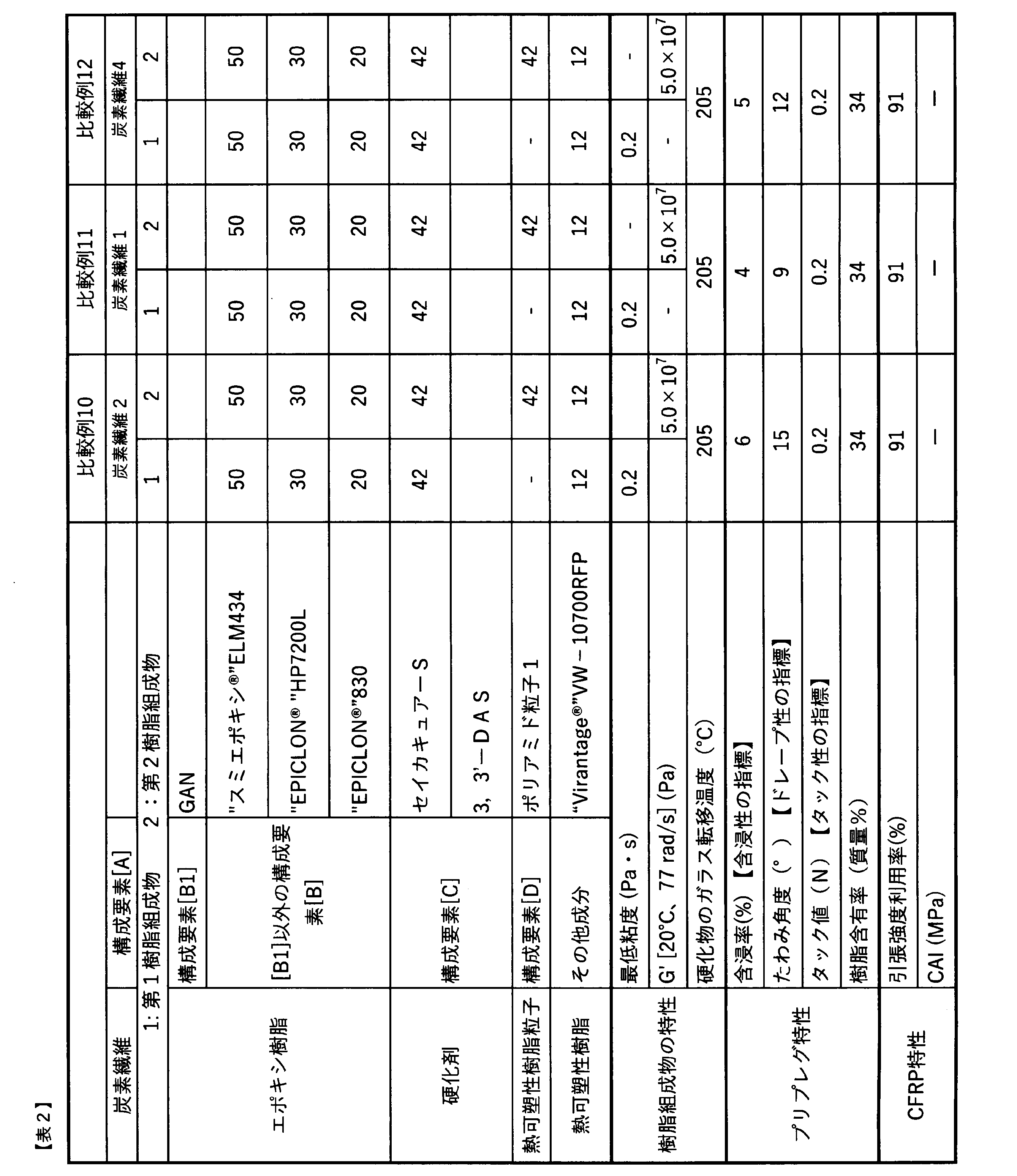

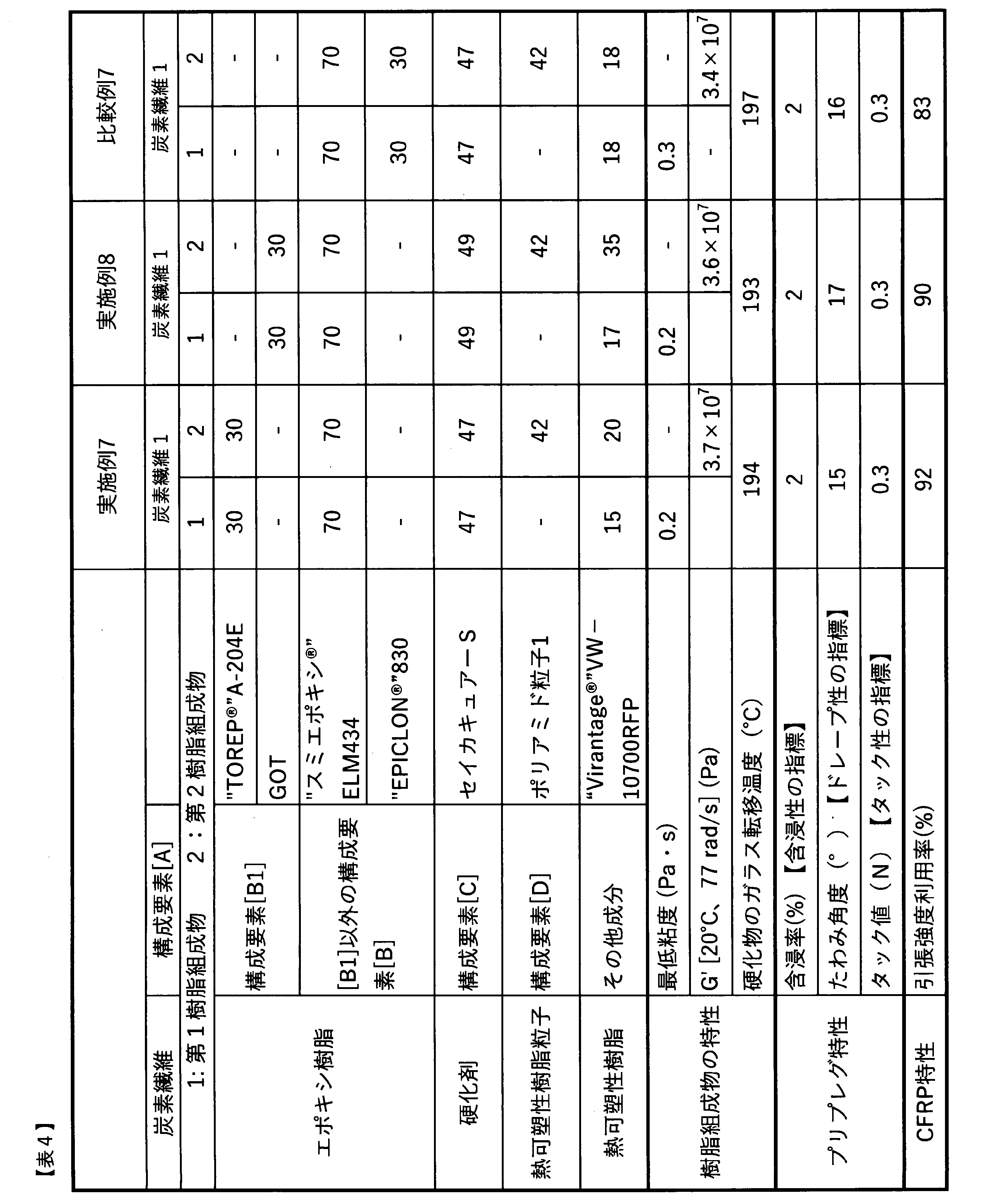
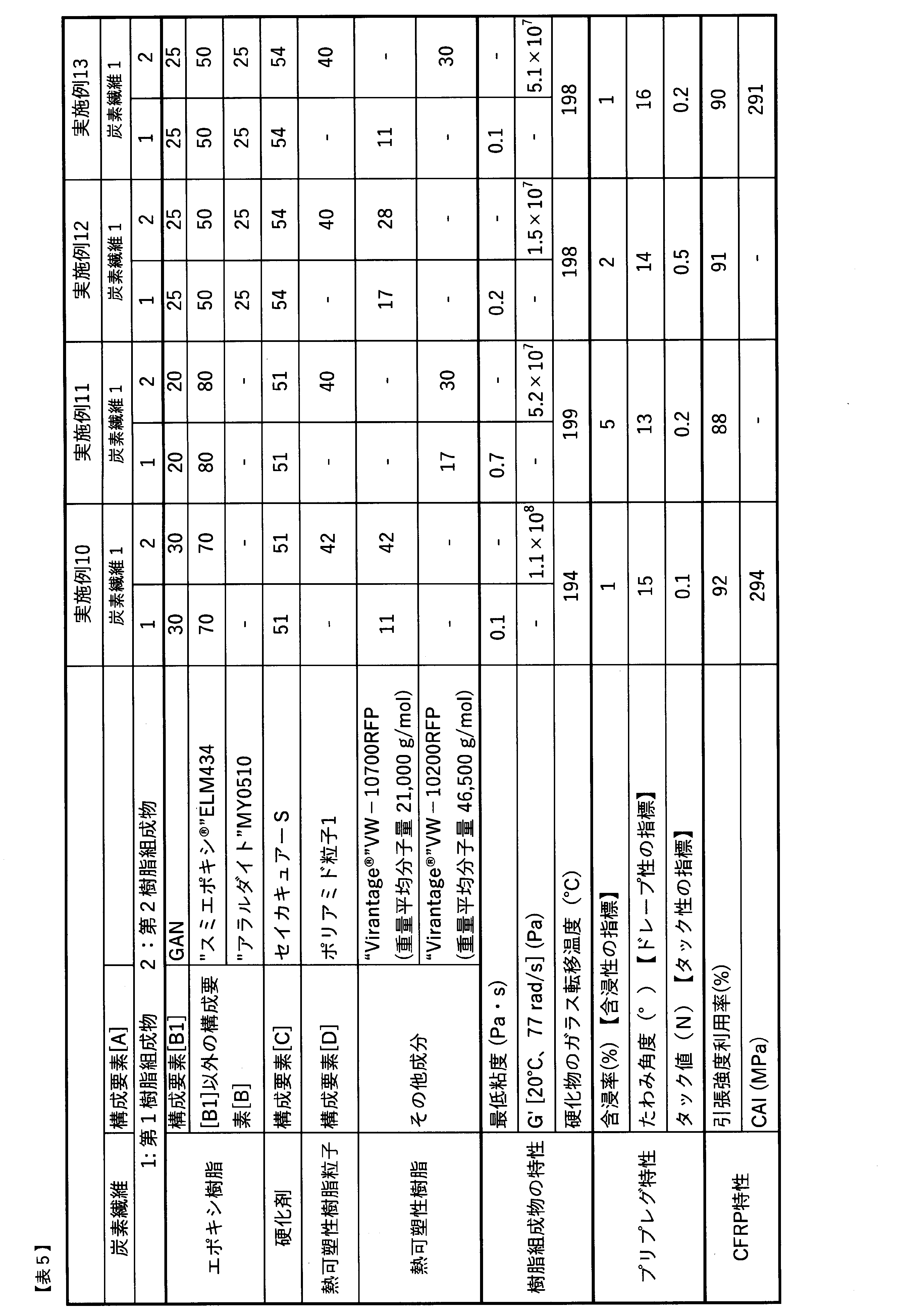
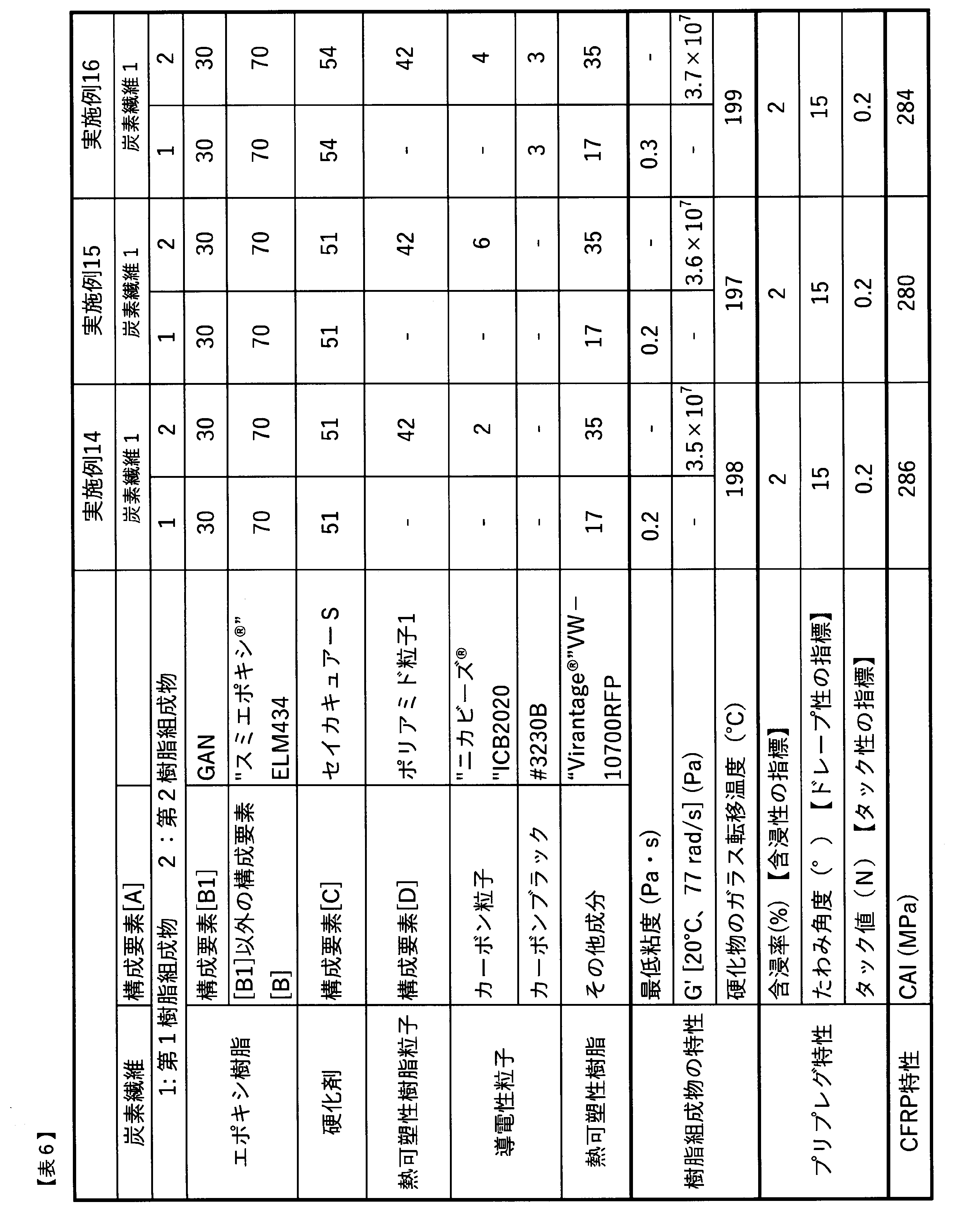
Claims (9)
- 少なくとも下記に示す構成要素[A]~[D]を含むプリプレグであって、
構成要素[A]に構成要素[B]および[C]を含む第1樹脂組成物が含浸されてなる第1層と、第1層の両面に形成された構成要素[B]~[D]を含む第2樹脂組成物からなる第2層とが隣接した構造であり、
構成要素[A]の炭素繊維の平均繊維径は6μm以上9μm以下であり、
構成要素[B]のエポキシ樹脂総量100質量部のうち、2官能アミン型エポキシ樹脂[B1]の含有量が15質量部以上40質量部未満である、プリプレグ:
[A]炭素繊維
[B]エポキシ樹脂
[C]硬化剤
[D]熱可塑性樹脂粒子。 - 構成要素[A]の炭素繊維の平均繊維径が7μm以上である、請求項1に記載のプリプレグ。
- 第1樹脂組成物の最低粘度が1.0Pa・s以下である、請求項1または2に記載のプリプレグ
- 第2樹脂組成物の20℃、77rad/sで測定した貯蔵弾性率G’が2.0×107Pa以上である、請求項1~3に記載のプリプレグ。
- 幅12.7mm、長さ400mmにカットしたプリプレグの一端を水平な机に固定し、机の端からプリプレグが200mmはみ出した状態とした後、10分後のプリプレグのたわみ角が10°以上17°以下の範囲である、請求項1~4のいずれかに記載のプリプレグ。
- プリプレグを硬化させて得られたCFRPの第1層の炭素繊維間の平均距離の変動係数が16%以上50%未満である、請求項1~5のいずれかに記載のプリプレグ。
- 前記第1樹脂組成物および前記第2樹脂組成物を構成する構成要素のうち、構成要素[B]および構成要素[C]のみを配合したガラス転移温度測定用の樹脂組成物を調製し、該ガラス転移温度測定用のエポキシ樹脂組成物を、温度180℃、2時間の条件にて硬化させて得られる樹脂硬化物のガラス転移温度が180℃以上である、請求項1~6のいずれかに記載のプリプレグ。
- 構成要素[A]の炭素繊維の単位面積当たりの炭素繊維質量が250g/m2以上である、請求項1~7のいずれかに記載のプリプレグ。
- 構成要素[B]のエポキシ樹脂総量100質量部に対し、構成要素[E]導電性粒子を1質量部以上含有する、請求項1~8のいずれかに記載のプリプレグ。
Priority Applications (3)
| Application Number | Priority Date | Filing Date | Title |
|---|---|---|---|
| JP2022526357A JP7810105B2 (ja) | 2021-04-26 | 2022-04-25 | プリプレグ |
| US18/281,603 US20240158592A1 (en) | 2021-04-26 | 2022-04-25 | Prepreg |
| EP22795713.1A EP4286461A4 (en) | 2021-04-26 | 2022-04-25 | PREPREG |
Applications Claiming Priority (2)
| Application Number | Priority Date | Filing Date | Title |
|---|---|---|---|
| JP2021073874 | 2021-04-26 | ||
| JP2021-073874 | 2021-04-26 |
Publications (1)
| Publication Number | Publication Date |
|---|---|
| WO2022230800A1 true WO2022230800A1 (ja) | 2022-11-03 |
Family
ID=83847183
Family Applications (1)
| Application Number | Title | Priority Date | Filing Date |
|---|---|---|---|
| PCT/JP2022/018694 Ceased WO2022230800A1 (ja) | 2021-04-26 | 2022-04-25 | プリプレグ |
Country Status (4)
| Country | Link |
|---|---|
| US (1) | US20240158592A1 (ja) |
| EP (1) | EP4286461A4 (ja) |
| JP (1) | JP7810105B2 (ja) |
| WO (1) | WO2022230800A1 (ja) |
Cited By (3)
| Publication number | Priority date | Publication date | Assignee | Title |
|---|---|---|---|---|
| WO2023074733A1 (ja) * | 2021-10-27 | 2023-05-04 | 東レ株式会社 | 炭素繊維強化複合材料 |
| CN116162225A (zh) * | 2023-01-09 | 2023-05-26 | 华东理工大学 | 一种环氧树脂材料及其制备方法和应用 |
| WO2023190319A1 (ja) * | 2022-03-30 | 2023-10-05 | 東レ株式会社 | 炭素繊維強化複合材料およびプリプレグ |
Citations (11)
| Publication number | Priority date | Publication date | Assignee | Title |
|---|---|---|---|---|
| JPH01104624A (ja) | 1987-10-16 | 1989-04-21 | Toray Ind Inc | 樹脂微粒子を用いたプリプレグ |
| JP2000309021A (ja) | 1999-04-27 | 2000-11-07 | Toho Rayon Co Ltd | プリプレグの製造方法 |
| JP2001139662A (ja) | 1999-11-12 | 2001-05-22 | Mitsubishi Rayon Co Ltd | エポキシ樹脂組成物、プリプレグ及びゴルフシャフト |
| WO2012051045A2 (en) | 2010-10-12 | 2012-04-19 | Hexcel Corporation | Improving solvent resistance of epoxy resins toughened with polyethersulfone |
| WO2012124450A1 (ja) | 2011-03-17 | 2012-09-20 | 東レ株式会社 | プリプレグ、プリプレグの製造方法および炭素繊維強化複合材料 |
| JP2016185704A (ja) * | 2014-07-01 | 2016-10-27 | 帝人株式会社 | 繊維強化プラスチックの製造方法 |
| WO2017073483A1 (ja) * | 2015-10-30 | 2017-05-04 | 東レ株式会社 | 繊維強化熱可塑性樹脂成形品および繊維強化熱可塑性樹脂成形材料 |
| WO2018143067A1 (ja) * | 2017-02-02 | 2018-08-09 | 東レ株式会社 | 部分分繊繊維束およびその製造方法、ならびにそれを用いたチョップド繊維束および繊維強化樹脂成形材料 |
| WO2020004421A1 (ja) * | 2018-06-26 | 2020-01-02 | 東レ株式会社 | プリプレグおよびその製造方法、スリットテーププリプレグ、炭素繊維強化複合材料 |
| WO2020003662A1 (ja) * | 2018-06-26 | 2020-01-02 | 東レ株式会社 | プリプレグおよびその製造方法、スリットテーププリプレグ、炭素繊維強化複合材料 |
| JP2020169424A (ja) * | 2019-04-05 | 2020-10-15 | 三井化学株式会社 | 炭素繊維及びこれを含む樹脂組成物 |
Family Cites Families (5)
| Publication number | Priority date | Publication date | Assignee | Title |
|---|---|---|---|---|
| CA2750631A1 (en) * | 2009-03-24 | 2010-09-30 | Toray Industries, Inc. | Epoxy resin composition for fiber-reinforced composite material, prepreg, and fiber-reinforced composite material |
| JP5772012B2 (ja) | 2011-01-27 | 2015-09-02 | 東レ株式会社 | フィラメントワインディング成形用炭素繊維およびその製造方法 |
| KR20160040223A (ko) * | 2013-08-07 | 2016-04-12 | 도레이 카부시키가이샤 | 에폭시 수지 조성물, 프리프레그 및 섬유 강화 복합 재료 |
| WO2015146781A1 (ja) * | 2014-03-24 | 2015-10-01 | 東レ株式会社 | プリプレグおよび繊維強化複合材料 |
| US11760861B2 (en) | 2018-04-16 | 2023-09-19 | Toray Industries, Inc. | Carbon fiber bundle, manufacturing method therefor, prepreg, and carbon fiber-reinforced composite material |
-
2022
- 2022-04-25 JP JP2022526357A patent/JP7810105B2/ja active Active
- 2022-04-25 US US18/281,603 patent/US20240158592A1/en active Pending
- 2022-04-25 WO PCT/JP2022/018694 patent/WO2022230800A1/ja not_active Ceased
- 2022-04-25 EP EP22795713.1A patent/EP4286461A4/en active Pending
Patent Citations (11)
| Publication number | Priority date | Publication date | Assignee | Title |
|---|---|---|---|---|
| JPH01104624A (ja) | 1987-10-16 | 1989-04-21 | Toray Ind Inc | 樹脂微粒子を用いたプリプレグ |
| JP2000309021A (ja) | 1999-04-27 | 2000-11-07 | Toho Rayon Co Ltd | プリプレグの製造方法 |
| JP2001139662A (ja) | 1999-11-12 | 2001-05-22 | Mitsubishi Rayon Co Ltd | エポキシ樹脂組成物、プリプレグ及びゴルフシャフト |
| WO2012051045A2 (en) | 2010-10-12 | 2012-04-19 | Hexcel Corporation | Improving solvent resistance of epoxy resins toughened with polyethersulfone |
| WO2012124450A1 (ja) | 2011-03-17 | 2012-09-20 | 東レ株式会社 | プリプレグ、プリプレグの製造方法および炭素繊維強化複合材料 |
| JP2016185704A (ja) * | 2014-07-01 | 2016-10-27 | 帝人株式会社 | 繊維強化プラスチックの製造方法 |
| WO2017073483A1 (ja) * | 2015-10-30 | 2017-05-04 | 東レ株式会社 | 繊維強化熱可塑性樹脂成形品および繊維強化熱可塑性樹脂成形材料 |
| WO2018143067A1 (ja) * | 2017-02-02 | 2018-08-09 | 東レ株式会社 | 部分分繊繊維束およびその製造方法、ならびにそれを用いたチョップド繊維束および繊維強化樹脂成形材料 |
| WO2020004421A1 (ja) * | 2018-06-26 | 2020-01-02 | 東レ株式会社 | プリプレグおよびその製造方法、スリットテーププリプレグ、炭素繊維強化複合材料 |
| WO2020003662A1 (ja) * | 2018-06-26 | 2020-01-02 | 東レ株式会社 | プリプレグおよびその製造方法、スリットテーププリプレグ、炭素繊維強化複合材料 |
| JP2020169424A (ja) * | 2019-04-05 | 2020-10-15 | 三井化学株式会社 | 炭素繊維及びこれを含む樹脂組成物 |
Non-Patent Citations (1)
| Title |
|---|
| See also references of EP4286461A4 |
Cited By (5)
| Publication number | Priority date | Publication date | Assignee | Title |
|---|---|---|---|---|
| WO2023074733A1 (ja) * | 2021-10-27 | 2023-05-04 | 東レ株式会社 | 炭素繊維強化複合材料 |
| WO2023190319A1 (ja) * | 2022-03-30 | 2023-10-05 | 東レ株式会社 | 炭素繊維強化複合材料およびプリプレグ |
| EP4488320A4 (en) * | 2022-03-30 | 2025-10-15 | Toray Industries | CARBON FIBER REINFORCED PREPREG COMPOSITE MATERIAL |
| CN116162225A (zh) * | 2023-01-09 | 2023-05-26 | 华东理工大学 | 一种环氧树脂材料及其制备方法和应用 |
| CN116162225B (zh) * | 2023-01-09 | 2024-04-02 | 华东理工大学 | 一种环氧树脂材料及其制备方法和应用 |
Also Published As
| Publication number | Publication date |
|---|---|
| EP4286461A4 (en) | 2024-12-25 |
| JPWO2022230800A1 (ja) | 2022-11-03 |
| US20240158592A1 (en) | 2024-05-16 |
| EP4286461A1 (en) | 2023-12-06 |
| JP7810105B2 (ja) | 2026-02-03 |
Similar Documents
| Publication | Publication Date | Title |
|---|---|---|
| KR102081662B1 (ko) | 에폭시 수지 조성물, 프리프레그 및 탄소 섬유 강화 복합 재료 | |
| RU2736820C2 (ru) | Композиция эпоксидной смолы, препрег и композитный материал, армированный углеродным волокном | |
| CA2810589C (en) | Improving solvent resistance of epoxy resins toughened with polyethersulfone | |
| JP6052426B2 (ja) | エポキシ樹脂組成物、樹脂硬化物、プリプレグおよび繊維強化複合材料 | |
| JP7810105B2 (ja) | プリプレグ | |
| US20190210301A1 (en) | Prepreg and production method therefor | |
| JP5723505B2 (ja) | 樹脂組成物、硬化物、プリプレグ、および繊維強化複合材料 | |
| JP5929046B2 (ja) | 炭素繊維織物プリプレグおよび炭素繊維強化複合材料 | |
| WO2014050896A1 (ja) | プリプレグ及びその製造方法 | |
| JPWO2007060833A1 (ja) | 炭素繊維束、プリプレグおよび炭素繊維強化複合材料 | |
| KR20170129098A (ko) | 에폭시 수지 조성물, 프리프레그, 및 탄소섬유 강화 복합재료 | |
| KR20210022664A (ko) | 프리프레그 및 그 제조 방법, 슬릿 테이프 프리프레그, 탄소섬유강화 복합재료 | |
| JP2010059225A (ja) | 炭素繊維強化複合材料用エポキシ樹脂組成物、プリプレグおよび炭素繊維強化複合材料 | |
| KR20200080225A (ko) | 프리프레그 및 섬유 강화 복합재료 | |
| JP2016169381A (ja) | エポキシ樹脂組成物、プリプレグおよび繊維強化複合材料 | |
| JP6555006B2 (ja) | エポキシ樹脂組成物、樹脂硬化物、プリプレグおよび繊維強化複合材料 | |
| CN110191915A (zh) | 预浸料坯及其制造方法、分切带预浸料坯 | |
| JP2010095557A (ja) | プリプレグおよび繊維強化複合材料 | |
| JP6699803B1 (ja) | プリプレグおよびその製造方法、スリットテーププリプレグ、炭素繊維強化複合材料 | |
| JP7596790B2 (ja) | プリプレグ | |
| JP7834981B2 (ja) | 積層体 | |
| JP7415926B2 (ja) | プリプレグおよび繊維強化複合材料 | |
| US12630679B2 (en) | Prepreg | |
| JP2011057907A (ja) | 熱硬化性樹脂組成物とそれを用いたプリプレグ | |
| JP2025139049A (ja) | プリプレグ、繊維強化複合材料、航空機の部材および航空機 |
Legal Events
| Date | Code | Title | Description |
|---|---|---|---|
| ENP | Entry into the national phase |
Ref document number: 2022526357 Country of ref document: JP Kind code of ref document: A |
|
| 121 | Ep: the epo has been informed by wipo that ep was designated in this application |
Ref document number: 22795713 Country of ref document: EP Kind code of ref document: A1 |
|
| WWE | Wipo information: entry into national phase |
Ref document number: 2022795713 Country of ref document: EP |
|
| ENP | Entry into the national phase |
Ref document number: 2022795713 Country of ref document: EP Effective date: 20230829 |
|
| WWE | Wipo information: entry into national phase |
Ref document number: 18281603 Country of ref document: US |
|
| NENP | Non-entry into the national phase |
Ref country code: DE |