WO2022244143A1 - Appareil de travail robotisé - Google Patents
Appareil de travail robotisé Download PDFInfo
- Publication number
- WO2022244143A1 WO2022244143A1 PCT/JP2021/018991 JP2021018991W WO2022244143A1 WO 2022244143 A1 WO2022244143 A1 WO 2022244143A1 JP 2021018991 W JP2021018991 W JP 2021018991W WO 2022244143 A1 WO2022244143 A1 WO 2022244143A1
- Authority
- WO
- WIPO (PCT)
- Prior art keywords
- area
- work
- robot
- working
- travel route
- Prior art date
- Legal status (The legal status is an assumption and is not a legal conclusion. Google has not performed a legal analysis and makes no representation as to the accuracy of the status listed.)
- Ceased
Links
Images





Classifications
-
- G—PHYSICS
- G05—CONTROLLING; REGULATING
- G05D—SYSTEMS FOR CONTROLLING OR REGULATING NON-ELECTRIC VARIABLES
- G05D1/00—Control of position, course, altitude or attitude of land, water, air or space vehicles, e.g. using automatic pilots
- G05D1/60—Intended control result
- G05D1/648—Performing a task within a working area or space, e.g. cleaning
- G05D1/6484—Performing a task within a working area or space, e.g. cleaning by taking into account parameters or characteristics of the working area or space, e.g. size or shape
-
- G—PHYSICS
- G05—CONTROLLING; REGULATING
- G05D—SYSTEMS FOR CONTROLLING OR REGULATING NON-ELECTRIC VARIABLES
- G05D1/00—Control of position, course, altitude or attitude of land, water, air or space vehicles, e.g. using automatic pilots
- G05D1/02—Control of position or course in two dimensions
- G05D1/021—Control of position or course in two dimensions specially adapted to land vehicles
- G05D1/0212—Control of position or course in two dimensions specially adapted to land vehicles with means for defining a desired trajectory
-
- G—PHYSICS
- G05—CONTROLLING; REGULATING
- G05D—SYSTEMS FOR CONTROLLING OR REGULATING NON-ELECTRIC VARIABLES
- G05D1/00—Control of position, course, altitude or attitude of land, water, air or space vehicles, e.g. using automatic pilots
- G05D1/0011—Control of position, course, altitude or attitude of land, water, air or space vehicles, e.g. using automatic pilots associated with a remote control arrangement
-
- G—PHYSICS
- G05—CONTROLLING; REGULATING
- G05D—SYSTEMS FOR CONTROLLING OR REGULATING NON-ELECTRIC VARIABLES
- G05D1/00—Control of position, course, altitude or attitude of land, water, air or space vehicles, e.g. using automatic pilots
- G05D1/20—Control system inputs
- G05D1/22—Command input arrangements
- G05D1/229—Command input data, e.g. waypoints
- G05D1/2297—Command input data, e.g. waypoints positional data taught by the user, e.g. paths
-
- A—HUMAN NECESSITIES
- A01—AGRICULTURE; FORESTRY; ANIMAL HUSBANDRY; HUNTING; TRAPPING; FISHING
- A01D—HARVESTING; MOWING
- A01D2101/00—Lawn-mowers
-
- A—HUMAN NECESSITIES
- A01—AGRICULTURE; FORESTRY; ANIMAL HUSBANDRY; HUNTING; TRAPPING; FISHING
- A01D—HARVESTING; MOWING
- A01D34/00—Mowers; Mowing apparatus of harvesters
- A01D34/006—Control or measuring arrangements
- A01D34/008—Control or measuring arrangements for automated or remotely controlled operation
-
- G—PHYSICS
- G05—CONTROLLING; REGULATING
- G05D—SYSTEMS FOR CONTROLLING OR REGULATING NON-ELECTRIC VARIABLES
- G05D2105/00—Specific applications of the controlled vehicles
- G05D2105/15—Specific applications of the controlled vehicles for harvesting, sowing or mowing in agriculture or forestry
-
- G—PHYSICS
- G05—CONTROLLING; REGULATING
- G05D—SYSTEMS FOR CONTROLLING OR REGULATING NON-ELECTRIC VARIABLES
- G05D2107/00—Specific environments of the controlled vehicles
- G05D2107/20—Land use
- G05D2107/23—Gardens or lawns
-
- G—PHYSICS
- G05—CONTROLLING; REGULATING
- G05D—SYSTEMS FOR CONTROLLING OR REGULATING NON-ELECTRIC VARIABLES
- G05D2109/00—Types of controlled vehicles
- G05D2109/10—Land vehicles
Definitions
- the present invention relates to a robot working device that performs work while autonomously traveling on the field.
- Patent Document 1 Conventionally, working robots that perform tasks such as mowing while autonomously traveling within a work area are known (see Patent Document 1 below).
- a user designates a virtual boundary line for a work area, divides the work area into a plurality of areas by the designated virtual boundary line, and assigns a priority work area to each of the divided multiple areas. etc. is being set.
- the work area is once divided into a plurality of areas, and the user assigns meanings such as priority to the divided multiple areas. It is made to do. This is because the input of one virtual boundary line can divide the work area, but the divided area cannot be specified. For this reason, for example, even if it is attempted to set an area in which priority work is to be performed individually for a part of the work area, a process of dividing the area by the boundary line and a process of assigning meaning to the divided area will occur, and the priority work will be quickly performed. There was a problem that the area could not be set.
- the division boundary to be set will also be complicated. There was also the problem that it took a long time to set up.
- a work area with a complicated outline is divided by a virtual boundary line, a part of the complex outline of the original work area remains in the outline of the divided area. There was a problem that the work area could not be divided easily.
- the object of the present invention is to deal with such problems. In other words, it is to be possible to quickly set an individual area assigned a meaning to a work area, and to quickly and easily partition a work area having a desired shape in a work area having a complicated outer shape. , etc. are the subject of the present invention.
- a robot working device comprising a working robot that performs work while autonomously traveling within a set working area, comprising a control unit for controlling the operation of the working robot, wherein the control unit partitions and sets the working area.
- a robot working device comprising: a work area setting unit for setting a work area, wherein the work area setting unit sets an individual enclosed area that overlaps an existing work area.
- the operation of setting the enclosing area divides the area into an enclosed area and an unenclosed area.
- the area to be specified is determined uniquely, so that the individual area assigned meaning to the set work area can be quickly set.
- the work of the desired shape can be performed quickly and easily by a single operation of setting the surrounding area. Since the area can be set, it is possible to construct a human interface that makes use of the operator's intuition for screen input.
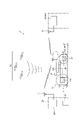
- FIG. 2 is an explanatory diagram showing a configuration example of a robot working device (an example in which a working robot performs mowing work);
- FIG. 2 is an explanatory diagram showing a configuration example of a robot working device (an example in which a working robot performs collection work);
- Explanatory drawing which showed the system configuration
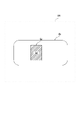
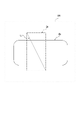
- FIG. 4 is an explanatory diagram showing an example of setting an enclosing area by a work area setting unit;
- FIG. 4 is an explanatory diagram showing an example of setting an enclosing area by a work area setting unit;
- FIG. 4 is an explanatory diagram showing an example of setting an enclosing area by a work area setting unit;
- FIG. 4 is an explanatory diagram showing an example of setting an enclosing area by a work area setting unit;
- FIG. 4 is an explanatory diagram showing an example of setting an enclosing
- FIG. 4 is an explanatory diagram showing an example of setting an enclosing area by a work area setting unit;
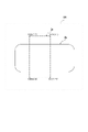
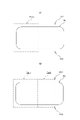
- FIG. 4 is an explanatory diagram showing an example of setting an enclosing area by a work area setting unit; Explanatory diagrams showing examples of setting adjacent enclosing areas by the work area setting unit ((a) shows the state of point coordinate input before setting, and (b) shows the second enclosing area set by the point coordinates. ing.).
- FIG. 4 shows an explanatory diagram showing an example of setting an enclosing area by a work area setting unit
- FIG. 4 is an explanatory diagram showing an example of setting an enclosing area by a work area setting unit
- Explanatory diagrams showing examples of setting adjacent enclosing areas by the work area setting unit ((a) shows the state of point coordinate input before setting, and (b) shows the second enclosing area set by the point coordinates. ing.).
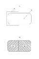
- FIG. 4 is an explanatory diagram showing an example of setting adjacent enclosing areas having overlapping areas;
- An explanatory view showing a setting example of setting a non-work area along with setting of a small section ((a) is a state in which an enclosing area Ea is set for a work area Wa, (b) is a work area with a small section Sd and A state in which the non-work area Nw is set.).
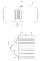
- Explanatory diagram showing an example of setting the traveling route by the traveling route setting unit ((a) is an example of setting the traveling route in the small section and the traveling route between the small section and the base, and (b) is the past traveling route example of different route settings).
- the robot working device 1 includes a working robot 10 that works on the field F.
- the work robot 10 is equipped with a work tool, which will be described later, for performing work in the field F, and performs work while autonomously traveling on the field F.
- the work performed by the work robot 10 is not particularly limited, but includes, for example, mowing work, collection work, and cleaning work.
- the robot working device 1 is provided with a base 20 for the field F.
- Base 20 may be provided inside field F or outside field F as shown.
- the base 20 is, for example, a charging base for the electric work robot 10, and also serves as a collection target discharge place when the work robot 10 performs collection work.
- the robot working device 1 is equipped with a management device 30 as necessary.
- the management device 30 is for remotely controlling the working robot 10, and can be omitted when the working robot 10 operates by its own control unit.
- the management device 30 may be provided within the field F or may be provided outside the field F.
- the robot work device 1 sets a work area Wa for the work robot 10 on the field F.
- the work robot 10 performs work while autonomously traveling within the set work area Wa. As shown in FIG. 1, when a plurality of work areas Wa are set, the work robot 10 moves to another work area Wa after completing work in one work area Wa.
- the work area Wa here can be set in the system as a virtual area based on position information, but a physical area may be set in the field F using wires, markers, beacons, or the like.
- the work robot 10 travels along the set travel route Rw or randomly travels in an arbitrary direction to perform work while traveling throughout the work area Wa.
- the travel route Rw set in the work area Wa is not limited to a linear route as shown in the drawing, and any route can be set.
- FIGS. 2 and 3 show configuration examples of the robot working device 1.
- the working robot 10 includes a traveling portion 11 having wheels for traveling on the field F, a work tool 12 for performing work on the field F, a traveling drive portion (motor) 11A for driving the traveling portion 11, and a working tool 12. , a control unit (CPU) 10A for controlling these operations, a battery 14 as a power source for the working robot 10, and the like.
- CPU central processing unit
- the traveling unit 11 has left and right traveling wheels, and the working robot 10 can move forward and backward, turn left and right, and steer in any direction under the control of the traveling drive unit 11A that drives each traveling wheel independently. It's becoming
- the work tool 12 provided in the work robot 10 is a blade device 12S for mowing the field F in the example shown in FIG.
- the blade device 12S mows the grass on the field F by rotationally driving or reciprocating linearly driven by the work driving part 12A.
- the work robot 10 also includes a position detection unit 16 for autonomous travel.
- the position detection unit 16 is, for example, a GNSS sensor that receives radio signals emitted from satellites 100 in a satellite positioning system (GNSS: Global Navigation Satellite System) such as GPS.
- GNSS Global Navigation Satellite System
- a receiving device or the like that receives radio waves emitted by a beacon or the like can be used.
- a plurality of position detection units 16 may be provided.
- the autonomous travel of the working robot 10 is such that the detected position of the position detector 16 is input to the controller 10A, and the position of the set travel route and the detected position match, or the detected position is within the set work area Wa. is included by the control unit 10A controlling the traveling drive unit 11A.
- the working robot 10 is equipped with a communication unit 17 that transmits and receives information to and from other devices as necessary.
- a partner with which the working robot 10 transmits and receives information via the communication unit 17 is, for example, the management device 30 installed in a facility or the like, and another example is the control unit 20A provided in the base 20.
- the working robot 10 can transmit and receive information to and from other working robots 10 deployed on the field F.
- the management device 30 is a computer installed in a facility or a server connected to a network, and includes a communication section 31 for transmitting and receiving information to and from the communication section 17 of the working robot 10 .
- the base 20 includes a control unit 20A having a communication unit 21 that transmits and receives information to and from the communication unit 17 of the working robot 10, and a charging device 22 that charges the battery . Communication between the communication units 17, 21, 31 can be performed directly or via a network. When the control unit 10A of the work robot 10 executes the control processing alone, the communication units 17, 21, 31 and the management device 30 can be omitted. 20 A of control parts of the base 20 can also serve as the management apparatus 30. FIG.
- FIG. 3 shows an example in which the work robot 10 is equipped with a collection device 12P as the work tool 12 that picks up the objects O to be collected and stores them in the storage unit 13.
- the collection device 12P and the storage unit 13 are provided with a weighing unit 15 that measures the amount of the collected objects O that have been collected.
- the weighing unit 15 includes a counter that counts the number of objects O picked up by the collecting device 12P, a weighing scale that measures the number or weight of the objects O stored in the storage unit 13, and the work load of the work tool 12.
- a load measuring instrument or the like can be used to measure the Information weighed by the weighing unit 15 is input to the control unit 10A.
- Other configurations of the working robot 10 shown in FIG. 3 are the same as the example shown in FIG.
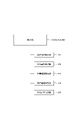
- FIG. 4 shows a system configuration example of the robot operating device 1.
- the control unit 10A of the work robot 10 transmits and receives information via the communication unit 17 as described above, and the control unit (CPU) 30A of the management device 30 transmits and receives information via the communication unit 31.
- a control unit (CPU) 20A of the base 20 transmits and receives information via a communication unit 21.
- FIG. 10A The control unit 10A of the work robot 10 transmits and receives information via the communication unit 17 as described above, and the control unit (CPU) 30A of the management device 30 transmits and receives information via the communication unit 31.
- a control unit (CPU) 20A of the base 20 transmits and receives information via a communication unit 21.
- the control units 10A, 20A, and 30A are provided with clock units 50, 51, and 52 such as real-time clocks that clock and output time, respectively, and memories 60, 61, and 60 that store information and programs. 62 each. Further, the control units 10A, 20A, and 30A constitute one control unit U integrated by information exchange between the communication units 17, 21, and 31, and the functions provided by one of the control units 10A, 20A, and 30A are Other control units 10A, 20A, and 30A can be substituted.
- the control unit 10A of the work robot 10 receives work instruction information (information on the existing work schedule, work area, travel route, etc.) from the setting input unit 19, and receives information from the work state detection unit 10T. Information about the current position of the work robot 10 is input from the detector 16 , and information about the remaining battery level is input from the battery 14 . Based on the input information, the control section 10A controls the traveling drive section 11A and the work drive section 12A to perform the work of the working robot 10 according to the input work instruction information.
- work instruction information information on the existing work schedule, work area, travel route, etc.
- the work state detection unit 10T detects the drive state such as the load of the blade. Information about the amount of collection objects O collected is detected.
- Charging progress information and the like are input from a charging device 22 that charges the battery 14 of the work robot 10 to the control unit 20A provided at the base 20 .
- the control unit 30A of the management device 30 receives from the setting input unit 32 work instruction information (work schedule, work area, travel route information, etc.) and management facility information (business hours, users, places of use, field conditions, etc.). , plant growth information in the field, the supply amount of collection objects O, events at management facilities and their times, etc.) are input.
- work instruction information work schedule, work area, travel route information, etc.
- management facility information business hours, users, places of use, field conditions, etc.
- the control performed by the control units U (10A, 20A, 30A) of the robot working device 1 includes a traveling operation control unit P1 that performs autonomous traveling control of the traveling unit 11 (traveling drive unit 11A), A work motion control unit P2 that controls the motion of the work unit 12 (work drive unit 12A), a work area setting unit P3 that partitions and sets the work area of the work robot 10, and a travel route setting unit P4 that sets the travel route of the work robot 10. , a work content setting unit P5 for setting work content (at least one of work time, work frequency, work order, and work load) within the set work area.
- the traveling motion control unit P1, the work motion control unit P2, the work area setting unit P3, the travel route setting unit P4, and the work content setting unit P5 control the operation of the CPU of the control unit U (10A, 20A, 30A). It's a program.
- the work area setting part P3 uses the display screen 200, which is an input interface for the setting input parts 19 and 32 described above, to set the work area based on the input operation.
- the display screen 200 corresponds to the entire field F or a partial area within the field F
- the plane coordinate position within the display screen 200 is a position within the field F or within a partial area within the field F. corresponds to For example, when the work area Wa, which is a partial area within the field F, is displayed on the display screen 200, the plane coordinates including the work area Wa are the coordinates on the display screen 200.
- the work area setting part P3 displays the work area Wa on the display screen 200 based on the position information of the set work area Wa.
- the set work area Wa is a physical area partitioned by wires or the like
- the work area Wa is displayed on the display screen 200 by acquiring and inputting the position information of the wire or the like. be done.
- the work area Wa is a virtual area based on the position information
- the work area Wa is displayed on the display screen 200 according to the position information.
- the work area setting part P3 sets an individual enclosing area Ea overlapping the work area Wa for the work area Wa displayed on the display screen 200 .
- the enclosing area Ea is drawn and input on the display screen 200 using the drawing function of the work area setting unit P3.
- a well-known user interface such as mouse input or touch input is used as an operation input means at that time, and as shown in FIG. can.
- the setting of the enclosing area Ea by the plane figure is effective especially when the desired enclosing area Ea corresponds to the plane figure, and can be easily set by one operation.
- the planar figure to be input at this time is not limited to a rectangular figure as shown in the drawing, but may be a circle, an ellipse, or other polygons as appropriate.
- the work area setting unit P3 sets the overlapping portion between the work area Wa and the enclosing area Ea as the small section Sd of the work area Wa.
- part of the enclosing area Ea is set outside the work area Wa, but as shown in FIG. 7, the enclosing area Ea can also be set inside the work area Wa.
- the enclosing area Ea and the small section Sd are the same area.
- the enclosing area Ea is set by inputting drawing of a plane figure using the drawing function.
- FIG. can be set by multiple point coordinates.
- a well-known user interface is also used at this time, and point coordinates D1 (X1, Y1), D2 (X2, Y2), D3 (X3, Y3), D4 (X4, Y4), etc.
- the point coordinates are input on the input screen 200, and an enclosing area Ea is set so as to enclose the point coordinates with a straight line or the like.
- point coordinates are input outside the work area Wa, but point coordinates may be input inside the work area Wa.
- the enclosed area Ea can be set by a line Ls input to the input screen 200, as shown in FIG. A well-known user interface is also used at this time, and as shown in FIG. 9, by inputting a line Ls, the enclosing area Ea can be set by a plane figure having the line Ls as a diagonal line.
- a drawing editing function is provided in the work area setting section P3, and a planar figure or the like once input is enlarged, reduced, rotated, or transformed to appropriately set the enclosing area to a desired shape and area. Ea may be obtained.
- a plurality of surrounding areas Ea can be set. As shown in FIG. 6, after setting one enclosing area Ea individually, another enclosing area Ea can be set individually, but after setting one enclosing area (first area) Ea, Another surrounding area Ea can be set adjacently.
- a second enclosing area Ea(2) adjacent to the first enclosing area Ea(1) can be set.
- one side of the second enclosing area Ea(2) is a common side with one side of the first enclosing area Ea(1).
- the second enclosing area Es(2) similarly adjacent to the first enclosing area Ea(1) can be determined with only one point coordinate. can be set.
- a second enclosing area Ea(2) having an overlapping area Ea(3) partially overlapping the first enclosing area Ea(1) can also be set.
- a desired overlap area Ea(3) can be formed by inputting an arbitrary numerical value and unit as the width to be overlapped.
- the work area setting unit P3 sets a small section Sd of the work area as shown in FIG. 12(b) by setting an enclosing area Ea for the work area Wa as shown in FIG. 12(a). Further, by inputting the point coordinates D outside the enclosing area Ea within the work area Wa, the work area Wa including the point coordinates D is set as the non-work section Nw. At this time, even if the point coordinate D is not input, the entire outer side of the enclosing area Ea may be set as the non-work section.
- the enclosing area Ea is set as the small section Sd of the work area, and the entire outside of the enclosing area Ea is set as the non-work section Nw.
- the entire area outside Ea may be set as a small section Nw of the work area.
- the work content of each section can be changed by operating a button on the screen or a button on the input section. By doing so, it is possible to instantly set an area with meaning in the section inside the work area Wa and outside the enclosing area Ea.
- the sections on the screen can be made identifiable by color or pattern according to the work content of the work robot in the section set by the enclosing area Ea. It may be identified by the color scheme or pattern of the entire partitioned area, or may be identified by the color or line type of the boundary line.
- the travel route setting unit P4 sets the work travel route Rw in the small section Sd.
- the travel route Rw may be, for example, a parallel straight round-trip route as shown in FIG. 13(a), or may be set to another route such as a circular route.
- the traveling route setting section P4 sets a traveling route R1 from the base 20 toward the work start point for that section.
- a travel route R2 from the work end point of section Sd to base 20 is set.
- the travel route setting unit P4 sets the travel route each time so that at least a part of the travel route differs from the previously set travel route.
- the travel routes Rw′, R1′, and R2′ indicated by dashed lines are set so as not to overlap each other.
- the subsection Sd obtained by setting the enclosing area Ea for the work area Wa can be a meaningful area, such as setting a priority work area, for example. At this time, it is possible to set individual surrounding areas Ea without dividing the work area Wa into a plurality of sections, and immediately set a priority work area or the like in the obtained small section Sd. Individual regions that are meaningful can be set quickly.
- the work area setting unit P3 described above can communicate with the control unit U described above, and can be provided in an external device that can be operated by the user.
- the external device in this case is, for example, a personal computer, a mobile phone terminal, or the like having an input unit such as a mouse and buttons and a display unit such as a screen.
- the input unit of the external device may also be used as the display unit, such as a smartphone or a tablet terminal.
- the work content setting unit P5 sets the work content in the enclosing area Ea and the work content in areas other than the enclosing area Ea.
- the work content at least one of work time, work frequency, work order, and work load
- the work content in the enclosed area Ea can be set to be different from the work content in areas other than the enclosed area Ea.
Landscapes
- Engineering & Computer Science (AREA)
- Aviation & Aerospace Engineering (AREA)
- Radar, Positioning & Navigation (AREA)
- Remote Sensing (AREA)
- Physics & Mathematics (AREA)
- General Physics & Mathematics (AREA)
- Automation & Control Theory (AREA)
- Life Sciences & Earth Sciences (AREA)
- Environmental Sciences (AREA)
- Control Of Position, Course, Altitude, Or Attitude Of Moving Bodies (AREA)
Abstract
Priority Applications (4)
| Application Number | Priority Date | Filing Date | Title |
|---|---|---|---|
| EP21940759.0A EP4336296A4 (fr) | 2021-05-19 | 2021-05-19 | Appareil de travail robotisé |
| PCT/JP2021/018991 WO2022244143A1 (fr) | 2021-05-19 | 2021-05-19 | Appareil de travail robotisé |
| JP2023522079A JPWO2022244143A1 (fr) | 2021-05-19 | 2021-05-19 | |
| US18/511,100 US20240085912A1 (en) | 2021-05-19 | 2023-11-16 | Robotic working apparatus |
Applications Claiming Priority (1)
| Application Number | Priority Date | Filing Date | Title |
|---|---|---|---|
| PCT/JP2021/018991 WO2022244143A1 (fr) | 2021-05-19 | 2021-05-19 | Appareil de travail robotisé |
Related Child Applications (1)
| Application Number | Title | Priority Date | Filing Date |
|---|---|---|---|
| US18/511,100 Continuation US20240085912A1 (en) | 2021-05-19 | 2023-11-16 | Robotic working apparatus |
Publications (1)
| Publication Number | Publication Date |
|---|---|
| WO2022244143A1 true WO2022244143A1 (fr) | 2022-11-24 |
Family
ID=84141419
Family Applications (1)
| Application Number | Title | Priority Date | Filing Date |
|---|---|---|---|
| PCT/JP2021/018991 Ceased WO2022244143A1 (fr) | 2021-05-19 | 2021-05-19 | Appareil de travail robotisé |
Country Status (4)
| Country | Link |
|---|---|
| US (1) | US20240085912A1 (fr) |
| EP (1) | EP4336296A4 (fr) |
| JP (1) | JPWO2022244143A1 (fr) |
| WO (1) | WO2022244143A1 (fr) |
Citations (7)
| Publication number | Priority date | Publication date | Assignee | Title |
|---|---|---|---|---|
| JP2011048565A (ja) * | 2009-08-26 | 2011-03-10 | Ihi Aerospace Co Ltd | 半自律型無人車両の遠隔操縦システム |
| WO2014141351A1 (fr) * | 2013-03-11 | 2014-09-18 | 株式会社 日立製作所 | Dispositif de commande autonome |
| JP5973608B1 (ja) | 2015-03-27 | 2016-08-23 | 本田技研工業株式会社 | 無人作業車の制御装置 |
| JP2017224362A (ja) * | 2017-10-02 | 2017-12-21 | シャープ株式会社 | 自走式電子機器、および自走式電子機器の制御方法 |
| JP2018169787A (ja) * | 2017-03-29 | 2018-11-01 | パナソニック株式会社 | 自律型モビリティシステムおよび自律型モビリティの制御方法 |
| JP2018196514A (ja) * | 2017-05-23 | 2018-12-13 | 東芝ライフスタイル株式会社 | 電気掃除機 |
| JP2018197928A (ja) * | 2017-05-23 | 2018-12-13 | 東芝ライフスタイル株式会社 | 電気掃除機 |
Family Cites Families (17)
| Publication number | Priority date | Publication date | Assignee | Title |
|---|---|---|---|---|
| JP2005078415A (ja) * | 2003-09-01 | 2005-03-24 | Fuji Heavy Ind Ltd | 走行経路生成方法、走行経路生成装置およびコンピュータプログラム |
| GB2445963A (en) * | 2007-01-26 | 2008-07-30 | Mcmurtry Ltd | Ball collection apparatus |
| JP5158808B2 (ja) * | 2009-02-23 | 2013-03-06 | 独立行政法人科学技術振興機構 | ロボット制御システム及びロボット制御方法 |
| EP2939508B1 (fr) * | 2012-12-28 | 2021-05-19 | Positec Power Tools (Suzhou) Co., Ltd | Système de tondeuse automatique |
| JP6636260B2 (ja) * | 2015-04-21 | 2020-01-29 | Cyberdyne株式会社 | 自律移動体の走行経路教示システムおよび走行経路教示方法 |
| JP6419642B2 (ja) * | 2015-05-15 | 2018-11-07 | 日立建機株式会社 | 管制サーバ及び交通管制システム |
| EP4276645A3 (fr) * | 2016-12-15 | 2024-01-10 | Positec Power Tools (Suzhou) Co., Ltd. | Méthode de détection d'état pour système de travail automatique et station mobile |
| JP2017221222A (ja) * | 2017-09-13 | 2017-12-21 | ヤンマー株式会社 | 自律走行作業システム |
| JP7100450B2 (ja) * | 2017-12-26 | 2022-07-13 | アマノ株式会社 | 操作装置、情報作成方法、プログラムおよび自律走行作業装置 |
| GB2580991B (en) * | 2019-07-22 | 2021-05-05 | Kingdom Tech Ltd | Robotic lawn mower control |
| EP4006681B1 (fr) * | 2019-07-23 | 2024-10-16 | Honda Motor Co., Ltd. | Machine de travail autonome, procédé de commande de machine de travail autonome |
| KR102295824B1 (ko) * | 2019-12-06 | 2021-08-31 | 엘지전자 주식회사 | 잔디깎기 로봇의 지도 생성방법 |
| JP6857267B2 (ja) * | 2020-02-23 | 2021-04-14 | ジオサーフ株式会社 | 圃場ガイダンスシステム及び圃場ガイダンス方法並びにソフトウェア及びソフトウェアを格納した記憶媒体 |
| CN111854744A (zh) * | 2020-07-17 | 2020-10-30 | 无锡卡尔曼导航技术有限公司 | 一种gnss单点定位和惯性导航割草机的运行方法 |
| JP2022068643A (ja) * | 2020-10-22 | 2022-05-10 | 本田技研工業株式会社 | 自律作業システム |
| JP7640189B2 (ja) * | 2020-10-28 | 2025-03-05 | アマノ株式会社 | 自律走行作業装置、作業プランの修正方法及びプログラム |
| JP7667399B2 (ja) * | 2021-03-09 | 2025-04-23 | 日本電気株式会社 | システム、方法、およびプログラム |
-
2021
- 2021-05-19 EP EP21940759.0A patent/EP4336296A4/fr active Pending
- 2021-05-19 WO PCT/JP2021/018991 patent/WO2022244143A1/fr not_active Ceased
- 2021-05-19 JP JP2023522079A patent/JPWO2022244143A1/ja active Pending
-
2023
- 2023-11-16 US US18/511,100 patent/US20240085912A1/en active Pending
Patent Citations (7)
| Publication number | Priority date | Publication date | Assignee | Title |
|---|---|---|---|---|
| JP2011048565A (ja) * | 2009-08-26 | 2011-03-10 | Ihi Aerospace Co Ltd | 半自律型無人車両の遠隔操縦システム |
| WO2014141351A1 (fr) * | 2013-03-11 | 2014-09-18 | 株式会社 日立製作所 | Dispositif de commande autonome |
| JP5973608B1 (ja) | 2015-03-27 | 2016-08-23 | 本田技研工業株式会社 | 無人作業車の制御装置 |
| JP2018169787A (ja) * | 2017-03-29 | 2018-11-01 | パナソニック株式会社 | 自律型モビリティシステムおよび自律型モビリティの制御方法 |
| JP2018196514A (ja) * | 2017-05-23 | 2018-12-13 | 東芝ライフスタイル株式会社 | 電気掃除機 |
| JP2018197928A (ja) * | 2017-05-23 | 2018-12-13 | 東芝ライフスタイル株式会社 | 電気掃除機 |
| JP2017224362A (ja) * | 2017-10-02 | 2017-12-21 | シャープ株式会社 | 自走式電子機器、および自走式電子機器の制御方法 |
Also Published As
| Publication number | Publication date |
|---|---|
| EP4336296A4 (fr) | 2025-03-05 |
| EP4336296A1 (fr) | 2024-03-13 |
| US20240085912A1 (en) | 2024-03-14 |
| JPWO2022244143A1 (fr) | 2022-11-24 |
Similar Documents
| Publication | Publication Date | Title |
|---|---|---|
| CN113115621B (zh) | 智能割草系统及其自主建图方法 | |
| CN114815814B (zh) | 自移动设备的作业方法、计算机设备及存储介质 | |
| CN109240284B (zh) | 一种无人驾驶农机的自主路径规划方法及装置 | |
| RU2701892C2 (ru) | Система планирования разработки поля, способ планирования разработки поля и сельскохозяйственная рабочая машина с такой системой планирования | |
| EP3999255B1 (fr) | Système pour l'exécution d'une tâche désignée | |
| EP4260153B1 (fr) | Fonctionnement amélioré pour outil de travail robotisé | |
| CN110320915A (zh) | 具有自动建图和路径规划功能的作业平台及其控制方法 | |
| WO2022102365A1 (fr) | Système, procédé, et programme de déplacement autonome | |
| JP2019082846A (ja) | 協調作業システム | |
| JP2014038437A (ja) | 対地作業管理システム及びそのシステムで用いられる対地作業機 | |
| CN114815711A (zh) | 一种山地智能运输系统及其控制管理方法 | |
| JP2019109163A (ja) | 作業車のための衛星測位システム | |
| WO2022244143A1 (fr) | Appareil de travail robotisé | |
| US12575486B2 (en) | Robotic working apparatus | |
| CN119200621A (zh) | 无人作业设备的作业方法、系统及装置 | |
| CN116679697B (zh) | 一种割草机控制方法、割草机系统及割草机 | |
| KR20240006447A (ko) | 경로 생성 방법, 경로 생성 시스템, 및 경로 생성 프로그램 | |
| CN116889149A (zh) | 控制装置及作业车辆 | |
| HK40081540A (en) | Robotic working apparatus | |
| CN116521802B (zh) | 农机路径管理方法、电子设备及存储介质 | |
| CN112034850A (zh) | 一种实现农场无人化生产的方法 | |
| WO2023032007A1 (fr) | Système de gestion de robot de travail | |
| CN113867329A (zh) | 一种确定行进路线的方法、设备及存储介质 | |
| HK40081540B (en) | Robotic working apparatus | |
| CN114679951B (zh) | 自驱动设备系统 |
Legal Events
| Date | Code | Title | Description |
|---|---|---|---|
| 121 | Ep: the epo has been informed by wipo that ep was designated in this application |
Ref document number: 21940759 Country of ref document: EP Kind code of ref document: A1 |
|
| ENP | Entry into the national phase |
Ref document number: 2023522079 Country of ref document: JP Kind code of ref document: A |
|
| WWE | Wipo information: entry into national phase |
Ref document number: 2021940759 Country of ref document: EP |
|
| ENP | Entry into the national phase |
Ref document number: 2021940759 Country of ref document: EP Effective date: 20231206 |
|
| NENP | Non-entry into the national phase |
Ref country code: DE |