WO2022250052A1 - 情報処理装置およびプログラム - Google Patents
情報処理装置およびプログラム Download PDFInfo
- Publication number
- WO2022250052A1 WO2022250052A1 PCT/JP2022/021261 JP2022021261W WO2022250052A1 WO 2022250052 A1 WO2022250052 A1 WO 2022250052A1 JP 2022021261 W JP2022021261 W JP 2022021261W WO 2022250052 A1 WO2022250052 A1 WO 2022250052A1
- Authority
- WO
- WIPO (PCT)
- Prior art keywords
- unit
- machine tool
- image
- injection
- display
- Prior art date
- Legal status (The legal status is an assumption and is not a legal conclusion. Google has not performed a legal analysis and makes no representation as to the accuracy of the status listed.)
- Ceased
Links
Images








Classifications
-
- G—PHYSICS
- G06—COMPUTING OR CALCULATING; COUNTING
- G06T—IMAGE DATA PROCESSING OR GENERATION, IN GENERAL
- G06T7/00—Image analysis
- G06T7/70—Determining position or orientation of objects or cameras
-
- B—PERFORMING OPERATIONS; TRANSPORTING
- B23—MACHINE TOOLS; METAL-WORKING NOT OTHERWISE PROVIDED FOR
- B23Q—DETAILS, COMPONENTS, OR ACCESSORIES FOR MACHINE TOOLS, e.g. ARRANGEMENTS FOR COPYING OR CONTROLLING; MACHINE TOOLS IN GENERAL CHARACTERISED BY THE CONSTRUCTION OF PARTICULAR DETAILS OR COMPONENTS; COMBINATIONS OR ASSOCIATIONS OF METAL-WORKING MACHINES, NOT DIRECTED TO A PARTICULAR RESULT
- B23Q11/00—Accessories fitted to machine tools for keeping tools or parts of the machine in good working condition or for cooling work; Safety devices specially combined with or arranged in, or specially adapted for use in connection with, machine tools
-
- B—PERFORMING OPERATIONS; TRANSPORTING
- B23—MACHINE TOOLS; METAL-WORKING NOT OTHERWISE PROVIDED FOR
- B23Q—DETAILS, COMPONENTS, OR ACCESSORIES FOR MACHINE TOOLS, e.g. ARRANGEMENTS FOR COPYING OR CONTROLLING; MACHINE TOOLS IN GENERAL CHARACTERISED BY THE CONSTRUCTION OF PARTICULAR DETAILS OR COMPONENTS; COMBINATIONS OR ASSOCIATIONS OF METAL-WORKING MACHINES, NOT DIRECTED TO A PARTICULAR RESULT
- B23Q17/00—Arrangements for observing, indicating or measuring on machine tools
-
- B—PERFORMING OPERATIONS; TRANSPORTING
- B23—MACHINE TOOLS; METAL-WORKING NOT OTHERWISE PROVIDED FOR
- B23Q—DETAILS, COMPONENTS, OR ACCESSORIES FOR MACHINE TOOLS, e.g. ARRANGEMENTS FOR COPYING OR CONTROLLING; MACHINE TOOLS IN GENERAL CHARACTERISED BY THE CONSTRUCTION OF PARTICULAR DETAILS OR COMPONENTS; COMBINATIONS OR ASSOCIATIONS OF METAL-WORKING MACHINES, NOT DIRECTED TO A PARTICULAR RESULT
- B23Q17/00—Arrangements for observing, indicating or measuring on machine tools
- B23Q17/24—Arrangements for observing, indicating or measuring on machine tools using optics or electromagnetic waves
-
- G—PHYSICS
- G05—CONTROLLING; REGULATING
- G05B—CONTROL OR REGULATING SYSTEMS IN GENERAL; FUNCTIONAL ELEMENTS OF SUCH SYSTEMS; MONITORING OR TESTING ARRANGEMENTS FOR SUCH SYSTEMS OR ELEMENTS
- G05B19/00—Program-control systems
- G05B19/02—Program-control systems electric
- G05B19/18—Numerical control [NC], i.e. automatically operating machines, in particular machine tools, e.g. in a manufacturing environment, so as to execute positioning, movement or co-ordinated operations by means of program data in numerical form
-
- G—PHYSICS
- G06—COMPUTING OR CALCULATING; COUNTING
- G06T—IMAGE DATA PROCESSING OR GENERATION, IN GENERAL
- G06T11/00—Two-dimensional [2D] image generation
-
- G—PHYSICS
- G06—COMPUTING OR CALCULATING; COUNTING
- G06T—IMAGE DATA PROCESSING OR GENERATION, IN GENERAL
- G06T7/00—Image analysis
- G06T7/10—Segmentation; Edge detection
- G06T7/11—Region-based segmentation
-
- G—PHYSICS
- G06—COMPUTING OR CALCULATING; COUNTING
- G06T—IMAGE DATA PROCESSING OR GENERATION, IN GENERAL
- G06T7/00—Image analysis
- G06T7/60—Analysis of geometric attributes
- G06T7/62—Analysis of geometric attributes of area, perimeter, diameter or volume
-
- G—PHYSICS
- G05—CONTROLLING; REGULATING
- G05B—CONTROL OR REGULATING SYSTEMS IN GENERAL; FUNCTIONAL ELEMENTS OF SUCH SYSTEMS; MONITORING OR TESTING ARRANGEMENTS FOR SUCH SYSTEMS OR ELEMENTS
- G05B19/00—Program-control systems
- G05B19/02—Program-control systems electric
- G05B19/18—Numerical control [NC], i.e. automatically operating machines, in particular machine tools, e.g. in a manufacturing environment, so as to execute positioning, movement or co-ordinated operations by means of program data in numerical form
- G05B19/409—Numerical control [NC], i.e. automatically operating machines, in particular machine tools, e.g. in a manufacturing environment, so as to execute positioning, movement or co-ordinated operations by means of program data in numerical form characterised by using manual data input [MDI] or by using control panel, e.g. controlling functions with the panel; characterised by control panel details or by setting parameters
-
- G—PHYSICS
- G06—COMPUTING OR CALCULATING; COUNTING
- G06T—IMAGE DATA PROCESSING OR GENERATION, IN GENERAL
- G06T2200/00—Indexing scheme for image data processing or generation, in general
- G06T2200/24—Indexing scheme for image data processing or generation, in general involving graphical user interfaces [GUIs]
-
- G—PHYSICS
- G06—COMPUTING OR CALCULATING; COUNTING
- G06T—IMAGE DATA PROCESSING OR GENERATION, IN GENERAL
- G06T2207/00—Indexing scheme for image analysis or image enhancement
- G06T2207/20—Special algorithmic details
- G06T2207/20021—Dividing image into blocks, subimages or windows
-
- G—PHYSICS
- G06—COMPUTING OR CALCULATING; COUNTING
- G06T—IMAGE DATA PROCESSING OR GENERATION, IN GENERAL
- G06T2207/00—Indexing scheme for image analysis or image enhancement
- G06T2207/30—Subject of image; Context of image processing
- G06T2207/30108—Industrial image inspection
- G06T2207/30164—Workpiece; Machine component
-
- Y—GENERAL TAGGING OF NEW TECHNOLOGICAL DEVELOPMENTS; GENERAL TAGGING OF CROSS-SECTIONAL TECHNOLOGIES SPANNING OVER SEVERAL SECTIONS OF THE IPC; TECHNICAL SUBJECTS COVERED BY FORMER USPC CROSS-REFERENCE ART COLLECTIONS [XRACs] AND DIGESTS
- Y02—TECHNOLOGIES OR APPLICATIONS FOR MITIGATION OR ADAPTATION AGAINST CLIMATE CHANGE
- Y02P—CLIMATE CHANGE MITIGATION TECHNOLOGIES IN THE PRODUCTION OR PROCESSING OF GOODS
- Y02P70/00—Climate change mitigation technologies in the production process for final industrial or consumer products
- Y02P70/10—Greenhouse gas [GHG] capture, material saving, heat recovery or other energy efficient measures, e.g. motor control, characterised by manufacturing processes, e.g. for rolling metal or metal working
Definitions
- the present disclosure relates to an information processing device that generates a fluid injection path for injecting fluid into a machine tool and moving scraps.
- Chips are generated when machining a workpiece in a machine tool. When a large amount of chips accumulate, it becomes difficult to continue machining. For this reason, the operation of the machine tool must be periodically stopped and the chips must be manually removed by an operator using an air blower or the like, which reduces the operating efficiency of the machine tool. Therefore, it is necessary to remove the chips without relying on manual labor.
- Patent Document 1 a template image of the inside of a machine tool is obtained in advance and compared with the image captured after machining the workpiece, and the location where chips need to be removed is determined from the difference in brightness of the image. Disclosed is a machine tool that ejects liquid to remove chips.
- Patent Document 2 discloses a chip removing device that captures images of a table and a workpiece and detects the position of chips.
- Patent Document 1 does not take into consideration differences other than chips (for example, coolant injected during machining) in the difference in the state inside the machine tool before and after machining.
- the detected luminance changes depending on the external environment such as daytime and nighttime. Therefore, if an attempt is made to make a judgment based on the difference in the state inside the machine tool before and after machining, as in Patent Document 1, it is necessary to create a template image for each workpiece and determine an appropriate threshold value for the brightness. A great deal of control processing needs to be done to determine
- Patent Document 2 when trying to detect chips from an image, a large number of chips and the environment inside the machine tool are reflected in the image in a complex manner in a wide variety of combinations. Therefore, image processing requires an enormous amount of calculation and time.
- an object of the present disclosure is to provide a technology that can easily create a fluid ejection path that efficiently moves waste.
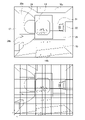
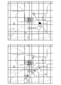
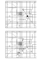
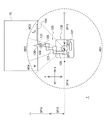
- An example of a schematic captured image of the inside of a machine tool and a grid area is shown.
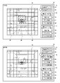
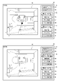
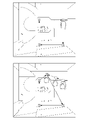
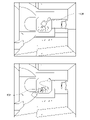
- An example of a display of a coolant injection path for automatic cleaning and an example of a display in the process of creating a coolant injection path for instructed cleaning are shown.
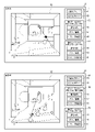
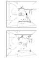
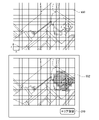
- An example of a display in the process of creating a coolant injection path for instructed cleaning is shown.
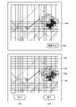
- An example of a display in the process of creating a coolant injection path for instructed cleaning is shown.
- An example of a display in the process of creating a coolant injection path for instructed cleaning is shown.
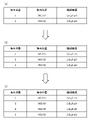
- An example of an injection route table is shown.
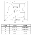
- An example of a display and an example of an injection route table in the process of creating a coolant injection route for instructed cleaning are shown.
- An example of a display and an example of an injection route table in the process of creating a coolant injection route for instructed cleaning are shown.
- 4 is a flow chart for explaining control processing for instructed cleaning.
- An example of a display in the process of creating a coolant injection path for instructed cleaning is shown.
- An example of a display in the process of creating a coolant injection path for instructed cleaning is shown.
- An example of a display in the process of creating a coolant injection path for instructed cleaning is shown.
- An example of a display and an example of an injection route table in the process of creating a coolant injection route for instructed cleaning are shown.
- An example of a display in the process of creating a coolant injection path for instructed cleaning is shown.
- An example of a display in the process of creating a coolant injection path for instructed cleaning is shown.
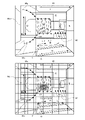
- An example of a cleaning path pattern in automatic cleaning is shown.
- the flowchart for explaining the control processing of automatic cleaning and the structure of a chip recognition part are shown.
- An example of a display of a captured image captured from another angle is shown.
- An example of a display regarding an angle switching operation is shown. It is an external view of a robot. It is a top view of a robot. It is a screen figure when designating a coolant injection path in manual washing mode. It is a screen figure which shows the injection state of the coolant in manual washing mode.
- FIG. 10 is a screen diagram when designating a selection area in the area cleaning mode; It is a screen figure which shows the coolant injection path
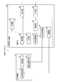
- FIG. 1 shows a functional block diagram of a machining system 1 according to this embodiment.
- a machine tool system 1 includes a machine tool 10 and an information processing device 30 .
- Each component of the machine tool 10 and the information processing device 30 that constitute the machine tool system 1 includes computing units such as a CPU (Central Processing Unit) and various co-processors (Co-processors), storage devices such as memories and storages, and connecting them. It is realized by hardware including wired or wireless communication lines and software stored in a storage device and supplying processing instructions to the computing unit.
- a computer program may consist of a device driver, an operating system, various application programs located in their higher layers, and a library that provides common functions to these programs.
- Each block illustrated in FIG. 1 indicates a functional unit block, not a hardware unit configuration.
- the machine tool 10 is a device that performs processing such as cutting and grinding on the workpiece that is to be processed and is carried into the machine tool 10 .
- the machine tool 10 includes a machine (machining center) in which a tool is attached to a main shaft to process a work, a machine (turning center) in which a plurality of tools are attached to a turret and the work is rotated and processed, and a material (for example, metal powder) is melted with a laser.
- machining center machine
- turning center machine which a plurality of tools are attached to a turret and the work is rotated and processed
- a material for example, metal powder
- the "information processing device” may be the operation panel itself of the machine tool, or may be a device other than the operation panel.
- the information processing device 30 generates a fluid injection path for injecting fluid into the machine tool 10 and moving scraps.
- the fluid injected into the machine tool 10 may be liquid such as lubricating liquid or coolant liquid, or gas such as air.
- the machining system of the present embodiment will be described with an example in which a liquid, which is a coolant, is used as the fluid, and chips generated by cutting or the like are used as the chips.
- the machine tool 10 includes a liquid injection section 11 , an imaging section 12 and a machine coordinate acquisition section 13 .
- the liquid injection part 11 injects the liquid so as to move the waste.
- the liquid ejector 11 includes, for example, a nozzle that can eject liquid, an actuator that drives the nozzle, and a pump that pumps up the liquid from the liquid reservoir that stores the liquid. By spraying liquid from the nozzle onto the chips, the chips can be moved to a chip conveyor or the like outside the machining area, and finally removed from the machining area.
- the liquid may be a coolant for cooling and lubricating the workpiece and the main shaft, which is a processing device, which generates heat during processing, or may be another liquid.
- coolant is an example of a "fluid injected into a machine tool.”
- the debris is displaced by injecting the coolant along the injection path.
- the liquid injection unit 11 can change the position of the nozzle, the injection direction of the coolant from the nozzle, the injection pressure of the coolant, and the like. It is preferable that the liquid ejecting portion 11 has a plurality of nozzles.
- the liquid injection area of one nozzle there is a spatial area that is hidden by the components of the machine tool 10 . This is because if chips enter the space area, the liquid flow from the nozzle cannot sufficiently act on the chips, making it difficult to move the chips.
- a gas injection section that injects gas to move the waste may be provided.
- the gas injection unit includes a nozzle that can inject gas, an actuator that drives the nozzle, and a pump that compresses gas (for example, air).
- the liquid ejector 11 is controlled in the same manner as the liquid ejector 11 .
- the image capturing unit 12 captures an image of a target area within the machine tool 10 for detecting scrap generated from machining the workpiece.
- the "target area within the machine tool” is a range where it is assumed that scraps generated from machining the workpiece are present.
- the imaging unit 12 is for imaging a wide range (including a horizontal plane and a side surface) in the processing chamber as described in relation to the upper image of FIG. 2, and is not for imaging individual scraps. .
- the image capturing unit 12 captures an image with a wider angle of view than when capturing an image of an individual piece of scrap. It is possible to ascertain the distribution of waste, that is, the dirtiness, from a wide range of captured images in the processing chamber.
- the imaging unit 12 is, for example, a camera equipped with an imaging device such as a CCD or CMOS, and is capable of imaging the inside of the machine tool 10 .
- the imaging unit 12 can output the captured image to the information processing device 30, which will be described later.
- the machine tool 10 may include a plurality of imaging units 12 within the machine tool 10 according to the performance and imaging range of the imaging units 12 .
- the machine tool 10 in this embodiment is provided with two imaging units 12 . Even in this case, by arranging another imaging unit so that an area that cannot be imaged by one imaging unit can be imaged, the entire machining area in the machine tool 10 can be captured from an image captured by the imaging unit. can be confirmed.
- the machine coordinate acquisition unit 13 can acquire machine coordinates representing the positions of the parts inside the machine tool 10 for moving parts such as the pallet 14 and the spindle 22, which will be described later in detail. can.
- the acquired machine coordinates can be transmitted to the display control unit 39 of the information processing device 30, which will be described later.
- position information transmitted from the NC controller to the machine tool 10 for machining can be used.
- Location information obtained using sensors can also be used.
- the information processing device 30 includes an arithmetic unit 31 that processes a captured image captured by the imaging unit 12 of the machine tool 10 and transmits a signal to the machine tool 10, and a display unit that displays the captured image captured by the imaging unit 12. 32 , a storage unit 33 for storing information such as images and positions processed by the calculation unit 31 as needed, and an input unit 34 for outputting an input signal to the calculation unit 31 .
- the information processing device 30 is, for example, a device such as a computer or tablet that has a function of receiving and displaying an image.
- the captured image captured by the imaging unit 12 is an example of the “image inside the machine tool”.
- the image may be a moving image, a still image, or a drawing simulating the structure of the machine tool.
- the display unit 32 is, for example, a computer display, and can display an image captured by the imaging unit 12 of the machine tool 10 and output to the information processing device 30 .
- an image processed by the calculation unit 31 with respect to the captured image may be displayed, such as by displaying a combination of grids created by the division unit 36, which will be described later.
- information such as the presence or absence of chips and the amount of chips can be displayed in the grid area formed by the grid.
- the display unit 32 may be a so-called touch panel, such as a display of a resistive film system or a capacitive system, which enables an operator to directly instruct based on an image by touching the displayed image for processing to be described later. .
- the input unit 34 is, for example, a mouse, which is a general input device for computers.
- the mechanism for detecting the position touched by the operator which is part of the display described above, corresponds to the input section 34 (and the detection section 38 described later).
- the input unit 34 outputs the instruction to the detection unit 38 as an input signal.
- the calculation unit 31 includes an acquisition unit 35 , a division unit 36 , a chip recognition unit 37 , a detection unit 38 , a display control unit 39 and a transmission unit 40 .
- the computing unit 31 and each of the processing units 35 to 40 included in the computing unit 31 includes a general-purpose processor such as a CPU or MPU that implements a predetermined function by executing a program.
- the computing unit 31 and the processing units 35 to 40 included in the computing unit 31 call and execute control programs stored in the storage unit 33, for example, thereby realizing various processes in the information processing device 30.
- the computing unit 31 and the processing units 35 to 40 included in the computing unit 31 are not limited to those that achieve predetermined functions through the cooperation of hardware and software, but hardware specifically designed to achieve predetermined functions.
- a wear circuit may be used. That is, the arithmetic unit 31 and the processing units 35 to 40 included in the arithmetic unit 31 can be realized by various processors such as a CPU, MPU, GPU, FPGA, D
- the acquisition unit 35 acquires an image captured by the imaging unit 12 and outputs it to the display unit 32 or the dividing unit 36.
- the dividing unit 36 can divide at least part of the captured image captured by the imaging unit 12 into a plurality of grid areas.
- the grid area is an area in which the captured image is divided by a predetermined geometric shape (grid).
- grid geometric shape
- the captured image of the inside of the machine tool 10 is divided into square grid areas.
- An image composed of such a plurality of grid areas can be called a grid image.
- the size and shape of the dividing grid may be configured to be changed as needed. By dividing into grid areas in this way, the operator can easily indicate the position.
- the grid image in the present specification is not limited to a new image generated by adding grid information to a captured image, and may be an image obtained by associating a captured image with a grid.
- a captured image and a grid stored as separate data are also referred to as grid images.
- the grid area is output to display section 32 and detection section 38 .
- the work system 1 may be configured without the dividing section 36 .
- the captured image acquired by the acquisition section 35 is output to the display section 32 and the detection section 38 .
- the lower left end of the image is the origin
- the horizontal direction is the X axis
- the right direction is the positive direction of the X coordinate
- the vertical direction is the Y axis
- the upward direction is the positive direction of the Y coordinate.
- the chip recognition unit 37 automatically recognizes chips based on the grid area created from the captured image in the dividing unit 36, and determines whether or not chips exist in the grid area. A judgment is made as to the amount of chips present. When it is determined that there are chips in the grid area, the chip recognition unit 37 recognizes a position on the captured image corresponding to the grid area in the grid image as a stacking position of the chips. When the chip stacking position is recognized, an automatic detection signal is output to the display control section 39 .
- the automatic detection signal includes at least information regarding the predetermined location where debris has been recognized in the captured image.
- the detection unit 38 Based on the image displayed on the display unit 32, the operator operates the input unit 34, and the detection unit 38 receives a signal including position information output from the input unit 34. Therefore, based on the captured image captured by the imaging unit 12, it is possible to detect the stacking state of chips at the position indicated by the input unit 34 by the operator. If there are a plurality of designated positions, the detector 38 detects a plurality of input signals according to the number. For example, when there are two pointing positions, a first input signal for the first pointing position and a second input signal for the second pointing position are detected. The detection unit 38 may detect the pointing position based on the grid area created by the division unit 36 .
- the display control unit 39 sets the coolant injection position based on the automatic detection signal in the automatic cleaning mode. Based on the automatic detection signal output from the chip recognition unit 37 or the detection unit 38, a predetermined position in the captured image is acquired, and a related area where chips are accumulated inside the machine tool 10 (the amount of chips is based on the reference area beyond).
- the display control unit 39 sets a predetermined coolant injection path, the details of which will be described later, according to the related area.
- the display control unit 39 causes the display unit 32 to display a predetermined coolant injection path. Based on the set coolant injection path, the transmitter 40 sends a control signal including information to the liquid injection unit 11 to inject the coolant at least to the relevant area. Therefore, since the liquid injection part 11 can be controlled based on the automatic detection signal, the liquid injection part 11 is controlled by recognizing or inputting the predetermined position, thereby injecting the coolant and moving the chips. be able to.
- the display control unit 39 forms a coolant injection path in the target area based on a plurality of indicated positions (for example, the first indicated position and the second indicated position) and generates a control signal.
- the control signal is a signal that controls to inject coolant based on the injection path.
- the transmission unit 40 outputs a coolant injection signal to the liquid injection unit 11 .
- the injection signal is a signal for injecting coolant to move the chip to the associated area associated with the indicated predetermined location of the chip.
- the nozzle of the liquid injection part 11 of the machine tool 10 injects the coolant to the relevant area by a predetermined cleaning method.
- the machine tool system 1 does not include the transmission section 40, and the signal is directly output from the display control section 39 to the liquid injection section 11. can also
- the storage unit 33 is a recording medium for recording various information.
- the storage unit 33 is realized by, for example, DRAM, SRAM, flash memory, MRAM, ReRAM, FeRAM, SSD (Solid State Device), hard disk, other storage devices, or an appropriate combination thereof.
- the storage unit 33 stores the captured image acquired by the acquiring unit 35, the grid area (grid image) created by the dividing unit 36, the information on the predetermined position where the chip recognition unit 37 recognizes that chips exist, and the chip. information on the amount of , information on the predetermined position detected by the detection unit 38, information on the relationship between the predetermined position and the related area, and the like can be stored. Further, each processing unit of the calculation unit 31 can read images and information stored in the storage unit 33 as necessary.
- each processing unit of the calculation unit 31 may read an image and information from the storage unit 33 at the time of image processing or signal detection. The received information may be stored in the storage unit 33 .
- the upper image in FIG. 2 is a captured image of the inside of the machine tool 10, and includes a pallet 14, a revolving door 17, a side surface 18a, a side surface 18b, an inclined plane 19, a plane surface 20, a chute 21, a spindle 22, a central portion 24, Sides 26a and 26b are shown.
- the rotation axis of the main shaft 22 shown in the upper image of FIG. 2 is the front-rear direction inside the machine tool 10
- the root side of the main shaft 22 is the front side
- the tip side is the back side.
- a horizontal direction orthogonal to the rotation axis is defined as a left-right direction
- a vertical direction orthogonal to the rotation axis is defined as an up-down direction.
- the pallet 14 is a table on which the work is placed and fixed.
- Machine tool 10 may be provided with a plurality of pallets 14 . As a result, when changing the work to be processed, the work can be changed by changing the pallet 14, and the efficiency of time can be improved.
- the revolving door 17 is a door that can rotate around a central axis. When replacing the pallet 14, the revolving door 17 is rotated.
- the side 18b is a wall of the machine tool 10 that can be opened and closed.
- the side 18b separates the inside of the machine tool 10 from the outside, and an operator can enter the inside of the machine tool 10 by opening the side 18b.
- a side surface a located opposite to the side surface 18b separates the inside of the machine tool 10 from the tool storage section.
- the tool storage section stores a plurality of tools, and during machining, the side surface 18a is opened as necessary to replace the tool attached to the spindle 22 with another tool stored in the tool storage section. be able to.
- the shooter 21 is a place where chips flow through cleaning.
- the slope 19 slopes downward toward the shooter 21 so that chips can easily flow to the shooter 21 .
- a tool is attached to the tip of the spindle 22, and the workpiece can be machined by rotating it around the rotation axis.
- the main shaft 22 has a cylindrical profile.
- the upper screen in FIG. 3 shows an example of the display section 32 of the work system 1.
- the display unit 32 includes a screen unit 50 that displays captured images and grid images, a mode selection area 51 , a first image selection area 52 and a second image selection area 53 .
- Each selection area 51 to 53 is detected by the detection unit 38 when the operator instructs (for example, when the display unit 32 is a touch panel, by touching the display unit 32), and the cleaning method and the screen unit 50 display. It has an area (selection section) for selecting an image to be displayed.
- the mode selection area 51 has an automatic cleaning mode selection portion 54 and an instruction cleaning mode selection portion 55. By selecting the automatic cleaning mode selection portion 54 or the instruction cleaning mode selection portion 55, the automatic cleaning mode or the instruction cleaning mode is selected. can be changed.
- the first image selection area 52 shows an image displaying the ejection direction of the first coolant by one of the liquid ejecting units 11 as seen from one of the two imaging units 12 in this embodiment.
- This imaging unit 12 images the inside of the processing chamber from above.
- the first image selection area 52 has a captured image selection section 56 , a grid image selection section 57 , and a coolant injection path selection section 58 .
- the image captured by the imaging section 12 is displayed on the screen section 50 .
- the grid image selection section 57 is selected, the grid image created by the division section 36 is displayed on the screen section 50 .
- the second image selection area 53 displays on the screen an image viewed from an imaging unit 12 different from the image of the first image selection area 52 and viewed in the direction in which the second coolant is ejected by another liquid ejecting unit 11 .
- This is a selection area for The second image selection area 53 has a captured image selection section 59, a grid image selection section 60, and a coolant injection path selection section 61.
- the selection sections 59 to 61 correspond to the selection sections 56 to 58 of the first image selection area 52. behaves similarly to
- a separate imaging unit and a separate liquid ejecting unit are described, but the present invention is not limited to this.
- the image pickup unit may be configured to move and pick up images from different angles.
- the liquid ejecting part may be configured such that the liquid ejecting part itself moves such as translation and rotation, is positioned in the ejection direction of the second coolant, and ejects the coolant.
- the automatically set coolant injection path is displayed on the screen portion 50 as shown in the upper screen of FIG.
- the grid area in the grid image displayed on the screen unit 50 is an example of "a plurality of partitioned grids". That is, the display control unit 39 performs control so that the captured image data is divided into a plurality of grids including the "first grid” and the "second grid” and displayed.
- Grid areas 67 where no pattern is shown correspond to "no swarf (class 0)”.
- Grid areas 68 showing a thin pattern correspond to "Low Chipping (Class 1)”.
- a grid area 69 with a dark pattern corresponds to "scratchy (class 2)”.
- Grid area 68 with a thin pattern is an example of a "first grid.”
- a grid area 69 with a dark pattern is an example of a "second grid.”
- the image shown in the grid area 68 where the light pattern is shown is an example of "image data corresponding to the first grid”.
- "Small amount of chips (class 1)” is an example of "the amount of chips detected from the image data corresponding to the first grid”.
- the image shown in the grid area 69 where the dark pattern is shown is an example of "image data corresponding to the second grid”.
- "There are many chips (class 2)” is an example of "the amount of chips detected from the image data corresponding to the second grid”.
- the operator can confirm that "the amount of dust detected from the image data corresponding to the first grid” and "the amount of dust detected from the image data corresponding to the second grid" are different from each other by the density of the pattern. is visually identifiable.
- a thin pattern is an example of a mode of displaying so that it can be seen that the amount of debris in the "first grid” is small.
- a dark pattern is an example of a mode of displaying so that it can be seen that the amount of dust in the "second grid” is large.
- the display control unit 39 determines that the amount of dust detected from the image data corresponding to the "first grid” differs from the amount of dust detected from the image data corresponding to the "second grid”. In this case, control is performed so that the "first grid” and the "second grid” are superimposed on the image data so that it can be seen that the amounts of dust are different.
- the background color may be used instead of the pattern density. For example, in the case of "few chips (class 1)", a yellow background color is given, and in the case of "a lot of chips (class 2)", an orange background color is given.
- the operator can specify a predetermined position to be cleaned (for example, by touching the screen section 50) with respect to the grid image or the captured image displayed on the screen section 50.
- the screen at the bottom of FIG. 3 is a display example when the operator instructs the coolant injection position on the grid image created by the dividing unit 36 from the captured image.
- the lower screen of FIG. 3 is displayed when the coolant injection path selection section 58 is selected following the grid image selection section 57 . If the grid image is displayed as a base, the operator can easily recognize areas with a large amount of chips. However, the operator may designate the coolant injection position for the captured image in which the grid is not displayed. If the captured image is displayed as a base, the operator can determine the cleaning range while looking at the chips.
- FIG. 4 shows an example of displaying a captured image.
- the display unit 32 includes the screen unit 50 and the selection units 54 to 61.
- the display unit 32 includes only the screen unit 50, and the other selection units are mechanical It may be configured as a switch.
- the user interface and processing in creating the coolant injection path will be described with reference to FIG.
- the first touch position is an example of "the first position on the image within the machine tool".
- the "first position on the image within the machine tool” can be arbitrarily designated by the operator by user operation such as tapping on the screen or clicking the mouse.
- the detection unit 38 detects a "first input signal” for the "first position” through input on the input unit 34 (touch panel or mouse).
- the "first input signal” includes coordinate values (two-dimensional position coordinates) of the "first position".
- the display control unit 39 causes the display unit 32 to display a circle mark of “1” at the first touch position. Along with this, the display control unit 39 provides the first record of the injection route table shown in FIG. 7(A).
- the injection route table is stored in the storage section 33 .
- the designated position (X1, Y1) indicates the two-dimensional position coordinates of the first touch position on the screen section 50 .
- Machine coordinates (x1, y1, z1) indicate three-dimensional position coordinates on a part within machine tool 10 corresponding to indicated position (X1, Y1). It is assumed that the correspondence relationship between the indicated position and the machine coordinates is obtained in advance and stored in the storage unit 33 .
- the display control unit 39 can convert the indicated position into machine coordinates based on this correspondence relationship.
- the machine coordinates may be three-dimensional position coordinates in space within the machine tool instead of three-dimensional position coordinates on the part within the machine tool.
- the second touch location is an example of a "second location on the image within the machine tool.”
- the "second position on the image inside the machine tool” can also be arbitrarily specified by the operator by user operation such as tapping on the screen or clicking the mouse.
- the detection unit 38 detects a "second input signal” for the "second position” through an input on the input unit 34 (touch panel or mouse).
- the "second input signal” includes coordinate values (two-dimensional position coordinates) of the "second position”.
- the "second position” is, for example, the position specified next to the "first position” by the operator.
- the display control unit 39 causes the display unit 32 to display a circle mark "2" at the second touch position. Along with this, the display control unit 39 provides the second record of the injection route table shown in FIG. 7(A).
- the indicated position (X2, Y2) indicates the two-dimensional position coordinates of the second touch position on the screen section 50 .
- Machine coordinates (x2, y2, z2) indicate three-dimensional position coordinates on a part within machine tool 10 corresponding to indicated position (X2, Y2).
- the display control unit 39 displays an arrow line from the "1" circle mark to the "2" circle mark on the screen.
- Arrow lines indicate coolant injection paths, ie fluid injection paths.
- the display control unit 39 controls the display unit 32 to display the predetermined position and the fluid ejection path superimposed on the image data in the machine tool 10 .
- first position “first position”, “second position”, and “fluid ejection path connecting the first position and the second position” are displayed.
- a “fluid ejection path connecting the first position and the second position” is indicated by an arrow line (segment) connecting the first position and the second position.
- the information processing device 30 generates the ejection path of the liquid "based on the first position and the second position in the image captured by the imaging unit 12".
- the image data in the machine tool 10 that the display control unit 39 uses as a base is imaged by the imaging unit 12 .
- the operator of this embodiment selects an arrow line from the circle mark "1" to the circle mark "2". Perform a touch operation by touching .
- a touch operation on an arrow line is an example of a user operation for selecting a fluid ejection path.
- the display control unit 39 causes the display unit 32 to display a black circle mark in the middle of the arrow line from the circle mark "1" to the circle mark "2".
- a black circle mark indicates a passing point.
- the display control unit 39 causes the display unit 32 to display the "passing point" between the "first position” and the “second position” when the "injection route", which is the arrow line, is selected. . It is assumed that the operator can perform user operations such as tapping on the screen or clicking a mouse to select the injection route.
- the detection unit 38 detects "selection of an ejection path" by a user's operation through an input on the input unit 34 (a touch panel or a mouse). In this example, an arrow line is selected as the "injection path”.
- a "1" circle mark is an example of a "first position.”
- the "2" circle mark is an example of the "second position”.
- a black circle mark is an example of a displayed "passing point”.
- the operator selects a black circle mark (for example, a touch operation of touching the black circle mark on the screen) and performs a slide operation.
- a touch operation and a slide operation on the black circle mark correspond to a user operation of selecting and moving the progress point.
- the display control unit 39 causes the display unit 32 to display the black circle mark by moving the image data in the machine tool 10 according to the slide operation. Then, the operator cancels the selection (for example, performs a release operation to release the touch from the black circle mark on the screen). As a result, the display control unit 39 causes the display unit 32 to display the circle mark "3" instead of the black circle mark. At this time, the display control unit 39 inserts the second record of the injection route table shown in FIG.
- the indicated position (X3, Y3) indicates the two-dimensional position coordinates of the release position on the screen section 50.
- FIG. Machine coordinates (x3, y3, z3) indicate three-dimensional position coordinates on the part within the machine tool 10 corresponding to the indicated position (X3, Y3).
- the display control unit 39 causes the display unit 32 to display an arrow line from the circle mark "1" to the circle mark "3” and an arrow line from the circle mark "3" to the circle mark "2". That is, the coolant ejection path (fluid ejection path) moves along with the touch operation and the slide operation.
- the display control unit 39 selects the injection route, displays the passing point, and when the "passing point” is moved, moves the "passing point” on the image data and causes the display unit 32 to display it. control. It is assumed that the operator can perform a user operation such as a slide operation on the screen or a mouse drag operation to “move the passing point”.
- a circle mark of "3" is an example of a transition point after movement.
- the display control unit 39 sequentially displays the first position (“1” circle mark), the transition point (“3” circle mark) at the post-movement position, and the second position (“2” circle mark). Control is performed to display the fluid ejection path connecting the three positions on the display unit 32 .
- the operator touches the arrow line from the "3" circle mark to the "2" circle mark.
- the display control unit 39 causes the display unit 32 to display a black circle mark indicating a passing point in the middle of the arrow line from the circle mark "2" of "3" to the circle mark.
- the operator similarly performs a slide operation and a release operation.
- the display control unit 39 causes the display unit 32 to display a circle mark "4" instead of the black circle mark.
- the display control unit 39 inserts the third record of the injection route table shown in FIG. 7(C).
- the display control unit 39 displays an arrow line from the "1" circle mark to the "3” circle mark, an arrow line from the "3” circle mark to the "4" circle mark, and a "4" circle mark. to the circle mark “2” is displayed on the display unit 32 .
- the ejection paths for ejecting the fluid in the order of 1 ⁇ 3 ⁇ 4 ⁇ 2 are created. It is also possible to inject the fluid in the opposite direction such as 2 ⁇ 4 ⁇ 3 ⁇ 1.
- double-clicking the circle mark of "1" may reconfigure the injection route so that the 1 is the last one. It may also be possible to select an injection path that is an arrow between "3" and "4" and invert the arrow to create an injection path. For example, if the arrow between "3" and "4" is reversed, the following order is taken: 1 ⁇ 3 ⁇ (positional movement without fluid injection) ⁇ 4 ⁇ 3 ⁇ (positional movement without fluid injection) ⁇ 4 ⁇ 2. It becomes a route through which the fluid is ejected in order.
- the upper screen in FIG. 8 shows only the part of the captured image, which is a part displayed on the display unit 32.
- the operator repeats the same user operation to place a circle mark "5" between the circle mark "4" and the circle mark "2".
- a circle mark of "6” is provided between the circle mark of "2” and the circle mark of "2"
- a circle mark of "7” is provided between the circle marks of "5" and “6”
- a circle mark of "1” is provided.
- a circle mark of "8” is provided between the circle mark of "3" and the circle mark of "3”.
- the operator performs a touch operation, a slide operation, and a release operation on the "1" circle mark on the bottom screen of FIG.
- the display control unit 39 rewrites the indicated position in the first record of the injection route table (FIG. 7C) from (X1, Y1) to (X101, Y101), as shown in the lower part of FIG. (X101, Y101) is the release position of the "1" circle mark. Further, the display control unit 39 rewrites the machine coordinates from (x1, y1, z1) to (x101, y101, z101). Then, the display control unit 39 redisplays the arrow line from the circle mark "1" to the circle mark "3".
- the operator performs touch operation, slide operation, and release operation on the circle mark "3" on the lower screen of FIG.
- Display control unit 39 As shown at the bottom of FIG. 9, the indicated position in the second record of the injection route table (FIG. 7(C)) is rewritten from (X3, Y3) to (X103, Y103). (X103, Y103) is the release position of the circle mark "3".
- the display control unit 39 rewrites the machine coordinates from (x3, y3, z3) to (x103, y103, z103). Then, the display control unit 39 redisplays the arrow line from the circle mark "1" to the circle mark "3” and the arrow line from the circle mark "3" to the circle mark "4".
- FIG. 10 is a flow chart showing an operation example of directed cleaning of the machining system 1 in this embodiment.
- the imaging unit 12 of the machine tool 10 captures an image
- the acquisition unit 35 of the information processing device 30 acquires the captured image (S30).
- the dividing unit 36 creates a grid area for the captured image acquired in step S30 to create a grid image (S31).
- the display unit 32 displays the grid image or captured image created in step S31 (S32).
- the detection unit 38 detects it as an input signal to each position (S33). When the detection unit 38 detects the input signal, the detection unit 38 passes the input signal to the display control unit 39 (S34).
- the display control unit 39 forms an injection route in consideration of the designated order of the coolant in the target area based on the input signal, and controls to inject the coolant based on the injection route.
- a control signal (including ordered machine coordinates) is generated (S35).
- the display unit 32 displays the formed ejection path by superimposing it on the captured image or the grid image (S36).
- the operator checks the injection route, and if there is any correction, the process returns to step S33 (S37). If there is no correction, the transmission unit 40 transmits the generated control signal to the machine tool 10 (S38), and the machine tool 10 drives the nozzle to inject the coolant according to the direction of the arrow line of the injection path, thereby injecting the coolant. (S39) and ends.
- FIG. 5 shows an example in which the captured image is displayed on the screen unit 50 as a base, but as shown in FIG. 11, the grid image may be displayed as a base.
- the mode selection area 51 shown in FIG. 5 is the same in FIG. 11 as in FIG. 5, although the automatic cleaning mode selection section 54 and the instruction cleaning mode selection section 55 are omitted.
- the operation method and control processing are the same as in the case of FIG. 5 except that the grid image is displayed. If the grid image is displayed as a base, the operator can easily recognize areas with a large amount of chips. Further, as shown in FIG. 12, based on the data from before the machining until now, the locations where chips are likely to accumulate may be indicated, and the coolant injection paths may be created based on the locations. In this case, the coolant injection path can be created on the screen without chips on the image.
- a square coolant injection path may be generated based on the two designated positions.
- sensing unit 38 outputs a first input signal for a first position on the image within machine tool 10, a second input signal for a second position on the image within machine tool 10, and a second input signal for multiple injections.
- the display control unit 39 detects (i) a first position, (ii) a second position, and a straight line connecting the first position and the second position as a diagonal line.
- the third position and (iv) the fourth position which are corners different from the first position and the second position among the four corners of the quadrangle, are superimposed on the image data in which the target area is captured. Control the display.
- a reciprocating mode selection section 80, an injection direction+selection section 81, and an injection direction-selection section 82 are displayed.
- the mode selection area 51, the first image selection area 52, and the second image selection area 53 are the same as described above, and therefore are omitted.
- the display control unit 39 displays a circle mark of "1" at the first touch position.
- the display control unit 39 provides the first record of the injection route table shown in FIG. 14(A).
- the injection route table is stored in the storage section 33 .
- the designated position (X1, Y1) indicates the two-dimensional position coordinates of the first touch position on the screen section 50 .
- Machine coordinates (x1, y1, z1) indicate three-dimensional position coordinates on a part within machine tool 10 corresponding to indicated position (X1, Y1). It is assumed that the correspondence relationship between the indicated position and the machine coordinates is obtained in advance and stored in the storage unit 32 .
- the display control unit 39 can convert the indicated position into machine coordinates based on this correspondence relationship.
- the second touch location is an example of a "second location on the image within the machine tool.”
- the "second position on the image within the machine tool” can be arbitrarily designated by the operator by user operation such as tapping on the screen or clicking the mouse.
- the detection unit 38 detects a "second input signal” for the "second position” through an input on the input unit 34 (touch panel or mouse).
- the "second input signal” includes coordinate values (two-dimensional position coordinates) of the "second position".
- the "second position” is, for example, the position specified next to the "first position” by the operator.
- the display control unit 39 When the second touch operation on the position indicated by the circle mark “2" is detected, the display control unit 39 causes the circle mark “2" to be displayed at the second touch position, and the circle mark "1". An arrow line pointing from the mark to the circle mark "2" is displayed on the screen. Along with this, the display control unit 39 provides the second record of the injection route table shown in FIG. 14(A).
- the indicated position (X2, Y2) indicates the two-dimensional position coordinates of the second touch position on the screen section 50 .
- Machine coordinates (x2, y2, z2) indicate three-dimensional position coordinates on a part within machine tool 10 corresponding to indicated position (X2, Y2).
- the detection unit 38 detects the "third input signal regarding multiple injections" through input on the input unit 34 (touch panel or mouse). Selection of the reciprocating mode selection unit 80 is performed by the operator by user operation such as tapping on the screen or clicking a mouse. “Multiple injections” means that the injection is performed two or more times while being linearly moved. As shown in the upper screen of FIG. 14, in this example, four injections are performed while moving linearly.
- the display control unit 39 displays the circle mark “1” and the circle mark “2” on the display unit 32 as shown in the lower screen of FIG.
- a circle mark of "3" and a circle mark of "4" are displayed at other diagonal positions of the quadrangle to be a corner.
- the display control unit 39 controls the “first position”, the “first position”, the Control is performed to display “second position”, “third position” and “fourth position”.
- Circle marks "1" to "4" are examples of "first position” to "fourth position", respectively.
- the 'third position' and 'fourth position' are defined as 'a corner different from the first position and the second position among the four corners of a quadrangle whose diagonal is a straight line connecting the first position and the second position'. be.
- a quadrangle whose sides are the line segments connecting the circle mark 4 and the number 1 corresponds to a quadrangle whose diagonal is a straight line connecting the first position and the second position.
- "a quadrangle whose diagonal is a straight line connecting the first position and the second position” is a square, but it may be a quadrangle other than a square (such as a rectangle or a rhombus).
- the "first position”, “second position”, “third position” and “fourth position” are displayed "superimposed on the image data obtained by imaging the target area".
- the display control unit 39 causes the display unit 32 to display the clockwise injection route, as shown in the upper screen of FIG. That is, the display control unit 39 controls the arrow line from the "1" circle mark to the "3” circle mark, the arrow line from the "3” circle mark to the “2” circle mark, and the "2" circle mark. to the circle mark "4" and an arrow line from the circle mark "4" to the circle mark "1" are displayed. Along this arrow line, four injections are shown. The display control unit 39 inserts the second record and the fourth record of the injection route table shown in FIG. 14(B).
- the designated position (X3, Y3) indicates the two-dimensional position coordinates of the position of the circle mark “3” on the screen section 50 .
- Machine coordinates (x3, y3, z3) indicate three-dimensional position coordinates on the part within the machine tool 10 corresponding to the indicated position (X3, Y3).
- the designated position (X4, Y4) indicates the two-dimensional position coordinates of the position of the circle mark “4” on the screen section 50 .
- Machine coordinates (x4, y4, z4) indicate three-dimensional position coordinates on the part within the machine tool 10 corresponding to the indicated position (X4, Y4).
- the display control section 39 causes the display section 32 to display the counterclockwise injection route. That is, the display control unit 39 controls the arrow line from the "1" circle mark to the "4" circle mark, the arrow line from the "4" circle mark to the "2" circle mark, and the "2" circle mark. to the circle mark “3” and an arrow line from the circle mark "3" to the circle mark "1” are displayed. Then, the display control unit 39 generates an injection route table in which the records are arranged in the order of instruction order "1", "4", "2", and "3". The display control unit 39 controls the injection path (clockwise or the counterclockwise injection route) may be displayed. Even if the reciprocating mode selection unit 80 is not selected, the display control unit 39 performs the above-described The display may be switched to an injection route forming a square (clockwise injection route or counterclockwise injection route).
- the operator performs a touch operation and a slide operation on the "4" circle mark on the upper screen of FIG.
- the display control unit 39 causes the display unit 32 to move the circle mark "4" according to the slide operation.
- a touch operation on the circle mark "4" corresponds to "selection of the fourth position".
- the selected circle mark "4" is moved by a slide operation as a selection point.
- the display control unit 39 When the operator releases the "4" circle mark, the display control unit 39 causes the display unit 32 to display the "4" circle mark as shown in the lower screen of FIG.
- the display control unit 39 rewrites the indicated position in the fourth record of the injection route table from (X4, Y4) to (X104, Y104) as shown in FIG. 14(C).
- (X104, Y104) is the release position of the round mark "4" shown in the lower screen of FIG.
- the display control unit 39 rewrites the machine coordinates from (x4, y4, z4) to (x104, y104, z104).
- the display control unit 39 redisplays the arrow line from the circle mark "2" to the circle mark "4" and the arrow line from the circle mark "4" to the circle mark "1". That is, the display control unit 39 displays the circle mark of "1" (first position), the circle mark of "3” (third position), the circle mark of "2” (second position), and the moved circle mark of "4". Control is performed to display a rectangular injection route configured in the order of circle marks (selection points).
- the operator touches the arrow line from the "4" circle mark to the "1" circle mark.
- a touch operation on an arrow line is an example of a user operation for selecting a coolant ejection path (fluid ejection path).
- the display control unit 39 causes the display unit 32 to display a black circle mark in the middle of the arrow line from the circle mark "4" to the circle mark "1".
- a black circle mark indicates a passing point. In this manner, the display control unit 39 performs control to display the passing point between the circle mark of "1" (first position) and the circle mark of "4" (fourth position).
- the operator slides the touched black dot.
- a touch operation and a slide operation on the black circle mark correspond to a user operation of selecting and moving the progress point.
- the display control unit 39 moves and displays the black circle mark, which is the transition point between the circle mark "1" (first position) and the circle mark "4" (fourth position), according to the slide operation. 32 is caused to display.
- the display control unit 39 switches the black circle mark to the circle mark “5” and causes the display unit 32 to display it.
- the display control unit 39 adds the fifth record to the injection route table shown in FIG. 14(D).
- the designated position (X5, Y5) indicates the two-dimensional position coordinates of the release position on the screen section 50.
- FIG. Machine coordinates (x5, y5, z5) indicate three-dimensional position coordinates on the part within the machine tool 10 corresponding to the indicated position (X5, Y5).
- the display control unit 39 causes the display unit 32 to display an arrow line from the circle mark "4" to the circle mark "5" and an arrow line from the circle mark "5" to the circle mark "1". In this way, when the black circle mark (passing point) is moved, the display control unit 39 controls the circle mark "4" (fourth position), the circle mark "5" switched from the moved black circle mark (after the movement). , and the circular mark of "1" (first position) in order to display the fluid ejection path connecting the three positions.
- the coolant injection path for automatic cleaning will be described.
- a case in which coolant is injected based on an automatic detection signal from the chip recognition unit 37 is referred to as automatic cleaning.
- the coolant injection route it is possible to select a coolant injection route corresponding to the relevant region from among a plurality of coolant injection routes stored in advance in the storage unit 33, or to select an optimum coolant injection route based on a predetermined algorithm. can also be formed. Furthermore, it is also possible to form an optimum coolant injection path using a predetermined learning model.
- the upper diagram in FIG. 17 shows an example of the cleaning path pattern superimposed on the captured image.
- the bottom diagram of FIG. 17 shows an example of a cleaning path pattern superimposed on the grid image. Automatic cleaning may be performed while the captured image is displayed, or automatic cleaning may be performed while the grid image is displayed.
- areas A to G are set.
- a cleaning path pattern is stored according to the area, and automatic cleaning is performed.
- Area A includes the pallet 14.
- area A is associated with a zigzag coolant injection path for the pallet 14 indicated by an arrow 64 .
- the coolant injection path indicated by arrow 64 in FIG. 17 is selected and set as shown in the upper screen of FIG.
- the upper screen of FIG. 3 shows a pattern indicating the division of the grid area and the amount of chips. Grid areas where no pattern is shown correspond to "no swarf (class 0)" described below. Grid areas with a thin pattern also correspond to "low chipping (class 1)". Grid areas with a dark pattern also correspond to "scratchy (class 2)".
- Area B includes slope 19 and plane 20 .
- the region B is associated with the coolant injection path indicated by an arrow 61 that reciprocates straight from above with respect to the slope 19 of the region B2.
- a washing coolant injection path directed toward shooter 21 indicated by arrow 62 is associated with plane 20 of area B1.
- the region D includes the side portion 26a, the side portion 26b, and the central portion 24.
- a plurality of straight cleaning coolant injection paths in one direction away from the revolving door 17 indicated by arrows 65a and 65b are associated with the side portions 26a and 26b.
- the area D is associated with a plurality of straight cleaning coolant injection paths reciprocating in a direction parallel to the revolving door 17 indicated by an arrow 65c.
- the area F includes the side surface 18a.
- the area F is associated with the straight coolant injection path above the side surface 18 a indicated by the arrow 63 .
- the display control unit 39 determines that the amount of chips in the area F exceeds the reference, the coolant injection path indicated by the arrow 63 is selected and set.
- Region G includes side surface 18b.
- the region G is associated with the straight coolant injection path above the side surface 18 b indicated by the arrow 66 .
- the display control unit 39 determines that the amount of chips in the area G exceeds the reference, the coolant injection path indicated by the arrow 66 is selected and set.
- Areas C and E are also associated with coolant injection paths, but they are omitted.
- a workpiece is loaded into the machine tool 10 and machining is started (S10). Chips are generated by the processing.
- the imaging unit 12 of the machine tool 10 captures an image
- the acquisition unit 35 of the information processing device 30 acquires the captured image (S11).
- the dividing unit 36 divides the captured image captured in step S11 into a plurality of grid areas to create grid images (S12).
- the cutting waste recognition unit 37 determines the presence or amount of cutting waste for each grid area of the grid image created in step S12 (S13).
- the process returns to step S11 again to acquire a captured image. If there are no chips and the machining is completed, the operation of the machining system 1 is terminated (S14). If there are chips, the chip recognition unit 37 outputs to the display control unit 39 an automatic detection signal including predetermined position information on the captured image corresponding to the position of the grid area in the grid image and information on the amount of chips ( S15).
- the display control unit 39 identifies the related area (area where the amount of chips exceeds the reference) from the automatic detection signal, and causes the display unit 32 to display the coolant injection path in the related area.
- the transmission unit 40 outputs a control signal for the coolant injection path in the related region to the liquid injection unit 11 (S16).
- the control signal includes information on the cleaning sequence for injecting coolant to each related area when there are a plurality of related areas.
- the transmitter 40 transmits the injection signal to the machine tool 10 (S17).
- the machine tool 10 controls the liquid injection part 11 based on the control signal to inject the coolant to the relevant areas according to the washing order (S18).
- the process returns to step S11, and the above steps are repeated until the machining of the workpiece is completed.
- the above is the washing process by automatic washing.
- Chip recognition A method for automatically recognizing chips using captured images will be described.
- the block diagram at the bottom of FIG. 18 (“machine learning of chip detection by the chip recognition unit 37”) is a schematic diagram of the configuration of the chip recognition unit 37 that automatically recognizes chips.
- the chip recognition section 37 includes a model learning section 41 , a calculation section 43 and a determination section 44 .
- the storage unit 33 also includes a model storage unit 42 .
- the model learning unit 41 creates a learning model.
- the learning model calculates and outputs the probability of which of the predetermined items the chips in the grid region correspond to. It is a model that can
- a learning model can be created by, for example, inputting pairs of input data and output data as teacher data into a CNN (convolutional neural network) in advance for learning.
- a general CNN is a learning method in which image features are extracted by a convolution layer and a pooling layer, and the features are input to a neural network for processing, and is often used for image feature extraction.
- a learning model may be created using a learning method other than CNN.
- the input data can be the grid area
- the output data can be information about the presence and amount of chips in the grid area.
- the model storage unit 42 stores a learning model for automatically determining the presence or absence of chips.
- the learning model is read into the calculator 43 as needed.
- the chip recognition unit 37 includes the model learning unit 41
- the storage unit 33 includes the model storage unit 42.
- the learning model is created by a device other than the information processing device 30, and the storage unit 33 A method of storing the learning model in the storage and reading the learning model as necessary may be used.
- the calculation unit 43 calculates the probability that chips in the grid area correspond to predetermined items. Specifically, the calculation unit 43 uses the learning model learned by the model learning unit 41 to determine whether the grid area input as the input data is “many chips (class 2)” and “small chips (class 1)”. , "no chips (class 0)". In addition, the items may be further subdivided for calculation, or the probability of chips existing may be calculated simply.
- the determination unit 44 determines to which of classes 0 to 2 the chips belong to the grid region based on the probability calculated by the calculation unit 43 regarding the input grid region.
- the determination unit 44 can set how to determine based on the probability calculated by the calculation unit 43 regarding chips present in the grid area. For example, it may be determined to correspond to the highest item among the probabilities of classes 0 to 2 calculated by the calculation unit 43 . Also, as in the case where "class 2" is 25%, “class 1" is 35%, and "class 0" is 40%, the probability of "there are chips (class 2 + class 1)" is "chips When the probability is higher than the probability of "not present (class 0)", it may be determined to fall under "class 1" (or "class 2").
- the determination unit 44 determines that there is debris in the grid area (that is, determines that it is class 2 or class 1), the determination unit 44 automatically has at least position information on the captured image corresponding to the position of the grid area in the grid image.
- a detection signal is output to the display control unit 39 as described above.
- the auto-sensing signal may contain information regarding the amount of chips.
- the machine tool system 1 can automatically recognize the presence or absence of chips based on the captured image captured by the imaging unit 12 provided in the machine tool 10 .
- the machine tool system 1 can automatically recognize chips based on the captured image captured by the imaging unit 12 during or after machining of the workpiece, and perform automatic cleaning by injecting coolant. can.
- the automatic cleaning may be performed periodically, or may be performed by giving some instructions such as an instruction by an operator.
- Automatic cleaning may also recognize chips in multiple relevant areas.
- priority may be set in advance for the related areas, and the cleaning order may be set based on the priority and the accumulation state of chips (for example, the amount of chips) by the chip recognition unit.
- the priority is given to the pallet 14, which is considered to have the greatest effect on machining, with the highest priority, and the flat surface 20 and slope 19, on which chips tend to accumulate, and the revolving door 17, which moves out of the machine tool 10, are given the second highest priority.
- Priority may be given, and others may be given third priority.
- the spindle may be cleaned only when the tool is replaced.
- captured images captured from different angles may be displayed, and the coolant injection path may be created on the captured images. It is a captured image captured from a different angle (diagonally above) by an imaging unit installed at a position different from the imaging unit that captured the above-described captured image.
- the coolant injection path can be created by the same operation and processing as described above.
- the upper screen in FIG. 19 shows the same state as the lower screen in FIG.
- the lower screen of FIG. 19 shows the same state as the upper screen of FIG.
- the selected point can be moved outside the captured image, as indicated by the round mark "3" (third position) shown in the lower screen of FIG.
- the display control unit 39 also obtains the indicated position and the machine coordinates for the area outside the captured image, and sets them in the ejection path table.
- the angle of the captured image to be displayed may be switched. For example, as shown in FIG. 20, an imaging angle 1 selection section 91 and an imaging angle 2 selection section (upper surface) 92 are displayed. As shown in the upper screen of FIG. 20, when the operator selects the imaging angle 1 selection section 91, the display control section 39 displays the captured image captured from the first imaging angle (for example, obliquely upward). As shown in the lower screen of FIG. 20, when the operator selects the imaging angle 2 selection section (upper surface) 92, the display control section 39 displays the captured image captured from the second imaging angle (for example, directly above). display.
- the liquid injection unit 11 and the imaging unit 12 may be provided in a robot other than the machine tool 10 .
- the robot may perform imaging and liquid ejection.
- a robot having a gas injection unit and an imaging unit 12 may be used.
- the robot may perform imaging and gas injection.
- the injected gas is, for example, compressed air. Debris can also be moved by gas.
- a gas injection part may be used.
- FIG. 21 is an external view of the robot.
- FIG. 22 is a top view of the robot.
- a robot arm 125 of a serial link mechanism is provided on an upper surface 136 of a transfer device (AGV (Automatic Guided Vehicle)) 135 .
- Robotic arm 125 includes first arm 126 , second arm 127 and third arm 128 .
- a camera 131 and an air blow jet nozzle 130 are attached to the tip of the third arm 128 .
- the robot controller 137 can move the robot arm 125 to hold the camera 131 and spray nozzle 130 in any orientation and position. Further, the robot control device 137 causes the camera 131 to take an image, and ejects gas from the ejection nozzle 130 to remove chips.
- the robot may have the imaging unit, the machine tool may have the fluid ejection unit, and the personal computer other than the robot and the machine tool may have the display control unit. Which device includes each unit such as the display control unit can be selected as appropriate.
- FIG. 21 An example using the robot of FIG. 21 will be described.
- the transfer device on which the robot is mounted moves to the front of the machine tool and stops.
- a camera mounted on the robot captures images of the structure and marks inside the machine tool, and corrects the position of the robot. Since the robot holds a workpiece to be machined by the machine tool, it moves the workpiece so as to be placed inside the machine tool.
- the camera which is the imaging unit, acquires an image again to detect the installation position of the work and the state of the installation position.
- the robot injects gas from the injection nozzle to remove dust and the like from the installation position and its vicinity, and installs the work at the installation position after the gas is injected from the injection nozzle. Since the robot has an injection nozzle, the injection path can be created on the operation panel of the machine tool, or a computer such as a tablet separate from the machine tool or robot can be used to determine how to inject the gas. good too.
- the display unit 32 and the input unit 34 may be provided separately from the information processing device 30 .
- the display unit 32 and the input unit 34 are connected to the information processing device 30 by communication means.
- the display control unit 39 is included in the calculation unit 31 of the information processing device 30, but may be included in the machine tool 10, or may be a cloud that can be connected via any communication means, for example.
- it may be provided in a device other than the machine tool system 1 .
- the information processing device 30 constituting the machining system 1 may be provided with a "manual cleaning mode" in addition to the automatic cleaning mode and the directed cleaning mode described above.
- the manual cleaning mode the operator touches the circle mark displayed on the captured image and freely slides the circle mark. The trajectory of the circular mark indicated by the slide operation becomes the coolant injection path.
- a manual cleaning mode selection section may be provided in the mode selection area 51 (see FIG. 3).
- the information processing device 30 enters the manual cleaning mode.
- the manual cleaning mode is the same as the instructed cleaning mode in that the operator indicates the injection route on the screen, but differs in that the injection route can be indicated as a free-form curve.
- FIG. 23 is a screen diagram when designating a coolant injection path in the manual cleaning mode.
- FIG. 23 shows a captured image inside the processing chamber.
- the display control unit 39 identifies the scheduled coolant injection position based on the current nozzle direction, and displays a round mark 100 at the scheduled coolant injection position on the captured image. The operator can visually recognize the scheduled injection position of the coolant by the circular mark 100 .
- the position of the circle mark 100 is the starting point of the coolant injection path. Subsequently, after touching the circle mark 100, the operator slides the circle mark 100 as shown in the lower screen of FIG. The point where the circle mark 100 is touched is the start point of the coolant injection path, and the point where the circle mark 100 is detached is the end point of the injection path.
- the input unit 34 transmits the start point, the end point, and the two-dimensional coordinates (screen coordinates) of a plurality of points on the slide trajectory to the detection unit 38 .
- the detection unit 38 notifies the display control unit 39 of these two-dimensional coordinate groups, and the display control unit 39 converts the two-dimensional coordinate values (screen coordinates) into three-dimensional position coordinates (machine coordinates) within the processing chamber.
- the display control unit 39 may display the slide trajectory on the screen.
- the display control unit 39 generates a control signal including a group of machine coordinates of multiple points on the slide trajectory, and transmits the control signal to the liquid ejecting unit 11 .
- FIG. 24 is a screen diagram showing the injection state of coolant in the manual cleaning mode.
- the starting point of the injection route designated by the manual cleaning mode that is, the position when the circle mark 100 was first displayed becomes the first injection target point 303 .
- the liquid injection unit 11 moves the injection target point 303 along the designated coolant injection path. In this manner, the liquid ejector 11 ejects the coolant along the ejection path designated by the operator by freehand.
- the liquid injection unit 11 sets the coolant injection time slower than the time required for the operator to specify the coolant injection route by the slide operation.
- the set time T1 is the time when the operator moves the round mark 100 from the starting point to the ending point on the imaging screen.
- the liquid injection part 11 changes the injection direction of the coolant over the injection time T2 from the start point to the end point.
- the injection time T2 is longer than the set time T1.
- the display control unit 39 measures the set time T1 and notifies the liquid ejecting unit 11 of it.
- the liquid ejector 11 sets, for example, the ejection time T2 to be 2.0 times the set time T1. According to such a control method, the operator can intuitively control the coolant injection time according to the speed of the slide operation.
- the slide operation is completed in a short period of time because it is done by simply moving the finger, but it is necessary to spray the coolant over a long period of time in order to remove the chips. Therefore, it is preferable to set the injection time T2 longer than the set time T1.
- the information processing device 30 may be provided with an "area cleaning mode" in addition to the above-described automatic cleaning mode, instruction cleaning mode, and manual cleaning mode.
- the operator designates a "selected area” having a finite area on the captured image.
- coolant is injected intensively to this selected area.
- FIG. 25 is a screen diagram when designating a selection area in the area cleaning mode.
- the imaging unit 12 defines an imaging range as a range where chips may remain. In FIG. 24 , most of the scattered chips have fallen onto the pallet 14 .
- the dividing unit 36 sets a large number of grid areas 500 by dividing the captured image into squares or rectangles of a predetermined size. The operator can freely change both or one of the size and shape of the grid area 500 on the screen. The dividing unit 36 resets the grid area 500 when instructed to change the size of the grid area 500 .
- the operator can arbitrarily select one or more grid areas 500 in the captured image.
- the operator touches a grid area 500 to be included in the selection area 502 .
- One or more grid areas 500 selected in this way are selected areas 502 .
- the operator touches the area registration button 200 to register the selection area.
- the selected area is the area to be cleaned with coolant (hereinafter referred to as "cleaning area").
- cleaning area the area to be cleaned with coolant
- a selection area 502 is set on the palette 14 . In other words, part of the pallet 14 serves as a cleaning area.
- the display control unit 39 When setting the grid area 500 , the operator touches the grid area 500 . At this time, the display control unit 39 displays a mesh pattern in the selected grid area 500 . After selecting one or more grid areas 500 , when the operator touches the area registration button 200 , the display control unit 39 sets an area ID for the grid area 500 . A grid ID is assigned in advance to each grid area 500, and grid IDs of one or more selected grid areas 500 are associated with the area ID. The display control unit 39 registers the area ID and the grid ID in the storage unit 33 as "selected area data".
- FIG. 26 is a screen diagram showing coolant injection paths in the area cleaning mode.
- the display control unit 39 displays the upper screen of FIG.
- the display control unit 39 detects the possibility of existence or the amount of chips (hereinafter referred to as “existence”) from the image for the grid area 500 included in the selection area 502, and displays the grid area 500 according to the degree of existence.
- Color code A grid area 500 given a light hatching pattern in FIG. 26 means "no swarf" (class 0).
- a grid area 500 with a moderate hatch pattern means “low chipping" (Class 1).
- a grid area 500 with a darker hatching pattern means “more debris” (class 2).
- the method of determining the degree of chip presence is the same as that described with reference to FIG. 18 .
- the display control unit 39 displays the route creation screen shown in the lower diagram of FIG. The operator designates the injection path of the coolant on the captured image with the selection area 502 as the target.
- the operator touches a start point 504 indicated by a white circle mark, seven bending points 506 indicated by X marks, and an end point 508 indicated by a black circle mark. ing.
- the display control unit 39 displays the ejection path of the fluid (coolant) on the captured image in at least a partial area (selection area 502) of the imaging area based on the touch operation.
- the display control unit 39 causes the storage unit 33 to store the injection route specified on the screen, and closes the route creation screen.
- the information processing device 30, the machine tool 10, and the injection method according to the present disclosure are realized by cooperating with hardware resources such as processors, memories, and programs.
- hardware resources such as processors, memories, and programs.
- a first position and a second position on an image inside the machine tool 10 are input by a user operation, and a fluid ejection connecting the first position, the second position, and the first position and the second position is performed. Since the route is superimposed on the image data in the machine tool 10 and displayed, it becomes easier to generate an appropriate fluid injection route.
- a user operation causes a transition point to appear in the middle of the fluid ejection path, and an operation of moving the transition point causes the fluid ejection path that connects the first position, the transition point, and the second position to be displayed.
- Fluid ejection paths can also be easily generated.
Landscapes
- Engineering & Computer Science (AREA)
- Physics & Mathematics (AREA)
- General Physics & Mathematics (AREA)
- Theoretical Computer Science (AREA)
- Computer Vision & Pattern Recognition (AREA)
- Mechanical Engineering (AREA)
- Geometry (AREA)
- Human Computer Interaction (AREA)
- Manufacturing & Machinery (AREA)
- Automation & Control Theory (AREA)
- Optics & Photonics (AREA)
- Machine Tool Sensing Apparatuses (AREA)
- Auxiliary Devices For Machine Tools (AREA)
- Numerical Control (AREA)
Abstract
Description
工作システム1は、工作機械10および情報処理装置30を備える。工作システム1を構成する工作機械10および情報処理装置30の各構成要素は、CPU(Central Processing Unit)および各種コプロセッサ(Co-processor)などの演算器、メモリやストレージといった記憶装置、それらを連結する有線または無線の通信線を含むハードウェアと、記憶装置に格納され、演算器に処理命令を供給するソフトウェアによって実現される。コンピュータプログラムは、デバイスドライバ、オペレーティングシステム、それらの上位層に位置する各種アプリケーションプログラム、また、これらのプログラムに共通機能を提供するライブラリによって構成されてもよい。図1に説明する各ブロックは、ハードウェア単位の構成ではなく、機能単位のブロックを示している。
本実施形態の工作システムは、流体にクーラント液である液体を用い、屑に切削などで生じる切屑を用いた例で説明を行う。
工作機械10は、液体噴射部11、撮像部12および機械座標取得部13を備えている。液体噴射部11は、屑を移動させるように液体を噴射する。液体噴射部11は、例えば、液体を噴射することができるノズルと、ノズルを駆動するアクチュエータと、液体を貯留している液体貯留部から液体をくみ上げるポンプと、を備える。ノズルから切屑へと液体を噴射することで上述の切屑を加工領域外のチップコンベアなどに移動させ、最終的には加工領域から切屑を除去することができる。この液体には、加工時に熱を生じるワークおよび加工装置である主軸などを冷却及び潤滑するためのクーラントを用いてもよいし、他の液体を使用してもよい。以下、本明細書では、切屑を移動させるための液体としてクーラントを用いた場合について説明する。クーラントは、「工作機械内に噴射される流体」の例である。クーラントを噴射経路に従って噴射させることによって、屑を移動させる。液体噴射部11は、ノズルの位置、ノズルからのクーラントの噴射方向、クーラントの噴射圧力などを変更することができる。液体噴射部11は、複数のノズルを有する形態が好ましい。1つのノズルの液体噴射領域では、工作機械10の構成部品で隠れてしまう空間領域ができる。その空間領域に切屑が入り込むとノズルからの液流が十分切屑に作用させることができないため切屑を移動させることが難しいためである。液体噴射部11の代わりに、屑を移動させるように気体を噴射する気体噴射部を設けるようにしてもよい。気体噴射部は、気体を噴射することができるノズルと、ノズルを駆動するアクチュエータと、気体(たとえば、空気)を圧縮するポンプと、を備える。液体噴射部11は、液体噴射部11と同様に制御される。
図3~図20を参照しつつ、クーラント噴射経路の作成方法を説明する。
なお、本実施形態では、別の撮像部と別の液体噴射部とで説明しているが、これに限定されない。撮像部は、撮像部自身が移動し、異なる別のアングルから撮像する形態でもよい。同様に、液体噴射部は、液体噴射部自身が平行移動や回転などの移動をし、第2クーラントの噴射方向に位置し、クーラントを噴射するような形態でもよい。
画像上の座標と工作機械の機械座標との対応関係は、機械座標のx1=固定値にし、対応関係を作成することも可能である。例えば、切り屑が溜まりやすい面(x1=固定値、y1、z1)の上方に固定されている撮像部を用いる場合は、機械座標(y1,z1)と指示位置(X1,Y1)との対応関係を作成しておけば、液体噴射部の制御が容易である。この例のように、機械座標は、工作機械内の部品上の3次元位置座標でなく、工作機械内の空間の3次元位置座標でもよい。
なお、本実施形態では、1→3→4→2の順番に流体を噴射する噴射経路を作成している。流体の噴射する噴射経路を2→4→3→1のように逆に噴射することも可能である。この場合、「1」の丸マークをダブルクリックすると、1が最後になるように噴射経路が再構成されるようにしてもよい。また、「3」と「4」の間にある矢印である噴射経路を選択し、矢印を反転させて、噴射経路を作成することができてもよい。例えば、「3」と「4」の間にある矢印を反転させたとすると、1→3→(流体噴射なしの位置移動)→4→3→(流体噴射なしの位置移動)→4→2の順番に流体を噴射する経路になる。
本実施形態における指示洗浄の制御例について、図10のフローチャートを参照しつつ説明する。図10は、本実施形態における工作システム1の指示洗浄における動作例を示すフローチャートである。
自動洗浄のクーラントの噴射経路について説明する。なお、切屑認識部37からの自動検知信号に基づいて、クーラントを噴射する場合を自動洗浄と称する。クーラント噴射経路は、記憶部33に予め記憶された複数のクーラント噴射経路の中から、関連領域に対応したクーラント噴射経路を選択することもできるし、所定のアルゴリズムに基づいて、最適なクーラント噴射経路を形成することもできる。更に、所定の学習モデルを用いて、最適なクーラント噴射経路を形成することもできる。
(自動洗浄の制御例)
本実施形態における工作システム1の自動洗浄の制御例について、図18の上に示した自動洗浄の制御処理のフローチャート(「加工室内の切屑の清掃フロー」)を参照しつつ説明する。
撮像画像を用いて自動的に切屑を認識する方法について説明する。図18の下のブロック図(「切屑認識部37による切屑検出の機械学習」)は、切屑を自動的に認識する切屑認識部37の構成の概略図である。図18の下のブロック図に示すように、切屑認識部37は、モデル学習部41、算出部43および判定部44を備える。また、記憶部33は、モデル記憶部42を備える。
(開始点と終了点を表示しない例)
実施形態では、たとえば図4の下の画面に関連して説明したように、1番目のタッチ位置(第1位置の例)に「1」の丸マークを表示し、2番目のタッチ位置(第2位置の例)に「2」の丸マークを表示した上で、クーラント噴射経路(流体噴射経路)を示す矢印線を表示する例を示したが、矢印線のみを表示して、「1」の丸マークと「2」の丸マークを表示しないようにしてもよい。つまり、表示制御部39は、矢印線を表示させた後で、「1」の丸マークと「2」の丸マークを消してもよい。このようにすれば、クーラント噴射経路(流体噴射経路)だけが表示され、撮像画像やグリッド画像がマークによって隠れなくなり、見やすくなる。
実施形態では、工作機械10において液体噴射部11と撮像部12を備える例を示したが、液体噴射部11と撮像部12を工作機械10以外のロボットに備えさせるようにしてもよい。つまり、ロボットが撮像と液体噴射を行うようにしてもよい。あるいは、気体噴射部と撮像部12を備えるロボットを利用するようにしてもよい。つまり、ロボットが撮像と気体噴射を行うようにしてもよい。噴射される気体は、たとえば圧縮された空気である。気体によっても屑を移動させることができる。工作機械10において、液体噴射部11に代えて気体噴射部を用いるようにしてもよい。
図21のロボットは、撮像部と流体噴射部とを備えているが、この形態に限定されない。ロボットが撮像部を有し、工作機械が流体噴射部を有し、ロボットと工作機械以外のパソコンが表示制御部を有する形態でもよい。表示制御部などの各部をどの装置が備えるかは適宜選択できる。
図21のロボットを用いた例を説明する。図22に示すように、ロボットが搭載された搬送装置は、工作機械の正面まで移動し、停止する。ロボットに搭載されたカメラにより、工作機械内の構造や目印を撮像し、ロボットの位置の補正を行う。ロボットは、工作機械で加工するワークを把持しているので、そのワークを工作機械内に設置するように動かす。この動作前に、再度、撮像部であるカメラで画像を取得し、ワークの設置位置と設置位置の状態を検知する。ロボットは、ワークを設置位置に近づけると、噴射ノズルから気体を噴射し設置位置とその近傍から埃等を除去し、噴射ノズルからの気体の噴射後にワークを設置位置に設置する。ロボットが噴射ノズルを有するため、気体をどのように噴射するかに関して、工作機械の操作盤上で噴射経路の作成を行ってもよいし、工作機械やロボットと別のタブレットなどのコンピュータで行ってもよい。
表示部32と入力部34を情報処理装置30と別に設けてもよい。その場合には、表示部32と入力部34は、情報処理装置30と通信手段によって接続される。また、本実施形態において、表示制御部39は情報処理装置30の演算部31に含まれているが、工作機械10に含まれていてもよいし、例えば任意の通信手段を介して接続できるクラウドなど、工作システム1以外の装置に備えられていてもよい。
工作システム1を構成する情報処理装置30は、上述した自動洗浄モードおよび指示洗浄モードのほかに、「手動洗浄モード」を設けてもよい。手動洗浄モードにおいては、作業者は、撮像画像上に表示された丸マークをタッチして、この丸マークを自由にスライドさせる。スライド操作によって指示される丸マークの軌跡がクーラント噴射経路となる。
図23は、加工室内の撮像画像を示す。手動洗浄モードにおいては、表示制御部39は、現在のノズルの方向に基づいて、クーラントの噴射予定位置を特定し、この噴射予定位置に丸マーク100を撮像画像上に表示させる。作業者は、丸マーク100により、クーラントの噴射予定位置を視認できる。
手動洗浄モードによって指定された噴射経路の始点、すなわち、丸マーク100が最初に表示されていたときの位置が最初の噴射目標地点303となる。図24の下画面に示すように、液体噴射部11は指定されたクーラント噴射経路に沿って噴射目標地点303を移動させる。このように、作業者がフリーハンドにて指定した噴射経路に沿って、液体噴射部11はクーラントを噴射する。
情報処理装置30は、上述した自動洗浄モード、指示洗浄モード、手動洗浄モードのほかに「エリア洗浄モード」を設けてもよい。
エリア洗浄モードにおいては、作業者は、撮像画像上に有限面積を有する「選択領域」を指定する。エリア洗浄モードにおいては、この選択領域を対象としてクーラントが集中的に噴射される。
撮像部12は、切屑が滞留する可能性がある範囲を撮像範囲とする。図24においては、飛び散った切屑の多くがパレット14に落下している。
エリア登録ボタン200により選択領域502が登録されたあと、表示制御部39は図26の上画面を表示させる。表示制御部39は、選択領域502に含まれるグリッド領域500について、切屑の存在可能性または存在量(以下、「存在度」とよぶ)を画像から検出し、存在度に応じてグリッド領域500を色分けする。図26において薄い網掛けパターンが付与されているグリッド領域500は「切屑がない」ことを意味する(クラス0)。中程度の網掛けパターンが付与されるグリッド領域500は「切屑が少ない」ことを意味する(クラス1)。濃い網掛けパターンが付与されるグリッド領域500は「切屑が多い」ことを意味する(クラス2)。切屑の存在度の判定方法は、図18に関連して説明した内容と同様である。
Claims (6)
- 工作機械内に流体を噴射し屑を移動させるために前記流体の噴射経路を生成する情報処理装置であって、
前記工作機械内の画像上の第1位置に対する第1入力信号と前記工作機械内の画像上の第2位置に対する第2入力信号とを検知する検知部と、
(i)前記第1位置と、(ii)前記第2位置と、(iii)前記第1位置と前記第2位置とを結ぶ噴射経路と、を、前記工作機械内の画像データと重ねて表示させる制御を行う表示制御部と、を備え、
前記表示制御部は、
前記第1位置と前記第2位置との間の前記噴射経路が選択されると、前記第1位置と前記第2位置との間に経過点を表示させ、前記経過点が移動させられると、前記第1位置、移動後の位置における前記経過点、前記第2位置の順番に3つの位置を結ぶ前記噴射経路を表示させる制御を行う情報処理装置。 - ワークの加工で発生する屑を移動させるように液体を噴射する液体噴射部と、ワークの加工から発生する屑を検出する工作機械内の対象エリアを撮像する撮像部と、を備える工作機械の前記撮像部で撮像された画像内の第1位置と第2位置とに基づいて、工作機械内の対象エリアに液体を噴射し屑を移動させるために前記液体の噴射経路を生成する情報処理装置であって、
第1位置に対する第1入力信号と第2位置に対する第2入力信号とを検知する検知部と、
(i)前記第1位置と、(ii)前記第2位置と、(iii)前記第1位置と前記第2位置とを結ぶ噴射経路と、を、前記撮像部で撮像された画像データと重ねて表示させる制御を行う表示制御部と、を備え、
前記表示制御部は、
前記第1位置と前記第2位置との間の前記噴射経路が選択されると、前記第1位置と前記第2位置との間に経過点を表示させ、前記経過点が移動させられると、前記第1位置、移動後の位置における前記経過点、前記第2位置の順番に3つの位置を結ぶ前記噴射経路を表示させる制御を行う情報処理装置。 - 前記検知部は、複数回噴射に関する第3入力信号を検知し、
前記表示制御部は、前記第1入力信号と前記第2入力信号とが検知された後に、前記第3入力信号が検知されると、四角形を形成する噴射経路を表示する制御を行う請求項1に記載の情報処理装置。 - 前記表示制御部は、
撮像された画像データを第1グリッドと第2グリッドとを含む複数のグリッドに区分けし、前記第1グリッドに対応した画像データから検知された屑の量と、前記第2グリッド内に対応した画像データから検知された屑の量とが異なる場合に、屑の量が異なることが分かるように前記第1グリッドと前記第2グリッドとを前記画像データと重ねて表示させる制御を行う請求項1に記載の情報処理装置。 - 工作機械内に流体を噴射し屑を移動させるために前記流体の噴射経路を生成する情報処理装置において実行され、
前記工作機械内の画像上の第1位置に対する第1入力信号と前記工作機械内の画像上の第2位置に対する第2入力信号とを検知する機能と、
(i)前記第1位置と、(ii)前記第2位置と、(iii)前記第1位置と前記第2位置とを結ぶ噴射経路と、を、前記工作機械内の画像データと重ねて表示させる制御を行う機能と、を発揮させ、更に、
前記第1位置と前記第2位置との間の前記噴射経路が選択されると、前記第1位置と前記第2位置との間に経過点を表示させ、前記経過点が移動させられると、前記第1位置、移動後の位置における前記経過点、前記第2位置の順番に3つの位置を結ぶ前記噴射経路を表示させる機能を発揮させるプログラム。 - ワークの加工で発生する屑を移動させるように液体を噴射する液体噴射部と、ワークの加工から発生する屑を検出する工作機械内の対象エリアを撮像する撮像部と、を備える工作機械の前記撮像部で撮像された画像内の第1位置と第2位置とに基づいて、工作機械内の対象エリアに液体を噴射し屑を移動させるために前記液体の噴射経路を生成する情報処理装置において実行され、
第1位置に対する第1入力信号と第2位置に対する第2入力信号とを検知する機能と、
(i)前記第1位置と、(ii)前記第2位置と、(iii)前記第1位置と前記第2位置とを結ぶ噴射経路と、を、前記撮像部で撮像された画像データと重ねて表示させる制御を行う表示機能と、を発揮させ、更に、
前記第1位置と前記第2位置との間の前記噴射経路が選択されると、前記第1位置と前記第2位置との間に経過点を表示させ、前記経過点が移動させられると、前記第1位置、移動後の位置における前記経過点、前記第2位置の順番に3つの位置を結ぶ前記噴射経路を表示させるプログラム。
Priority Applications (3)
| Application Number | Priority Date | Filing Date | Title |
|---|---|---|---|
| EP22811322.1A EP4354239A4 (en) | 2021-05-24 | 2022-05-24 | Information processing device, and program |
| CN202280037951.9A CN117396819A (zh) | 2021-05-24 | 2022-05-24 | 信息处理装置及程序 |
| US18/517,919 US12400354B2 (en) | 2021-05-24 | 2023-11-22 | Information processing device, and program |
Applications Claiming Priority (2)
| Application Number | Priority Date | Filing Date | Title |
|---|---|---|---|
| JP2021-086694 | 2021-05-24 | ||
| JP2021086694A JP7083943B1 (ja) | 2021-05-24 | 2021-05-24 | 情報処理装置 |
Related Child Applications (1)
| Application Number | Title | Priority Date | Filing Date |
|---|---|---|---|
| US18/517,919 Continuation US12400354B2 (en) | 2021-05-24 | 2023-11-22 | Information processing device, and program |
Publications (1)
| Publication Number | Publication Date |
|---|---|
| WO2022250052A1 true WO2022250052A1 (ja) | 2022-12-01 |
Family
ID=81988166
Family Applications (1)
| Application Number | Title | Priority Date | Filing Date |
|---|---|---|---|
| PCT/JP2022/021261 Ceased WO2022250052A1 (ja) | 2021-05-24 | 2022-05-24 | 情報処理装置およびプログラム |
Country Status (5)
| Country | Link |
|---|---|
| US (1) | US12400354B2 (ja) |
| EP (1) | EP4354239A4 (ja) |
| JP (1) | JP7083943B1 (ja) |
| CN (1) | CN117396819A (ja) |
| WO (1) | WO2022250052A1 (ja) |
Families Citing this family (2)
| Publication number | Priority date | Publication date | Assignee | Title |
|---|---|---|---|---|
| EP4074458A4 (en) * | 2019-12-09 | 2024-01-10 | DMG Mori Co., Ltd. | Information processing device, machine tool, and information processing system |
| WO2024089846A1 (ja) * | 2022-10-27 | 2024-05-02 | ファナック株式会社 | シミュレーション装置及びプログラム |
Citations (7)
| Publication number | Priority date | Publication date | Assignee | Title |
|---|---|---|---|---|
| JPH07108435A (ja) | 1993-10-06 | 1995-04-25 | Toshiba Mach Co Ltd | 工作機械の切屑除去装置 |
| JP2016120589A (ja) | 2014-12-25 | 2016-07-07 | ファナック株式会社 | 工作機械の機内清掃装置 |
| JP2018134703A (ja) * | 2017-02-21 | 2018-08-30 | 株式会社安川電機 | ロボットシミュレータ、ロボットシステム及びシミュレーション方法 |
| JP2019082807A (ja) * | 2017-10-30 | 2019-05-30 | パナソニックIpマネジメント株式会社 | 拡張現実表示システム、端末装置、拡張現実表示方法及び自立走行型掃除機 |
| JP6788758B1 (ja) * | 2020-02-12 | 2020-11-25 | Dmg森精機株式会社 | 情報処理装置および工作機械 |
| JP6788759B1 (ja) * | 2020-02-12 | 2020-11-25 | Dmg森精機株式会社 | 情報処理装置及び情報処理システム |
| JP2021086694A (ja) | 2019-11-26 | 2021-06-03 | 市光工業株式会社 | インナーレンズ及びこれを含む車両用灯具 |
Family Cites Families (9)
| Publication number | Priority date | Publication date | Assignee | Title |
|---|---|---|---|---|
| JPH08211921A (ja) * | 1995-02-03 | 1996-08-20 | Fanuc Ltd | レーザロボットの教示方法 |
| JP2003117765A (ja) * | 2001-10-03 | 2003-04-23 | Toshiba Mach Co Ltd | 数値制御工作機械の運転制御方法および数値制御工作機械 |
| JP2005196242A (ja) * | 2003-12-26 | 2005-07-21 | Fanuc Ltd | 倣い加工装置 |
| EP2662183B1 (de) * | 2012-05-08 | 2015-04-08 | MLS Lanny GmbH | Bearbeitungsmaschine |
| US10086487B2 (en) | 2014-12-25 | 2018-10-02 | Fanuc Corporation | Internal cleaning device of machine tool |
| JP6306544B2 (ja) * | 2015-08-11 | 2018-04-04 | ファナック株式会社 | 工作機械の洗浄システム |
| WO2019082394A1 (ja) * | 2017-10-27 | 2019-05-02 | 三菱電機株式会社 | 数値制御装置 |
| JP7296552B2 (ja) * | 2019-05-22 | 2023-06-23 | パナソニックIpマネジメント株式会社 | 掃除地図表示装置、及び、掃除地図表示方法 |
| JP6827579B1 (ja) * | 2020-03-24 | 2021-02-10 | Dmg森精機株式会社 | 工作機械、工作機械の制御方法、および、工作機械の制御プログラム |
-
2021
- 2021-05-24 JP JP2021086694A patent/JP7083943B1/ja active Active
-
2022
- 2022-05-24 CN CN202280037951.9A patent/CN117396819A/zh active Pending
- 2022-05-24 WO PCT/JP2022/021261 patent/WO2022250052A1/ja not_active Ceased
- 2022-05-24 EP EP22811322.1A patent/EP4354239A4/en active Pending
-
2023
- 2023-11-22 US US18/517,919 patent/US12400354B2/en active Active
Patent Citations (7)
| Publication number | Priority date | Publication date | Assignee | Title |
|---|---|---|---|---|
| JPH07108435A (ja) | 1993-10-06 | 1995-04-25 | Toshiba Mach Co Ltd | 工作機械の切屑除去装置 |
| JP2016120589A (ja) | 2014-12-25 | 2016-07-07 | ファナック株式会社 | 工作機械の機内清掃装置 |
| JP2018134703A (ja) * | 2017-02-21 | 2018-08-30 | 株式会社安川電機 | ロボットシミュレータ、ロボットシステム及びシミュレーション方法 |
| JP2019082807A (ja) * | 2017-10-30 | 2019-05-30 | パナソニックIpマネジメント株式会社 | 拡張現実表示システム、端末装置、拡張現実表示方法及び自立走行型掃除機 |
| JP2021086694A (ja) | 2019-11-26 | 2021-06-03 | 市光工業株式会社 | インナーレンズ及びこれを含む車両用灯具 |
| JP6788758B1 (ja) * | 2020-02-12 | 2020-11-25 | Dmg森精機株式会社 | 情報処理装置および工作機械 |
| JP6788759B1 (ja) * | 2020-02-12 | 2020-11-25 | Dmg森精機株式会社 | 情報処理装置及び情報処理システム |
Non-Patent Citations (1)
| Title |
|---|
| See also references of EP4354239A4 |
Also Published As
| Publication number | Publication date |
|---|---|
| US12400354B2 (en) | 2025-08-26 |
| EP4354239A1 (en) | 2024-04-17 |
| CN117396819A (zh) | 2024-01-12 |
| EP4354239A4 (en) | 2025-04-30 |
| JP2022179892A (ja) | 2022-12-06 |
| JP7083943B1 (ja) | 2022-06-13 |
| US20240087158A1 (en) | 2024-03-14 |
Similar Documents
| Publication | Publication Date | Title |
|---|---|---|
| JP7785475B2 (ja) | 工作機械、情報処理方法及び情報処理プログラム | |
| US20250285257A1 (en) | Chip detection apparatus, machine tool, chip detection method, and learning image composition apparatus | |
| EP2082850B1 (en) | Generating device of processing robot program | |
| WO2022250052A1 (ja) | 情報処理装置およびプログラム | |
| CN114746213B (zh) | 显示装置、机床及液体的放出方法 | |
| US12461515B2 (en) | Information processing device, machine tool, and program for removing machined substances | |
| JP6774588B1 (ja) | 工作機械およびその制御方法 | |
| JP6788758B1 (ja) | 情報処理装置および工作機械 | |
| JP6827579B1 (ja) | 工作機械、工作機械の制御方法、および、工作機械の制御プログラム | |
| JP6788759B1 (ja) | 情報処理装置及び情報処理システム | |
| JP6935558B1 (ja) | 情報処理装置、プログラム及び工作機械 | |
| US12544871B2 (en) | Display device, machine tool, and liquid ejection method | |
| JP7066905B1 (ja) | 情報処理装置および工作機械 | |
| WO2023032876A1 (ja) | 情報処理装置および工作機械 | |
| JP2023038151A (ja) | 情報処理装置および工作機械 |
Legal Events
| Date | Code | Title | Description |
|---|---|---|---|
| 121 | Ep: the epo has been informed by wipo that ep was designated in this application |
Ref document number: 22811322 Country of ref document: EP Kind code of ref document: A1 |
|
| WWE | Wipo information: entry into national phase |
Ref document number: 202280037951.9 Country of ref document: CN |
|
| WWE | Wipo information: entry into national phase |
Ref document number: 2022811322 Country of ref document: EP |
|
| ENP | Entry into the national phase |
Ref document number: 2022811322 Country of ref document: EP Effective date: 20231218 |
|
| NENP | Non-entry into the national phase |
Ref country code: DE |
|
| NENP | Non-entry into the national phase |
Ref country code: JP |