EP2662183B1 - Bearbeitungsmaschine - Google Patents
Bearbeitungsmaschine Download PDFInfo
- Publication number
- EP2662183B1 EP2662183B1 EP13002415.1A EP13002415A EP2662183B1 EP 2662183 B1 EP2662183 B1 EP 2662183B1 EP 13002415 A EP13002415 A EP 13002415A EP 2662183 B1 EP2662183 B1 EP 2662183B1
- Authority
- EP
- European Patent Office
- Prior art keywords
- coolant
- chips
- machine bed
- machine
- chip conveyor
- Prior art date
- Legal status (The legal status is an assumption and is not a legal conclusion. Google has not performed a legal analysis and makes no representation as to the accuracy of the status listed.)
- Not-in-force
Links
- 238000003754 machining Methods 0.000 title claims description 27
- 239000002826 coolant Substances 0.000 claims description 82
- 238000000926 separation method Methods 0.000 claims description 12
- 238000011144 upstream manufacturing Methods 0.000 claims description 3
- 238000001816 cooling Methods 0.000 claims 1
- 238000004140 cleaning Methods 0.000 description 8
- 239000005068 cooling lubricant Substances 0.000 description 5
- 238000001914 filtration Methods 0.000 description 4
- 239000007788 liquid Substances 0.000 description 4
- 239000007787 solid Substances 0.000 description 4
- 238000011161 development Methods 0.000 description 3
- 230000018109 developmental process Effects 0.000 description 3
- 239000000203 mixture Substances 0.000 description 3
- 238000007599 discharging Methods 0.000 description 2
- 239000012530 fluid Substances 0.000 description 2
- 229910000831 Steel Inorganic materials 0.000 description 1
- 238000009825 accumulation Methods 0.000 description 1
- 230000001174 ascending effect Effects 0.000 description 1
- 238000011001 backwashing Methods 0.000 description 1
- 230000015572 biosynthetic process Effects 0.000 description 1
- 239000000356 contaminant Substances 0.000 description 1
- 238000011109 contamination Methods 0.000 description 1
- 230000001419 dependent effect Effects 0.000 description 1
- 238000011010 flushing procedure Methods 0.000 description 1
- 239000012535 impurity Substances 0.000 description 1
- 239000002184 metal Substances 0.000 description 1
- 239000002245 particle Substances 0.000 description 1
- 238000004064 recycling Methods 0.000 description 1
- 230000008929 regeneration Effects 0.000 description 1
- 238000011069 regeneration method Methods 0.000 description 1
- 230000000717 retained effect Effects 0.000 description 1
- 230000002441 reversible effect Effects 0.000 description 1
- 230000000630 rising effect Effects 0.000 description 1
- 239000010959 steel Substances 0.000 description 1
- 239000000126 substance Substances 0.000 description 1
Images

Classifications
-
- B—PERFORMING OPERATIONS; TRANSPORTING
- B23—MACHINE TOOLS; METAL-WORKING NOT OTHERWISE PROVIDED FOR
- B23Q—DETAILS, COMPONENTS, OR ACCESSORIES FOR MACHINE TOOLS, e.g. ARRANGEMENTS FOR COPYING OR CONTROLLING; MACHINE TOOLS IN GENERAL CHARACTERISED BY THE CONSTRUCTION OF PARTICULAR DETAILS OR COMPONENTS; COMBINATIONS OR ASSOCIATIONS OF METAL-WORKING MACHINES, NOT DIRECTED TO A PARTICULAR RESULT
- B23Q11/00—Accessories fitted to machine tools for keeping tools or parts of the machine in good working condition or for cooling work; Safety devices specially combined with or arranged in, or specially adapted for use in connection with, machine tools
- B23Q11/0042—Devices for removing chips
- B23Q11/0067—Devices for removing chips chip containers located under a machine or under a chip conveyor
-
- B—PERFORMING OPERATIONS; TRANSPORTING
- B01—PHYSICAL OR CHEMICAL PROCESSES OR APPARATUS IN GENERAL
- B01D—SEPARATION
- B01D33/00—Filters with filtering elements which move during the filtering operation
- B01D33/04—Filters with filtering elements which move during the filtering operation with filtering bands or the like supported on cylinders which are impervious for filtering
-
- B—PERFORMING OPERATIONS; TRANSPORTING
- B23—MACHINE TOOLS; METAL-WORKING NOT OTHERWISE PROVIDED FOR
- B23Q—DETAILS, COMPONENTS, OR ACCESSORIES FOR MACHINE TOOLS, e.g. ARRANGEMENTS FOR COPYING OR CONTROLLING; MACHINE TOOLS IN GENERAL CHARACTERISED BY THE CONSTRUCTION OF PARTICULAR DETAILS OR COMPONENTS; COMBINATIONS OR ASSOCIATIONS OF METAL-WORKING MACHINES, NOT DIRECTED TO A PARTICULAR RESULT
- B23Q11/00—Accessories fitted to machine tools for keeping tools or parts of the machine in good working condition or for cooling work; Safety devices specially combined with or arranged in, or specially adapted for use in connection with, machine tools
- B23Q11/0042—Devices for removing chips
- B23Q11/0057—Devices for removing chips outside the working area
-
- B—PERFORMING OPERATIONS; TRANSPORTING
- B23—MACHINE TOOLS; METAL-WORKING NOT OTHERWISE PROVIDED FOR
- B23Q—DETAILS, COMPONENTS, OR ACCESSORIES FOR MACHINE TOOLS, e.g. ARRANGEMENTS FOR COPYING OR CONTROLLING; MACHINE TOOLS IN GENERAL CHARACTERISED BY THE CONSTRUCTION OF PARTICULAR DETAILS OR COMPONENTS; COMBINATIONS OR ASSOCIATIONS OF METAL-WORKING MACHINES, NOT DIRECTED TO A PARTICULAR RESULT
- B23Q11/00—Accessories fitted to machine tools for keeping tools or parts of the machine in good working condition or for cooling work; Safety devices specially combined with or arranged in, or specially adapted for use in connection with, machine tools
- B23Q11/10—Arrangements for cooling or lubricating tools or work
- B23Q11/1069—Filtration systems specially adapted for cutting liquids
Definitions
- the invention relates to a processing machine for processing a workpiece with a cutting machining tool, wherein at least the machining tool is fed to a coolant flowing through a coolant pump coolant flowing through a chip conveyor for removing a portion of the chips occurring during the machining process of the workpiece, a below the chip conveyor arranged machine bed, in which a portion of the machining process of the workpiece and not from the chip conveyor removed chips and the coolant can be received, and a coolant pump and one of these upstream in the coolant circuit separation unit, by means of which the coolant located in the machine bed can be sucked through the separator has.
- Such a processing machine is known and used for machining a workpiece by means of a machining tool.
- the resulting chips are rinsed to the chip conveyor and transported away from this from the processing machine.
- the problem arises that small or small chips are not removed by chip conveyor, since they z. B. fall through the limbs of the chip conveyor, damming in the underlying machine bed of the machine and then clog the chip conveyor.
- This has the consequence that the chip conveyor must be cleaned at regular intervals, resulting in a machine downtime and thus downtime of the machine.
- these chips clog the separation unit in the coolant circuit of the processing machine, which is arranged in front of the coolant circuit causing coolant pumps to protect them from the chips located him coolant.
- the coolant pumps can then no longer circulate the required amount of coolant. Since it is no longer possible to remove a sufficient amount of the coolant from the machine bed, there is a risk of the coolant in the machine bed overflowing. If the blockages of the separation unit go beyond a certain level, then coolant pumps switch off for safety reasons, which in turn leads to machine downtime.
- the DE 20 2009 009 535 U1 describes a device for the treatment of cooling lubricants and chips for machine tools.
- This has a container for receiving the untreated mixture of cooling lubricant and solids, an endless conveyor installed in this container for removing the collected solids from the container and also arranged in this container filtration unit for separating the cooling lubricant from the solids.
- the filtration unit is designed to be mobile and positionable as an insert into the container above a lower run of the endless conveyor. This is to prevent clogging of the downstream filter due to contamination in the coolant.
- the formation of the filtration unit as a separate assembly causes the filtration unit can be easily removed from the device, cleaned and then pushed back to its original place in the device.
- the DE 87 17 994 U1 describes a cleaning device for the separation of workpiece chips or similar solid particles in cutting machine tools, wherein the workpiece chips transporting liquid is guided in a at least one filter and at least one circulation pump having circuit.
- the device has two alternately filter function switchable filter devices, wherein the flow direction of the respective filter means is reversible by means of a flow reversal device.
- a liquid guide is provided for backwashing and cleaning at least one respective other filter device.
- the DE 31 27 440 C2 describes a device for cleaning and recycling of cutting metal processing the chips adhering coolant.
- the device comprises an endless, revolving steel hinge band in a full box frame formed as a chip conveyor, which consists of a horizontal flat box part and a box-like ascending part, which is open at the upper end for discharging the chips. Furthermore, the device has a dirty liquid container and a vacuum filter associated therewith for cleaning the cooling lubricant of fine chips and a regeneration tank into which the cleaned cooling lubricant can be conveyed by means of a pump.
- the JP 2008-012603 A describes a device for cleaning a coolant of a machine tool, is stored in the spent coolant in a tank. In this tank, foreign substances such as chips are removed from the coolant. The coolant is filtered by a drum filter and the filtered coolant is conveyed to another tank.
- the EP 1 291 059 B1 describes a device for separating and discharging chips, which has a collecting container which consists essentially of a first, suitable for receiving a working fluid box part and an adjoining and rising at an inclination second box part with a discharge point located above the liquid level. It also has a sieve box, which is arranged during operation of the device in the working fluid in the first box part of the container and arranged with a filter and / or sieve means. Furthermore, a chip conveyor is provided with a conveying member which promotes the shavings to the discharge point during operation of the device.
- the EP 2 168 715 A1 describes a generic processing machine having an oil-cooled machining tool for machining a workpiece.
- the oil interspersed with shavings and other contaminants runs to a perforated container where the coarse chips are collected.
- another container or a chip conveyor is arranged, which serve essentially to remove from the oil those components that could pass through the aforementioned perforated container to an extent that the oil entering the machine bed only has very small impurities.
- This oil is then sucked by a pump from the machine bed and fed to a cleaning device, cleaned there and then fed back to the processing machine.
- the processing machine is a suction pump for sucking a part of the machine bed, interspersed with chips coolant, and a separator to which the suctioned by the suction pump coolant via a conduit is feasible, that the parallel to the The coolant pump driving the coolant pump working suction pump and the separator are arranged outside the coolant circuit, and that the separator from the sucked coolant at least part of the chips therein, and that the thus cleaned coolant is fed through a further line to the coolant circuit.
- a processing machine is provided in an advantageous manner, which is characterized in that not only the detected by the chip conveyor portion of the costs incurred in the machining process of the workpiece by the cutting tool chips is removed from the processing machine. Rather, the measures described allow in an advantageous manner, the removal of at least a portion of not covered by the chip conveyor and falling into the machine bed of the processing machine chips according to the invention. This counteracts any accumulation of these chips in the machine bed, so that the risk of clogging of the chip conveyor and / or the separating unit arranged in front of the coolant pump is counteracted by these chips.
- the chip conveyor, the separation unit and / or the machine bed of the processing machine according to the invention must therefore be cleaned at much greater intervals, which reduces the machine downtime in an advantageous manner.
- An advantageous development of the invention provides that further line opens into the machine bed, so that the cleaned coolant is returned to the machine bed of the machine tool.
- Such a measure has the advantage that the coolant-chip mixture in the machine bed is "diluted" by the supply of the purified coolant. The swarf concentration in the extracted by the suction pump from the machine bed coolant is thereby reduced, which leads to a low load on the suction pump and thus to a longer life thereof.
- a further advantageous development of the invention provides that the further line opens into the region of the end of the machine bed opposite the suction pump.
- the purified coolant can cause a reduction in the concentration of the chips in the coolant during its entire path to the suction pump.
- a further advantageous embodiment of the invention provides that the processing machine according to the invention has a machine bed flush. Such a measure has the advantage that in this way an increased removal of the chips from the processing machine can be achieved.
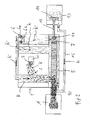
- FIGS. 1 and 2 now a generally designated 1 processing machine is shown, which has a machining tool 2 for machining a workpiece W.
- the machining tool 2 is known per se and will therefore not be described. It is cooled in a likewise known manner by means of a circulating in a coolant circuit K 'coolant K.
- the chips S lifted from the workpiece W by the machining tool 2 reach a chip conveyor 10, which in the case shown here is designed as a circulating link belt by being flushed through a machine bed flush to the chip conveyor 10.
- the larger chips S are transported away from the processing machine 1 by the chip conveyor 10 and arrive at a receiving container A.
- the smaller chips fall through the chip conveyor 10 and reach a machine bed 5 of the processing machine 1.
- the machine bed 5 also captures the coolant dripping from the processing tool 2 Purchase. To make this out of the tub-like To remove machine bed 5 and drive the coolant circuit is a coolant pump 6 with two coolant pump units 6a and 6b (see FIG. 2 ), which pumps off the coolant K from the machine bed 5. This coolant K is then returned to the machining tool 2.
- the processing machine 1 In the described embodiment of the processing machine 1 is - as best of FIG. 2 apparent - further provided that the processing machine 1 has a machine bed flushing, so that the coolant K is not only routed to the machining tool 2, but also flows through the machine bed 5 and thus rinses the chips S from the machine bed.
- the processing machine 1 has a suction pump 11, with which the swept by the chips S coolant K pumped out of the machine bed 5 and via a line 12 a separator 13, in which the chips S from the Coolant K are separated, is supplied.
- the separator 13 may, for. B. a sieve 14, which is acted upon by the mixed with the chips S coolant K, in which case the chips S are retained in the sieve 14 and the coolant K is cleaned so.
- This cleaned coolant K is again returned to the machine bed 5 via another line 15.
- a layering of the not covered by the chip conveyor 10 chips S in the machine bed 5 and concomitantly clogging of the chip conveyor 10 and / or the coolant pump 6 upstream separation unit 7 is counteracted.
- the time between two cleaning intervals is thereby significantly increased, which counteracts machine downtime.
- the return of the purified coolant K via the further line 15 in the machine bed 5 has the advantage that in this way the concentration of the chips S in the machine bed 5 located in the coolant K is reduced because this coolant-chips mixture diluted by supplying the purified coolant K. becomes.
- a processing machine 1 is formed by the measures described, in which not only the larger of the costs incurred in the machining process chips S are transported away from the chip conveyor 10 in an advantageous manner.
Landscapes
- Engineering & Computer Science (AREA)
- Mechanical Engineering (AREA)
- Chemical & Material Sciences (AREA)
- Chemical Kinetics & Catalysis (AREA)
- Auxiliary Devices For Machine Tools (AREA)
Description
- Die Erfindung betrifft eine Bearbeitungsmaschine zur Bearbeitung eines Werkstücks mit einem spanenden Bearbeitungswerkzeug, wobei zumindest dem Bearbeitungswerkzeug ein einen von einer Kühlmittelpumpe angetriebenen Kühlmittelkreislauf durchströmendes Kühlmittel zurückgeführt ist, die einen Späneförderer zum Abtransport eines Anteils der beim spanenden Bearbeitungsprozess des Werkstücks auftretenden Späne, ein unterhalb des Späneförderers angeordnetes Maschinenbett, in welchem ein Anteil der beim Bearbeitungsprozess des Werkstücks entstanden und nicht vom Späneförderer abtransportierten Späne und das Kühlmittel aufnehmbar ist, und eine Kühlmittelpumpe sowie eine dieser im Kühlmittelkreislauf vorgeschaltete Trenneinheit, mittels derer das im Maschinenbett befindliche Kühlmittel durch die Trenneinrichtung ansaugbar ist, aufweist.
- Eine derartige Bearbeitungsmaschine ist bekannt und dient zur spanenden Bearbeitung eines Werkstücks mittels eines spanabhebenden Bearbeitungswerkzeugs. Die dabei anfallenden Späne werden zu dem Späneförderer gespült und von diesem aus der Bearbeitungsmaschine abtransportiert. Hierbei tritt das Problem auf, dass kleine oder kleinere Späne vom Späneförderer nicht abtransportiert werden, da sie z. B. durch die Glieder des Späneförderers fallen, sich im darunter liegenden Maschinenbett der Bearbeitungsmaschine aufstauen und den Späneförderer dann verstopfen. Dies hat zur Folge, dass der Späneförderer in regelmäßigen Abständen gereinigt werden muss, was zu einem Maschinenstillstand und somit zu Ausfallzeiten der Bearbeitungsmaschine führt.
- Des weiteren verstopfen diese Späne die Trenneinheit im Kühlmittelkreislauf der Bearbeitungsmaschine, welche vor den Kühlmittelkreislauf bewirkenden Kühlmittelpumpen angeordnet ist, um diese vor den ihm Kühlmittel befindlichen Spänen zu schützen. Die Kühlmittelpumpen können dann nicht mehr die erforderliche Menge des Kühlmittels umwälzen. Da nicht mehr eine hinreichende Menge des Kühlmittels aus dem Maschinenbett abgeführt werden kann, droht die Gefahr, dass das im Maschinenbett befindliche Kühlmittel überläuft. Gehen die Verstopfungen der Trenneinheit über ein bestimmtes Maß hinaus, so schalten sich Kühlmittelpumpen aus Sicherheitsgründen ab, was wiederum zu einem Maschinenstillstand führt.
- Die
DE 20 2009 009 535 U1 beschreibt eine Vorrichtung zur Aufbereitung von Kühlschmierstoffen und Spänen für Werkzeugmaschinen. Diese weist einen Behälter zur Aufnahme des unbehandelten Gemisches aus Kühlschmierflüssigkeit und Feststoffen, einen in diesem Behälter installierten Endlosförderer für einen Abtransport der gesammelten Feststoffe aus dem Behälter sowie eine ebenfalls in diesem Behälter angeordneten Filtriereinheit zum Trennen der Kühlschmierflüssigkeit von den Feststoffen auf. Es ist vorgesehen, dass die Filtriereinheit mobil ausgebildet und als Einschub in den Behälter oberhalb eines Untertrums des Endlosförderers positionierbar ist. Hierdurch soll ein Verstopfen der nachgeordneten Filter durch Verschmutzungen im Kühlmittel vermieden werden. Die Ausbildung der Filtriereinheit als eigenständige Baugruppe bewirkt, dass die Filtriereinheit auf einfachste Weise aus der Vorrichtung herausgenommen, gereinigt und anschließend wieder an ihren ursprünglichen Platz in der Vorrichtung eingeschoben werden kann. - Die
DE 87 17 994 U1 beschreibt eine Reinigungsvorrichtung zum Abscheiden von Werkstückspänen oder ähnlicher Feststoffpartikel bei spanabhebenden Werkzeugmaschinen, wobei die die Werkstückspäne transportierende Flüssigkeit in einem zumindest einen Filter und wenigstens eine Umwälzpumpe aufweisenden Kreislauf geführt ist. Die Vorrichtung besitzt zwei wechselweise in Filterfunktion umschaltbare Filtereinrichtungen, wobei mittels einer Strömungsumkehr-Einrichtung die Durchströmungsrichtung der jeweiligen Filtereinrichtungen umkehrbar ist. Vor der Abströmseite wenigstens einer jeweils in Filterfunktion befindlichen Filtereinrichtung ist eine Flüssigkeitsführung zum Rückspülen und Reinigen zumindest einer jeweils anderen Filtereinrichtung vorgesehen. - Die
DE 31 27 440 C2 beschreibt eine Vorrichtung zum Reinigen und Rückführen von bei spangebender Metallbearbeitung den Spänen anhaftenden Kühlschmierstoff. Die Vorrichtung weist ein endloses, umlaufendes Stahlscharnierband in einem als Späneförderer ausgebildeten Vollkastengerüst auf, das aus einem waagrechten Flachkastenteil und einem kastenartigen Aufsteigeteil besteht, welches am oberen Ende zum Abwerfen der Späne offen ist. Des weiteren weist die Vorrichtung einen Schmutzflüssigkeitsbehälter und einen diesem zugeordneten Unterdruckfilter zum Reinigen des Kühlschmierstoffes von feinen Spänen sowie einen Regenerationstank, in den der gereinigte Kühlschmierstoff mittels einer Pumpe förderbar ist, auf. - Die
JP 2008-012 603 A - Die
EP 1 291 059 B1 beschreibt eine Vorrichtung zum Separieren und Austragen von Spänen, die einen Sammelbehälter aufweist, der im wesentlichen aus einem ersten, zur Aufnahme einer Arbeitsflüssigkeit geeigneten Kastenteil und einem sich daran anschließenden und unter einer Neigung ansteigenden zweiten Kastenteil mit einer oberhalb des Flüssigkeitsspiegels gelegenen Abwurfstelle besteht. Sie besitzt des weiteren einen Siebkasten, der beim Betrieb der Vorrichtung in die Arbeitsflüssigkeit im ersten Kastenteil des Behälters einbauchend angeordnet und mit einem Filter und/oder Siebmittel versehen ist. Des weiteren ist ein Späneförderer mit einem Förderorgan vorgesehen, welche im Betrieb der Vorrichtung die Späne zu der Abwurfstelle fördert. - Die
EP 2 168 715 A1 beschreibt eine gattungsgemäße Bearbeitungsmaschine, die ein öl-gekühltes Bearbeitungswerkzeug zur Bearbeitung eines Werkstücks aufweist. Das mit Spänen und sonstigen Verunreinigungen durchsetzte Öl läuft zu einem durchlöcherten Behälter, in dem die groben Späne aufgefangen werden. Unter diesem Behälter ist ein weiterer Behälter oder ein Späneförderer angeordnet, welche im Wesentlichen dazu dienen, aus dem Öl diejenigen Bestandteile, die den vorgenannten perforierten Behälter durchlaufen konnten, in einem Maße abzuscheiden, dass das in das Maschinenbett gelangende Öl nurmehr sehr kleine Verunreinigungen aufweist. Dieses Öl wird dann von einer Pumpe aus dem Maschinenbett abgesaugt und einer Reinigungseinrichtung zugeführt, dort gereinigt und anschließend wieder der Bearbeitungsmaschine zugeführt. - Es ist Aufgabe der vorliegenden Erfindung, eine Bearbeitungsmaschine der eingangs genannten Art derart weiterzubilden, dass eine verbesserte Abfuhr der beim Bearbeitungsprozess auftretenden Späne aus dem Maschinenbett erreicht wird.
- Diese Aufgabe wird erfindungsgemäß dadurch gelöst, dass die Bearbeitungsmaschine eine Absaugpumpe zum Absaugen eines Teils des im Maschinenbett befindlichen, mit Spänen durchsetzten Kühlmittels, sowie eine Trenneinrichtung zu der das von der Absaugpumpe abgesaugte Kühlmittel über eine Leitung führbar ist, aufweist, dass die parallel zu der den Kühlmittelkreislauf antreibenden Kühlmittelpumpe arbeitende Absaugpumpe sowie die Trenneinrichtung außerhalb des Kühlmittelkreislaufs angeordnet sind, und dass die Trenneinrichtung aus dem abgesaugten Kühlmittel zumindest einen Anteil der darin befindlichen Späne abgetrennt, und dass das derart gereinigte Kühlmittel durch eine weitere Leitung dem Kühlmittelkreislauf wieder zugeführt ist.
- Durch die erfindungsgemäßen Maßnahmen wird in vorteilhafter Art und Weise eine Bearbeitungsmaschine geschaffen, welche sich dadurch auszeichnet, dass nicht nur der vom Späneförderer erfasste Anteil der beim spanenden Bearbeitungsprozess des Werkstücks durch das spanende Werkzeug anfallenden Späne aus der Bearbeitungsmaschine abtransportiert wird. Vielmehr erlauben die beschriebenen Maßnahmen in vorteilhafter Art und Weise auch den Abtransport zumindest eines Anteils der nicht vom Späneförderer erfassten und in das Maschinenbett der erfindungsgemäßen Bearbeitungsmaschine fallenden Späne. Hierdurch wird einem Anstauen dieser Späne im Maschinenbett entgegengewirkt, so dass die Gefahr einer Verstopfung des Späneförderers und/oder der vor der Kühlmittelpumpe angeordneten Trenneinheit durch diese Späne entgegengewirkt wird. Der Späneförderer, die Trenneinheit und/oder das Maschinenbett der erfindungsgemäßen Bearbeitungsmaschine müssen daher in viel größeren Zeitabständen gereinigt werden, was in vorteilhafter Art und Weise die Maschinenstillstandszeiten reduziert.
- Eine vorteilhafte Weiterbildung der Erfindung sieht vor, die weitere Leitung in das Maschinenbett mündet, so dass das gereinigte Kühlmittel in das Maschinenbett der Bearbeitungsmaschine zurückgeführt wird. Eine derartige Maßnahme besitzt den Vorteil, dass das im Maschinenbett befindliche Kühlmittel-Späne-Gemisch durch die Zufuhr vom gereinigten Kühlmittel "verdünnt" wird. Die Späne-Konzentration in dem von der Absaugpumpe aus dem Maschinenbett abgesaugten Kühlmittels wird dadurch verringert, was zu einer geringen Belastung der Absaugpumpe und somit zu einer längeren Lebensdauer derselben führt.
- Eine weitere vorteilhafte Weiterbildung der Erfindung sieht vor, dass die weitere Leitung im Bereich des der Absaugpumpe entgegengesetzten Endes des Maschinenbetts in dieses mündet. Eine derartige Maßnahme besitzt den Vorteil, dass hierdurch das gereinigte Kühlmittel während seines gesamten Wegs zur Absaugpumpe eine Verringerung der Konzentration der Späne im Kühlmittel bewirken kann.
- Eine weitere vorteilhafte Weiterbildung der Erfindung sieht vor, dass die erfindungsgemäße Bearbeitungsmaschine eine Maschinenbettspülung aufweist. Eine derartige Maßnahme besitzt den Vorteil, dass hierdurch eine vergrößerte Abfuhr der Späne aus der Bearbeitungsmaschine erzielbar ist.
- Weitere vorteilhafte Weiterbildungen der Erfindung sind Gegenstand der Unteransprüche.
- Weitere Einzelheiten und Vorteile der Erfindung sind dem Ausführungsbeispiel zu entnehmen, das im folgenden anhand der Figuren beschrieben wird. Es zeigen:
- Figur 1:
- eine Seitenansicht eines Ausführungsbeispiels einer Bearbeitungsmaschine, und
- Figur 2:
- eine Draufsicht auf das Ausführungsbeispiel der
Figur 1 . - In den
Figuren 1 und2 ist nun eine allgemein mit 1 bezeichnete Bearbeitungsmaschine dargestellt, die ein Bearbeitungswerkzeug 2 zur spanenden Bearbeitung eines Werkstücks W besitzt. Das Bearbeitungswerkzeug 2 ist an und für sich bekannt und wird daher nicht mehr beschrieben. Es wird in ebenfalls bekannter Art und Weise mittels eines in einem Kühlmittelkreislauf K' umlaufenden Kühlmittels K gekühlt. Die vom Bearbeitungswerkzeug 2 vom Werkstück W abgehobenen Späne S gelangen zu einem Späneförderer 10, der im hier gezeigten Fall als ein umlaufendes Gliederband ausgebildet ist, indem sie durch eine MaschinenbettSpülung zum Späneförderer 10 hingespült werden. Die größeren Späne S werden durch den Späneförderer 10 aus der Bearbeitungsmaschine 1 abtransportiert und gelangen zu einem Aufnahmebehälter A. Die kleineren Späne fallen durch den Späneförderer 10 und gelangen zu einem Maschinenbett 5 der Bearbeitungsmaschine 1. Das Maschinenbett 5 fängt auch das vom Bearbeitungswerkzeug 2 herabtropfende Kühlmittel K auf. Um dieses aus dem wannenartig ausgebildeten Maschinenbett 5 zu entfernen und den Kühlmittelkreislauf anzutreiben, ist eine Kühlmittelpumpe 6 mit zwei Kühlmittelpumpeneinheiten 6a und 6b (sieheFigur 2 ) vorgesehen, welche das Kühlmittel K aus dem Maschinenbett 5 abpumpt. Dieses Kühlmittel K wird dann wieder dem Bearbeitungswerkzeug 2 zugeführt. Bei dem beschriebenen Ausführungsbeispiel der Bearbeitungsmaschine 1 ist - wie am besten ausFigur 2 ersichtlich - des weiteren vorgesehen, dass die Bearbeitungsmaschine 1 eine Maschinenbettspülung aufweist, so dass das Kühlmittel K nicht nur zum Bearbeitungswerkzeug 2 geleitet wird, sondern auch das Maschinebett 5 durchströmt und derart die Späne S aus dem Maschinenbett wegspült. Um die Kühlmittelpumpeneinheiten 6a und 6b der Kühlmittelpumpe 6 zu schützen, ist vor diesen eine vom Kühlmittel K durchströmbare, aber Späne S zurückhaltende Trenneinheit 7, z. B. ein Schott, ein Sieb oder ein Lochblech, angeordnet. Eine derartige Bearbeitungsmaschine 1 ist bekannt und muss daher nicht mehr weiter im Detail beschrieben werden. - Um nun für eine verbesserte Abfuhr der Späne S zu sorgen, ist bei der beschriebenen Bearbeitungsmaschine 1 vorgesehen, dass ein Teil des mit den Spänen S durchmischten Kühlmittels K dem Kühlmittelkreislauf K' vor der Trenneinheit 7 entnommen, die darin befindlichen Späne S aus dem Kühlmittel K zumindest teilweise entfernt und dieses Kühlmittel K wieder dem Kühlmittelkreislauf K' zugeführt wird. Eine derartige Maßnahme besitzt den Vorteil, dass durch diese Maßnahmen bei der Bearbeitungsmaschine 1 die Abfuhr der Späne S verbessert wird, da nun nicht mehr nur die durch den Späneförderer 10 abgeführten, größeren Späne S aus der Bearbeitungsmaschine 1 entfernt werden, sondern auch die nicht vom Späneförderer 10 erfassten Späne S aus dieser entfernt werden. Eine störende Ablagerung der Späne S im Maschinenbett 5, welche - wie eingangs beschrieben - dazu führt, dass das Maschinenbett 5, der Späneförderer 10 und/oder die Trenneinheit 7 verstopfen, wird somit vermieden. Es treten somit aus diesem Grund keine oder nur verringerte Maschinenausfallzeiten auf, da eine Reinigung des Späneförderers 10 und/oder der Trenneinheit 7 nun nicht oder nurmehr in größeren Abständen erforderlich ist.
- Diese Maßnahme wird bei dem beschriebenen Ausführungsbeispiel dadurch umgesetzt, dass die Bearbeitungsmaschine 1 eine Absaugpumpe 11 aufweist, mit der das von den Spänen S durchsetzte Kühlmittel K aus dem Maschinenbett 5 abgepumpt und über eine Leitung 12 einer Trenneinrichtung 13, in welcher die Späne S aus dem Kühlmittel K abgetrennt werden, zugeführt wird. Die Trenneinrichtung 13 kann z. B. ein Sieb 14 sein, welches mit dem mit den Spänen S durchmischten Kühlmittel K beaufschlagt wird, wobei dann die Späne S im Sieb 14 zurückgehalten werden und das Kühlmittel K derart gereinigt wird. Dieses derart gereinigte Kühlmittel K wird über eine weitere Leitung 15 wiederum zum Maschinenbett 5 zurückgeführt. Durch die beschriebenen Maßnahmen wird erreicht, dass aus der Bearbeitungsmaschine auf die nicht vom Späneförderer 10 nicht erfassten Späne S - zumindest zu einem hohen Anteil - abtransportiert werden. Einem Anschichten der nicht vom Späneförderer 10 erfassten Späne S im Maschinenbett 5 und damit einhergehend eine Verstopfung des Späneförderers 10 und/oder der der Kühlmittelpumpe 6 vorgeschalteten Trenneinheit 7 wird dadurch entgegengewirkt. Die Zeit zwischen zwei Reinigungsintervallen wird dadurch deutlich vergrößert, was Maschinenstillstandszeiten entgegenwirkt.
- Die Rückführung des gereinigten Kühlmittels K über die weitere Leitung 15 im Maschinenbett 5 besitzt den Vorteil, dass hierdurch die Konzentration der Späne S in dem im Maschinenbett 5 befindlichen Kühlmittel K verringert wird, da dieses Kühlmittel-Späne-Gemisch durch Zufuhr des gereinigten Kühlmittels K verdünnt wird. Vorzugsweise ist hierbei vorgesehen, dass die Rückführung des gereinigten Kühlmittels durch die weitere Leitung 15 an dem der Ansaugpumpe 11 gegenüberliegenden Ende des Maschinenbetts erfolgt.
- Es ist natürlich auch möglich, dass anstelle oder in Ergänzung zu dieser Rückführung ins Maschinenbett 5 das Kühlmittel K an anderer Stelle wieder in den Kühlmittelkreislauf eingespeist wird.
- Zusammenfassend ist festzuhalten, dass durch die beschriebenen Maßnahmen eine Bearbeitungsmaschine 1 ausgebildet wird, bei der in vorteilhafter Art und Weise nicht nur die größeren der beim Bearbeitungsprozess anfallenden Späne S vom Späneförderer 10 abtransportiert werden.
Claims (4)
- Bearbeitungsmaschine zur Bearbeitung eines Werkstücks (W) mit einem spanenden Bearbeitungswerkzeug (2), wobei zumindest dem Bearbeitungswerkzeug (2) ein einen von einer Kühlmittelpumpe (6) angetriebenen Kühlmittelkreislauf (K') durchströmendes Kühlmittel (K) zurückgeführt ist, die einen Späneförderer (10) zum Abtransport eines Anteils der beim spanenden Bearbeitungsprozess des Werkstücks (W) auftretenden Späne (S), ein unterhalb des Späneförderers (10) angeordnetes Maschinenbett (5), in welchem ein Anteil der beim Bearbeitungsprozess des Werkstücks (W) entstandenen und nicht vom Späneförderer (10) abtransportierten Späne (S) und das Kühlmittel (K) aufnehmbar ist, eine Kühlmittelpumpe (6; 6a, 6b) sowie eine dieser im Kühlmittelkreislauf (K') vorgeschaltete Trenneinheit (7), mittels derer das im Maschinenbett (5) befindliche Kühlmittel (K) durch die Trenneinheit (7) ansaugbar ist, aufweist, dadurch gekennzeichnet, dass die Bearbeitungsmaschine (1) eine Absaugpumpe (11) zum Absaugen eines Teils des im Maschinenbett befindlichen, mit Spänen (S) durchsetzten Kühlmittels (K), sowie eine Trenneinrichtung (13) zu der das von der Absaugpumpe (11) abgesaugte Kühlmittel (K) über eine Leitung (12) führbar ist, aufweist, dass die parallel zu der den Kühlmittelkreislauf (K') antreibenden Kühlmittelpumpe (6) arbeitende Absaugpumpe (11) sowie die Trenneinrichtung (13) außerhalb des Kühlmittelkreislaufs (K') angeordnet sind, und dass die Trenneinrichtung (13) aus dem abgesaugten Kühlmittel (K) zumindest einen Anteil der darin befindlichen Späne (S) abgetrennt, und dass das derart gereinigte Kühlmittel (K) durch eine weitere Leitung (15) dem Kühlmittelkreislauf zugeführt ist.
- Bearbeitungsmaschine nach Anspruch 1, dadurch gekennzeichnet, dass die Trenneinrichtung (13) ein Sieb (14) zur Abtrennung der Späne (S) aus dem Kühlmittel (K) besitzt.
- Bearbeitungsmaschine nach einem der vorangehenden Ansprüche, dadurch gekennzeichnet, dass die weitere Leitung (15) in das Maschinenbett (5) mündet.
- Bearbeitungsmaschine nach Anspruch 3, dadurch gekennzeichnet, dass die weitere Leitung (15) im Bereich des der Absaugpumpe (11) entgegengesetzten Endes des Maschinenbetts (5) in dieses mündet.
Applications Claiming Priority (2)
| Application Number | Priority Date | Filing Date | Title |
|---|---|---|---|
| DE202012004436U DE202012004436U1 (de) | 2012-05-08 | 2012-05-08 | Bearbeitungsmaschine |
| DE201210008900 DE102012008900B3 (de) | 2012-05-08 | 2012-05-08 | Bearbeitungsmaschine |
Publications (2)
| Publication Number | Publication Date |
|---|---|
| EP2662183A1 EP2662183A1 (de) | 2013-11-13 |
| EP2662183B1 true EP2662183B1 (de) | 2015-04-08 |
Family
ID=48430407
Family Applications (1)
| Application Number | Title | Priority Date | Filing Date |
|---|---|---|---|
| EP13002415.1A Not-in-force EP2662183B1 (de) | 2012-05-08 | 2013-05-06 | Bearbeitungsmaschine |
Country Status (1)
| Country | Link |
|---|---|
| EP (1) | EP2662183B1 (de) |
Cited By (1)
| Publication number | Priority date | Publication date | Assignee | Title |
|---|---|---|---|---|
| US20240087158A1 (en) * | 2021-05-24 | 2024-03-14 | Dmg Mori Co., Ltd. | Information processing device, and program |
Families Citing this family (4)
| Publication number | Priority date | Publication date | Assignee | Title |
|---|---|---|---|---|
| CN103921164B (zh) * | 2014-03-31 | 2016-09-14 | 温州市兴泰科技有限公司 | 钢管切割废液收集装置 |
| WO2018188703A1 (en) * | 2017-04-11 | 2018-10-18 | Accustrip Aps | Method by filtration of coolant and a filtration system |
| CN108127163B (zh) * | 2017-12-21 | 2019-03-15 | 重庆千乔机电有限公司 | 建材切割装置 |
| CN110961736B (zh) * | 2020-01-04 | 2021-02-26 | 共和精英塑胶五金制品(深圳)有限公司 | 一种线切割机冷却液的铁屑清理装置 |
Family Cites Families (8)
| Publication number | Priority date | Publication date | Assignee | Title |
|---|---|---|---|---|
| DE3127440A1 (de) | 1981-07-11 | 1983-03-03 | MDS Mannesmann Demag Sack GmbH, 4000 Düsseldorf | Kuehlschmierstoff-trenn- und reinigungsvorrichtung |
| DE3743508C2 (de) | 1987-12-22 | 1993-12-23 | D & S Foerdertechnik Gmbh | Reinigungsvorrichtung |
| US6612314B2 (en) * | 2001-06-29 | 2003-09-02 | Jack R. Bratten | Process for removing oil containing machining fluid from machined chips |
| DE10144157C1 (de) | 2001-09-07 | 2003-02-20 | Interlit Joistgen Gmbh | Vorrichtung zum Separieren und Austragen von Spänen |
| US7410569B1 (en) * | 2005-11-18 | 2008-08-12 | Turhan A. Tilev | Filtration system for metalworking fluids |
| JP2008012603A (ja) | 2006-07-03 | 2008-01-24 | Toyota Motor Corp | クーラント浄化装置 |
| EP2168715A1 (de) * | 2008-09-26 | 2010-03-31 | Tornos SA | System zur Aufbereitung von Bearbeitungsöl |
| DE202009009535U1 (de) | 2009-07-13 | 2009-09-17 | Deckel Maho Pfronten Gmbh | Vorrichtung zur Aufbereitung von Kühlschmierstoff |
-
2013
- 2013-05-06 EP EP13002415.1A patent/EP2662183B1/de not_active Not-in-force
Cited By (2)
| Publication number | Priority date | Publication date | Assignee | Title |
|---|---|---|---|---|
| US20240087158A1 (en) * | 2021-05-24 | 2024-03-14 | Dmg Mori Co., Ltd. | Information processing device, and program |
| US12400354B2 (en) * | 2021-05-24 | 2025-08-26 | Dmg Mori Co., Ltd. | Information processing device, and program |
Also Published As
| Publication number | Publication date |
|---|---|
| EP2662183A1 (de) | 2013-11-13 |
Similar Documents
| Publication | Publication Date | Title |
|---|---|---|
| EP2283908B1 (de) | Vorrichtung zur Aufbereitung von Kühlschmierstoff | |
| EP2662183B1 (de) | Bearbeitungsmaschine | |
| DE29519626U1 (de) | Reinigungsvorrichtung | |
| DE102004060950A1 (de) | Geschirrspülmaschine mit wartungsarmem Siebsystem | |
| DE60204500T2 (de) | Industrielle Filtrationsvorrichtung mit Anordung zur Abtrennung von Bearbeitungsspänen aus der Kühlflüssigkeit vor der Filtration | |
| DE10035725C2 (de) | Späneförderer | |
| EP1476275B1 (de) | Vorrichtung zur aufnahme und trennung von an werkzeugmaschinen anfallenden spaenen und kuehlfluessigkeit (ueberlauf) | |
| DE102012008900B3 (de) | Bearbeitungsmaschine | |
| EP2228114A1 (de) | Reinigungsanlage | |
| WO2001060493A1 (de) | Verfahren und vorrichtung zur reinigung von flüssigkeiten | |
| EP1291059B1 (de) | Vorrichtung zum Separieren und Austragen von Spänen | |
| DE3743508C2 (de) | Reinigungsvorrichtung | |
| DE202016101410U1 (de) | Kühlschmierstoffeinrichtung für eine Werkzeugmaschine | |
| DE202012004436U1 (de) | Bearbeitungsmaschine | |
| WO2003064106A1 (de) | Vorrichtung zum separieren und austragen von spänen und arbeitsflüssigkeit | |
| EP1375061B1 (de) | Vorrichtung zur Späneentsorgung | |
| DE102016104678B4 (de) | Kühlschmierstoffeinrichtung für eine Werkzeugmaschine | |
| DE202006009150U1 (de) | Filtervorrichtung für Kühlschmierflüssigkeit | |
| EP1270056B1 (de) | Filtervorrichtung für Flüssigkeiten, insbesondere für Kühlflüssigkeiten | |
| DE102012102203B4 (de) | Vorrichtung zur Reinigung eines Fluides | |
| WO2003031116A2 (de) | Vorrichtung zum abtransport von spänen und kühlflüssigkeit | |
| DE3823486C1 (de) | ||
| DE20110879U1 (de) | Filtervorrichtung für Flüssigkeiten, insbesondere für Kühlflüssigkeiten | |
| DE20007698U1 (de) | Filter zum Reinigen von Emulsionen aus der spangebenden Metallbearbeitung | |
| DE202010002569U1 (de) | Späneförderer für Maschinen |
Legal Events
| Date | Code | Title | Description |
|---|---|---|---|
| PUAI | Public reference made under article 153(3) epc to a published international application that has entered the european phase |
Free format text: ORIGINAL CODE: 0009012 |
|
| AK | Designated contracting states |
Kind code of ref document: A1 Designated state(s): AL AT BE BG CH CY CZ DE DK EE ES FI FR GB GR HR HU IE IS IT LI LT LU LV MC MK MT NL NO PL PT RO RS SE SI SK SM TR |
|
| AX | Request for extension of the european patent |
Extension state: BA ME |
|
| 17P | Request for examination filed |
Effective date: 20140506 |
|
| RBV | Designated contracting states (corrected) |
Designated state(s): AL AT BE BG CH CY CZ DE DK EE ES FI FR GB GR HR HU IE IS IT LI LT LU LV MC MK MT NL NO PL PT RO RS SE SI SK SM TR |
|
| 17Q | First examination report despatched |
Effective date: 20140627 |
|
| GRAP | Despatch of communication of intention to grant a patent |
Free format text: ORIGINAL CODE: EPIDOSNIGR1 |
|
| INTG | Intention to grant announced |
Effective date: 20141023 |
|
| GRAS | Grant fee paid |
Free format text: ORIGINAL CODE: EPIDOSNIGR3 |
|
| GRAA | (expected) grant |
Free format text: ORIGINAL CODE: 0009210 |
|
| AK | Designated contracting states |
Kind code of ref document: B1 Designated state(s): AL AT BE BG CH CY CZ DE DK EE ES FI FR GB GR HR HU IE IS IT LI LT LU LV MC MK MT NL NO PL PT RO RS SE SI SK SM TR |
|
| REG | Reference to a national code |
Ref country code: GB Ref legal event code: FG4D Free format text: NOT ENGLISH |
|
| REG | Reference to a national code |
Ref country code: CH Ref legal event code: EP |
|
| REG | Reference to a national code |
Ref country code: IE Ref legal event code: FG4D Free format text: LANGUAGE OF EP DOCUMENT: GERMAN |
|
| REG | Reference to a national code |
Ref country code: DE Ref legal event code: R096 Ref document number: 502013000519 Country of ref document: DE Effective date: 20150513 |
|
| REG | Reference to a national code |
Ref country code: AT Ref legal event code: REF Ref document number: 720155 Country of ref document: AT Kind code of ref document: T Effective date: 20150515 |
|
| REG | Reference to a national code |
Ref country code: NL Ref legal event code: VDEP Effective date: 20150408 |
|
| REG | Reference to a national code |
Ref country code: LT Ref legal event code: MG4D |
|
| PG25 | Lapsed in a contracting state [announced via postgrant information from national office to epo] |
Ref country code: NL Free format text: LAPSE BECAUSE OF FAILURE TO SUBMIT A TRANSLATION OF THE DESCRIPTION OR TO PAY THE FEE WITHIN THE PRESCRIBED TIME-LIMIT Effective date: 20150408 |
|
| PG25 | Lapsed in a contracting state [announced via postgrant information from national office to epo] |
Ref country code: ES Free format text: LAPSE BECAUSE OF FAILURE TO SUBMIT A TRANSLATION OF THE DESCRIPTION OR TO PAY THE FEE WITHIN THE PRESCRIBED TIME-LIMIT Effective date: 20150408 Ref country code: HR Free format text: LAPSE BECAUSE OF FAILURE TO SUBMIT A TRANSLATION OF THE DESCRIPTION OR TO PAY THE FEE WITHIN THE PRESCRIBED TIME-LIMIT Effective date: 20150408 Ref country code: PT Free format text: LAPSE BECAUSE OF FAILURE TO SUBMIT A TRANSLATION OF THE DESCRIPTION OR TO PAY THE FEE WITHIN THE PRESCRIBED TIME-LIMIT Effective date: 20150810 Ref country code: LT Free format text: LAPSE BECAUSE OF FAILURE TO SUBMIT A TRANSLATION OF THE DESCRIPTION OR TO PAY THE FEE WITHIN THE PRESCRIBED TIME-LIMIT Effective date: 20150408 Ref country code: FI Free format text: LAPSE BECAUSE OF FAILURE TO SUBMIT A TRANSLATION OF THE DESCRIPTION OR TO PAY THE FEE WITHIN THE PRESCRIBED TIME-LIMIT Effective date: 20150408 Ref country code: NO Free format text: LAPSE BECAUSE OF FAILURE TO SUBMIT A TRANSLATION OF THE DESCRIPTION OR TO PAY THE FEE WITHIN THE PRESCRIBED TIME-LIMIT Effective date: 20150708 |
|
| PG25 | Lapsed in a contracting state [announced via postgrant information from national office to epo] |
Ref country code: RS Free format text: LAPSE BECAUSE OF FAILURE TO SUBMIT A TRANSLATION OF THE DESCRIPTION OR TO PAY THE FEE WITHIN THE PRESCRIBED TIME-LIMIT Effective date: 20150408 Ref country code: LV Free format text: LAPSE BECAUSE OF FAILURE TO SUBMIT A TRANSLATION OF THE DESCRIPTION OR TO PAY THE FEE WITHIN THE PRESCRIBED TIME-LIMIT Effective date: 20150408 Ref country code: GR Free format text: LAPSE BECAUSE OF FAILURE TO SUBMIT A TRANSLATION OF THE DESCRIPTION OR TO PAY THE FEE WITHIN THE PRESCRIBED TIME-LIMIT Effective date: 20150709 Ref country code: IS Free format text: LAPSE BECAUSE OF FAILURE TO SUBMIT A TRANSLATION OF THE DESCRIPTION OR TO PAY THE FEE WITHIN THE PRESCRIBED TIME-LIMIT Effective date: 20150808 |
|
| REG | Reference to a national code |
Ref country code: DE Ref legal event code: R097 Ref document number: 502013000519 Country of ref document: DE |
|
| PG25 | Lapsed in a contracting state [announced via postgrant information from national office to epo] |
Ref country code: DK Free format text: LAPSE BECAUSE OF FAILURE TO SUBMIT A TRANSLATION OF THE DESCRIPTION OR TO PAY THE FEE WITHIN THE PRESCRIBED TIME-LIMIT Effective date: 20150408 Ref country code: MC Free format text: LAPSE BECAUSE OF FAILURE TO SUBMIT A TRANSLATION OF THE DESCRIPTION OR TO PAY THE FEE WITHIN THE PRESCRIBED TIME-LIMIT Effective date: 20150408 Ref country code: IT Free format text: LAPSE BECAUSE OF FAILURE TO SUBMIT A TRANSLATION OF THE DESCRIPTION OR TO PAY THE FEE WITHIN THE PRESCRIBED TIME-LIMIT Effective date: 20150408 Ref country code: EE Free format text: LAPSE BECAUSE OF FAILURE TO SUBMIT A TRANSLATION OF THE DESCRIPTION OR TO PAY THE FEE WITHIN THE PRESCRIBED TIME-LIMIT Effective date: 20150408 |
|
| PLBE | No opposition filed within time limit |
Free format text: ORIGINAL CODE: 0009261 |
|
| STAA | Information on the status of an ep patent application or granted ep patent |
Free format text: STATUS: NO OPPOSITION FILED WITHIN TIME LIMIT |
|
| REG | Reference to a national code |
Ref country code: IE Ref legal event code: MM4A |
|
| REG | Reference to a national code |
Ref country code: FR Ref legal event code: ST Effective date: 20160129 |
|
| PG25 | Lapsed in a contracting state [announced via postgrant information from national office to epo] |
Ref country code: RO Free format text: LAPSE BECAUSE OF NON-PAYMENT OF DUE FEES Effective date: 20150408 Ref country code: SK Free format text: LAPSE BECAUSE OF FAILURE TO SUBMIT A TRANSLATION OF THE DESCRIPTION OR TO PAY THE FEE WITHIN THE PRESCRIBED TIME-LIMIT Effective date: 20150408 Ref country code: PL Free format text: LAPSE BECAUSE OF FAILURE TO SUBMIT A TRANSLATION OF THE DESCRIPTION OR TO PAY THE FEE WITHIN THE PRESCRIBED TIME-LIMIT Effective date: 20150408 Ref country code: CZ Free format text: LAPSE BECAUSE OF FAILURE TO SUBMIT A TRANSLATION OF THE DESCRIPTION OR TO PAY THE FEE WITHIN THE PRESCRIBED TIME-LIMIT Effective date: 20150408 |
|
| 26N | No opposition filed |
Effective date: 20160111 |
|
| PG25 | Lapsed in a contracting state [announced via postgrant information from national office to epo] |
Ref country code: IE Free format text: LAPSE BECAUSE OF NON-PAYMENT OF DUE FEES Effective date: 20150506 |
|
| PG25 | Lapsed in a contracting state [announced via postgrant information from national office to epo] |
Ref country code: FR Free format text: LAPSE BECAUSE OF NON-PAYMENT OF DUE FEES Effective date: 20150608 Ref country code: SI Free format text: LAPSE BECAUSE OF FAILURE TO SUBMIT A TRANSLATION OF THE DESCRIPTION OR TO PAY THE FEE WITHIN THE PRESCRIBED TIME-LIMIT Effective date: 20150408 |
|
| PGFP | Annual fee paid to national office [announced via postgrant information from national office to epo] |
Ref country code: DE Payment date: 20160418 Year of fee payment: 4 |
|
| PG25 | Lapsed in a contracting state [announced via postgrant information from national office to epo] |
Ref country code: MT Free format text: LAPSE BECAUSE OF FAILURE TO SUBMIT A TRANSLATION OF THE DESCRIPTION OR TO PAY THE FEE WITHIN THE PRESCRIBED TIME-LIMIT Effective date: 20150408 |
|
| REG | Reference to a national code |
Ref country code: CH Ref legal event code: PL |
|
| PG25 | Lapsed in a contracting state [announced via postgrant information from national office to epo] |
Ref country code: CH Free format text: LAPSE BECAUSE OF NON-PAYMENT OF DUE FEES Effective date: 20160531 Ref country code: LI Free format text: LAPSE BECAUSE OF NON-PAYMENT OF DUE FEES Effective date: 20160531 |
|
| PG25 | Lapsed in a contracting state [announced via postgrant information from national office to epo] |
Ref country code: BG Free format text: LAPSE BECAUSE OF FAILURE TO SUBMIT A TRANSLATION OF THE DESCRIPTION OR TO PAY THE FEE WITHIN THE PRESCRIBED TIME-LIMIT Effective date: 20150408 Ref country code: HU Free format text: LAPSE BECAUSE OF FAILURE TO SUBMIT A TRANSLATION OF THE DESCRIPTION OR TO PAY THE FEE WITHIN THE PRESCRIBED TIME-LIMIT; INVALID AB INITIO Effective date: 20130506 |
|
| PG25 | Lapsed in a contracting state [announced via postgrant information from national office to epo] |
Ref country code: CY Free format text: LAPSE BECAUSE OF FAILURE TO SUBMIT A TRANSLATION OF THE DESCRIPTION OR TO PAY THE FEE WITHIN THE PRESCRIBED TIME-LIMIT Effective date: 20150408 Ref country code: SE Free format text: LAPSE BECAUSE OF FAILURE TO SUBMIT A TRANSLATION OF THE DESCRIPTION OR TO PAY THE FEE WITHIN THE PRESCRIBED TIME-LIMIT Effective date: 20150408 |
|
| PG25 | Lapsed in a contracting state [announced via postgrant information from national office to epo] |
Ref country code: BE Free format text: LAPSE BECAUSE OF NON-PAYMENT OF DUE FEES Effective date: 20150531 |
|
| PG25 | Lapsed in a contracting state [announced via postgrant information from national office to epo] |
Ref country code: TR Free format text: LAPSE BECAUSE OF FAILURE TO SUBMIT A TRANSLATION OF THE DESCRIPTION OR TO PAY THE FEE WITHIN THE PRESCRIBED TIME-LIMIT Effective date: 20150408 |
|
| PG25 | Lapsed in a contracting state [announced via postgrant information from national office to epo] |
Ref country code: LU Free format text: LAPSE BECAUSE OF NON-PAYMENT OF DUE FEES Effective date: 20150506 |
|
| REG | Reference to a national code |
Ref country code: DE Ref legal event code: R119 Ref document number: 502013000519 Country of ref document: DE |
|
| GBPC | Gb: european patent ceased through non-payment of renewal fee |
Effective date: 20170506 |
|
| PG25 | Lapsed in a contracting state [announced via postgrant information from national office to epo] |
Ref country code: DE Free format text: LAPSE BECAUSE OF NON-PAYMENT OF DUE FEES Effective date: 20171201 Ref country code: GB Free format text: LAPSE BECAUSE OF NON-PAYMENT OF DUE FEES Effective date: 20170506 |
|
| PG25 | Lapsed in a contracting state [announced via postgrant information from national office to epo] |
Ref country code: SM Free format text: LAPSE BECAUSE OF FAILURE TO SUBMIT A TRANSLATION OF THE DESCRIPTION OR TO PAY THE FEE WITHIN THE PRESCRIBED TIME-LIMIT Effective date: 20150408 |
|
| PG25 | Lapsed in a contracting state [announced via postgrant information from national office to epo] |
Ref country code: MK Free format text: LAPSE BECAUSE OF FAILURE TO SUBMIT A TRANSLATION OF THE DESCRIPTION OR TO PAY THE FEE WITHIN THE PRESCRIBED TIME-LIMIT Effective date: 20150408 |
|
| PG25 | Lapsed in a contracting state [announced via postgrant information from national office to epo] |
Ref country code: AL Free format text: LAPSE BECAUSE OF FAILURE TO SUBMIT A TRANSLATION OF THE DESCRIPTION OR TO PAY THE FEE WITHIN THE PRESCRIBED TIME-LIMIT Effective date: 20150408 |
|
| REG | Reference to a national code |
Ref country code: AT Ref legal event code: MM01 Ref document number: 720155 Country of ref document: AT Kind code of ref document: T Effective date: 20180506 |
|
| PG25 | Lapsed in a contracting state [announced via postgrant information from national office to epo] |
Ref country code: AT Free format text: LAPSE BECAUSE OF NON-PAYMENT OF DUE FEES Effective date: 20180506 |