WO2022259838A1 - 高強度鋼板およびその製造方法 - Google Patents
高強度鋼板およびその製造方法 Download PDFInfo
- Publication number
- WO2022259838A1 WO2022259838A1 PCT/JP2022/020893 JP2022020893W WO2022259838A1 WO 2022259838 A1 WO2022259838 A1 WO 2022259838A1 JP 2022020893 W JP2022020893 W JP 2022020893W WO 2022259838 A1 WO2022259838 A1 WO 2022259838A1
- Authority
- WO
- WIPO (PCT)
- Prior art keywords
- less
- steel sheet
- content
- temperature
- kam
- Prior art date
- Legal status (The legal status is an assumption and is not a legal conclusion. Google has not performed a legal analysis and makes no representation as to the accuracy of the status listed.)
- Ceased
Links
Classifications
-
- C—CHEMISTRY; METALLURGY
- C21—METALLURGY OF IRON
- C21D—MODIFYING THE PHYSICAL STRUCTURE OF FERROUS METALS; GENERAL DEVICES FOR HEAT TREATMENT OF FERROUS OR NON-FERROUS METALS OR ALLOYS; MAKING METAL MALLEABLE, e.g. BY DECARBURISATION OR TEMPERING
- C21D9/00—Heat treatment, e.g. annealing, hardening, quenching or tempering, adapted for particular articles; Furnaces therefor
- C21D9/46—Heat treatment, e.g. annealing, hardening, quenching or tempering, adapted for particular articles; Furnaces therefor for sheet metals
-
- C—CHEMISTRY; METALLURGY
- C21—METALLURGY OF IRON
- C21D—MODIFYING THE PHYSICAL STRUCTURE OF FERROUS METALS; GENERAL DEVICES FOR HEAT TREATMENT OF FERROUS OR NON-FERROUS METALS OR ALLOYS; MAKING METAL MALLEABLE, e.g. BY DECARBURISATION OR TEMPERING
- C21D1/00—General methods or devices for heat treatment, e.g. annealing, hardening, quenching or tempering
- C21D1/18—Hardening; Quenching with or without subsequent tempering
-
- C—CHEMISTRY; METALLURGY
- C21—METALLURGY OF IRON
- C21D—MODIFYING THE PHYSICAL STRUCTURE OF FERROUS METALS; GENERAL DEVICES FOR HEAT TREATMENT OF FERROUS OR NON-FERROUS METALS OR ALLOYS; MAKING METAL MALLEABLE, e.g. BY DECARBURISATION OR TEMPERING
- C21D1/00—General methods or devices for heat treatment, e.g. annealing, hardening, quenching or tempering
- C21D1/18—Hardening; Quenching with or without subsequent tempering
- C21D1/25—Hardening, combined with annealing between 300 degrees Celsius and 600 degrees Celsius, i.e. heat refining ("Vergüten")
-
- C—CHEMISTRY; METALLURGY
- C21—METALLURGY OF IRON
- C21D—MODIFYING THE PHYSICAL STRUCTURE OF FERROUS METALS; GENERAL DEVICES FOR HEAT TREATMENT OF FERROUS OR NON-FERROUS METALS OR ALLOYS; MAKING METAL MALLEABLE, e.g. BY DECARBURISATION OR TEMPERING
- C21D1/00—General methods or devices for heat treatment, e.g. annealing, hardening, quenching or tempering
- C21D1/78—Combined heat-treatments not provided for above
-
- C—CHEMISTRY; METALLURGY
- C21—METALLURGY OF IRON
- C21D—MODIFYING THE PHYSICAL STRUCTURE OF FERROUS METALS; GENERAL DEVICES FOR HEAT TREATMENT OF FERROUS OR NON-FERROUS METALS OR ALLOYS; MAKING METAL MALLEABLE, e.g. BY DECARBURISATION OR TEMPERING
- C21D6/00—Heat treatment of ferrous alloys
- C21D6/001—Heat treatment of ferrous alloys containing Ni
-
- C—CHEMISTRY; METALLURGY
- C21—METALLURGY OF IRON
- C21D—MODIFYING THE PHYSICAL STRUCTURE OF FERROUS METALS; GENERAL DEVICES FOR HEAT TREATMENT OF FERROUS OR NON-FERROUS METALS OR ALLOYS; MAKING METAL MALLEABLE, e.g. BY DECARBURISATION OR TEMPERING
- C21D6/00—Heat treatment of ferrous alloys
- C21D6/002—Heat treatment of ferrous alloys containing Cr
-
- C—CHEMISTRY; METALLURGY
- C21—METALLURGY OF IRON
- C21D—MODIFYING THE PHYSICAL STRUCTURE OF FERROUS METALS; GENERAL DEVICES FOR HEAT TREATMENT OF FERROUS OR NON-FERROUS METALS OR ALLOYS; MAKING METAL MALLEABLE, e.g. BY DECARBURISATION OR TEMPERING
- C21D6/00—Heat treatment of ferrous alloys
- C21D6/005—Heat treatment of ferrous alloys containing Mn
-
- C—CHEMISTRY; METALLURGY
- C21—METALLURGY OF IRON
- C21D—MODIFYING THE PHYSICAL STRUCTURE OF FERROUS METALS; GENERAL DEVICES FOR HEAT TREATMENT OF FERROUS OR NON-FERROUS METALS OR ALLOYS; MAKING METAL MALLEABLE, e.g. BY DECARBURISATION OR TEMPERING
- C21D6/00—Heat treatment of ferrous alloys
- C21D6/007—Heat treatment of ferrous alloys containing Co
-
- C—CHEMISTRY; METALLURGY
- C21—METALLURGY OF IRON
- C21D—MODIFYING THE PHYSICAL STRUCTURE OF FERROUS METALS; GENERAL DEVICES FOR HEAT TREATMENT OF FERROUS OR NON-FERROUS METALS OR ALLOYS; MAKING METAL MALLEABLE, e.g. BY DECARBURISATION OR TEMPERING
- C21D6/00—Heat treatment of ferrous alloys
- C21D6/008—Heat treatment of ferrous alloys containing Si
-
- C—CHEMISTRY; METALLURGY
- C21—METALLURGY OF IRON
- C21D—MODIFYING THE PHYSICAL STRUCTURE OF FERROUS METALS; GENERAL DEVICES FOR HEAT TREATMENT OF FERROUS OR NON-FERROUS METALS OR ALLOYS; MAKING METAL MALLEABLE, e.g. BY DECARBURISATION OR TEMPERING
- C21D7/00—Modifying the physical properties of iron or steel by deformation
- C21D7/02—Modifying the physical properties of iron or steel by deformation by cold working
- C21D7/10—Modifying the physical properties of iron or steel by deformation by cold working of the whole cross-section, e.g. of concrete reinforcing bars
-
- C—CHEMISTRY; METALLURGY
- C21—METALLURGY OF IRON
- C21D—MODIFYING THE PHYSICAL STRUCTURE OF FERROUS METALS; GENERAL DEVICES FOR HEAT TREATMENT OF FERROUS OR NON-FERROUS METALS OR ALLOYS; MAKING METAL MALLEABLE, e.g. BY DECARBURISATION OR TEMPERING
- C21D8/00—Modifying the physical properties of ferrous metals or ferrous alloys by deformation combined with, or followed by, heat treatment
- C21D8/02—Modifying the physical properties of ferrous metals or ferrous alloys by deformation combined with, or followed by, heat treatment during manufacturing of plates or strips
-
- C—CHEMISTRY; METALLURGY
- C21—METALLURGY OF IRON
- C21D—MODIFYING THE PHYSICAL STRUCTURE OF FERROUS METALS; GENERAL DEVICES FOR HEAT TREATMENT OF FERROUS OR NON-FERROUS METALS OR ALLOYS; MAKING METAL MALLEABLE, e.g. BY DECARBURISATION OR TEMPERING
- C21D8/00—Modifying the physical properties of ferrous metals or ferrous alloys by deformation combined with, or followed by, heat treatment
- C21D8/02—Modifying the physical properties of ferrous metals or ferrous alloys by deformation combined with, or followed by, heat treatment during manufacturing of plates or strips
- C21D8/0221—Modifying the physical properties of ferrous metals or ferrous alloys by deformation combined with, or followed by, heat treatment during manufacturing of plates or strips characterised by the working steps
- C21D8/0226—Hot rolling
-
- C—CHEMISTRY; METALLURGY
- C21—METALLURGY OF IRON
- C21D—MODIFYING THE PHYSICAL STRUCTURE OF FERROUS METALS; GENERAL DEVICES FOR HEAT TREATMENT OF FERROUS OR NON-FERROUS METALS OR ALLOYS; MAKING METAL MALLEABLE, e.g. BY DECARBURISATION OR TEMPERING
- C21D8/00—Modifying the physical properties of ferrous metals or ferrous alloys by deformation combined with, or followed by, heat treatment
- C21D8/02—Modifying the physical properties of ferrous metals or ferrous alloys by deformation combined with, or followed by, heat treatment during manufacturing of plates or strips
- C21D8/0221—Modifying the physical properties of ferrous metals or ferrous alloys by deformation combined with, or followed by, heat treatment during manufacturing of plates or strips characterised by the working steps
- C21D8/0236—Cold rolling
-
- C—CHEMISTRY; METALLURGY
- C21—METALLURGY OF IRON
- C21D—MODIFYING THE PHYSICAL STRUCTURE OF FERROUS METALS; GENERAL DEVICES FOR HEAT TREATMENT OF FERROUS OR NON-FERROUS METALS OR ALLOYS; MAKING METAL MALLEABLE, e.g. BY DECARBURISATION OR TEMPERING
- C21D8/00—Modifying the physical properties of ferrous metals or ferrous alloys by deformation combined with, or followed by, heat treatment
- C21D8/02—Modifying the physical properties of ferrous metals or ferrous alloys by deformation combined with, or followed by, heat treatment during manufacturing of plates or strips
- C21D8/0221—Modifying the physical properties of ferrous metals or ferrous alloys by deformation combined with, or followed by, heat treatment during manufacturing of plates or strips characterised by the working steps
- C21D8/0242—Flattening; Dressing; Flexing
-
- C—CHEMISTRY; METALLURGY
- C21—METALLURGY OF IRON
- C21D—MODIFYING THE PHYSICAL STRUCTURE OF FERROUS METALS; GENERAL DEVICES FOR HEAT TREATMENT OF FERROUS OR NON-FERROUS METALS OR ALLOYS; MAKING METAL MALLEABLE, e.g. BY DECARBURISATION OR TEMPERING
- C21D8/00—Modifying the physical properties of ferrous metals or ferrous alloys by deformation combined with, or followed by, heat treatment
- C21D8/02—Modifying the physical properties of ferrous metals or ferrous alloys by deformation combined with, or followed by, heat treatment during manufacturing of plates or strips
- C21D8/0247—Modifying the physical properties of ferrous metals or ferrous alloys by deformation combined with, or followed by, heat treatment during manufacturing of plates or strips characterised by the heat treatment
-
- C—CHEMISTRY; METALLURGY
- C21—METALLURGY OF IRON
- C21D—MODIFYING THE PHYSICAL STRUCTURE OF FERROUS METALS; GENERAL DEVICES FOR HEAT TREATMENT OF FERROUS OR NON-FERROUS METALS OR ALLOYS; MAKING METAL MALLEABLE, e.g. BY DECARBURISATION OR TEMPERING
- C21D8/00—Modifying the physical properties of ferrous metals or ferrous alloys by deformation combined with, or followed by, heat treatment
- C21D8/02—Modifying the physical properties of ferrous metals or ferrous alloys by deformation combined with, or followed by, heat treatment during manufacturing of plates or strips
- C21D8/0247—Modifying the physical properties of ferrous metals or ferrous alloys by deformation combined with, or followed by, heat treatment during manufacturing of plates or strips characterised by the heat treatment
- C21D8/0263—Modifying the physical properties of ferrous metals or ferrous alloys by deformation combined with, or followed by, heat treatment during manufacturing of plates or strips characterised by the heat treatment following hot rolling
-
- C—CHEMISTRY; METALLURGY
- C21—METALLURGY OF IRON
- C21D—MODIFYING THE PHYSICAL STRUCTURE OF FERROUS METALS; GENERAL DEVICES FOR HEAT TREATMENT OF FERROUS OR NON-FERROUS METALS OR ALLOYS; MAKING METAL MALLEABLE, e.g. BY DECARBURISATION OR TEMPERING
- C21D8/00—Modifying the physical properties of ferrous metals or ferrous alloys by deformation combined with, or followed by, heat treatment
- C21D8/02—Modifying the physical properties of ferrous metals or ferrous alloys by deformation combined with, or followed by, heat treatment during manufacturing of plates or strips
- C21D8/0247—Modifying the physical properties of ferrous metals or ferrous alloys by deformation combined with, or followed by, heat treatment during manufacturing of plates or strips characterised by the heat treatment
- C21D8/0273—Final recrystallisation annealing
-
- C—CHEMISTRY; METALLURGY
- C21—METALLURGY OF IRON
- C21D—MODIFYING THE PHYSICAL STRUCTURE OF FERROUS METALS; GENERAL DEVICES FOR HEAT TREATMENT OF FERROUS OR NON-FERROUS METALS OR ALLOYS; MAKING METAL MALLEABLE, e.g. BY DECARBURISATION OR TEMPERING
- C21D8/00—Modifying the physical properties of ferrous metals or ferrous alloys by deformation combined with, or followed by, heat treatment
- C21D8/02—Modifying the physical properties of ferrous metals or ferrous alloys by deformation combined with, or followed by, heat treatment during manufacturing of plates or strips
- C21D8/0278—Modifying the physical properties of ferrous metals or ferrous alloys by deformation combined with, or followed by, heat treatment during manufacturing of plates or strips involving a particular surface treatment
-
- C—CHEMISTRY; METALLURGY
- C22—METALLURGY; FERROUS OR NON-FERROUS ALLOYS; TREATMENT OF ALLOYS OR NON-FERROUS METALS
- C22C—ALLOYS
- C22C38/00—Ferrous alloys, e.g. steel alloys
- C22C38/001—Ferrous alloys, e.g. steel alloys containing N
-
- C—CHEMISTRY; METALLURGY
- C22—METALLURGY; FERROUS OR NON-FERROUS ALLOYS; TREATMENT OF ALLOYS OR NON-FERROUS METALS
- C22C—ALLOYS
- C22C38/00—Ferrous alloys, e.g. steel alloys
- C22C38/002—Ferrous alloys, e.g. steel alloys containing In, Mg, or other elements not provided for in one single group C22C38/001 - C22C38/60
-
- C—CHEMISTRY; METALLURGY
- C22—METALLURGY; FERROUS OR NON-FERROUS ALLOYS; TREATMENT OF ALLOYS OR NON-FERROUS METALS
- C22C—ALLOYS
- C22C38/00—Ferrous alloys, e.g. steel alloys
- C22C38/005—Ferrous alloys, e.g. steel alloys containing rare earths, i.e. Sc, Y, Lanthanides
-
- C—CHEMISTRY; METALLURGY
- C22—METALLURGY; FERROUS OR NON-FERROUS ALLOYS; TREATMENT OF ALLOYS OR NON-FERROUS METALS
- C22C—ALLOYS
- C22C38/00—Ferrous alloys, e.g. steel alloys
- C22C38/008—Ferrous alloys, e.g. steel alloys containing tin
-
- C—CHEMISTRY; METALLURGY
- C22—METALLURGY; FERROUS OR NON-FERROUS ALLOYS; TREATMENT OF ALLOYS OR NON-FERROUS METALS
- C22C—ALLOYS
- C22C38/00—Ferrous alloys, e.g. steel alloys
- C22C38/02—Ferrous alloys, e.g. steel alloys containing silicon
-
- C—CHEMISTRY; METALLURGY
- C22—METALLURGY; FERROUS OR NON-FERROUS ALLOYS; TREATMENT OF ALLOYS OR NON-FERROUS METALS
- C22C—ALLOYS
- C22C38/00—Ferrous alloys, e.g. steel alloys
- C22C38/04—Ferrous alloys, e.g. steel alloys containing manganese
-
- C—CHEMISTRY; METALLURGY
- C22—METALLURGY; FERROUS OR NON-FERROUS ALLOYS; TREATMENT OF ALLOYS OR NON-FERROUS METALS
- C22C—ALLOYS
- C22C38/00—Ferrous alloys, e.g. steel alloys
- C22C38/06—Ferrous alloys, e.g. steel alloys containing aluminium
-
- C—CHEMISTRY; METALLURGY
- C22—METALLURGY; FERROUS OR NON-FERROUS ALLOYS; TREATMENT OF ALLOYS OR NON-FERROUS METALS
- C22C—ALLOYS
- C22C38/00—Ferrous alloys, e.g. steel alloys
- C22C38/08—Ferrous alloys, e.g. steel alloys containing nickel
-
- C—CHEMISTRY; METALLURGY
- C22—METALLURGY; FERROUS OR NON-FERROUS ALLOYS; TREATMENT OF ALLOYS OR NON-FERROUS METALS
- C22C—ALLOYS
- C22C38/00—Ferrous alloys, e.g. steel alloys
- C22C38/10—Ferrous alloys, e.g. steel alloys containing cobalt
-
- C—CHEMISTRY; METALLURGY
- C22—METALLURGY; FERROUS OR NON-FERROUS ALLOYS; TREATMENT OF ALLOYS OR NON-FERROUS METALS
- C22C—ALLOYS
- C22C38/00—Ferrous alloys, e.g. steel alloys
- C22C38/12—Ferrous alloys, e.g. steel alloys containing tungsten, tantalum, molybdenum, vanadium, or niobium
-
- C—CHEMISTRY; METALLURGY
- C22—METALLURGY; FERROUS OR NON-FERROUS ALLOYS; TREATMENT OF ALLOYS OR NON-FERROUS METALS
- C22C—ALLOYS
- C22C38/00—Ferrous alloys, e.g. steel alloys
- C22C38/14—Ferrous alloys, e.g. steel alloys containing titanium or zirconium
-
- C—CHEMISTRY; METALLURGY
- C22—METALLURGY; FERROUS OR NON-FERROUS ALLOYS; TREATMENT OF ALLOYS OR NON-FERROUS METALS
- C22C—ALLOYS
- C22C38/00—Ferrous alloys, e.g. steel alloys
- C22C38/16—Ferrous alloys, e.g. steel alloys containing copper
-
- C—CHEMISTRY; METALLURGY
- C22—METALLURGY; FERROUS OR NON-FERROUS ALLOYS; TREATMENT OF ALLOYS OR NON-FERROUS METALS
- C22C—ALLOYS
- C22C38/00—Ferrous alloys, e.g. steel alloys
- C22C38/18—Ferrous alloys, e.g. steel alloys containing chromium
- C22C38/32—Ferrous alloys, e.g. steel alloys containing chromium with boron
-
- C—CHEMISTRY; METALLURGY
- C22—METALLURGY; FERROUS OR NON-FERROUS ALLOYS; TREATMENT OF ALLOYS OR NON-FERROUS METALS
- C22C—ALLOYS
- C22C38/00—Ferrous alloys, e.g. steel alloys
- C22C38/18—Ferrous alloys, e.g. steel alloys containing chromium
- C22C38/34—Ferrous alloys, e.g. steel alloys containing chromium with more than 1.5% by weight of silicon
-
- C—CHEMISTRY; METALLURGY
- C22—METALLURGY; FERROUS OR NON-FERROUS ALLOYS; TREATMENT OF ALLOYS OR NON-FERROUS METALS
- C22C—ALLOYS
- C22C38/00—Ferrous alloys, e.g. steel alloys
- C22C38/18—Ferrous alloys, e.g. steel alloys containing chromium
- C22C38/38—Ferrous alloys, e.g. steel alloys containing chromium with more than 1.5% by weight of manganese
-
- C—CHEMISTRY; METALLURGY
- C22—METALLURGY; FERROUS OR NON-FERROUS ALLOYS; TREATMENT OF ALLOYS OR NON-FERROUS METALS
- C22C—ALLOYS
- C22C38/00—Ferrous alloys, e.g. steel alloys
- C22C38/18—Ferrous alloys, e.g. steel alloys containing chromium
- C22C38/40—Ferrous alloys, e.g. steel alloys containing chromium with nickel
- C22C38/58—Ferrous alloys, e.g. steel alloys containing chromium with nickel with more than 1.5% by weight of manganese
-
- C—CHEMISTRY; METALLURGY
- C22—METALLURGY; FERROUS OR NON-FERROUS ALLOYS; TREATMENT OF ALLOYS OR NON-FERROUS METALS
- C22C—ALLOYS
- C22C38/00—Ferrous alloys, e.g. steel alloys
- C22C38/60—Ferrous alloys, e.g. steel alloys containing lead, selenium, tellurium, or antimony, or more than 0.04% by weight of sulfur
-
- C—CHEMISTRY; METALLURGY
- C21—METALLURGY OF IRON
- C21D—MODIFYING THE PHYSICAL STRUCTURE OF FERROUS METALS; GENERAL DEVICES FOR HEAT TREATMENT OF FERROUS OR NON-FERROUS METALS OR ALLOYS; MAKING METAL MALLEABLE, e.g. BY DECARBURISATION OR TEMPERING
- C21D2201/00—Treatment for obtaining particular effects
- C21D2201/05—Grain orientation
-
- C—CHEMISTRY; METALLURGY
- C21—METALLURGY OF IRON
- C21D—MODIFYING THE PHYSICAL STRUCTURE OF FERROUS METALS; GENERAL DEVICES FOR HEAT TREATMENT OF FERROUS OR NON-FERROUS METALS OR ALLOYS; MAKING METAL MALLEABLE, e.g. BY DECARBURISATION OR TEMPERING
- C21D2211/00—Microstructure comprising significant phases
- C21D2211/001—Austenite
-
- C—CHEMISTRY; METALLURGY
- C21—METALLURGY OF IRON
- C21D—MODIFYING THE PHYSICAL STRUCTURE OF FERROUS METALS; GENERAL DEVICES FOR HEAT TREATMENT OF FERROUS OR NON-FERROUS METALS OR ALLOYS; MAKING METAL MALLEABLE, e.g. BY DECARBURISATION OR TEMPERING
- C21D2211/00—Microstructure comprising significant phases
- C21D2211/005—Ferrite
-
- C—CHEMISTRY; METALLURGY
- C21—METALLURGY OF IRON
- C21D—MODIFYING THE PHYSICAL STRUCTURE OF FERROUS METALS; GENERAL DEVICES FOR HEAT TREATMENT OF FERROUS OR NON-FERROUS METALS OR ALLOYS; MAKING METAL MALLEABLE, e.g. BY DECARBURISATION OR TEMPERING
- C21D2211/00—Microstructure comprising significant phases
- C21D2211/008—Martensite
Definitions
- the present invention relates to a high-strength steel sheet with excellent tensile strength, elongation, and delayed fracture resistance, and a method for manufacturing the same.
- the high-strength steel sheet of the present invention can be suitably used as structural members such as automobile parts.
- sheared edge In addition, there are many end faces formed by shearing in automobile frame parts.
- the morphology of the sheared edge depends on the shear clearance. In the process of molding the part, it is required that the sheared edge face does not crack due to hole-expanding deformation. Cracking that occurs due to hole expansion deformation after shearing depends on the shape of the sheared end surface, that is, the shearing clearance, and an appropriate clearance range that does not cause cracking is required to be wide.
- Shear clearance also affects delayed fracture resistance.
- delayed fracture means that when a molded part is placed in an environment where hydrogen penetrates, hydrogen penetrates into the steel sheet that composes the part, reducing the interatomic bonding force and causing local deformation. This is a phenomenon in which microcracks are generated as a result, and breakage occurs as the microcracks propagate.
- High-strength steel sheets used in automobiles are also required to have a wide appropriate clearance range against delayed fracture.
- Patent Document 1 provides a high-strength steel sheet having a tensile strength of 980 MPa or more and excellent bending workability, and a method for manufacturing the same.
- the technique described in Patent Literature 1 does not consider the appropriate clearance range for hole expansion deformation and the appropriate clearance range for delayed fracture.
- Patent Document 2 provides a high-strength steel sheet having a tensile strength of 1320 MPa or more and excellent delayed fracture resistance of sheared edges, and a method for manufacturing the same.
- the technique described in Patent Literature 2 does not consider the appropriate clearance range for hole expansion deformation and the appropriate clearance range for delayed fracture.
- Patent Document 3 provides a high-strength steel sheet having a tensile strength of 1100 MPa or more and excellent YR, surface properties and weldability, and a method for manufacturing the same.
- the technique described in Patent Document 3 does not consider the appropriate clearance range for hole expansion deformation and the appropriate clearance range for delayed fracture.
- the invention was developed in view of such circumstances, and provides a high-strength steel sheet having a TS of 1320 MPa or more, El ⁇ 8%, and an excellent appropriate clearance range for hole expansion deformation and an appropriate clearance range for delayed fracture, and a method for producing the same. intended to
- the present invention has been made based on the above findings. That is, the gist and configuration of the present invention are as follows. [1] % by mass, C: 0.15% or more and 0.45% or less, Si: 0.50% or more and 2.00% or less, Mn: 1.50% or more and 3.50% or less, P: 0.100% or less, S: 0.0200% or less, Al: 0.010% or more and 1.000% or less, N: 0.0100% or less, H: 0.0020% or less, a component composition with the balance being Fe and unavoidable impurities; Tempered martensite has an area fraction of 80% or more, Retained austenite is 5% or more and 15% or less in volume fraction, The total area fraction of ferrite and bainitic ferrite is 10% or less, The carbon concentration in the retained austenite is 0.50% or more, A high-strength steel sheet having a structure that satisfies the following formulas (1) and (2).
- KAM(S) is the KAM (Kernel Average Misorientation) value of the surface layer of the steel sheet
- KAM(C) is the KAM value of the center of the steel sheet.
- Hv(Q) indicates the hardness of the 1/4 portion of the plate thickness
- Hv(S) indicates the hardness of the surface layer of the steel plate.
- a component composition in mass%, Ti: 0.100% or less, B: 0.0100% or less, Nb: 0.100% or less, Cu: 1.00% or less, Cr: 1.00% or less, V: 0.100% or less, Mo: 0.500% or less, Ni: 0.50% or less, Sb: 0.200% or less, Sn: 0.200% or less, As: 0.100% or less, Ta: 0.100% or less, Ca: 0.0200% or less, Mg: 0.0200% or less, Zn: 0.020% or less, Co: 0.020% or less, Zr: 0.020% or less, REM: The high-strength steel sheet according to [1], containing one or more elements selected from 0.0200% or less.
- [3] The high-strength steel sheet according to [1] or [2], which has a plating layer on the surface of the steel sheet.
- [4] A method for producing a high-strength steel sheet according to [1] or [2] above, Cold-rolled steel sheets produced by subjecting steel slabs to hot rolling, pickling and cold rolling, The temperature T1 is 850° C. or higher and 1000° C. or lower, After annealing under the condition that the holding time t1 at T1 is 10 seconds or more and 1000 seconds or less, After cooling to a temperature T2 of 100° C. or higher and 300° C. or lower, temperature T3 is T2 or more and 450° C.
- Reheating is performed under the condition that the holding time t3 at the temperature T3 is 1.0 seconds or more and 1000.0 seconds or less, Cool to 100° C. or less, Starting processing within an elapsed time t4 of 1000 seconds or less after reaching 100° C., The processing has a processing start temperature T4 of 80° C. or less, The processing is performed under the condition that the equivalent plastic strain is 0.10% or more and 5.00% or less, The temperature T5 is 100° C. or higher and 400° C.
- the present invention it is possible to obtain a high-strength steel sheet having a TS of 1320 MPa or more, an El of 8% or more, and an appropriate clearance range for hole-expanding deformation and an appropriate clearance range for delayed fracture. Further, by applying the high-strength steel sheet of the present invention to automobile structural members, for example, it is possible to improve fuel consumption by reducing the weight of the vehicle body. Therefore, the industrial utility value is extremely large.
- C 0.15% or more and 0.45% or less C is one of the important basic components of steel, and particularly in the present invention, it is an important element that affects TS. If the C content is less than 0.15%, it becomes difficult to achieve a TS of 1320 MPa or more. Therefore, the C content should be 0.15% or more.
- the C content is preferably 0.16% or more.
- the C content is more preferably 0.17% or more.
- the C content is more preferably 0.18% or more.
- the C content is most preferably 0.19% or more.
- the C content is preferably 0.40% or less.
- the C content is more preferably 0.35% or less.
- the C content is more preferably 0.30% or less.
- the C content is most preferably 0.26% or less.
- Si 0.50% or more and 2.00% or less Si is one of the important basic components of steel. is. If the Si content is less than 0.50%, a large amount of carbide precipitates during the reheating treatment and tempering treatment, the retained austenite fraction and the carbon concentration in the retained austenite decrease, and an El of 8.0% or more is difficult to achieve, and the appropriate clearance range for hole expansion deformation decreases. Therefore, the Si content should be 0.50% or more.
- the Si content is preferably 0.60% or more.
- the Si content is more preferably 0.70% or more.
- the Si content should be 2.00% or less.
- the Si content is preferably 1.95% or less, and more preferably 1.80% or less.
- the Si content is more preferably 1.50% or less.
- Mn 1.50% or more and 3.50% or less
- Mn is one of the important basic components of steel, and particularly in the present invention, it is an important element that affects the ferrite fraction and the bainite fraction. If the Mn content is less than 1.50%, the ferrite fraction and bainite fraction increase, and the proper clearance range for hole-expanding deformation decreases. Therefore, the Mn content should be 1.50% or more.
- the Mn content is preferably 1.60% or more.
- the Mn content is more preferably 1.80% or more.
- the Mn content is more preferably 2.00% or more.
- the Mn content should be 3.50% or less.
- the Mn content is preferably 3.30% or less.
- the Mn content is more preferably 3.20% or less.
- the Mn content is more preferably 3.00% or less.
- the P content should be 0.100% or less.
- the P content is preferably 0.080% or less.
- the P content is more preferably 0.060% or less.
- the lower limit of the P content is not particularly limited, it is preferably 0.001% or more due to restrictions on production technology.
- the S content should be 0.0200% or less.
- the S content is preferably 0.0100% or less.
- the S content is more preferably 0.0050% or less.
- the lower limit of the S content is not particularly limited, it is preferably 0.0001% or more due to production technology restrictions.
- Al 0.010% or more and 1.000% or less
- the Al content must be 0.010% or more. Therefore, the Al content should be 0.010% or more.
- the Al content is preferably 0.012% or more.
- Al content is more preferably 0.015% or more.
- the Al content is more preferably 0.020% or more.
- the Al content should be 1.000% or less.
- the Al content is preferably 0.500% or less.
- Al content is more preferably 0.100% or less.
- the N content should be 0.0100% or less.
- the N content is preferably 0.0080% or less.
- the N content is more preferably 0.0070% or less.
- the N content is more preferably 0.0060% or less.
- the N content is most preferably 0.0050% or less.
- the lower limit of the N content is not particularly limited, it is preferably 0.0010% or more due to production technology restrictions.
- the H content should be 0.0020% or less.
- the H content is preferably 0.0015% or less.
- the H content is more preferably 0.0010% or less.
- the lower limit of the H content is not particularly limited, the H content may be 0% because the smaller the H content, the better the appropriate clearance range against delayed fracture.
- the high-strength steel sheet of the present invention further has, in mass%, Ti: 0.100% or less, B: 0.0100% or less, Nb: 0.100% or less, Cu: 1.00% or less, Cr: 1.00% or less, V: 0.100% or less, Mo: 0.500% or less Ni: 0.50% or less Sb: 0.200% or less Sn: 0.200% or less As: 0.100% or less Ta: 0.100% or less Ca: 0.100% or less 0200% or less, Mg: 0.0200% or less, Zn: 0.020% or less, Co: 0.020% or less, Zr: 0.020% or less, REM: 0.0200% or less Alternatively, two or more elements are preferably contained.
- Ti 0.100% or less
- the Ti content is preferably 0.090% or less.
- the Ti content is more preferably 0.075% or less.
- the Ti content is more preferably 0.050% or less.
- the Ti content is most preferably less than 0.050%.
- the inclusion of Ti increases the strength of the steel sheet, making it easier to achieve a TS of 1320 MPa or more.
- the Ti content is preferably 0.001% or more.
- the Ti content is more preferably 0.005% or more.
- the Ti content is more preferably 0.010% or more.
- B 0.0100% or less
- the B content is preferably 0.0080% or less.
- the B content is more preferably 0.0050% or less.
- the inclusion of B increases the strength of the steel sheet, making it easier to achieve a TS of 1320 MPa or more.
- the B content is preferably 0.0001% or more.
- the B content is more preferably 0.0002% or more.
- Nb 0.100% or less
- the Nb content is preferably 0.090% or less.
- the Nb content is more preferably 0.050% or less.
- the Nb content is more preferably 0.030% or less.
- the inclusion of Nb increases the strength of the steel sheet, making it easier to achieve a TS of 1320 MPa or more.
- the Nb content is preferably 0.001% or more.
- the Nb content is more preferably 0.002% or more.
- the Cu content should be 1.00% or less.
- the Cu content is preferably 0.50% or less.
- Cu content is more preferably 0.30% or less.
- containing Cu suppresses penetration of hydrogen into the steel sheet and improves the appropriate clearance range for delayed fracture. In order to obtain this effect, the Cu content is preferably 0.01% or more.
- Cu content is more preferably 0.03% or more.
- Cr 1.00% or less
- the Cr content is preferably 0.70% or less.
- the Cr content is more preferably 0.50% or less.
- Cr not only plays a role as a solid-solution strengthening element, but also stabilizes austenite and suppresses formation of ferrite in the cooling process during continuous annealing, thereby increasing the strength of the steel sheet.
- the Cr content is preferably 0.01% or more.
- the Cr content is more preferably 0.02% or more.
- V 0.100% or less
- the V content is preferably 0.060% or less.
- V increases the strength of the steel sheet. In order to obtain such effects, the V content is preferably 0.001% or more.
- the V content is more preferably 0.005% or more.
- the V content is more preferably 0.010% or more.
- Mo 0.500% or less
- the Mo content is preferably 0.450% or less, more preferably 0.350% or less.
- Mo not only plays a role as a solid-solution strengthening element, but also stabilizes austenite and suppresses the formation of ferrite in the cooling process during continuous annealing, thereby increasing the strength of the steel sheet.
- the Mo content is preferably 0.010% or more.
- Mo content is more preferably 0.020% or more.
- Ni 0.50% or less
- the Ni content is preferably 0.45% or less.
- the Ni content is more preferably 0.30% or less.
- Ni stabilizes austenite and suppresses the formation of ferrite in the cooling process during continuous annealing, thereby increasing the strength of the steel sheet.
- the Ni content is preferably 0.01% or more.
- the Ni content is more preferably 0.02% or more.
- Sb 0.200% or less
- the Sb content is preferably 0.100% or less.
- the Sb content is more preferably 0.050% or less.
- Sb suppresses the formation of surface layer softening and increases the strength of the steel sheet. In order to obtain such effects, the Sb content is preferably 0.001% or more.
- the Sb content is more preferably 0.005% or more.
- Sn 0.200% or less
- the Sn content is preferably 0.100% or less.
- the Sn content is more preferably 0.050% or less.
- Sn suppresses the formation of surface layer softening and increases the strength of the steel sheet. In order to obtain such effects, the Sn content is preferably 0.001% or more. More preferably, it is 0.005% or more.
- As 0.100% or less
- As content is preferably 0.060% or less.
- the As content is more preferably 0.010% or less.
- the As content is preferably 0.001% or more.
- the As content is more preferably 0.005% or more.
- Ta 0.100% or less
- the Ta content is preferably 0.050% or less.
- the Ta content is more preferably 0.010% or less.
- Ta increases the strength of the steel sheet. In order to obtain such effects, the Ta content is preferably 0.001% or more. Ta content is more preferably 0.005% or more.
- Ca 0.0200% or less
- the Ca content is preferably 0.0100% or less.
- Ca is an element used for deoxidation, and is an element effective for making the shape of sulfides spherical, improving the ultimate deformability of the steel sheet, and improving the appropriate clearance range for delayed fracture. In order to obtain such effects, the Ca content is preferably 0.0001% or more.
- Mg 0.0200% or less
- Mg content exceeds 0.0200%, a large amount of coarse precipitates and inclusions are formed, which reduces the ultimate deformability of the steel. Lower range. Therefore, when Mg is added, its content should be 0.0200% or less.
- Mg is an element used for deoxidation, and is also an effective element for making sulfides spherical, improving the ultimate deformability of the steel sheet, and improving the appropriate clearance range for delayed fracture. In order to obtain such effects, the Mg content is preferably 0.0001% or more.
- Zn 0.020% or less
- Co 0.020% or less
- Zr 0.020% or less
- the contents of Zn, Co and Zr each exceed 0.020%, large amounts of coarse precipitates and inclusions are produced. Since it forms in the steel and lowers the ultimate deformability of the steel, the appropriate clearance range for hole expansion deformation decreases. Therefore, when Zn, Co and Zr are added, their contents should be 0.020% or less.
- Zn, Co and Zr are all effective elements for making inclusions spherical, improving the ultimate deformability of the steel sheet, and improving the appropriate clearance range for delayed fracture. In order to obtain such effects, it is preferable that the contents of Zn, Co and Zr each be 0.0001% or more.
- REM 0.0200% or less
- the REM content exceeds 0.0200%, a large amount of coarse precipitates and inclusions are generated, which reduces the ultimate deformability of the steel. Lower range. Therefore, when REM is added, its content should be 0.0200% or less.
- REM is an element effective in making the shape of inclusions spherical, improving the ultimate deformability of the steel sheet, and improving the appropriate clearance range for delayed fracture. In order to obtain such effects, the REM content is preferably 0.0001% or more.
- the balance other than the above components is Fe and unavoidable impurities. If the content of the above optional components is less than the lower limit, the effect of the present invention is not impaired. Therefore, if the content of these optional elements is less than the lower limit, these optional elements are included as unavoidable impurities.
- Tempered martensite 80% or more in terms of area fraction
- this is an extremely important invention constituent feature.
- martensite As the main phase, it is possible to achieve a TS of 1320 MPa or more.
- the area fraction of tempered martensite must be 80% or more. Therefore, the area fraction of tempered martensite is set to 80% or more.
- the area fraction of tempered martensite is preferably 85% or more.
- the area fraction of tempered martensite is more preferably 87% or more.
- the upper limit is not particularly limited, the area fraction of tempered martensite is preferably 95% or less from the viewpoint of securing the amount of retained austenite.
- tempered martensite is a structure in which the inside of the structure has fine irregularities and which has carbide inside.
- the tempered martensite fraction can be determined from the average of these values.
- Retained austenite 5% or more and 15% or less in volume fraction
- this is an extremely important invention constituent feature. If the volume fraction of retained austenite is less than 5%, it becomes difficult to achieve El of 8.0% or more. Therefore, the retained austenite should be 5% or more in volume fraction.
- the volume fraction of retained austenite is preferably 6% or more.
- the volume fraction of retained austenite is more preferably 7% or more.
- the retained austenite should be 15% or less in volume fraction.
- the volume fraction of retained austenite is preferably 14% or less.
- the volume fraction of retained austenite is more preferably 12% or less.
- the volume fraction of retained austenite is preferably 10% or less.
- the method for measuring retained austenite is as follows.
- the retained austenite fraction is obtained by polishing the steel plate from 1/4 part of the plate thickness to a surface of 0.1 mm, and then chemically polishing the surface to 0.1 mm.
- ⁇ 200 ⁇ , ⁇ 220 ⁇ , ⁇ 311 ⁇ planes and ⁇ 200 ⁇ , ⁇ 211 ⁇ , ⁇ 220 ⁇ planes of bcc iron were measured for each of the integrated intensity ratios of the diffraction peaks, and the nine integrated intensity ratios obtained was obtained by averaging
- Total of ferrite and bainitic ferrite 10% or less in terms of area fraction
- the total area fraction of ferrite and bainitic ferrite is preferably 8% or less.
- the total area fraction of ferrite and bainitic ferrite is more preferably 5% or less.
- the lower limit of the total content of ferrite and bainitic ferrite is not particularly limited, the lower the content, the better, and the lower limit of the total content of ferrite and bainitic ferrite may be 0%.
- the method for measuring the sum of ferrite and bainitic ferrite is as follows. After polishing the L cross section of the steel plate, 3 vol. % nital, and 1/4 part of the plate thickness (position corresponding to 1/4 of the plate thickness in the depth direction from the steel plate surface) is observed in 10 fields of view at a magnification of 2000 using SEM. In the above tissue images, ferrite and bainitic ferrite are recessed structures with a flat interior. The sum of the ferrite fraction and the bainitic ferrite fraction can be obtained from the average of these values.
- Carbon concentration in retained austenite 0.50% or more In the present invention, this is an extremely important invention constituent feature. If the carbon concentration in the retained austenite is less than 0.50%, the stability of the retained austenite is low and transforms into hard martensite at the initial stage of deformation, resulting in a decrease in the appropriate clearance range for hole-expanding deformation. Therefore, the carbon concentration in retained austenite is set to 0.50% or more.
- the carbon concentration in retained austenite is preferably 0.60% or more.
- the upper limit is preferably 1.00% or less due to restrictions on production technology.
- the method for measuring the carbon concentration C ⁇ in the retained austenite is as follows.
- the carbon concentration in retained austenite is calculated by first calculating the lattice constant of retained austenite from the diffraction peak shift amount of the ⁇ 220 ⁇ plane of austenite by formula (3), and substituting the obtained lattice constant of retained austenite into formula (4).
- a 3.578 + 0.00095 [Mn] + 0.022 [N] + 0.0006 [Cr] + 0.0031 [Mo] + 0.0051 [Nb] + 0.0039 [Ti] + 0.0056 [Al] + 0.033 [ C] (4)
- a is the lattice constant ( ⁇ ) of retained austenite
- ⁇ is the value obtained by dividing the diffraction peak angle of the ⁇ 220 ⁇ plane by 2 (rad)
- [M] is the mass % of the element M in the retained austenite.
- the mass % of the element M other than C in the retained austenite is defined as the mass % of the entire steel.
- KAM(S) is the KAM (Kernel Average Misorientation) value of the surface layer of the steel sheet
- KAM(C) is the KAM value of the center of the steel sheet.
- the steel plate surface layer portion is a position moved 100 ⁇ m from the steel plate surface toward the plate thickness central portion side.
- the central portion of the steel plate is the position of 1/2 of the plate thickness.
- KAM(S)/KAM(C) should be less than 1.00.
- the lower limit of KAM(S)/KAM(C) is not particularly limited, it is preferably 0.80 or more due to production technology restrictions.
- the method for measuring the KAM value is as follows. First, a test piece for structure observation was taken from the cold-rolled steel sheet. Next, the sampled test piece was polished by colloidal silica vibration polishing so that the cross section in the rolling direction (L cross section) was the observation surface. The observation surface was a mirror surface. Electron backscatter diffraction (EBSD) measurements were then performed to obtain local crystallographic orientation data. At this time, the SEM magnification was 3000 times, the step size was 0.05 ⁇ m, the measurement area was 20 ⁇ m square, and the WD was 15 mm. Analysis software: OIM Analysis 7 was used to analyze the obtained local orientation data. The analysis was performed for each of 10 fields of view for the target plate thickness, and the average value was used.
- EBSD Electron backscatter diffraction
- Hv(Q)-Hv(S) ⁇ 8 Hv(Q) is the hardness of 1/4 part of the sheet thickness
- Hv(S) is the hardness of the surface layer of the steel sheet.
- the steel plate surface layer portion is a position moved 100 ⁇ m from the steel plate surface toward the plate thickness central portion side.
- Hv(Q)-Hv(S) should be 8 or more.
- Hv(Q)-Hv(S) is preferably 9 or more.
- Hv(Q)-Hv(S) is more preferably 10 or more.
- the upper limit of Hv(Q)-Hv(S) is not particularly limited, it is preferably 30 or less due to production technology restrictions.
- the preferred ranges of Hv(Q) and Hv(S) are 400-600 and 400-600, respectively.
- the hardness measurement method is as follows. First, a test piece for structure observation was taken from the cold-rolled steel sheet. Next, the sampled test piece was polished so that the cross section in the rolling direction (L cross section) was the observation surface. The observation surface was a mirror surface. Then, the hardness was determined using a Vickers tester with a load of 1 kg. The hardness was measured at 10 points at intervals of 20 ⁇ m with respect to the target plate thickness, and the average value of the 8 points was used, excluding the maximum hardness and the minimum hardness.
- the method of melting the steel material is not particularly limited, and any known melting method such as a converter or an electric furnace is suitable.
- Steel slabs are preferably produced by continuous casting to prevent macro-segregation.
- the slab heating temperature, slab soaking holding time and coiling temperature in hot rolling are not particularly limited.
- Methods for hot rolling steel slabs include a method of rolling after heating the slab, a method of directly rolling the slab after continuous casting without heating, and a method of subjecting the slab after continuous casting to heat treatment for a short period of time before rolling. etc.
- the slab heating temperature, slab soaking holding time, finish rolling temperature and coiling temperature in hot rolling are not particularly limited, but the slab heating temperature is preferably 1100° C. or higher.
- the slab heating temperature is preferably 1300° C. or less.
- the slab soaking holding time is preferably 30 minutes or more.
- the slab soaking holding time is preferably 250 minutes or less.
- the finish rolling temperature is preferably the Ar 3 transformation point or higher.
- the winding temperature is preferably 350°C or higher.
- the winding temperature is preferably 650°C or lower.
- the hot-rolled steel sheet manufactured in this way is pickled. Since pickling can remove oxides from the surface of the steel sheet, it is important for ensuring good chemical conversion treatability and plating quality in the final high-strength steel sheet. Also, the pickling may be performed once, or may be divided into a plurality of times. Further, the hot-rolled pickling-treated sheet may be cold-rolled, or the cold-rolled sheet may be heat-treated and then cold-rolled.
- the rolling reduction in cold rolling and the sheet thickness after rolling are not particularly limited, the rolling reduction in cold rolling is preferably 30% or more. It is preferable that the rolling reduction in the rolling is 80% or less.
- the number of rolling passes and the rolling reduction of each pass are not particularly limited, and the effects of the present invention can be obtained.
- the cold-rolled steel sheet obtained as described above is annealed. Annealing conditions are as follows.
- Annealing temperature T1 850° C. or higher and 1000° C. or lower
- this is an extremely important invention constituent feature.
- the annealing temperature T1 is set to 850° C. or higher.
- Annealing temperature T1 is preferably 860° C. or higher.
- the annealing temperature T1 is set to 1000° C. or lower.
- Annealing temperature T1 is preferably 970° C. or lower.
- Annealing temperature T1 is more preferably 950° C. or lower.
- the annealing temperature T1 is more preferably 900° C. or less.
- Holding time t1 at annealing temperature T1 10 seconds or more and 1000 seconds or less If the holding time t1 at annealing temperature T1 is less than 10 seconds, austenitization is insufficient, and the total area fraction of ferrite and bainitic ferrite is It exceeds 10%, and the appropriate clearance range for hole widening deformation decreases. Therefore, the holding time t1 at the annealing temperature T1 is set to 10 seconds or longer.
- the holding time t1 at the annealing temperature T1 is preferably 30 seconds or longer. t1 is more preferably 45 seconds or longer. t1 is more preferably 60 seconds or longer. t1 is most preferably 100 seconds or more.
- the holding time t1 at the annealing temperature T1 is set to 1000 seconds or less.
- the holding time t1 at the annealing temperature T1 is preferably 800 seconds or less.
- the holding time t1 at the annealing temperature T1 is more preferably 500 seconds or less.
- the holding time t1 at the annealing temperature T1 is more preferably 300 seconds or less.
- Cooling stop temperature T2 100° C. or more and 300° C. or less This is an extremely important invention constituent feature in the present invention. If the cooling stop temperature T2 is less than 100° C., martensitic transformation proceeds excessively, the retained austenite becomes less than 5%, and it becomes difficult to achieve El of 8% or more. Therefore, the cooling stop temperature T2 is set to 100° C. or higher. Cooling stop temperature T2 is preferably 150° C. or higher. The cooling stop temperature T2 is more preferably 180° C. or higher. On the other hand, if the cooling stop temperature T2 exceeds 300° C., the martensitic transformation becomes insufficient, the retained austenite exceeds 15%, and the appropriate clearance range for hole expansion deformation decreases. Therefore, the cooling stop temperature T2 is set to 300° C. or lower. Cooling stop temperature T2 is preferably 250° C. or lower.
- Reheating temperature T3 not less than T2 and not more than 450° C. In the present invention, this is an extremely important invention constituent feature. After cooling is stopped, the temperature is maintained as it is, or the temperature is reheated and maintained at a temperature of 450° C. or less to stabilize the retained austenite. At temperatures below T2, the desired retained austenite cannot be obtained. Therefore, the reheating temperature T3 is set to T2 or higher.
- the reheating temperature T3 is preferably 300° C. or higher. If the reheating temperature T3 exceeds 450°C, bainite transformation proceeds excessively, the total area fraction of ferrite and bainitic ferrite exceeds 10%, and the appropriate clearance range for hole-expanding deformation decreases. Therefore, the reheating temperature T3 is set to 450° C. or lower.
- the reheating temperature T3 is preferably 420° C. or lower.
- the reheating temperature T3 is more preferably 400° C. or lower.
- Holding time t3 at reheating temperature T3 1.0 seconds or more and 1000.0 seconds or less This is a very important invention constituent feature in the present invention. After cooling is stopped, the temperature is maintained as it is, or the temperature is reheated and maintained at a temperature of 450° C. or less to stabilize the retained austenite. When the holding time t3 at the reheating temperature T3 is less than 1.0 second, the stabilization of retained austenite becomes insufficient, the retained austenite decreases, and it becomes difficult to achieve El of 8% or more. Therefore, the retention time t3 at the reheating temperature T3 is set to 1.0 seconds or longer. The holding time t3 at the reheating temperature T3 is preferably 5.0 seconds or longer.
- the retention time t3 at the reheating temperature T3 is more preferably 100.0 seconds or longer.
- the holding time t3 at the reheating temperature T3 is more preferably 150.0 seconds or longer.
- the holding time t3 at the reheating temperature T3 exceeds 1000.0 seconds, the bainite transformation proceeds excessively, the total of ferrite and bainitic ferrite exceeds 10%, and the appropriate clearance range for hole expanding deformation is reduced. descend. Therefore, reheating, therefore, the holding time t3 at the reheating temperature T3 is set to 1000.0 seconds or less.
- the holding time t3 at the reheating temperature T3 is preferably 500.0 seconds or less.
- the holding time t3 at the reheating temperature T3 is preferably 300.0 seconds or less.
- Cooling down to 100° C. or lower after reheating In the cooling process down to 100° C. or lower, austenite is transformed into martensite. In order to obtain tempered martensite of 80% or more, it is necessary to cool down to 100°C or less after reheating. Therefore, after reheating, it is cooled to 100° C. or less.
- the cooling stop temperature after reheating is preferably 0° C. or higher due to production technology restrictions.
- Elapsed time t4 from the time the temperature reaches 100° C. to the start of processing 1000 seconds or less This is a very important invention constituent feature in the present invention. If the elapsed time t4 from the time when the temperature reaches 100° C. to the start of working exceeds 1000 seconds, aging of the martensitic structure proceeds excessively, and the amount of strain introduced into the steel sheet surface layer and the steel sheet center due to working changes. Therefore, KAM(S)/KAM(C) becomes 1.00 or more, and the appropriate clearance range for hole expansion deformation and the appropriate clearance range for delayed fracture are lowered. Therefore, the elapsed time t4 from the time when the temperature reaches 100° C. to the start of processing is set to 1000 seconds or less.
- the elapsed time t4 from the time when the temperature reaches 100° C. to the start of processing is preferably 900 seconds or less.
- the elapsed time t4 from the time when the temperature reaches 100° C. to the start of processing is more preferably 800 seconds or less.
- the lower limit is not particularly limited, it is preferable that the elapsed time t4 from the time when the temperature reaches 100° C. to the start of processing is 5 seconds or more due to production technology restrictions. As a result of investigation by the inventor, it was found that the elapsed time from the time when the temperature reaches 100° C. to the end of working does not affect the amount of strain introduced into the steel sheet surface layer portion and the steel plate center portion due to working.
- Processing start temperature T4 is 80° C. or less This is an extremely important invention constituent feature in the present invention.
- the working start temperature T4 exceeds 80 ° C., the steel sheet is soft, so the amount of strain introduced into the steel sheet surface layer and the steel sheet center due to working changes, and KAM (S) / KAM (C) is 1.00 or more.
- the processing start temperature T4 is set to 80° C. or lower.
- the processing start temperature T4 is preferably 60° C. or lower.
- the processing start temperature T4 is more preferably 50° C. or lower.
- the lower limit is not particularly limited, it is preferably 0° C. or higher due to production technology restrictions.
- Equivalent plastic strain 0.10% or more and 5.00% or less
- this is a very important invention constituent feature.
- the equivalent plastic strain is less than 0.10%, the amount of processing is insufficient, KAM (S) / KAM (C) is 1.00 or more, and the carbon concentration in retained austenite is less than 0.50%, The appropriate clearance range for hole expansion deformation and the appropriate clearance range for delayed fracture are lowered. Therefore, the equivalent plastic strain should be 0.10% or more.
- the equivalent plastic strain is preferably 0.15% or more.
- the equivalent plastic strain is more preferably 0.30% or more.
- the equivalent plastic strain exceeds 5.00%, the retained austenite is less than 5%, making it difficult to achieve El of 8% or more. Therefore, the equivalent plastic strain should be 5.00% or less.
- the equivalent plastic strain is preferably 3.00% or less.
- the equivalent plastic strain is more preferably 1.00% or less.
- strain is applied by processing in two or more steps, and the total equivalent plastic strain of each processing is 0.10% or more.
- the equivalent plastic strain in the first processing is less than 0.10%, if the total equivalent plastic strain becomes 0.10% or more in the second and subsequent processing, KAM (S) / KAM (C) It becomes less than 1.00, and the appropriate clearance range for hole expansion deformation and the appropriate clearance range for delayed fracture are improved. Therefore, in the working process before tempering, the strain may be imparted by working twice or more, and the total equivalent plastic strain of each working should be 0.10% or more. If the total equivalent plastic strain of each working exceeds 5.00%, the retained austenite becomes less than 5%, making it difficult to achieve El of 8% or more.
- the strain may be imparted by working twice or more, and the total equivalent plastic strain of each working should be 5.00% or less.
- the upper limit of the number of times of processing is not particularly limited, it is preferably 30 times or less due to production technology restrictions.
- the time from the time when the temperature reaches 100° C. to the time when the second and subsequent processing is started is not particularly limited. This is because the mobility of dislocations in martensite decreases due to the first working.
- the representative processing methods for the above processing include temper rolling and a tension leveler.
- the equivalent plastic strain in temper rolling is the elongation rate of the steel sheet, and can be obtained from the change in length of the steel sheet before and after working.
- the method of calculating the equivalent plastic strain of the steel sheet during leveling was calculated by the method of Reference 1 below. The following data inputs were used in the calculations, and the work hardening behavior of the material was assumed to be linear hardening elastoplastic, ignoring Bausinger hardening and tension reduction due to bend loss. Misaka's formula was used as the processing curvature formula.
- Tempering temperature T5 100° C. or higher and 400° C. or lower This is an extremely important invention constituent feature in the present invention.
- tempering temperature T5 shall be 100 degreeC or more.
- Tempering temperature T5 is preferably 150° C. or higher.
- the tempering temperature T5 exceeds 400° C., the tempering of martensite progresses, making it difficult to achieve a TS of 1320 MPa or more. Therefore, the tempering temperature T5 is set to 400° C. or lower. Tempering temperature T5 is preferably 350° C. or lower. Tempering temperature T5 is more preferably 300° C. or lower.
- Holding time t5 at tempering temperature T5 1.0 seconds or more and 1000.0 seconds or less This is a very important invention constituent feature in the present invention.
- the holding time t5 at the tempering temperature T5 is set to 1.0 seconds or longer.
- the holding time t5 at the tempering temperature T5 is preferably 5.0 seconds or longer.
- the holding time t5 at the tempering temperature T5 is more preferably 100.0 seconds or longer.
- the holding time t5 at the tempering temperature T5 exceeds 1000.0 seconds, the tempering of martensite progresses, making it difficult to achieve a TS of 1320 MPa or more. Therefore, the holding time t5 at the tempering temperature T5 is set to 1000.0 seconds or less.
- the holding time t5 at the tempering temperature T5 is preferably 800.0 seconds or less.
- the holding time t5 at the tempering temperature T5 is more preferably 600.0 seconds or less.
- Cooling rate .theta.1 from tempering temperature T5 to 80.degree When the cooling rate ⁇ 1 from the tempering temperature T5 to 80° C. exceeds 100° C./sec, the diffusion distance of carbon is short, so the hardness of the steel plate surface and the steel plate interior becomes small, and Hv(Q) ⁇ Hv(S) becomes It becomes less than 8, and the appropriate clearance range for hole expansion deformation and the appropriate clearance range for delayed fracture are lowered. Therefore, the cooling rate ⁇ 1 from the tempering temperature T5 to 80°C is set to 100°C/sec or less. Preferably, the cooling rate ⁇ 1 from the tempering temperature T5 to 80°C is 50°C/sec or less. Although the lower limit of the cooling rate ⁇ 1 from the tempering temperature T5 to 80° C. is not particularly limited, it is preferably set at 10° C./second or more due to production technology restrictions.
- Cooling below 80°C does not need to be specified, and may be cooled to the desired temperature by any method. It should be noted that the desired temperature is desirably about room temperature.
- the above high-strength steel sheet may be worked again under the condition that the equivalent plastic strain amount is 0.10% or more and 5.00% or less. Further, the processing to achieve the target equivalent plastic strain amount may be performed at once, or may be performed in several steps.
- the high-strength steel sheet may be plated between annealing and working.
- the period from annealing to working is the period from the end of holding t1 at the annealing temperature T1 until reaching the working start temperature T4.
- Examples of the plating treatment during annealing include hot-dip galvanizing treatment during cooling to 300° C. or less after holding at the annealing temperature T1, and treatment in which alloying is performed after hot-dip galvanizing.
- the plating treatment between annealing and working for example, Zn—Ni electro-alloy plating treatment after tempering or pure Zn electroplating treatment can be exemplified.
- a plating layer may be formed by electroplating, or hot-dip zinc-aluminum-magnesium alloy plating may be applied.
- the type of plating metal such as Zn plating and Al plating is not particularly limited.
- Other manufacturing method conditions are not particularly limited, but from the viewpoint of productivity, a series of treatments such as the above-mentioned annealing, hot-dip galvanizing, galvanizing treatment, etc. Line). After hot-dip galvanization, wiping is possible in order to adjust the basis weight of the plating.
- the conditions of plating etc. other than the above-mentioned conditions can be based on the usual method of hot-dip galvanization.
- working may be performed again under the condition that the equivalent plastic strain amount is 0.10% or more and 5.00 or less. Further, the processing to achieve the target equivalent plastic strain amount may be performed at once, or may be performed in several steps.
- Example No. Tests 77, 82, 85, 88, and 91 were discontinued due to slab fracture during the casting process.
- the tensile properties and delayed fracture resistance properties were evaluated according to the following test methods.
- KAM value The KAM value of the surface layer of the steel sheet and the KAM value of the center of the steel sheet were obtained according to the method described above.
- Test test For the tensile test, a JIS No. 5 test piece (gauge length: 50 mm, width of parallel part: 25 mm) was sampled so that the longitudinal direction of the test piece was perpendicular to the rolling direction, and the test was performed according to JIS Z 2241. A tensile test was performed at a crosshead speed of 1.67 ⁇ 10 ⁇ 1 mm/sec to measure TS and El. In the present invention, a TS of 1320 MPa or more was judged to be acceptable. An El of 8% or more was judged to be acceptable.
- the appropriate clearance range for hole expansion deformation was obtained by the following method. Each obtained steel plate was cut into a size of 100 mm ⁇ 100 mm to prepare a test piece. A 10 mm diameter hole was punched in the center of the specimen. The clearance during punching was changed to 5, 10, 15, 20, 25, 30 and 35%. Using a die with an inner diameter of 75 mm, a wrinkle pressing force of 9 tons (88.26 kN) was used, and a conical punch with an apex angle of 60° was pushed into the hole until cracks were confirmed, and the hole expansion ratio was obtained.
- Hole expansion ratio: ⁇ (%) ⁇ (D f1 - D 0 )/D 0 ⁇ x 100
- Df1 is the hole diameter (mm) at the time of crack confirmation
- D0 is the initial hole diameter (mm).
- Those with a shear clearance range of 20% or more and less than 10% were evaluated as "x”
- those with a shear clearance range of 10% or more and less than 15% were evaluated as " ⁇ ”
- those with 15% or more were evaluated as " ⁇ ”
- ⁇ was 20. % or more and the shear clearance range of 10% or more was judged to be excellent in the appropriate clearance range for hole expansion deformation.
- the appropriate clearance range for delayed fracture was obtained by the following method.
- a test piece of 16 mm ⁇ 75 mm was prepared by shearing the longitudinal direction perpendicular to the rolling direction. The rake angle during shearing was uniform at 0°, and the shearing clearance was changed to 5, 10, 15, 20, 25, 30, and 35%.
- Four-point bending was performed according to ASTM (G39-99), and a stress of 1000 MPa was applied to the bending vertex.
- the stress-applied test piece was immersed in hydrochloric acid of pH 3 at 25° C. for 100 hours.
- a shear clearance range of less than 10% where cracking does not occur is evaluated as “ ⁇ ”, a range of 10% or more and less than 15% is evaluated as “ ⁇ ”, and a shear clearance range where cracking does not occur is 15% or more is evaluated as “ ⁇ ”.
- a specimen having a shear clearance range of 10% or more in which cracking does not occur was judged to have an excellent appropriate clearance range for delayed fracture.
- TS is 1320 MPa or more, El ⁇ 8%, and the proper clearance range for hole expansion deformation and the proper clearance range for delayed fracture Excellent for
- the comparative example one or more of the appropriate clearance range for TS, El, hole expansion deformation, or the appropriate clearance range for delayed fracture is inferior.
Landscapes
- Chemical & Material Sciences (AREA)
- Engineering & Computer Science (AREA)
- Mechanical Engineering (AREA)
- Materials Engineering (AREA)
- Metallurgy (AREA)
- Organic Chemistry (AREA)
- Crystallography & Structural Chemistry (AREA)
- Physics & Mathematics (AREA)
- Thermal Sciences (AREA)
- Heat Treatment Of Sheet Steel (AREA)
- Heat Treatment Of Steel (AREA)
Abstract
Description
(1)フェライトおよびベイニティックフェライトの合計が10%以下とすることで、1320MPa以上のTSを実現できる。
(2)残留オーステナイトを5%以上とすることで、8%以上のElを実現できる。
(3)フェライトおよびベイニティックフェライトの合計が10%以下、残留オーステナイトを15%以下、残留オーステナイト中の炭素濃度が0.50%以上、KAM(S)/KAM(C)を1.00未満とし、かつ、Hv(Q)- Hv(S)を8以上とすることで、優れた穴広げ変形に対する適正クリアランス範囲を実現できる。
(4)KAM(S)/KAM(C)を1.00未満とし、かつ、Hv(Q)- Hv(S)を8以上とすることで、遅れ破壊に対する適正クリアランス範囲を実現できる。
[1]質量%で、
C:0.15%以上、0.45%以下、
Si:0.50%以上、2.00%以下、
Mn:1.50%以上、3.50%以下、
P:0.100%以下、
S:0.0200%以下、
Al:0.010%以上、1.000%以下、
N:0.0100%以下、
H:0.0020%以下を含有し、
残部がFeおよび不可避的不純物からなる成分組成と、
焼戻マルテンサイトが面積分率で80%以上、
残留オーステナイトが体積分率で5%以上15%以下、
フェライトおよびベイニティックフェライトの合計が面積分率で10%以下であり、
残留オーステナイト中の炭素濃度が0.50%以上であり、
以下の(1)および(2)で規定する式を満たす組織を有する高強度鋼板。
KAM(S)/KAM(C) < 1.00 ・・・・・(1)
ここで、KAM(S)は鋼板表層部のKAM(Kernel Average Misorientation)値、KAM(C)は鋼板中心部のKAM値を示す。
Hv(Q)- Hv(S) ≧ 8 ・・・・・(2)
ここで、Hv(Q)は板厚1/4部の硬度、Hv(S)は鋼板表層部の硬度を示す。
[2]成分組成として、さらに、質量%で、
Ti:0.100%以下、
B:0.0100%以下、
Nb:0.100%以下、
Cu:1.00%以下、
Cr:1.00%以下、
V:0.100%以下、
Mo:0.500%以下、
Ni:0.50%以下、
Sb:0.200%以下、
Sn:0.200%以下、
As:0.100%以下、
Ta:0.100%以下、
Ca:0.0200%以下、
Mg:0.0200%以下、
Zn:0.020%以下、
Co:0.020%以下、
Zr:0.020%以下、
REM:0.0200%以下のうちから選ばれる1種または2種以上の元素を含有する[1]に記載の高強度鋼板。
[3]鋼板表面にめっき層を有する[1]または[2]に記載の高強度鋼板。
[4]前記[1]または[2]に記載の高強度鋼板の製造方法であって、
鋼スラブに熱間圧延、酸洗および冷間圧延を施し作製した冷延鋼板を、
温度T1が850℃以上1000℃以下であり、
前記T1での保持時間t1が10秒以上1000秒以下である条件で焼鈍した後、
100℃以上300℃以下の温度T2まで冷却した後、
温度T3がT2以上450℃以下であり、
温度T3での保持時間t3が1.0秒以上1000.0秒以下である条件で再加熱処理を行い、
100℃以下まで冷却し、
100℃となった時点から経過時間t4が1000秒以下のうちに加工を開始し、
前記加工は加工開始温度T4が80℃以下であり、
前記加工は相当塑性歪が0.10%以上5.00%以下である条件で加工を施し、
温度T5が100℃以上400℃以下であり、
前記温度T5での保持時間t5が1.0秒以上1000.0秒以下である条件で焼戻し、
前記温度T5から80℃までの冷却速度θ1が100℃/秒以下の条件で冷却する
高強度鋼板の製造方法。
[5]前記焼戻前の加工工程にて2回以上に分けて加工による歪付与を実施し、各加工の前記相当塑性歪の合計が0.10%以上である条件で加工が施される[4]に記載の高強度鋼板の製造方法。
[6]前記焼鈍から加工までの間に、めっき処理を施す[4]または[5]に記載の高強度鋼板の製造方法。
Cは、鋼の重要な基本成分の1つであり、特に本発明では、TSに影響する重要な元素である。Cの含有量が0.15%未満では、1320MPa以上のTSを実現することが困難になる。したがって、C含有量は0.15%以上とする。C含有量は、好ましくは0.16%以上である。C含有量はより好ましくは0.17%以上である。C含有量はさらに好ましくは0.18%以上である。C含有量はもっとも好ましくは0.19%以上である。一方、Cの含有量が0.45%を超えると、8.0%以上のElを実現することが困難になる。したがって、C含有量は、0.45%以下とする。C含有量は、好ましくは0.40%以下である。C含有量はより好ましくは0.35%以下である。C含有量はさらに好ましくは0.30%以下である。C含有量はもっとも好ましくは0.26%以下である。
Siは、鋼の重要な基本成分の1つであり、特に本発明では、残留オーステナイト分率および残留オーステナイト中の炭素濃度に影響する重要な元素である。Siの含有量が0.50%未満では、再加熱処理および焼戻処理にて炭化物が多量に析出し、残留オーステナイト分率および残留オーステナイト中の炭素濃度が低下し、8.0%以上のElを実現することが困難になり、かつ、穴広げ変形に対する適正クリアランス範囲が低下する。したがって、Si含有量は0.50%以上とする。Si含有量は、好ましくは0.60%以上である。Si含有量は、より好ましくは0.70%以上である。一方、Siの含有量が2.00%超えでは、その偏析量が多くなり、鋼板を脆化させることから、遅れ破壊に対する適正クリアランス範囲が低下する。したがって、Si含有量は、2.00%以下とする。Si含有量は、好ましくは1.95%以下であり、Si含有量は、より好ましくは1.80%以下である。Si含有量は、さらに好ましくは1.50%以下である。
Mnは、鋼の重要な基本成分の1つであり、特に本発明では、フェライト分率およびベイナイト分率に影響する重要な元素である。Mnの含有量が1.50%未満では、フェライト分率およびベイナイト分率が増加し、穴広げ変形に対する適正クリアランス範囲が低下する。したがって、Mn含有量は1.50%以上とする。Mn含有量は、好ましくは1.60%以上である。Mn含有量は、より好ましくは1.80%以上である。Mn含有量は、さらに好ましくは2.00%以上である。一方、Mnの含有量が3.50%を超えると、その偏析量が多くなり、鋼板を脆化させることから、遅れ破壊に対する適正クリアランス範囲が低下する。したがって、Mn含有量は、3.50%以下とする。Mn含有量は、好ましくは3.30%以下である。Mn含有量は、より好ましくは3.20%以下である。Mn含有量は、さらに好ましくは3.00%以下である。
Pの含有量が0.100%を超えると、粒界にPが偏析して鋼板を脆化させるため、遅れ破壊に対する適正クリアランス範囲が低下する。したがって、P含有量は、0.100%以下とする。P含有量は、好ましくは0.080%以下である。P含有量は、より好ましくは0.060%以下である。なお、P含有量の下限は特に限定しないが、生産技術上の制約から、0.001%以上が好ましい。
S含有量が0.0200%を超えると、硫化物として存在し、鋼板を脆化させることから、遅れ破壊に対する適正クリアランス範囲が低下する。したがって、S含有量は0.0200%以下とする。S含有量は、好ましくは0.0100%以下である。S含有量は、より好ましくは0.0050%以下である。なお、S含有量の下限は特に限定しないが、生産技術上の制約から0.0001%以上が好ましい。
Alを含有することで、鋼板の強度が上昇し、1320MPa以上のTSを実現することが容易になる。この効果を得るためには、Al含有量を0.010%以上とする必要がある。したがって、Al含有量は0.010%以上とする。Al含有量は、好ましくは0.012%以上である。Al含有量は、より好ましくは0.015%以上である。Al含有量は、さらに好ましくは0.020%以上である。一方、Al含有量が1.000%を超えると、フェライト分率およびベイナイト分率が増加し、穴広げ変形に対する適正クリアランス範囲が低下する。したがって、Al含有量は、1.000%以下とする。Al含有量は好ましくは0.500%以下である。Al含有量は、より好ましくは0.100%以下である。
N含有量が0.0100%を超えると、鋳造スラブが脆化して割れ易くなり、生産性が著しく低下する。したがって、N含有量は0.0100%以下とする。N含有量は、好ましくは0.0080%以下である。N含有量は、より好ましくは0.0070%以下である。N含有量は、さらに好ましくは0.0060%以下である。N含有量は、もっとも好ましくは0.0050%以下である。なお、Nの含有量の下限は特に限定しないが、生産技術上の制約から0.0010%以上が好ましい。
H含有量が0.0020%を超えると、鋼板を脆化させることから、遅れ破壊に対する適正クリアランス範囲が低下する。したがって、H含有量は0.0020%以下とする。H含有量は、好ましくは0.0015%以下である。H含有量は、より好ましくは0.0010%以下である。なお、Hの含有量の下限は特に限定しないが、H含有量が小さいほど遅れ破壊に対する適正クリアランス範囲が向上するため、H含有量は0%であってもよい。
Ti:0.100%以下、B:0.0100%以下、Nb:0.100%以下、Cu:1.00%以下、Cr:1.00%以下、V:0.100%以下、Mo:0.500%以下、Ni:0.50%以下、Sb:0.200%以下、Sn:0.200%以下、As:0.100%以下、Ta:0.100%以下、Ca:0.0200%以下、Mg:0.0200%以下、Zn:0.020%以下、Co:0.020%以下、Zr:0.020%以下、REM:0.0200%以下のうちから選ばれる1種または2種以上の元素が含有されることが好ましい。
Tiの含有量が0.100%を超えると、鋳造スラブが脆化して割れ易くなり、生産性が著しく低下する。したがって、Tiを添加する場合、その含有量は0.100%以下とする。Ti含有量は、好ましくは0.090%以下である。Ti含有量は、より好ましくは0.075%以下である。Ti含有量は、さらに好ましくは0.050%以下である。Ti含有量は、もっとも好ましくは0.050%未満である。一方、Tiを含有することで、鋼板の強度が上昇し、1320MPa以上のTSを実現することが容易になる。この効果を得るためには、Ti含有量を0.001%以上が好ましい。Ti含有量は、より好ましくは0.005%以上である。Ti含有量は、さらに好ましくは0.010%以上である。
Bの含有量が0.0100%を超えると、鋳造スラブが脆化して割れ易くなり、生産性が著しく低下する。したがって、Bを添加する場合、その含有量は0.0100%以下とする。B含有量は、好ましくは0.0080%以下である。B含有量は、より好ましくは0.0050%以下である。一方、Bを含有することで、鋼板の強度が上昇し、1320MPa以上のTSを実現することが容易になる。この効果を得るためには、B含有量を0.0001%以上とすることが好ましい。B含有量は、より好ましくは0.0002%以上である。
Nbの含有量が0.100%を超えると、粗鋳造スラブが脆化して割れ易くなり、生産性が著しく低下する。したがって、Nbを添加する場合、その含有量は0.100%以下とする。Nb含有量は、好ましくは0.090%以下である。Nb含有量は、より好ましくは0.050%以下である。Nb含有量は、さらに好ましくは0.030%以下である。一方、Nbを含有することで、鋼板の強度が上昇し、1320MPa以上のTSを実現することが容易になる。この効果を得るためには、Nb含有量を0.001%以上とすることが好ましい。Nb含有量は、より好ましくは0.002%以上である。
Cuの含有量が1.00%を超えると、鋳造スラブが脆化して割れ易くなり、生産性が著しく低下する。したがって、Cu含有量は、1.00%以下とする。Cu含有量は、好ましくは0.50%以下である。Cu含有量は、より好ましくは0.30%以下である。一方、Cuを含有することで、鋼板への水素侵入を抑制し、遅れ破壊に対する適正クリアランス範囲が改善される。この効果を得るためには、Cu含有量を0.01%以上とすることが好ましい。Cu含有量は、より好ましくは0.03%以上である。
Crの含有量が1.00%を超えると、粗大な析出物や介在物が多量に生成し、鋼の極限変形能を低下させることから、穴広げ変形に対する適正クリアランス範囲が低下する。したがって、Crを添加する場合、その含有量は1.00%以下とする。Cr含有量は、好ましくは0.70%以下である。Cr含有量は、より好ましくは0.50%以下である。一方、Crは、固溶強化元素としての役割のみならず、連続焼鈍時の冷却過程で、オーステナイトを安定化し、フェライトの生成を抑制できることから、鋼板の強度を上昇させる。こうした効果を得るためには、Cr含有量を0.01%以上にすることが好ましい。Cr含有量は、より好ましくは0.02%以上である。
Vの含有量がそれぞれ0.100%を超えると、粗大な析出物や介在物が多量に生成し、鋼の極限変形能を低下させることから、穴広げ変形に対する適正クリアランス範囲が低下する。したがって、Vを添加する場合、その含有量は0.100%以下とする。V含有量は、好ましくは0.060%以下である。一方、Vは、鋼板の強度を上昇させる。こうした効果を得るためには、V含有量を、0.001%以上にすることが好ましい。V含有量は、より好ましくは0.005%以上である。V含有量は、さらに好ましくは0.010%以上である。
Moの含有量が0.500%を超えると、粗大な析出物や介在物が多量に生成し、鋼の極限変形能を低下させることから、穴広げ変形に対する適正クリアランス範囲が低下する。したがって、Moを添加する場合、その含有量は0.500%以下とする。Mo含有量は、好ましくは0.450%以下であり、より好ましくは0.350%以下である。一方、Moは、固溶強化元素としての役割のみならず、連続焼鈍時の冷却過程で、オーステナイトを安定化し、フェライトの生成を抑制できることから、鋼板の強度を上昇させる。こうした効果を得るためには、Mo含有量を0.010%以上にすることが好ましい。Mo含有量は、より好ましくは0.020%以上である。
Niの含有量が0.50%を超えると、粗大な析出物や介在物が多量に生成し、鋼の極限変形能を低下させることから、穴広げ変形に対する適正クリアランス範囲が低下する。したがって、Niを添加する場合、その含有量は0.50%以下とする。Ni含有量は、好ましくは0.45%以下である。Ni含有量は、より好ましくは0.30%以下である。一方、Niは、連続焼鈍時の冷却過程で、オーステナイトを安定化し、フェライトの生成を抑制できることから、鋼板の強度を上昇させる。こうした効果を得るためには、Ni含有量は0.01%以上にすることが好ましい。Ni含有量は、より好ましくは0.02%以上である。
Sbの含有量が0.200%を超えると、粗大な析出物や介在物が多量に生成し、鋼の極限変形能を低下させることから、穴広げ変形に対する適正クリアランス範囲が低下する。したがって、Sbを添加する場合、その含有量は0.200%以下とする。Sb含有量は、好ましくは0.100%以下である。Sb含有量は、より好ましくは0.050%以下である。一方、Sbは、表層軟化の形成を抑制し、鋼板強度を上昇させる。こうした効果を得るためには、Sbの含有量は、0.001%以上にすることが好ましい。Sb含有量は、より好ましくは0.005%以上である。
Snの含有量が0.200%を超えると、粗大な析出物や介在物が多量に生成し、鋼の極限変形能を低下させることから、穴広げ変形に対する適正クリアランス範囲が低下する。したがって、Snを添加する場合、その含有量は0.200%以下とする。Sn含有量は、好ましくは0.100%以下である。Sn含有量は、より好ましくは0.050%以下である。一方、Snは、表層軟化の形成を抑制し、鋼板強度を上昇させる。こうした効果を得るためには、Snの含有量は、0.001%以上にすることが好ましい。より好ましくは0.005%以上である。
Asの含有量が0.100%を超えると、粗大な析出物や介在物が多量に生成し、鋼の極限変形能を低下させることから、穴広げ変形に対する適正クリアランス範囲が低下する。したがって、Asを添加する場合、その含有量は0.100%以下とする。As含有量は、好ましくは0.060%以下である。As含有量は、より好ましくは0.010%以下である。Asは、鋼板の強度を上昇させる。こうした効果を得るためには、Asの含有量を、0.001%以上にすることが好ましい。As含有量は、より好ましくは0.005%以上である。
Taの含有量が0.100%を超えると、粗大な析出物や介在物が多量に生成し、鋼の極限変形能を低下させることから、穴広げ変形に対する適正クリアランス範囲が低下する。したがって、Taを添加する場合、その含有量は0.100%以下とする。Ta含有量は、好ましくは0.050%以下である。Ta含有量は、より好ましくは0.010%以下である。一方、Taは、鋼板の強度を上昇させる。こうした効果を得るためには、Ta含有量は、0.001%以上にすることが好ましい。Ta含有量は、より好ましくは0.005%以上である。
Caの含有量が0.0200%を超えると、粗大な析出物や介在物が多量に生成し、鋼の極限変形能を低下させることから、穴広げ変形に対する適正クリアランス範囲が低下する。したがって、Caを添加する場合、その含有量は0.0200%以下とする。Ca含有量は、好ましくは0.0100%以下である。Caは、脱酸に用いる元素であるとともに、硫化物の形状を球状化し、鋼板の極限変形能を向上し、遅れ破壊に対する適正クリアランス範囲を向上するのに有効な元素である。こうした効果を得るためには、Ca含有量は、0.0001%以上にすることが好ましい。
Mgの含有量が0.0200%を超えると、粗大な析出物や介在物が多量に生成し、鋼の極限変形能を低下させることから、穴広げ変形に対する適正クリアランス範囲が低下する。したがって、Mgを添加する場合、その含有量は0.0200%以下とする。Mgは、脱酸に用いる元素であるとともに、硫化物の形状を球状化し、鋼板の極限変形能を向上し、遅れ破壊に対する適正クリアランス範囲を向上するのに有効な元素である。こうした効果を得るためには、Mg含有量は、0.0001%以上にすることが好ましい。
Zn、CoおよびZrの含有量がそれぞれ0.020%を超えると、粗大な析出物や介在物が多量に生成し、鋼の極限変形能を低下させることから、穴広げ変形に対する適正クリアランス範囲が低下する。したがって、Zn、CoおよびZrを添加する場合、その含有量はそれぞれ0.020%以下とする。一方、Zn、CoおよびZrは、いずれも介在物の形状を球状化し、鋼板の極限変形能を向上し、遅れ破壊に対する適正クリアランス範囲を向上するのに有効な元素である。こうした効果を得るためには、Zn、CoおよびZrの含有量は、それぞれ0.0001%以上にすることが好ましい。
REMの含有量が0.0200%を超えると、粗大な析出物や介在物が多量に生成し、鋼の極限変形能を低下させることから、穴広げ変形に対する適正クリアランス範囲が低下する。したがって、REMを添加する場合、その含有量は0.0200%以下とする。一方、REMは、介在物の形状を球状化し、鋼板の極限変形能を向上し、遅れ破壊に対する適正クリアランス範囲を向上するのに有効な元素である。こうした効果を得るためには、REM含有量は、0.0001%以上にすることが好ましい。
本発明において、極めて重要な発明構成要件である。マルテンサイトを主相とすることで、1320MPa以上のTSを実現することが可能となる。こうした効果を得るためには、焼戻マルテンサイトを面積分率で80%以上とする必要がある。したがって、焼戻マルテンサイトは面積分率で80%以上とする。焼戻マルテンサイトは面積分率で好ましくは85%以上である。焼戻マルテンサイトは面積分率でより好ましくは87%以上である。一方、上限は特に限定しないが、残留オーステナイト量を確保する点から焼戻マルテンサイトが面積分率で95%以下が好ましい。
本発明において、極めて重要な発明構成要件である。残留オーステナイトが体積分率で5%未満では、8.0%以上のElを実現することが困難になる。したがって、残留オーステナイトは体積分率で5%以上とする。残留オーステナイトは体積分率で好ましくは6%以上である。残留オーステナイトは体積分率でより好ましくは7%以上である。一方、残留オーステナイトが15%超えでは、鋼板の極限変形能を低下し、穴広げ変形に対する適正クリアランス範囲が低下する。したがって、残留オーステナイトは体積分率で15%以下とする。残留オーステナイトは体積分率で好ましくは14%以下である。残留オーステナイトは体積分率でより好ましくは12%以下である。残留オーステナイトは体積分率で、さらに好ましくは10%以下である。
本発明において、極めて重要な発明構成要件である。フェライトおよびベイニティックフェライトの合計が面積分率で10%を超えると、鋼板の極限変形能を低下し、穴広げ変形に対する適正クリアランス範囲が低下する。したがって、フェライトおよびベイニティックフェライトの合計は面積分率で10%以下とする。フェライトおよびベイニティックフェライトの合計は面積分率で好ましくは8%以下である。フェライトおよびベイニティックフェライトの合計は面積分率でより好ましくは5%以下である。なお、フェライトおよびベイニティックフェライトの合計の下限は特に限定しないが、これらは少ない方が好ましく、フェライトおよびベイニティックフェライトの合計の下限は0%であって良い。
本発明において、極めて重要な発明構成要件である。残留オーステナイト中の炭素濃度が0.50%未満では、残留オーステナイトの安定性が低く、変形初期に硬いマルテンサイトに変態するため、穴広げ変形に対する適正クリアランス範囲が低下する。したがって、残留オーステナイト中の炭素濃度は0.50%以上とする。残留オーステナイト中の炭素濃度は、好ましくは0.60%以上とする。上限は生産技術上の制約から、1.00%以下が好ましい。
a=1.79021√2/sinθ ・・・(3)
a=3.578+0.00095[Mn]+0.022[N]+0.0006[Cr]+0.0031[Mo]+0.0051[Nb]+0.0039[Ti]+0.0056[Al]+0.033[C]・・・(4)
なお、aは残留オーステナイトの格子定数(Å)、θは{220}面の回折ピーク角度を2で除した値(rad)、[M]は残留オーステナイト中の元素Mの質量%である。本発明では残留オーステナイト中のC以外の元素Mの質量%は、鋼全体に占める質量%とした。
KAM(S)/KAM(C)<1.00
KAM(S)は鋼板表層部のKAM(Kernel Average Misorientation)値、KAM(C)は鋼板中心部のKAM値
本発明において、極めて重要な発明構成要件である。鋼板表層部とは、鋼板表面から板厚中心部側に100μm移動した位置である。鋼板中心部とは板厚1/2部の位置である。発明者の調査の結果、穴広げ変形に対する適正クリアランス範囲および遅れ破壊に対する適正クリアランス範囲の改善には表層部から内部にかけて転位分布状態を変化させ、KAM(S)/KAM(C)を1.00未満とすることが有効と確認された。したがって、KAM(S)/KAM(C)は1.00未満とする。なお、KAM(S)/KAM(C)の下限は特に限定しないが、生産技術上の制約から、0.80以上とすることが好ましい。
Nearest neighbor:1st
Maximum misorientation:5
Perimeter only
Set 0-point kernels to maximum misorientationにチェック
Hv(Q)-Hv(S)≧8
Hv(Q)は板厚の1/4部の硬度、Hv(S)は鋼板表層部の硬度
本発明において、極めて重要な発明構成要件である。鋼板表層部とは、鋼板表面から板厚中心部側に100μm移動した位置である。発明者の調査の結果、穴広げ変形に対する適正クリアランス範囲および遅れ破壊に対する適正クリアランス範囲の改善には表層部から内部にかけて硬度を変化させ、Hv(Q)-Hv(S)を8以上とすることが有効と確認された。したがって、Hv(Q)-Hv(S)は8以上とする。Hv(Q)-Hv(S)は、好ましくは9以上である。Hv(Q)-Hv(S)は、より好ましくは10以上である。Hv(Q)-Hv(S)の上限は特に限定しないが、生産技術上の制約から、30以下とすることが好ましい。なお、Hv(Q)およびHv(S)の好ましい範囲はそれぞれ400~600、400~600である。
本発明において、極めて重要な発明構成要件である。焼鈍温度T1が850℃未満の場合、フェライトおよびベイニティックフェライトの合計が面積分率で10%を超え、穴広げ変形に対する適正クリアランス範囲が低下する。したがって、焼鈍温度T1は850℃以上とする。焼鈍温度T1は好ましくは860℃以上である。一方、焼鈍温度T1が1000℃超えの場合、旧オーステナイト粒径が過剰に増大し、遅れ破壊に対する適正クリアランス範囲が低下する。したがって、焼鈍温度T1は1000℃以下とする。焼鈍温度T1は、好ましくは970℃以下である。焼鈍温度T1は、より好ましくは950℃以下である。焼鈍温度T1は、さらに好ましくは900℃以下である。
焼鈍温度T1での保持時間t1が10秒未満の場合、オーステナイト化が不十分となり、フェライトおよびベイニティックフェライトの合計が面積分率で10%を超え、穴広げ変形に対する適正クリアランス範囲が低下する。したがって、焼鈍温度T1での保持時間t1は10秒以上とする。焼鈍温度T1での保持時間t1は好ましくは30秒以上である。t1は、より好ましくは45秒以上である。t1は、さらに好ましくは60秒以上である。t1は、もっとも好ましくは100秒以上である。一方、焼鈍温度T1での保持時間が1000秒超えの場合、旧オーステナイト粒径が過剰に増大し、遅れ破壊に対する適正クリアランス範囲が低下する。したがって、焼鈍温度T1での保持時間t1は1000秒以下とする。焼鈍温度T1での保持時間t1は好ましくは800秒以下である。焼鈍温度T1での保持時間t1は、より好ましくは500秒以下である。焼鈍温度T1での保持時間t1は、さらに好ましくは300秒以下である。
本発明において、極めて重要な発明構成要件である。冷却停止温度T2が100℃未満の場合、マルテンサイト変態が過度に進行し、残留オーステナイトが5%未満となり、8%以上のElを実現することが困難になる。したがって、冷却停止温度T2は100℃以上とする。冷却停止温度T2は好ましくは150℃以上である。冷却停止温度T2はより好ましくは180℃以上である。一方、冷却停止温度T2が300℃超えの場合、マルテンサイト変態が不十分となり、残留オーステナイトが15%超となり、穴広げ変形に対する適正クリアランス範囲が低下する。したがって、冷却停止温度T2は300℃以下とする。冷却停止温度T2は好ましくは250℃以下である。
本発明において、極めて重要な発明構成要件である。冷却停止後、そのままの温度で保持を行うか、再加熱し450℃以下の温度で保持を行い、残留オーステナイトを安定化する。T2未満の温度になると、所定の残留オーステナイトが得られない。したがって、再加熱温度T3はT2以上とする。再加熱温度T3は好ましくは300℃以上である。再加熱温度T3が450℃超では、ベイナイト変態が過度に進行し、フェライトおよびベイニティックフェライトの合計が面積分率で10%を超え、穴広げ変形に対する適正クリアランス範囲が低下する。したがって、再加熱温度T3は450℃以下とする。再加熱温度T3は好ましくは420℃以下である。再加熱温度T3はより好ましくは400℃以下である。
本発明において、極めて重要な発明構成要件である。冷却停止後、そのままの温度で保持を行うか、再加熱し450℃以下の温度で保持を行い、残留オーステナイトを安定化する。再加熱温度T3での保持時間t3が1.0秒未満の場合、残留オーステナイトの安定化が不十分となり、残留オーステナイトが減少し、8%以上のElを実現することが困難になる。したがって、再加熱温度T3での保持時間t3が1.0秒以上とする。再加熱温度T3での保持時間t3は好ましくは5.0秒以上である。再加熱温度T3での保持時間t3はより好ましくは100.0秒以上である。再加熱温度T3での保持時間t3はさらに好ましくは150.0秒以上である。一方、再加熱温度T3での保持時間t3が1000.0秒超えの場合、ベイナイト変態が過度に進行し、フェライトおよびベイニティックフェライトの合計が10%を超え、穴広げ変形に対する適正クリアランス範囲が低下する。したがって、再加熱したがって、再加熱温度T3での保持時間t3は1000.0秒以下とする。再加熱温度T3での保持時間t3は好ましくは500.0秒以下である。再加熱温度T3での保持時間t3は好ましくは300.0秒以下である。
100℃以下までの冷却工程にて、オーステナイトをマルテンサイト変態させる。80%以上の焼戻マルテンサイトを得るには、再加熱後100℃以下まで冷却する必要がある。したがって、再加熱後100℃以下まで冷却する。再加熱後の冷却停止温度については、生産技術上の制約から、0℃以上が好ましい。
本発明において、極めて重要な発明構成要件である。100℃となった時点から加工開始までの経過時間t4が1000秒超えの場合、マルテンサイト組織の時効が過度に進行し、加工による鋼板表層部と鋼板中心部に導入される歪量が変化するため、KAM(S)/KAM(C)が1.00以上となり、穴広げ変形に対する適正クリアランス範囲および遅れ破壊に対する適正クリアランス範囲が低下する。したがって、100℃となった時点から加工開始までの経過時間t4は1000秒以下とする。100℃となった時点から加工開始までの経過時間t4は、好ましくは、900秒以下とする。100℃となった時点から加工開始までの経過時間t4は、より好ましくは、800秒以下とする。下限は特に限定されるものではないが、生産技術上の制約から、100℃となった時点から加工開始までの経過時間t4は5秒以上が好ましい。なお、発明者の調査の結果、100℃となった時点から加工終了までの経過時間は、加工による鋼板表層部と鋼板中心部に導入される歪量に影響しないことが明らかとなった。
本発明において、極めて重要な発明構成要件である。加工開始温度T4が80℃超えの場合、鋼板が軟質なため、加工による鋼板表層部と鋼板中心部に導入される歪量が変化し、KAM(S)/KAM(C)が1.00以上となり、穴広げ変形に対する適正クリアランス範囲および遅れ破壊に対する適正クリアランス範囲が低下する。したがって、加工開始温度T4は80℃以下とする。加工開始温度T4は好ましくは、60℃以下である。加工開始温度T4はより好ましくは、50℃以下である。下限は特に限定されるものではないが、生産技術上の制約から、0℃以上が好ましい。
本発明において、極めて重要な発明構成要件である。相当塑性歪が0.10%未満の場合、加工量が足りず、KAM(S)/KAM(C)が1.00以上となり、かつ、残留オーステナイト中の炭素濃度が0.50%未満となり、穴広げ変形に対する適正クリアランス範囲および遅れ破壊に対する適正クリアランス範囲が低下する。したがって、相当塑性歪は0.10%以上とする。相当塑性歪は好ましくは0.15%以上である。相当塑性歪はより好ましくは0.30%以上である。一方、相当塑性歪が5.00%超えでは、残留オーステナイトが5%未満となり、8%以上のElを実現することが困難になる。したがって、相当塑性歪は5.00%以下とする。相当塑性歪は好ましくは3.00%以下である。相当塑性歪はより好ましくは1.00%以下である。
・板厚分割数:31
・ヤング率:21000kgf/mm2
・ポアソン比:0.3
・降伏応力:111kgf/mm2
・塑性係数:1757kgf/mm2
[参考文献1]美坂佳助、益居健:塑性と加工、17(1976)、988.
なお、上記の加工は上記以外の一般的な歪の付与方法であればよく、例えば、連続式ストレッチャーレベラー、ローラーレベラーでも実施可能である。
本発明において、極めて重要な発明構成要件である。焼戻温度T5が100℃未満の場合、炭素の拡散距離が短いため、鋼板表面と鋼板内部の硬度が小さくなり、Hv(Q)-Hv(S)が8未満となり、穴広げ変形に対する適正クリアランス範囲および遅れ破壊に対する適正クリアランス範囲が低下する。したがって、焼戻温度T5は100℃以上とする。焼戻温度T5は好ましくは150℃以上である。一方、焼戻温度T5が400℃超えの場合、マルテンサイトの焼戻が進行し、1320MPa以上のTSを実現することが困難になる。したがって、焼戻温度T5は400℃以下とする。焼戻温度T5は好ましくは350℃以下である。焼戻温度T5はより好ましくは300℃以下である。
本発明において、極めて重要な発明構成要件である。焼戻温度T5での保持時間t5が1.0秒未満の場合、炭素の拡散距離が短いため、鋼板表面と鋼板内部の硬度が小さくなり、Hv(Q)-Hv(S)が8未満となり、穴広げ変形に対する適正クリアランス範囲および遅れ破壊に対する適正クリアランス範囲が低下する。したがって、焼戻温度T5での保持時間t5は1.0秒以上とする。焼戻温度T5での保持時間t5は好ましくは5.0秒以上である。焼戻温度T5での保持時間t5はより好ましくは100.0秒以上である。一方、焼戻温度T5での保持時間t5が1000.0秒超えの場合、マルテンサイトの焼戻が進行し、1320MPa以上のTSを実現することが困難になる。したがって、焼戻温度T5での保持時間t5は1000.0秒以下とする。焼戻温度T5での保持時間t5は好ましくは800.0秒以下である。焼戻温度T5での保持時間t5はより好ましくは600.0秒以下である。
本発明において、極めて重要な発明構成要件である。焼戻温度T5から80℃までの冷却速度θ1が100℃/秒超えの場合、炭素の拡散距離が短いため、鋼板表面と鋼板内部の硬度が小さくなり、Hv(Q)-Hv(S)が8未満となり、穴広げ変形に対する適正クリアランス範囲および遅れ破壊に対する適正クリアランス範囲が低下する。したがって、焼戻温度T5から80℃までの冷却速度θ1は100℃/秒以下とする。好ましくは、焼戻温度T5から80℃までの冷却速度θ1は50℃/秒以下とする。なお、焼戻温度T5から80℃までの冷却速度θ1の下限は特に限定しないが、生産技術上の制約から、10℃/秒以上とすることが好ましい。
焼鈍中のめっき処理として例えば、焼鈍温度T1での保持後300℃以下まで冷却中に溶融亜鉛めっき処理、溶融亜鉛めっき後に合金化を行う処理を例示できる。また、焼鈍から加工までの間のめっき処理として例えば、焼戻し後にZn-Ni電気合金めっき処理、または、純Zn電気めっき処理を例示できる。電気めっきにより、めっき層を形成してもよいし、溶融亜鉛-アルミニウム-マグネシウム合金めっきを施してもよい。なお、上記のめっき処理では、亜鉛めっきの場合を中心に説明したが、Znめっき、Alめっき等のめっき金属の種類は特に限定されない。その他の製造方法の条件は、特に限定しないが、生産性の観点から、上記の焼鈍、溶融亜鉛めっき、亜鉛めっきの合金化処理などの一連の処理は、溶融亜鉛めっきラインであるCGL(Continuous Galvanizing Line)で行うのが好ましい。溶融亜鉛めっき後は、めっきの目付け量を調整するために、ワイピングが可能である。なお、上記した条件以外のめっき等の条件は、溶融亜鉛めっきの常法に依ることができる。
前述した方法にしたがって、焼戻マルテンサイト面積分率、残留オーステナイト体積分率、フェライト面積分率およびベイニティックフェライト面積分率の合計、および、残留オーステナイト中の炭素濃度を求めた。
前述した方法にしたがって、鋼板表層部のKAM値および鋼板中心部のKAM値を求めた。
前述した方法にしたがって、板厚1/4部の硬度および鋼板表層部の硬度を求めた。
引張試験は、圧延方向と垂直方向が試験片の長手となるように、JIS5号試験片(標点距離50mm、平行部幅25mm)を採取し、JIS Z 2241に従って試験した。クロスヘッド速度が1.67×10⁻¹mm/秒の条件で引張試験を行い、TSおよびElを測定した。なお、本発明では、TSで1320MPa以上を合格と判断した。Elが8%以上を合格と判断した。
穴広げ変形に対する適正クリアランス範囲は下記の方法で求めた。得られた各鋼板を100mm×100mmに切断し試験片を作成した。試験片の中心部に直径10mmの穴を打ち抜いた。打ち抜き時のクリアランスは5、10、15、20、25、30、35%と変化させた。内径75mmのダイスを用いてしわ押さえ力9ton(88.26kN)で抑えた状態で、割れが確認されるまで、頂角60°の円錐ポンチを穴に押し込んで、穴広げ率を求めた。
穴広げ率:λ(%)={(Df1-D0)/D0}×100
ただし、Df1は割れ確認時の穴径(mm)、D0は初期穴径(mm)である。
λが20%以上となるせん断クリアランス範囲が10%未満のものを「×」、10%以上15%未満のものを「○」、15%以上のものを「◎」と評価し、λが20%以上となるせん断クリアランス範囲が10%以上のものを穴広げ変形に対する適正クリアランス範囲が優れると判断した。
遅れ破壊に対する適正クリアランス範囲は下記の方法で求めた。圧延方向と垂直な方向を長手として16mm×75mmにせん断し試験片を作成した。せん断時のレーキ角は0°と統一し、せん断クリアランスは5、10、15、20、25、30、35%と変化させた。ASTM(G39-99)に従い4点曲げを行い、曲げ頂点部に1000MPaの応力を負荷した。応力が負荷された状態の試験片を25℃、pH3の塩酸中に100時間浸漬した。割れが生じないせん断クリアランス範囲が10%未満のものを「×」、10%以上15%未満のものを「○」、割れが生じないせん断クリアランス範囲が15%以上のものを「◎」と評価し、割れが生じないせん断クリアランス範囲が10%以上のものを遅れ破壊に対する適正クリアランス範囲が優れると判断した。

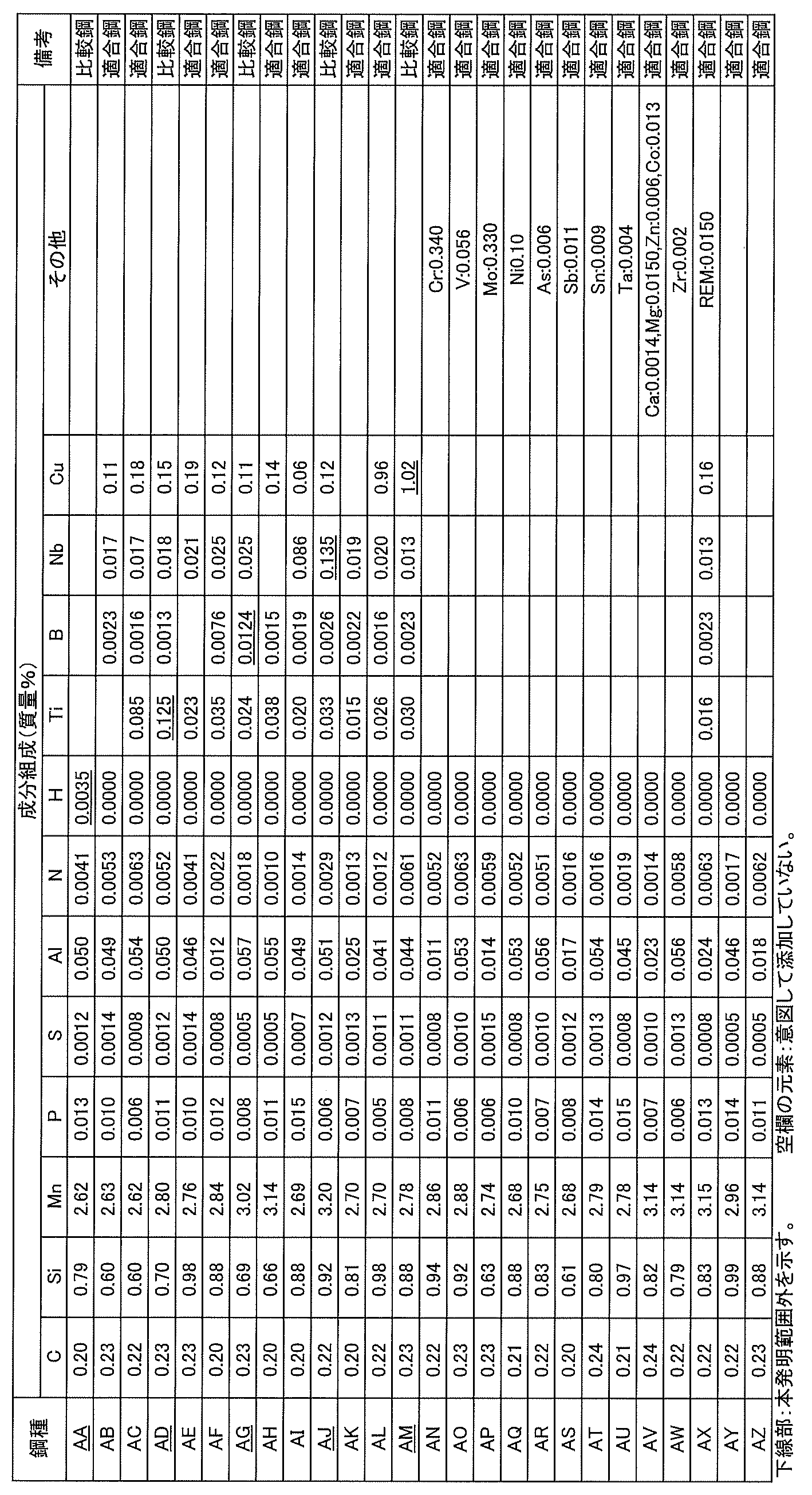
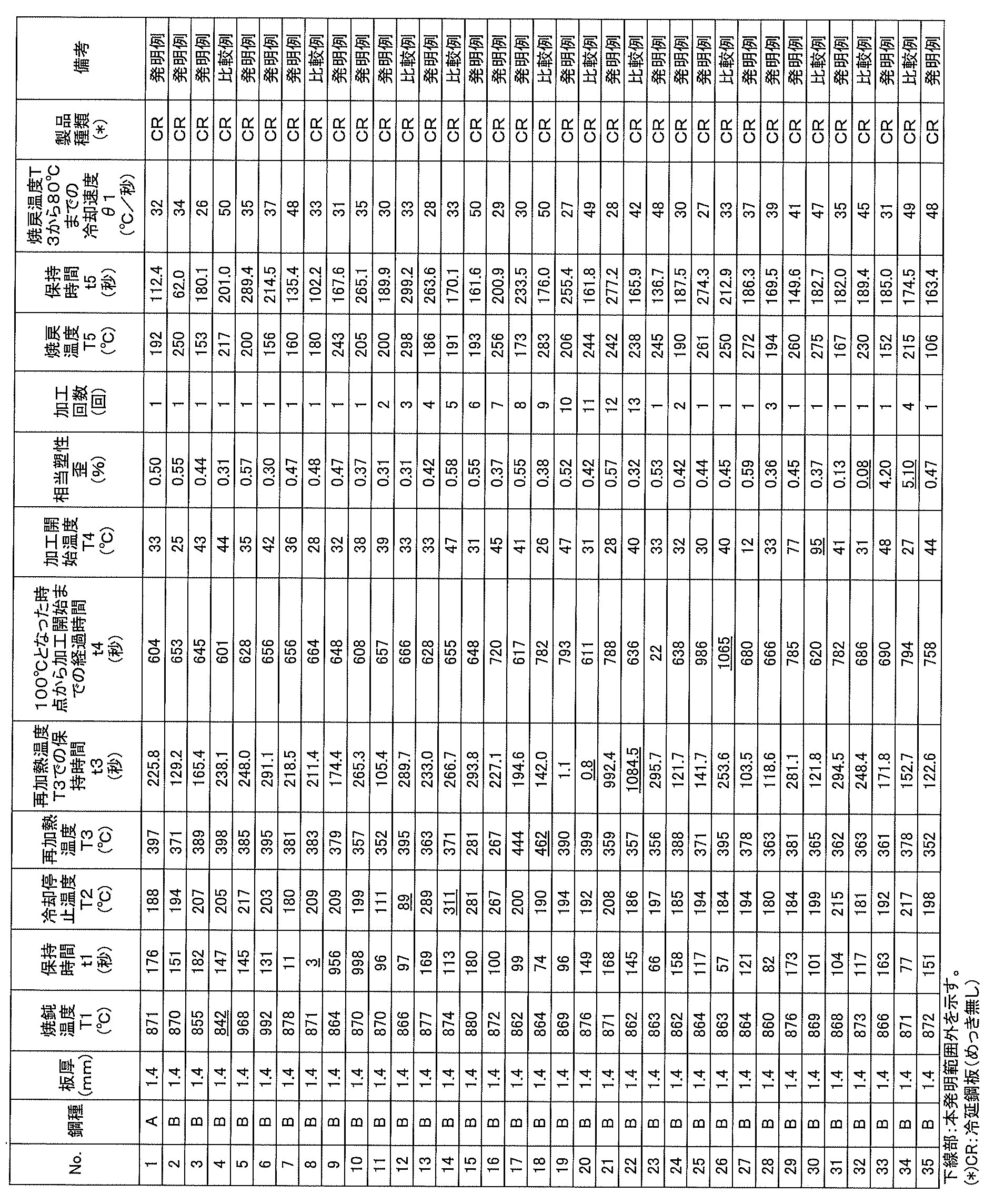
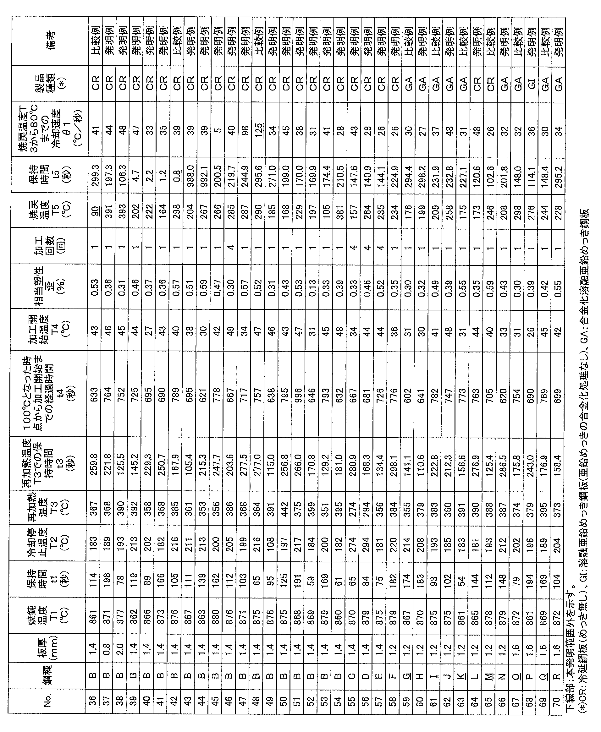

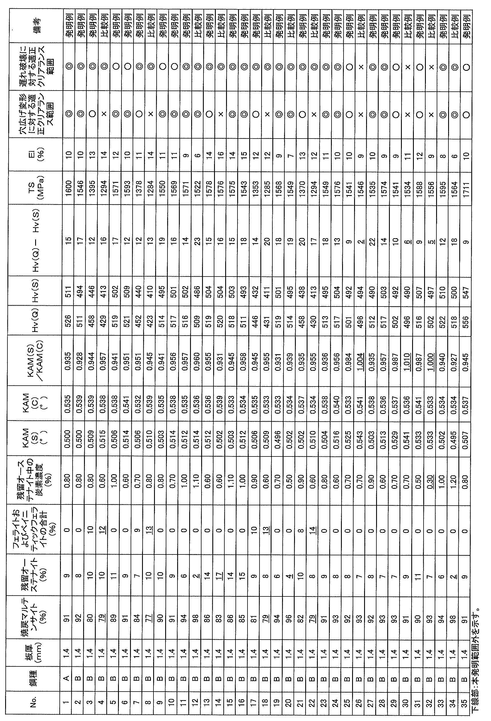

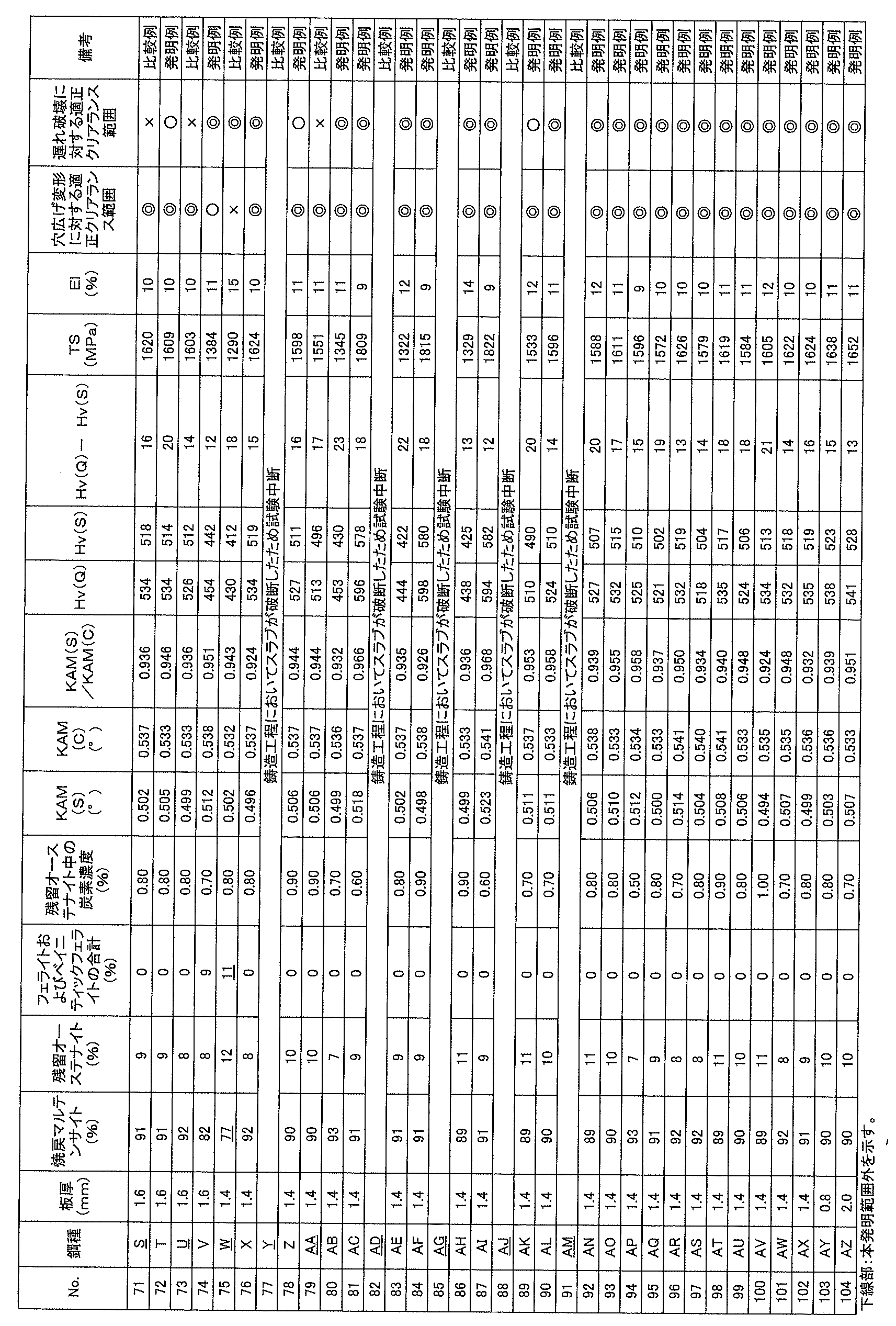
Claims (6)
- 質量%で、
C:0.15%以上、0.45%以下、
Si:0.50%以上、2.00%以下、
Mn:1.50%以上、3.50%以下、
P:0.100%以下、
S:0.0200%以下、
Al:0.010%以上、1.000%以下、
N:0.0100%以下、
H:0.0020%以下を含有し、
残部がFeおよび不可避的不純物からなる成分組成と、
焼戻マルテンサイトが面積分率で80%以上、
残留オーステナイトが体積分率で5%以上15%以下、
フェライトおよびベイニティックフェライトの合計が面積分率で10%以下であり、
残留オーステナイト中の炭素濃度が0.50%以上であり、
以下の(1)および(2)で規定する式を満たす組織を有する高強度鋼板。
KAM(S)/KAM(C) < 1.00 ・・・・・(1)
ここで、KAM(S)は鋼板表層部のKAM(Kernel Average Misorientation)値、KAM(C)は鋼板中心部のKAM値を示す。
Hv(Q)- Hv(S) ≧ 8 ・・・・・(2)
ここで、Hv(Q)は板厚1/4部の硬度、Hv(S)は鋼板表層部の硬度を示す。 - 成分組成として、さらに、質量%で、
Ti:0.100%以下、
B:0.0100%以下、
Nb:0.100%以下、
Cu:1.00%以下、
Cr:1.00%以下、
V:0.100%以下、
Mo:0.500%以下、
Ni:0.50%以下、
Sb:0.200%以下、
Sn:0.200%以下、
As:0.100%以下、
Ta:0.100%以下、
Ca:0.0200%以下、
Mg:0.0200%以下、
Zn:0.020%以下、
Co:0.020%以下、
Zr:0.020%以下、
REM:0.0200%以下のうちから選ばれる1種または2種以上の元素を含有する請求項1に記載の高強度鋼板。 - 鋼板表面にめっき層を有する請求項1または2に記載の高強度鋼板。
- 請求項1または2に記載の高強度鋼板の製造方法であって、
鋼スラブに熱間圧延、酸洗および冷間圧延を施し作製した冷延鋼板を、
温度T1が850℃以上1000℃以下であり、
前記T1での保持時間t1が10秒以上1000秒以下である条件で焼鈍した後、
100℃以上300℃以下の温度T2まで冷却した後、
温度T3がT2以上450℃以下であり、
温度T3での保持時間t3が1.0秒以上1000.0秒以下である条件で再加熱処理を行い、
100℃以下まで冷却し、
100℃となった時点から経過時間t4が1000秒以下のうちに加工を開始し、
前記加工は加工開始温度T4が80℃以下であり、
前記加工は相当塑性歪が0.10%以上5.00%以下である条件で加工を施し、
温度T5が100℃以上400℃以下であり、
前記温度T5での保持時間t5が1.0秒以上1000.0秒以下である条件で焼戻し、
前記温度T5から80℃までの冷却速度θ1が100℃/秒以下の条件で冷却する
高強度鋼板の製造方法。 - 前記焼戻前の加工工程にて2回以上に分けて加工による歪付与を実施し、各加工の前記相当塑性歪の合計が0.10%以上である条件で加工が施される請求項4に記載の高強度鋼板の製造方法。
- 前記焼鈍から加工までの間に、めっき処理を施す請求項4または5に記載の高強度鋼板の製造方法。
Priority Applications (6)
| Application Number | Priority Date | Filing Date | Title |
|---|---|---|---|
| KR1020237042126A KR102905605B1 (ko) | 2021-06-11 | 2022-05-19 | 고강도 강판 및 그의 제조 방법 |
| MX2023014592A MX2023014592A (es) | 2021-06-11 | 2022-05-19 | Chapa de acero de alta resistencia y metodo para fabricar la misma. |
| EP22820020.0A EP4332254B1 (en) | 2021-06-11 | 2022-05-19 | High-strength steel sheet and method for manufacturing the same |
| JP2022551344A JP7215646B1 (ja) | 2021-06-11 | 2022-05-19 | 高強度鋼板およびその製造方法 |
| US18/564,791 US12428700B2 (en) | 2021-06-11 | 2022-05-19 | High strength steel sheet and method for manufacturing the same |
| CN202280039175.6A CN117413083A (zh) | 2021-06-11 | 2022-05-19 | 高强度钢板及其制造方法 |
Applications Claiming Priority (2)
| Application Number | Priority Date | Filing Date | Title |
|---|---|---|---|
| JP2021-098035 | 2021-06-11 | ||
| JP2021098035 | 2021-06-11 |
Publications (1)
| Publication Number | Publication Date |
|---|---|
| WO2022259838A1 true WO2022259838A1 (ja) | 2022-12-15 |
Family
ID=84424862
Family Applications (1)
| Application Number | Title | Priority Date | Filing Date |
|---|---|---|---|
| PCT/JP2022/020893 Ceased WO2022259838A1 (ja) | 2021-06-11 | 2022-05-19 | 高強度鋼板およびその製造方法 |
Country Status (7)
| Country | Link |
|---|---|
| US (1) | US12428700B2 (ja) |
| EP (1) | EP4332254B1 (ja) |
| JP (1) | JP7215646B1 (ja) |
| KR (1) | KR102905605B1 (ja) |
| CN (1) | CN117413083A (ja) |
| MX (1) | MX2023014592A (ja) |
| WO (1) | WO2022259838A1 (ja) |
Cited By (9)
| Publication number | Priority date | Publication date | Assignee | Title |
|---|---|---|---|---|
| WO2024185764A1 (ja) * | 2023-03-06 | 2024-09-12 | Jfeスチール株式会社 | 高強度鋼板およびその製造方法 |
| WO2024185768A1 (ja) * | 2023-03-06 | 2024-09-12 | Jfeスチール株式会社 | 高強度鋼板およびその製造方法 |
| SE2350335A1 (en) * | 2023-03-24 | 2024-09-25 | Voestalpine Stahl Gmbh | A high strength steel strip or sheet, and a method for producing the same |
| WO2024195201A1 (ja) * | 2023-03-23 | 2024-09-26 | Jfeスチール株式会社 | 鋼板および部材、ならびに、それらの製造方法 |
| WO2024195200A1 (ja) * | 2023-03-23 | 2024-09-26 | Jfeスチール株式会社 | 鋼板および部材、ならびに、それらの製造方法 |
| WO2024202227A1 (ja) * | 2023-03-27 | 2024-10-03 | Jfeスチール株式会社 | 鋼板および部材、ならびに、それらの製造方法 |
| WO2025150338A1 (ja) * | 2024-01-09 | 2025-07-17 | Jfeスチール株式会社 | 亜鉛系めっき鋼板及びその製造方法 |
| JPWO2025150337A1 (ja) * | 2024-01-09 | 2025-07-17 | ||
| WO2026063176A1 (ja) * | 2024-09-18 | 2026-03-26 | Jfeスチール株式会社 | 高強度鋼板およびその製造方法 |
Families Citing this family (1)
| Publication number | Priority date | Publication date | Assignee | Title |
|---|---|---|---|---|
| MX2023014591A (es) * | 2021-06-11 | 2023-12-15 | Jfe Steel Corp | Chapa de acero de alta resistencia y metodo para fabricar la misma. |
Citations (9)
| Publication number | Priority date | Publication date | Assignee | Title |
|---|---|---|---|---|
| JP2016509631A (ja) * | 2013-03-28 | 2016-03-31 | 宝山鋼鉄股▲分▼有限公司 | 高性能の低合金耐摩耗鋼板およびその製造方法 |
| JP6112261B2 (ja) | 2015-03-25 | 2017-04-12 | Jfeスチール株式会社 | 冷延鋼板およびその製造方法 |
| JP6354909B2 (ja) | 2015-12-28 | 2018-07-11 | Jfeスチール株式会社 | 高強度鋼板、高強度亜鉛めっき鋼板及びこれらの製造方法 |
| WO2018147400A1 (ja) * | 2017-02-13 | 2018-08-16 | Jfeスチール株式会社 | 高強度鋼板およびその製造方法 |
| JP6525114B1 (ja) | 2017-11-29 | 2019-06-05 | Jfeスチール株式会社 | 高強度亜鉛めっき鋼板およびその製造方法 |
| WO2019212045A1 (ja) * | 2018-05-01 | 2019-11-07 | 日本製鉄株式会社 | 亜鉛系めっき鋼板及びその製造方法 |
| WO2020196060A1 (ja) * | 2019-03-28 | 2020-10-01 | 日本製鉄株式会社 | 高強度鋼板 |
| WO2020262652A1 (ja) * | 2019-06-28 | 2020-12-30 | 日本製鉄株式会社 | 鋼板 |
| WO2020262651A1 (ja) * | 2019-06-28 | 2020-12-30 | 日本製鉄株式会社 | 鋼板 |
Family Cites Families (6)
| Publication number | Priority date | Publication date | Assignee | Title |
|---|---|---|---|---|
| BR112013025015B1 (pt) * | 2011-03-28 | 2018-11-06 | Nippon Steel & Sumitomo Metal Corporation | chapa de aço laminada a frio e método de produção da mesma |
| WO2019122964A1 (en) * | 2017-12-19 | 2019-06-27 | Arcelormittal | Steel sheet having excellent toughness, ductility and strength, and manufacturing method thereof |
| JP6791371B2 (ja) * | 2017-12-26 | 2020-11-25 | Jfeスチール株式会社 | 高強度冷延鋼板及びその製造方法 |
| CN111527223B (zh) * | 2017-12-26 | 2021-09-21 | 杰富意钢铁株式会社 | 高强度冷轧钢板及其制造方法 |
| KR102517187B1 (ko) * | 2018-10-17 | 2023-04-03 | 제이에프이 스틸 가부시키가이샤 | 박강판 및 그의 제조 방법 |
| EP3950975A4 (en) | 2019-03-29 | 2022-12-14 | Nippon Steel Corporation | GALVANISED STEEL |
-
2022
- 2022-05-19 US US18/564,791 patent/US12428700B2/en active Active
- 2022-05-19 CN CN202280039175.6A patent/CN117413083A/zh active Pending
- 2022-05-19 EP EP22820020.0A patent/EP4332254B1/en active Active
- 2022-05-19 KR KR1020237042126A patent/KR102905605B1/ko active Active
- 2022-05-19 WO PCT/JP2022/020893 patent/WO2022259838A1/ja not_active Ceased
- 2022-05-19 MX MX2023014592A patent/MX2023014592A/es unknown
- 2022-05-19 JP JP2022551344A patent/JP7215646B1/ja active Active
Patent Citations (9)
| Publication number | Priority date | Publication date | Assignee | Title |
|---|---|---|---|---|
| JP2016509631A (ja) * | 2013-03-28 | 2016-03-31 | 宝山鋼鉄股▲分▼有限公司 | 高性能の低合金耐摩耗鋼板およびその製造方法 |
| JP6112261B2 (ja) | 2015-03-25 | 2017-04-12 | Jfeスチール株式会社 | 冷延鋼板およびその製造方法 |
| JP6354909B2 (ja) | 2015-12-28 | 2018-07-11 | Jfeスチール株式会社 | 高強度鋼板、高強度亜鉛めっき鋼板及びこれらの製造方法 |
| WO2018147400A1 (ja) * | 2017-02-13 | 2018-08-16 | Jfeスチール株式会社 | 高強度鋼板およびその製造方法 |
| JP6525114B1 (ja) | 2017-11-29 | 2019-06-05 | Jfeスチール株式会社 | 高強度亜鉛めっき鋼板およびその製造方法 |
| WO2019212045A1 (ja) * | 2018-05-01 | 2019-11-07 | 日本製鉄株式会社 | 亜鉛系めっき鋼板及びその製造方法 |
| WO2020196060A1 (ja) * | 2019-03-28 | 2020-10-01 | 日本製鉄株式会社 | 高強度鋼板 |
| WO2020262652A1 (ja) * | 2019-06-28 | 2020-12-30 | 日本製鉄株式会社 | 鋼板 |
| WO2020262651A1 (ja) * | 2019-06-28 | 2020-12-30 | 日本製鉄株式会社 | 鋼板 |
Non-Patent Citations (2)
| Title |
|---|
| See also references of EP4332254A4 |
| YOSHISUKE MISAKATAKESHI MASUISOSEI TO KAKOU, JOURNAL OF JSTP, vol. 17, 1976, pages 988 |
Cited By (22)
| Publication number | Priority date | Publication date | Assignee | Title |
|---|---|---|---|---|
| WO2024185764A1 (ja) * | 2023-03-06 | 2024-09-12 | Jfeスチール株式会社 | 高強度鋼板およびその製造方法 |
| WO2024185768A1 (ja) * | 2023-03-06 | 2024-09-12 | Jfeスチール株式会社 | 高強度鋼板およびその製造方法 |
| JPWO2024185768A1 (ja) * | 2023-03-06 | 2024-09-12 | ||
| JPWO2024185764A1 (ja) * | 2023-03-06 | 2024-09-12 | ||
| JP7666748B2 (ja) | 2023-03-06 | 2025-04-22 | Jfeスチール株式会社 | 高強度鋼板およびその製造方法 |
| JP7666749B2 (ja) | 2023-03-06 | 2025-04-22 | Jfeスチール株式会社 | 高強度鋼板およびその製造方法 |
| JP7597272B1 (ja) * | 2023-03-23 | 2024-12-10 | Jfeスチール株式会社 | 鋼板および部材、ならびに、それらの製造方法 |
| WO2024195200A1 (ja) * | 2023-03-23 | 2024-09-26 | Jfeスチール株式会社 | 鋼板および部材、ならびに、それらの製造方法 |
| JP7597270B1 (ja) * | 2023-03-23 | 2024-12-10 | Jfeスチール株式会社 | 鋼板および部材、ならびに、それらの製造方法 |
| WO2024195201A1 (ja) * | 2023-03-23 | 2024-09-26 | Jfeスチール株式会社 | 鋼板および部材、ならびに、それらの製造方法 |
| SE547321C2 (en) * | 2023-03-24 | 2025-07-01 | Voestalpine Stahl Gmbh | A high strength steel strip or sheet, and a method for producing the same |
| SE2350335A1 (en) * | 2023-03-24 | 2024-09-25 | Voestalpine Stahl Gmbh | A high strength steel strip or sheet, and a method for producing the same |
| JP7597273B1 (ja) * | 2023-03-27 | 2024-12-10 | Jfeスチール株式会社 | 鋼板および部材、ならびに、それらの製造方法 |
| WO2024202227A1 (ja) * | 2023-03-27 | 2024-10-03 | Jfeスチール株式会社 | 鋼板および部材、ならびに、それらの製造方法 |
| WO2025150338A1 (ja) * | 2024-01-09 | 2025-07-17 | Jfeスチール株式会社 | 亜鉛系めっき鋼板及びその製造方法 |
| JPWO2025150338A1 (ja) * | 2024-01-09 | 2025-07-17 | ||
| JPWO2025150337A1 (ja) * | 2024-01-09 | 2025-07-17 | ||
| WO2025150337A1 (ja) * | 2024-01-09 | 2025-07-17 | Jfeスチール株式会社 | 亜鉛系めっき鋼板及びその製造方法 |
| JP7786646B2 (ja) | 2024-01-09 | 2025-12-16 | Jfeスチール株式会社 | 亜鉛系めっき鋼板及びその製造方法 |
| JP7786644B2 (ja) | 2024-01-09 | 2025-12-16 | Jfeスチール株式会社 | 亜鉛系めっき鋼板及びその製造方法 |
| WO2026063176A1 (ja) * | 2024-09-18 | 2026-03-26 | Jfeスチール株式会社 | 高強度鋼板およびその製造方法 |
| JP7845595B1 (ja) * | 2024-09-18 | 2026-04-14 | Jfeスチール株式会社 | 高強度鋼板およびその製造方法 |
Also Published As
| Publication number | Publication date |
|---|---|
| US20240376562A1 (en) | 2024-11-14 |
| MX2023014592A (es) | 2023-12-15 |
| KR102905605B1 (ko) | 2025-12-30 |
| US12428700B2 (en) | 2025-09-30 |
| EP4332254A1 (en) | 2024-03-06 |
| EP4332254A4 (en) | 2024-10-16 |
| CN117413083A (zh) | 2024-01-16 |
| JPWO2022259838A1 (ja) | 2022-12-15 |
| KR20240005884A (ko) | 2024-01-12 |
| JP7215646B1 (ja) | 2023-01-31 |
| EP4332254B1 (en) | 2025-10-08 |
Similar Documents
| Publication | Publication Date | Title |
|---|---|---|
| JP7215646B1 (ja) | 高強度鋼板およびその製造方法 | |
| US20240026479A1 (en) | Hot press-formed member having excellent crack propagation resistance and ductility, and method for producing same | |
| JP6354921B1 (ja) | 鋼板およびその製造方法 | |
| KR101706485B1 (ko) | 고강도 냉연 강판 및 그 제조 방법 | |
| JP2017048412A (ja) | 溶融亜鉛めっき鋼板、合金化溶融亜鉛めっき鋼板、およびそれらの製造方法 | |
| KR20120135521A (ko) | 온간 가공성이 우수한 고강도 강판 및 그 제조 방법 | |
| WO2016031165A1 (ja) | 伸びフランジ性、伸びフランジ性の面内安定性および曲げ性に優れた高強度溶融亜鉛めっき鋼板ならびにその製造方法 | |
| JP2001192768A (ja) | 高張力溶融亜鉛めっき鋼板およびその製造方法 | |
| JP7215647B1 (ja) | 高強度鋼板およびその製造方法 | |
| CN114945690B (zh) | 钢板及其制造方法 | |
| KR20220129615A (ko) | 강판, 부재 및 그들의 제조 방법 | |
| CN117083408A (zh) | 高强度钢板及其制造方法 | |
| KR20230016218A (ko) | 열처리 냉연 강판 및 그 제조 방법 | |
| WO2022190958A1 (ja) | 冷延鋼板及びその製造方法 | |
| JP2013216936A (ja) | 合金化溶融亜鉛めっき熱延鋼板およびその製造方法 | |
| JP2005206920A (ja) | 伸びフランジ性に優れた複合組織型低降伏比高張力溶融亜鉛めっき熱延鋼板及びその製造方法 | |
| WO2023189175A1 (ja) | ホットスタンプ用鋼板及びホットスタンプ成形体 | |
| JP2005206919A (ja) | 延性と伸びフランジ性に優れた複合組織型高張力溶融亜鉛めっき熱延鋼板及びその製造方法 | |
| JP7323094B1 (ja) | 高強度鋼板およびその製造方法 | |
| JP7193044B1 (ja) | 高強度鋼板およびその製造方法、ならびに、部材 | |
| JP7666748B2 (ja) | 高強度鋼板およびその製造方法 | |
| JP7666749B2 (ja) | 高強度鋼板およびその製造方法 | |
| JP7800779B1 (ja) | 高強度鋼板およびその製造方法 | |
| EP4640883A1 (en) | Cold-rolled steel sheet and manufacturing method therefor |
Legal Events
| Date | Code | Title | Description |
|---|---|---|---|
| ENP | Entry into the national phase |
Ref document number: 2022551344 Country of ref document: JP Kind code of ref document: A |
|
| 121 | Ep: the epo has been informed by wipo that ep was designated in this application |
Ref document number: 22820020 Country of ref document: EP Kind code of ref document: A1 |
|
| WWE | Wipo information: entry into national phase |
Ref document number: 202317076301 Country of ref document: IN |
|
| WWE | Wipo information: entry into national phase |
Ref document number: 18564791 Country of ref document: US |
|
| WWE | Wipo information: entry into national phase |
Ref document number: 2022820020 Country of ref document: EP |
|
| WWE | Wipo information: entry into national phase |
Ref document number: 202280039175.6 Country of ref document: CN |
|
| WWE | Wipo information: entry into national phase |
Ref document number: 2301007930 Country of ref document: TH |
|
| ENP | Entry into the national phase |
Ref document number: 20237042126 Country of ref document: KR Kind code of ref document: A |
|
| WWE | Wipo information: entry into national phase |
Ref document number: MX/A/2023/014592 Country of ref document: MX Ref document number: 1020237042126 Country of ref document: KR |
|
| ENP | Entry into the national phase |
Ref document number: 2022820020 Country of ref document: EP Effective date: 20231129 |
|
| NENP | Non-entry into the national phase |
Ref country code: DE |
|
| WWG | Wipo information: grant in national office |
Ref document number: 18564791 Country of ref document: US |
|
| WWG | Wipo information: grant in national office |
Ref document number: 2022820020 Country of ref document: EP |
|
| WWG | Wipo information: grant in national office |
Ref document number: 1020237042126 Country of ref document: KR |