WO2022269701A1 - 吸引器用コントローラ - Google Patents
吸引器用コントローラ Download PDFInfo
- Publication number
- WO2022269701A1 WO2022269701A1 PCT/JP2021/023447 JP2021023447W WO2022269701A1 WO 2022269701 A1 WO2022269701 A1 WO 2022269701A1 JP 2021023447 W JP2021023447 W JP 2021023447W WO 2022269701 A1 WO2022269701 A1 WO 2022269701A1
- Authority
- WO
- WIPO (PCT)
- Prior art keywords
- threshold
- indicator
- power supply
- display
- remaining amount
- Prior art date
- Legal status (The legal status is an assumption and is not a legal conclusion. Google has not performed a legal analysis and makes no representation as to the accuracy of the status listed.)
- Ceased
Links
Images





Classifications
-
- A—HUMAN NECESSITIES
- A24—TOBACCO; CIGARS; CIGARETTES; SIMULATED SMOKING DEVICES; SMOKERS' REQUISITES
- A24F—SMOKERS' REQUISITES; MATCH BOXES; SIMULATED SMOKING DEVICES
- A24F40/00—Electrically operated smoking devices; Component parts thereof; Manufacture thereof; Maintenance or testing thereof; Charging means specially adapted therefor
- A24F40/60—Devices with integrated user interfaces
-
- A—HUMAN NECESSITIES
- A24—TOBACCO; CIGARS; CIGARETTES; SIMULATED SMOKING DEVICES; SMOKERS' REQUISITES
- A24F—SMOKERS' REQUISITES; MATCH BOXES; SIMULATED SMOKING DEVICES
- A24F40/00—Electrically operated smoking devices; Component parts thereof; Manufacture thereof; Maintenance or testing thereof; Charging means specially adapted therefor
- A24F40/40—Constructional details, e.g. connection of cartridges and battery parts
- A24F40/46—Shape or structure of electric heating means
-
- A—HUMAN NECESSITIES
- A24—TOBACCO; CIGARS; CIGARETTES; SIMULATED SMOKING DEVICES; SMOKERS' REQUISITES
- A24F—SMOKERS' REQUISITES; MATCH BOXES; SIMULATED SMOKING DEVICES
- A24F40/00—Electrically operated smoking devices; Component parts thereof; Manufacture thereof; Maintenance or testing thereof; Charging means specially adapted therefor
- A24F40/50—Control or monitoring
-
- A—HUMAN NECESSITIES
- A24—TOBACCO; CIGARS; CIGARETTES; SIMULATED SMOKING DEVICES; SMOKERS' REQUISITES
- A24F—SMOKERS' REQUISITES; MATCH BOXES; SIMULATED SMOKING DEVICES
- A24F40/00—Electrically operated smoking devices; Component parts thereof; Manufacture thereof; Maintenance or testing thereof; Charging means specially adapted therefor
- A24F40/50—Control or monitoring
- A24F40/53—Monitoring, e.g. fault detection
-
- H—ELECTRICITY
- H02—GENERATION; CONVERSION OR DISTRIBUTION OF ELECTRIC POWER
- H02J—ELECTRIC POWER NETWORKS; CIRCUIT ARRANGEMENTS OR SYSTEMS FOR SUPPLYING OR DISTRIBUTING ELECTRIC POWER; SYSTEMS FOR STORING ELECTRIC ENERGY
- H02J7/00—Circuit arrangements for charging or discharging batteries or for supplying loads from batteries
- H02J7/80—Circuit arrangements for charging or discharging batteries or for supplying loads from batteries including monitoring or indicating arrangements
- H02J7/82—Control of state of charge [SOC]
-
- A—HUMAN NECESSITIES
- A24—TOBACCO; CIGARS; CIGARETTES; SIMULATED SMOKING DEVICES; SMOKERS' REQUISITES
- A24F—SMOKERS' REQUISITES; MATCH BOXES; SIMULATED SMOKING DEVICES
- A24F40/00—Electrically operated smoking devices; Component parts thereof; Manufacture thereof; Maintenance or testing thereof; Charging means specially adapted therefor
- A24F40/10—Devices using liquid inhalable precursors
-
- A—HUMAN NECESSITIES
- A24—TOBACCO; CIGARS; CIGARETTES; SIMULATED SMOKING DEVICES; SMOKERS' REQUISITES
- A24F—SMOKERS' REQUISITES; MATCH BOXES; SIMULATED SMOKING DEVICES
- A24F40/00—Electrically operated smoking devices; Component parts thereof; Manufacture thereof; Maintenance or testing thereof; Charging means specially adapted therefor
- A24F40/90—Arrangements or methods specially adapted for charging batteries thereof
-
- H—ELECTRICITY
- H02—GENERATION; CONVERSION OR DISTRIBUTION OF ELECTRIC POWER
- H02J—ELECTRIC POWER NETWORKS; CIRCUIT ARRANGEMENTS OR SYSTEMS FOR SUPPLYING OR DISTRIBUTING ELECTRIC POWER; SYSTEMS FOR STORING ELECTRIC ENERGY
- H02J7/00—Circuit arrangements for charging or discharging batteries or for supplying loads from batteries
- H02J7/70—Circuit arrangements for charging or discharging batteries or for supplying loads from batteries characterised by the mechanical construction
- H02J7/751—Circuit arrangements for charging or discharging batteries or for supplying loads from batteries characterised by the mechanical construction concerning the insertion or the connection of the batteries
Definitions
- the present invention relates to an aspirator controller.
- the number of puff actions (sucking actions) that can be performed per charge can be an important indicator. In order to improve such an index, it is important to reduce the power consumption of the display section and the like of the aerosol generator.
- Patent Document 1 describes that electronic paper (e-ink) was adopted for the display of electronic cigarettes in order to reduce power consumption.
- Patent Document 2 and Patent Document 3 also describe that e-ink can be adopted for the display portion of the aspirator.
- Patent Literatures 1, 2, and 3 do not disclose the timing or conditions for updating the display of the electronic paper, and thus have no technical significance beyond the use of electronic paper as a display device. not to provide.
- One aspect of the present invention provides a suitable control example of a non-volatile display in an aspirator controller.
- One aspect of the present invention relates to an inhaler controller operated by power supplied from a rechargeable power source, the inhaler controller comprising a holding portion holding an atomizer having a heater for heating an aerosol source; a non-volatile display for displaying an indicator relating to the remaining power level of the power supply, changing the indicator when the remaining power level falls below a first threshold during discharging of the power supply, and changing the indicator when the remaining power level becomes less than the first threshold during charging of the power supply. a processor for changing said indicator if it exceeds a different second threshold.
- the processor changes the indicator from a first indicator to a second indicator when the remaining capacity falls below the first threshold during discharging of the power supply, and changes the remaining capacity during charging of the power supply to the second indicator. 2, the index is changed from the second index to the first index.
- the processor changes the second indicator to a third indicator when the remaining capacity falls below a third threshold smaller than the first threshold during discharging of the power supply, and changes the remaining capacity during charging of the power supply. exceeds a fourth threshold which is smaller than the second threshold, the third index is changed to the second index.
- the second threshold is greater than the first threshold.
- the second threshold is less than the first threshold.
- the difference between the second threshold and the first threshold is greater than the change in the remaining amount due to heating of the heater corresponding to at least one puff.
- the non-volatile display selectively displays the first index or the second index as the index regarding the remaining power of the power source, and the first index indicates that the remaining power is sufficient. and the second indicator indicates that the remaining amount is insufficient.
- the difference between the maximum remaining amount and the second threshold is smaller than the difference between the second threshold and the first threshold.
- the processor suppresses discharging of the power supply when the remaining amount falls below a predetermined value, and the difference between the second threshold and the first threshold is equal to the first threshold and the predetermined value. greater than the difference from the value
- the difference between the first threshold and the predetermined value is greater than the difference between the maximum remaining amount and the second threshold.
- the processor is configured to heat the aerosol source according to preset temperature control information, and the heating of the aerosol source according to the temperature control information is in one sequence. Yes, and the difference between the second threshold and the first threshold is greater than the change in the remaining amount due to at least one execution of the sequence.
- an image is displayed on the non-volatile display indicating that it is being charged.
- a charging connector to which power is supplied to charge the power supply is further provided, and the processor changes display of the non-volatile display using power supplied through the charging connector.
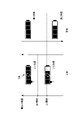
- FIG. 4 is a diagram showing a state transition diagram of an aspirator or a power supply unit and a display example of a display;
- FIG. 4 is a diagram showing a display example of a display;
- FIG. 4 is a diagram showing one example of transition of the remaining battery level indicator displayed on the display;
- FIG. 5 is a diagram showing another example of transition of the remaining battery level indicator displayed on the display;
- FIG. 10 is a diagram showing still another example of transition of the remaining battery level indicator displayed on the display;
- FIG. 4 is a diagram showing an example of the operation of the processor 207 regarding display of the remaining battery level indicator;
- FIG. 4 is a diagram showing an example of the operation of the processor 207 regarding display of the remaining battery level indicator;
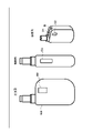
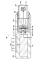
- FIG. 1 shows an exploded perspective view of the aspirator 100
- FIG. 2 shows assembled completed views (front view, side view, perspective view) of the aspirator 100
- FIG. is shown.
- the inhaler 100 produces an aerosol, a flavored aerosol, or an aerosol and a flavoring substance in response to an operation that requests the generation of aerosol, such as an inhalation operation by the user (hereinafter also referred to as an “atomization request”).
- a gas or aerosol containing a flavoring agent or an aerosol containing a flavoring substance may be configured to be provided to the user through the mouthpiece 130 .
- the inhaler 100 may comprise a power supply unit 102 as a controller for the inhaler, an atomizer 104, a capsule holder 105 and a capsule 106.
- the atomizer 104 may be configured to generate a flavored aerosol from a source of aerosol source.
- the aerosol source can be a liquid such as, for example, a polyhydric alcohol such as glycerin or propylene glycol. Alternatively, the aerosol source may contain a medicament.
- the aerosol source can be liquid, solid, or a mixture of liquid and solid. Instead of an aerosol source, a vapor source such as water may be used.
- Atomizer 104 may be provided as a cartridge that is removable from power supply unit 102 .
- the atomizer 104 may be non-removably attached to the power supply unit 102 . In this specification, atomizer 104 is also referred to as cartridge 104 .
- the power supply unit 102 may be understood as a drive unit that drives the atomizer 104, a holder that holds the atomizer 104, a main body that causes the atomizer 104 to function, or the like.
- the power supply unit 102 can have a holding portion 103 that holds the atomizer 104 .
- Retainer 103 may be configured to house all or part of atomizer 104 .
- the holding part 103 may also be configured to hold the capsule-holder 105 .
- capsule-holder 105 may be held by atomizer 104 .
- Capsule holder 105 holds capsule 106 .
- Capsule-holder 105 may function in cooperation with retainer 103 to secure atomizer 104 .
- the holding portion 103 may include a locking mechanism that prevents the capsule holder 105 from falling off from the holding portion 103.
- the locking mechanism may include a second engaging portion that engages a first engaging portion that may be provided on the capsule-holder 105 .
- the capsule holder 105 may be integrated with the atomizer 104 or the power supply unit 102. Furthermore, when the capsule 106 is inserted into the opening of the capsule holder 105 , gas can flow between the atomizer 104 and the capsule 106 .
- Capsule 106 may contain flavor source 131 .
- Flavor source 131 may be, for example, a molded body of tobacco material. Alternatively, the flavor source 131 may be composed of plants other than tobacco (for example, mint, herbs, Chinese medicine, coffee beans, etc.). Flavor sources such as menthol may be added to the flavor source. Flavor source 131 may be added to the aerosol source. The user can suck the flavored aerosol by holding the mouthpiece 130 formed at the tip of the capsule 106 in the mouth.
- the power supply unit 102 may include electrical components 110 .
- Electrical component 110 may include user interface 116 .
- power supply unit 102 may be understood to include electrical components 110 and user interface 116 .
- the user interface 116 can include an action button B as an operating unit that can be operated by the user.
- the action button B can be a button for triggering operations such as starting up the power supply unit 102 and displaying information.
- the user interface 116 can further include a first display D1 as a first notification unit and a second display D2 as a second notification unit.
- the display principle may be different between the first display D1 and the second display D2, and in this case, the power consumption may be different.
- the first display D1 can be an organic light emitting diode (OLED) display and the second display D1 can be an electronic paper (e-ink) display.
- An electronic paper (e-ink) display is a type of non-volatile display.
- An OLED display which may be employed as the first display D1, does not require a backlight device as required in a liquid crystal display, since the organic light emitting diodes emit light themselves.
- An electronic paper display that can be employed as the second display D2 does not require power to keep holding the image. Therefore, electronic paper displays consume less power than OLED displays. However, the electronic paper display does not have a self-luminous function like the OLED display, and the visibility in a dark environment is inferior to that of the OLED display.
- the user interface 116 may further include a third notification section apart from the first display D1 and the second display D2.
- the third notification unit can include the third display D3 and/or the vibration generator V.
- a light emitting diode (LED) display may be employed as the third display D3.
- the LED display can be constructed with 10 or fewer, 20 or fewer, or 30 or fewer LEDs, in one example. In this case, although the amount of information that can be displayed by the LED display is smaller than that of the electronic paper display, the LED display can achieve high brightness and therefore has high visibility.
- the LED display may be a display composed of an LED array.
- the vibration generator V can be configured with a vibration motor for vibrating the housing of the power supply unit 102 . By vibrating the casing with the vibration motor, it is possible to inform the user holding the casing of the state of the power supply unit 102 .
- the power consumption of the first display D1 and the power consumption of the third display are greater than the power consumption of the second display D2, and the power consumption of the first display D1 is equal to the power consumption of the third display D3 or the vibration generator V. greater than
- FIG. 2 shows an arrangement example of the action button B, the first display D1, the second display D2 and the third display D3.
- the first display D1 is arranged on the upper surface of the power supply unit 102
- the second display D2 and the third display D3 are arranged on different side surfaces of the power supply unit 102.
- the positions of the displays D1, D2, and D3 may be replaced with each other, or they may be arranged at positions different from those shown in the drawing.
- a third display D3 (eg, an LED display) is arranged around a window for viewing the remaining amount of aerosol source in the atomizer 104, for example, as shown in the side view in FIG. good too.
- the third display D3 may be arranged around the action button B.
- the position where the action button B is arranged is not limited to the illustrated example, and may be arranged at another position.
- the power supply unit 102 can include a first connection portion 111 and a second connection portion 112 .
- the first connecting portion 111 is electrically connected to the third connecting portion 113 of the atomizer 104
- the second connection portion 112 can be electrically connected to the fourth connection portion 114 of the atomizer 104 .
- the first connection portion 111, the second connection portion 112, the third connection portion 113 and the fourth connection portion 114 can be electrical contacts or connectors.
- Power supply unit 102 may supply power to atomizer 104 through first connection 111 and second connection 112 .
- the atomizer 104 can include a third connection 113 and a fourth connection 114 .
- the atomizer 104 also includes a heater 127 for generating a flavored aerosol from an aerosol source, a container 125 for holding the aerosol source, and a heating area for heating the aerosol source held by the container 125 by the heater 127 . and a transport portion 126 that transports to and holds in the heating area. At least a portion of the heated region may be located in a channel 128 provided within the atomizer 104 .
- First connection portion 111 , third connection portion 113 , heater 127 , fourth connection portion 114 , and second connection portion 112 form a current path through which current flows through heater 127 .
- the transport portion 126 may be made of, for example, a fibrous material such as glass fiber, a porous material such as ceramic, or a combination thereof. Note that such a transport 126 may also be called a wick.
- the means for transporting the aerosol source in the container 125 to the heating region is not limited to the wick, and may be realized by a spray device such as a spray or a transport means such as a pump.
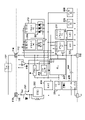
- FIG. 4 shows a configuration example of the electrical component 110.
- Electrical component 110 may comprise a power source 205 and a charging circuit 206 .
- the power source 205 can be a rechargeable battery (secondary battery) such as a lithium ion secondary battery.
- the power supply 205 may consist of an electric double layer capacitor such as a lithium ion capacitor.
- the power supply 205 can be charged using power supplied from the V bus port, for example.
- a power supply device (external power source) (not shown) can be connected to the V bus port via a cable.
- the V bus ports, cables, and power supplies may be configured to comply with Universal Serial Bus (USB) Type-A, Type-B, Type-C, etc. standards, for example.
- USB Universal Serial Bus
- a power source can supply power to the power supply 205 via the cable and V bus port.
- the power supply device can be a personal computer (PC), a charger for a portable battery, or the like.
- PC personal computer
- the power supply unit 102 and the charger can communicate with each other and then charge the power supply 205 from the charger.
- the connection between the power supply unit 102 and the power supply device is not limited to the USB interface, and various other communication methods capable of data communication and power supply may be applied.
- the charging circuit 206 can supply charging current from the charging terminal BAT to the power supply 205 using power supplied from the power supply device to the input terminal IN, thereby charging the power supply 205 . Also, the charging circuit 206 can output power or voltage from the voltage output terminal OUT using the power supplied from the power supply device. Therefore, power or voltage can be supplied from the charging circuit 206 to the voltage converters 202 , 203 , 204 even while the charging circuit 206 is charging the power source 205 . The charging circuit 206 can output power or voltage from the voltage output terminal OUT using the power of the power supply 205 supplied from the charging terminal BAT from the power supply 205 when a power supply device is not connected to the Vbus port. Therefore, power or voltage can be supplied from the charging circuit 206 to the voltage converters 202 , 203 , 204 even when the charging circuit 206 is not charging the power source 205 .
- the electrical component 110 may comprise one or more voltage converters. If electrical component 110 comprises a plurality of voltage converters, at least two of them may generate voltages that are different from each other or equal to each other. In the configuration example shown in FIG. 4 , electrical component 110 comprises voltage converters 202 , 203 , 204 . The electrical component 110 may not have a voltage converter. In this case, the voltage output by the power supply 205 is supplied to the plurality of elements forming the electrical component 110 with a slight voltage drop due to wiring resistance. can be In the configuration example shown in FIG. 4, the voltage converters 202 and 203 are configured by switching regulators such as DC/DC converters, but at least one of them may be configured by an LDO (Low Drop Out).
- LDO Low Drop Out
- the voltage converter 204 may be configured by other types of circuits.
- the voltage converter 204 is configured with an LDO (Low Drop Out), but it may be configured with a switching regulator such as a DC/DC converter, or with another method. may be configured by a circuit of
- the electrical component 110 can include a processor 207 that operates according to preinstalled software (program).
- Processor 207 may be configured to control the elements that make up electrical component 110 .
- the processor 207 can be composed of, for example, an MCU (Micro Controller Unit). Processor 207 may be replaced by other devices such as ASICs.
- the processor 207 may be supplied with voltage (power) by a voltage converter 204 .
- Processor 207 may be configured to control drivers 211 , 212 , 213 , 214 , which are elements that make up electrical component 110 .
- Drivers 211, 212, 213 and 214 drive displays D1, D2 and D3 and vibration motor V, respectively. Therefore, processor 207 may be understood as a processor that drives or controls displays D1, D2, D3 and vibration motor V.
- a voltage (power) can be supplied to the drivers 211 , 212 , 213 , 214 by a voltage converter 204 .
- Voltage converter 204 may supply voltage (power) to action button B as well.
- Action button B may provide an active level (eg, high level) signal to processor 207 when turned from an OFF state to an ON state by a user.
- a voltage (power) may be supplied by a voltage converter 203 to the first display D1, which may be an OLED.
- the displays D2 and D3 and the vibration motor V are supplied with voltage (power) from drivers 212, 213 and 214, respectively.
- at least one of the displays D2, D3 and the vibration motor V may be supplied with voltage (power) from any of the voltage converters 202, 203, 204.
- the power supply unit 102 may include a puff sensor 209 that detects a user's suction action, that is, a puff, and the voltage converter 204 can also supply voltage (power) to the puff sensor 209 .
- the puff sensor 209 detects puffs by, for example, detecting at least one of pressure, sound, and temperature (for example, the temperature of the air flowing into the flow path 128 of the atomizer 104 through the aforementioned openings, the temperature of the heater 127). I can.
- the electrical component 110 can include a switch 201 for controlling energization (supply of power) to the heater 127 that is the load of the atomizer 104 .
- the switch 201 can be, for example, a MOSFET with a body diode, but may also consist of other switching elements.
- Voltage converter 202 may supply voltage (power) to heater 127 via switch 201 .
- a shunt resistor R shunt may be placed in the closed circuit or current path comprising switch 201 and heater 127 .
- Electrical component 110 may include measurement circuitry 210 for measuring the temperature of heater 127 .
- the heater 127 can have a positive or negative temperature coefficient characteristic in which the resistance value RHTR changes according to its own temperature, and the resistance value RHTR of the heater 127 has a strong correlation with the temperature of the heater 127. sell.
- the measurement circuit 210 is a circuit for measuring the resistance value RHTR of the heater 127, and can be configured to measure the voltage across the heater 127 by, for example, an operational amplifier.
- the output of measurement circuit 210 may be provided to processor 207 , which may calculate a resistance value RHTR based on the output of measurement circuit 210 and the value of the current flowing through heater 127 .
- the current value can be obtained, for example, using a sensing circuit that senses the voltage across the shunt resistor Rshunt.
- the detection circuit may be, for example, a circuit that detects the potential difference across the shunt resistor Rshunt, and may be provided in the processor 207 as an AD converter, for example.
- Processor 207 may control switch 201 to feedback control, eg, PID control, the temperature of heater 127 based on the temperature of heater 127 measured using measurement circuit 210 .
- the electrical component 110 may include a first sensor 221 that detects the presence or absence of the cartridge 104 and a second sensor 222 that detects the presence or absence of the capsule 106.
- the outputs of first sensor 221 and second sensor 222 may be provided to processor 207 .
- a voltage (power) can be supplied to the first sensor 221 and the second sensor 222 by a voltage converter 204 .
- the first sensor 221 and the second sensor 222 can be, for example, photointerrupters, proximity sensors, RFID systems or switches.
- a switch that detects the presence or absence of cartridge 104 can be turned on (or off) by inserting cartridge 104 into holding portion 103 and turned off (or on) by removing atomizer 104 from holding portion 103 .
- a switch that senses the presence or absence of capsule 106 may be turned on (or off) by insertion of capsule 106 into holder 103 and turned off (or on) by removal of capsule 106 from holder 103 .
- a state transition of the power supply unit 102 or the aspirator 100 in the embodiment and a display example of the second display D2 in each state will be described with reference to the state transition diagram of FIG.
- Power supply unit 102 may have four modes of operation: sleep mode, active mode, aerosol generation mode, and charge mode.
- the first display D1 may also be controlled to display the same as the second display D2.
- the first display D1 and the third display D3 may be controlled to display a simplified version of the display content of the second display D2.
- the first display D1 and the third display D3 may display information to supplement the information displayed by the second display D1.
- the sleep mode is a state in which the power supply unit 102 suspends its main operations.
- the heater 127 of the atomizer or cartridge 104 is not powered for heating the aerosol source.
- the power consumed by power supply unit 102 may be minimized.
- Sleep mode may also be referred to as power saving mode or standby mode.
- the power supply unit 102 is locked from providing aerosols and the user cannot inhale aerosols.
- the predetermined operation may be, for example, an operation of repeatedly pressing the action button B a predetermined number of times (eg, three times), an operation of long-pressing the action button B for a specified time (eg, three seconds) or longer, or the like. Also, if a predetermined time elapses without a predetermined operation in the active mode, the power supply unit 102 or the aspirator 100 can return to sleep mode.
- the power supply unit 102 shifts to the aerosol generation mode to generate aerosol.
- the power unit 102 may return to active mode when the aspiration ends or when the aspiration time reaches a defined upper time limit.
- the active mode and the aerosol generation mode may be understood as a first mode in which discharge from the power source 205 to the heater 127 can be controlled, and the sleep mode as a second mode that consumes less power than the first mode.
- power supply unit 102 may transition from active mode to aerosol generation mode. In this case, the power supply unit 102 may return to active mode upon detection of a predetermined number of inhalations or elapse of a predetermined time period in the aerosol generation mode.
- a fully charged state means that the SOC (State Of Charge) or the state of charge is 100% or a predetermined value close thereto (for example, 98%, 95% or 90%) or more.
- the power supply unit 102 or the aspirator 100 may have a feature that allows the user to set criteria for what is considered fully charged.
- FIG. 5 shows a display example of the second display D2 in the active mode.
- the remaining amount of flavor source 131 in capsule 106 (hereinafter referred to as “capsule remaining amount”) and the remaining amount of aerosol source in cartridge 104 (hereinafter referred to as “cartridge remaining amount”) are displayed on second display D2.
- an indicator indicating the remaining amount of power that can be discharged by the power supply 205 that is, the remaining amount of the power supply 205 (hereinafter referred to as “remaining battery level”).
- the capsule remaining amount is displayed in a 6-level bar graph format
- the cartridge remaining amount is displayed in a 6-level bar graph format
- the battery remaining amount is displayed in a 5-level bar graph format.
- the remaining amount of the power supply 205 or the remaining battery amount can be evaluated, for example, by SOC (State Of Charge) or charging rate.
- FIG. 5 shows a display example of the second display D2 in the charging mode.
- Capsule level, cartridge level and battery level can also be displayed in charging mode.
- a charging mark indicating that the battery is being charged may be additionally displayed in the area where the remaining battery level is displayed.
- c in FIG. 5 shows a display example of the second display D2 in the aerosol generation mode. Due to the generation of aerosol, the capsule remaining amount, cartridge remaining amount, and battery remaining amount tend to decrease, so as shown in the left part of c in FIG. getting shorter. The right part of c in FIG. 5 indicates that the capsule remaining amount is low and the battery remaining amount is low.
- the second display D2 shows the factors that are consumed to generate the flavored aerosol, such as at least one, at least two, or at least two of the capsule remaining amount, the cartridge remaining amount and the battery remaining amount. It can be controlled by processor 207 to include an indication of all.
- the display modes shown in a to c in FIG. 5 are merely examples, and the display modes of the capsule remaining amount, cartridge remaining amount, and battery remaining amount may be other modes.
- icons such as a1, b1, and c1 in FIG. 6 may indicate only the presence or absence of the remaining amount of each of the plurality of elements.
- the display mode of the second display D2 includes a display specifying which of two states regarding at least one of the plurality of elements. sell. The two states can be a first state indicating sufficient ability to generate a flavored aerosol and a second state indicating an insufficient ability to generate a flavored aerosol.
- the icon without the "! mark indicates the first state
- the icon with the "! mark indicates the second state.
- A1 in FIG. 6 indicates that the capsule remaining amount and cartridge remaining amount are in the first state, and the battery remaining amount is in the second state.
- b1 in FIG. 6 indicates that the capsule remaining amount, cartridge remaining amount, and battery remaining amount are in the first state.
- c1 indicates that the cartridge remaining amount is in the first state, and the capsule remaining amount and battery remaining amount are in the second state.
- the display mode of the second display D2 may indicate each remaining amount by a numerical value.
- FIG. 7 shows an example of transition of the indicator indicating the remaining battery level (hereinafter referred to as the remaining battery level indicator) displayed on the second display D2.
- the remaining battery level indicator indicating the remaining battery level
- a charge mark CM which is an image indicating that the power source 205 is being charged, may be displayed in the charge state.
- the processor 207 changes the battery level indicator when the battery level is below the first threshold when the power supply 205 is discharged, and when the battery level is below the first threshold when the power supply 205 is charged.
- the battery level indicator may be changed when a different second threshold is exceeded.
- the processor 207 changes the battery level indicator from the first indicator to the second indicator when the battery level drops below the first threshold in discharging the power supply 205, and changes the battery level indicator to the second indicator in charging the power supply 205. can be changed from the second index to the first index.
- FIG. 8 shows another example of transition of the remaining battery level indicator displayed on the second display D2.
- the processor 207 changes the second indicator to the third indicator when the remaining battery capacity falls below a third threshold that is less than the first threshold in discharging the power supply 205, and changes the battery level in charging the power supply 205.
- the third indicator may be changed to the second indicator when the remaining amount exceeds a fourth threshold which is less than the second threshold.
- the remaining battery level is displayed in five levels, and the remaining battery level indicator has thresholds other than those listed here.
- the remaining charge indicator can include a first indicator (fully charged), a second indicator, a third indicator, a fourth indicator, and a fifth indicator (no remaining capacity).
- the transition between the first index and the second index follows the first threshold (when discharging) and the second threshold (when charging), and the transition between the second index and the third index follows the third threshold (when discharging).
- the fourth threshold (when charging) the transition between the third and fourth indicators follows the fifth threshold (when discharging) and the sixth threshold (when charging), between the fourth and fifth indicators transition may follow the seventh threshold (during discharging) and the eighth threshold (during charging).
- the first and second thresholds may be different, the third and fourth thresholds may be different, the fifth and sixth thresholds may be different, and the seventh and eighth thresholds may be different.
- the threshold which is the determination criterion for changing the remaining battery level indicator during discharging of the power source 205
- the threshold which is the determination criterion for changing the remaining battery level indicator during charging of the power source 205
- the second threshold is greater than the first threshold.
- the fourth threshold is greater than the third threshold.
- the threshold (2i-th threshold (i is a natural number)) during charging may be smaller than the corresponding threshold ((2i-1)th threshold) during discharging.
- the threshold during discharging may be higher than the corresponding threshold during charging.
- the second threshold is smaller than the first threshold and the fourth threshold is smaller than the third threshold.
- the difference between the second threshold and the first threshold is, for example, greater than the change in the remaining battery level due to heating by the heater 127 corresponding to at least one, at least three, at least five, or at least ten puffs.
- the difference between the threshold (2ith threshold (i is a natural number)) during charging and the corresponding threshold ((2i-1)th threshold) during discharging is, for example, at least once, at least three times, or at least five times. , or greater than the change in remaining battery capacity due to heating of heater 127 corresponding to at least 10 puffs.
- inhaler 100, electrical component 110 or processor 207 may control heating of heater 127 to heat the aerosol source according to preset temperature control information.
- a sequence can be defined from the start to the end of heating the aerosol source according to the temperature control information.
- the difference between the second threshold and the first threshold is, for example, greater than the change in remaining battery power due to execution of the sequence at least once, at least three times, at least five times, or at least ten times.
- the difference between the threshold (2ith threshold (i is a natural number)) during charging and the corresponding threshold ((2i-1)th threshold) during discharging is, for example, at least once, at least three times, or at least five times.
- the temperature control information can be, for example, information for controlling temporal changes in the temperature of the heater 127 or power supplied to the heater 127 .
- the temperature control information may be called a temperature profile.
- a period during which the temperature of the heater 127 is controlled based on the temperature control information can include, for example, at least one or at least two temperature raising periods and at least one temperature lowering period. During the temperature increasing period and the temperature decreasing period, the temperature of the heater 127 can be controlled by feedback control or feedforward control.
- Fig. 9 shows still another example of the transition of the remaining battery level indicator displayed on the second display D2.
- the second display D2 alternatively displays the first indicator or the second indicator as the remaining battery level indicator. That is, in the example of FIG. 9, the remaining battery level indicator displayed on the second display D2 has only two types, the first indicator and the second indicator. A first indicator may indicate that the remaining battery power is sufficient, and a second indicator may indicate that the remaining battery power is insufficient.
- the difference (A) between the maximum remaining battery level and the second threshold is smaller than the difference (B) between the second threshold and the first threshold.
- the processor 207 is operable to inhibit discharge of the power source 205 when the remaining battery power is below a predetermined value, and the difference (B) between the second threshold and the first threshold is equal to the first threshold and the predetermined value. It may be greater than the difference (C) from the value.
- the difference (C) between the first threshold and the predetermined value may be larger than the difference (A) between the maximum remaining battery level and the second threshold.
- the power supply unit 102 may include a charging connector, such as the aforementioned V bus port, through which power is supplied to charge the power supply 205, and the processor 207 utilizes the power supplied through the charging connector.
- a charging connector such as the aforementioned V bus port
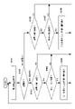
- FIG. 10 shows an example of the operation of the processor 207 regarding display of the remaining battery level indicator.
- the operations illustrated in FIG. 10 may be applied to the display transition between the first index and the second index in the examples illustrated in FIGS.
- the processor 207 acquires the remaining battery level.
- the processor 207 can obtain the remaining battery level by obtaining the output voltage of the power supply 205, for example.
- power supply unit 102 includes a management circuit that manages power supply 205
- processor 207 may obtain based on the output from the management circuit.
- the processor 207 determines whether the current state is the discharge state in which the power source 205 is discharged or the charge state in which the power source 205 is charged.
- the processor 207 can determine that it is in the charging state if the current mode is the charging mode, and can determine that it is in the discharging state if it is in any other mode. If it is in the discharging state, the process proceeds to step S103, and if it is in the charging state, the process proceeds to step S106.
- step S103 the processor 207 determines whether or not the remaining battery level is below the first threshold. If the remaining battery level is below the first threshold, the process proceeds to step S104. is returned to step S101. In step S104, the processor 207 determines whether or not the current remaining battery level indicator displayed by the second display D2 is the first indicator, and if the displayed remaining battery level indicator is the first indicator, step S105. , the first index is changed to the second index, otherwise the process proceeds to step S101 (maintains the first index).
- step S106 the processor 207 determines whether or not the remaining battery level exceeds the second threshold. If the remaining battery level exceeds the second threshold, the process proceeds to step S107. , otherwise the process returns to step S101.
- step S107 the processor 207 determines whether the current battery level indicator displayed on the second display D2 is the second indicator, and if the battery level indicator is the second indicator, step S108. , the second index is changed to the first index, otherwise the process proceeds to step S101 (maintains the second index).
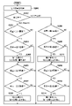
- FIG. 11 shows another example of the operation of the processor 207 regarding the display of the remaining battery level indicator.
- the operation shown in FIG. 11 is applied to the display transition between the first index and the second index and the display transition between the second index and the third index in the example shown in FIG. sell.
- the processor 207 acquires the remaining battery level.
- the processor 207 can obtain the remaining battery level by obtaining the output voltage of the power supply 205, for example.
- power supply unit 102 includes a management circuit that manages power supply 205
- processor 207 may obtain based on the output from the management circuit.
- the processor 207 determines whether the current state is a discharging state in which the power source 205 is being discharged or a charging state in which the power source 205 is being charged.
- the processor 207 can determine that it is in the charging state if the current mode is the charging mode, and can determine that it is in the discharging state if it is in any other mode. If it is in the discharging state, the process proceeds to step S203, and if it is in the charging state, the process proceeds to step S209.
- step S203 the processor 207 determines whether the remaining battery level is below the first threshold. If the remaining battery level is below the first threshold, the process proceeds to step 204; is returned to step S201. In step S204, the processor 207 determines whether the current battery level indicator displayed by the second display D2 is the first indicator, and if the battery level indicator is the first indicator, step S205 , the first index is changed to the second index, otherwise the process proceeds to step S206 (maintains the first index).
- step S206 the processor 207 determines whether or not the remaining battery level is below the third threshold. If the remaining battery level is below the third threshold, the process proceeds to step S207; is returned to step S201. In step S207, the processor 207 determines whether the current display of the remaining battery level indicator on the second display D2 is the second indicator, and if the display of the remaining battery level indicator is the second indicator, step S208. changes the second index to the third index, otherwise the process returns to step S201 (maintains the second index).
- step S209 the processor 207 determines whether or not the remaining battery level exceeds the fourth threshold. , otherwise the process returns to step S201.
- step S210 the processor 207 determines whether the current remaining battery level indicator displayed by the second display D2 is the third indicator, and if the remaining battery level indicator is the third indicator, step S211. , the third index is changed to the second index, otherwise the process proceeds to step S212 (maintains the third index).
- step S212 the processor 207 determines whether or not the remaining battery level exceeds the second threshold. If the remaining battery level exceeds the second threshold, the process proceeds to step 213; is returned to step S201. In step S213, the processor 207 determines whether the current battery level indicator displayed on the second display D2 is the second indicator, and if the battery level indicator is the second indicator, step S214. changes the second index to the first index, otherwise the process returns to step S201 (maintains the first index).
- the remaining battery indicator is displayed on the second display D2, but the remaining battery indicator is displayed using other displays such as at least one of the first display D1 and the third display D3.
- the battery level indicator may be displayed using multiple displays D1, D2, D3.
- at least one of the plurality of displays D1, D2, D3 is used to display one indicator (eg, the first indicator) of the remaining battery level indicators, and at least one other of the plurality of displays D1, D2, D3 is displayed. may be used to display another indicator (eg, the second indicator) of the remaining battery level indicator.
Landscapes
- Engineering & Computer Science (AREA)
- Human Computer Interaction (AREA)
- Power Engineering (AREA)
- Charge And Discharge Circuits For Batteries Or The Like (AREA)
Abstract
Description
Claims (13)
- 充電可能な電源から供給される電力によって動作する吸引器用コントローラであって、
エアロゾル源を加熱するヒータを有する霧化器を保持する保持部と、
前記電源の残量に関する指標を表示する不揮発性ディスプレイと、
前記電源の放電において前記残量が第1閾値を下回ったら前記指標を変更し、前記電源の充電において前記残量が前記第1閾値とは異なる第2閾値を上回ったら前記指標を変更するプロセッサと、
を備えることを特徴とする吸引器用コントローラ。 - 前記プロセッサは、前記電源の放電において前記残量が前記第1閾値を下回ったら前記指標を第1指標から第2指標に変更し、前記電源の充電において前記残量が前記第2閾値を上回ったら前記指標を前記第2指標から前記第1指標に変更する、
ことを特徴とする請求項1に記載の吸引器用コントローラ。 - 前記プロセッサは、前記電源の放電において前記残量が前記第1閾値より小さい第3閾値を下回ったら前記第2指標を第3指標に変更し、前記電源の充電において前記残量が前記第2閾値より小さい第4閾値を上回ったら前記第3指標を前記第2指標に変更する、
ことを特徴とする請求項2に記載の吸引器用コントローラ。 - 前記第2閾値は、前記第1閾値より大きい、
ことを特徴とする請求項1乃至3のいずれか1項に記載の吸引器用コントローラ。 - 前記第2閾値は、前記第1閾値より小さい、
ことを特徴とする請求項1乃至3のいずれか1項に記載の吸引器用コントローラ。 - 前記第2閾値と前記第1閾値との差は、少なくとも1回のパフに対応する前記ヒータの加熱による前記残量の変化より大きい、
ことを特徴とする請求項1乃至3のいずれか1項に記載の吸引器用コントローラ。 - 前記プロセッサは、予め設定された温度制御情報に従って前記エアロゾル源を加熱するように構成され、前記温度制御情報に従った前記エアロゾル源の加熱の開始から終了までが1つのシーケンスであり、
前記第2閾値と前記第1閾値との差は、少なくとも1回の前記シーケンスの実行による前記残量の変化より大きい、
ことを特徴とする請求項1乃至3のいずれか1項に記載の吸引器用コントローラ。 - 前記不揮発性ディスプレイは、前記電源の残量に関する前記指標として、前記第1指標または前記第2指標を択一的に表示し、
前記第1指標は、前記残量が十分であることを示し、前記第2指標は、前記残量が不十分であることを示す、
ことを特徴とする請求項2に記載の吸引器用コントローラ。 - 前記残量の最大値と前記第2閾値との差は、前記第2閾値と前記第1閾値との差より小さい、
ことを特徴とする請求項8に記載の吸引器用コントローラ。 - 前記プロセッサは、前記残量が所定値を下回った場合に、前記電源の放電を抑制し、
前記第2閾値と前記第1閾値との差は、前記第1閾値と前記所定値との差より大きい、
ことを特徴とする請求項9に記載の吸引器用コントローラ。 - 前記第1閾値と前記所定値との差は、前記残量の最大値と前記第2閾値との差より大きい、
ことを特徴とする請求項10に記載の吸引器用コントローラ。 - 前記電源が充電されている状態では、充電中であることを示す画像が前記不揮発性ディスプレイに表示される、
ことを特徴とする請求項1乃至11のいずれか1項に記載の吸引器用コントローラ。 - 前記電源を充電するための電力が供給される充電コネクタを更に備え、
前記プロセッサは、前記充電コネクタを介して供給される電力を利用して前記不揮発性ディスプレイの表示を変更する、
ことを特徴とする請求項1乃至12のいずれか1項に記載の吸引器用コントローラ。
Priority Applications (6)
| Application Number | Priority Date | Filing Date | Title |
|---|---|---|---|
| PCT/JP2021/023447 WO2022269701A1 (ja) | 2021-06-21 | 2021-06-21 | 吸引器用コントローラ |
| EP21946991.3A EP4360482A4 (en) | 2021-06-21 | 2021-06-21 | CONTROL FOR SUCTION DEVICE |
| CN202180099348.9A CN117500395A (zh) | 2021-06-21 | 2021-06-21 | 吸入器用控制器 |
| KR1020247000959A KR102989821B1 (ko) | 2021-06-21 | 2021-06-21 | 흡인기용 컨트롤러 |
| JP2023529228A JP7615322B2 (ja) | 2021-06-21 | 2021-06-21 | 吸引器用コントローラ |
| US18/530,277 US20240099394A1 (en) | 2021-06-21 | 2023-12-06 | Controller for inhalation apparatus |
Applications Claiming Priority (1)
| Application Number | Priority Date | Filing Date | Title |
|---|---|---|---|
| PCT/JP2021/023447 WO2022269701A1 (ja) | 2021-06-21 | 2021-06-21 | 吸引器用コントローラ |
Related Child Applications (1)
| Application Number | Title | Priority Date | Filing Date |
|---|---|---|---|
| US18/530,277 Continuation US20240099394A1 (en) | 2021-06-21 | 2023-12-06 | Controller for inhalation apparatus |
Publications (1)
| Publication Number | Publication Date |
|---|---|
| WO2022269701A1 true WO2022269701A1 (ja) | 2022-12-29 |
Family
ID=84545280
Family Applications (1)
| Application Number | Title | Priority Date | Filing Date |
|---|---|---|---|
| PCT/JP2021/023447 Ceased WO2022269701A1 (ja) | 2021-06-21 | 2021-06-21 | 吸引器用コントローラ |
Country Status (6)
| Country | Link |
|---|---|
| US (1) | US20240099394A1 (ja) |
| EP (1) | EP4360482A4 (ja) |
| JP (1) | JP7615322B2 (ja) |
| KR (1) | KR102989821B1 (ja) |
| CN (1) | CN117500395A (ja) |
| WO (1) | WO2022269701A1 (ja) |
Cited By (3)
| Publication number | Priority date | Publication date | Assignee | Title |
|---|---|---|---|---|
| WO2025125808A1 (en) * | 2023-12-16 | 2025-06-19 | Nicoventures Trading Limited | Battery indication method for aerosol provision system, and aerosol provision system |
| US12438383B2 (en) | 2022-09-19 | 2025-10-07 | Altria Client Services Llc | Charging systems for aerosol-generating devices |
| US12520880B2 (en) | 2021-01-18 | 2026-01-13 | Altria Client Services Llc | Heat-not-burn (HNB) aerosol-generating devices including energy based heater control, and methods of controlling a heater |
Families Citing this family (2)
| Publication number | Priority date | Publication date | Assignee | Title |
|---|---|---|---|---|
| USD1055967S1 (en) * | 2021-04-16 | 2024-12-31 | Koninklijke Philips N.V. | Display screen or portion thereof with animated graphical user interface |
| WO2026008206A1 (en) * | 2024-07-01 | 2026-01-08 | Jt International Sa | An aerosol generation device, and a method of controlling an aerosol generation device during a battery unit replacement procedure |
Citations (5)
| Publication number | Priority date | Publication date | Assignee | Title |
|---|---|---|---|---|
| JP2011035966A (ja) * | 2009-07-30 | 2011-02-17 | Canon Inc | 電子機器システム |
| CN203505584U (zh) | 2013-08-15 | 2014-04-02 | 深圳市万机创意电子科技有限公司 | 一种E-Ink电子纸显示的电子烟 |
| US8851068B2 (en) | 2009-04-21 | 2014-10-07 | Aj Marketing Llc | Personal inhalation devices |
| US20170150756A1 (en) * | 2015-11-30 | 2017-06-01 | National Concessions Group Inc. | Dual-activation for vaporizer devices |
| JP2019510489A (ja) * | 2016-03-04 | 2019-04-18 | アール・エイ・アイ・ストラテジック・ホールディングス・インコーポレイテッド | エアロゾル送達装置用の可撓性ディスプレイ |
Family Cites Families (8)
| Publication number | Priority date | Publication date | Assignee | Title |
|---|---|---|---|---|
| JP4151534B2 (ja) * | 2003-09-18 | 2008-09-17 | 株式会社デンソー | 車両用通信装置、及び、データ通信システム |
| KR20120050568A (ko) * | 2010-11-11 | 2012-05-21 | (주)데캉코리아 | 다기능 전자담배 |
| US11160936B2 (en) * | 2017-06-23 | 2021-11-02 | Altria Client Services Llc | Non-combustible vaping device |
| EP3864982A1 (en) * | 2017-10-23 | 2021-08-18 | Japan Tobacco Inc. | Inhalation component generation device |
| RU2756844C1 (ru) | 2018-07-31 | 2021-10-06 | Джапан Тобакко Инк. | Зарядное устройство и система обработки информации |
| JP7208066B2 (ja) * | 2019-03-05 | 2023-01-18 | 三菱重工サーマルシステムズ株式会社 | 輸送用冷凍機械 |
| EP4014770A4 (en) | 2019-09-25 | 2023-06-14 | Japan Tobacco Inc. | BATTERY UNIT, AEROSOL GENERATION DEVICE, INFORMATION PROCESSING METHOD AND PROGRAM |
| KR20210039199A (ko) * | 2019-10-01 | 2021-04-09 | 주식회사 케이티앤지 | 디스플레이를 포함하는 에어로졸 생성 장치 |
-
2021
- 2021-06-21 JP JP2023529228A patent/JP7615322B2/ja active Active
- 2021-06-21 WO PCT/JP2021/023447 patent/WO2022269701A1/ja not_active Ceased
- 2021-06-21 EP EP21946991.3A patent/EP4360482A4/en active Pending
- 2021-06-21 KR KR1020247000959A patent/KR102989821B1/ko active Active
- 2021-06-21 CN CN202180099348.9A patent/CN117500395A/zh active Pending
-
2023
- 2023-12-06 US US18/530,277 patent/US20240099394A1/en active Pending
Patent Citations (5)
| Publication number | Priority date | Publication date | Assignee | Title |
|---|---|---|---|---|
| US8851068B2 (en) | 2009-04-21 | 2014-10-07 | Aj Marketing Llc | Personal inhalation devices |
| JP2011035966A (ja) * | 2009-07-30 | 2011-02-17 | Canon Inc | 電子機器システム |
| CN203505584U (zh) | 2013-08-15 | 2014-04-02 | 深圳市万机创意电子科技有限公司 | 一种E-Ink电子纸显示的电子烟 |
| US20170150756A1 (en) * | 2015-11-30 | 2017-06-01 | National Concessions Group Inc. | Dual-activation for vaporizer devices |
| JP2019510489A (ja) * | 2016-03-04 | 2019-04-18 | アール・エイ・アイ・ストラテジック・ホールディングス・インコーポレイテッド | エアロゾル送達装置用の可撓性ディスプレイ |
Non-Patent Citations (1)
| Title |
|---|
| See also references of EP4360482A4 |
Cited By (3)
| Publication number | Priority date | Publication date | Assignee | Title |
|---|---|---|---|---|
| US12520880B2 (en) | 2021-01-18 | 2026-01-13 | Altria Client Services Llc | Heat-not-burn (HNB) aerosol-generating devices including energy based heater control, and methods of controlling a heater |
| US12438383B2 (en) | 2022-09-19 | 2025-10-07 | Altria Client Services Llc | Charging systems for aerosol-generating devices |
| WO2025125808A1 (en) * | 2023-12-16 | 2025-06-19 | Nicoventures Trading Limited | Battery indication method for aerosol provision system, and aerosol provision system |
Also Published As
| Publication number | Publication date |
|---|---|
| JP7615322B2 (ja) | 2025-01-16 |
| JPWO2022269701A1 (ja) | 2022-12-29 |
| EP4360482A1 (en) | 2024-05-01 |
| CN117500395A (zh) | 2024-02-02 |
| EP4360482A4 (en) | 2025-05-07 |
| KR20240021245A (ko) | 2024-02-16 |
| US20240099394A1 (en) | 2024-03-28 |
| KR102989821B1 (ko) | 2026-07-10 |
Similar Documents
| Publication | Publication Date | Title |
|---|---|---|
| JP7615322B2 (ja) | 吸引器用コントローラ | |
| JP6865879B1 (ja) | エアロゾル発生システム、吸引器用コントローラ、および電源装置 | |
| US10051891B2 (en) | Capacitive sensing input device for an aerosol delivery device | |
| KR102717481B1 (ko) | 에어로졸 전달 장치용 지능형 충전기 | |
| US10517326B2 (en) | Secondary battery for an aerosol delivery device | |
| TW202027630A (zh) | 蒸發器電源系統 | |
| US10827783B2 (en) | Digital compass for an aerosol delivery device | |
| CN108366628A (zh) | 具有专用集成电路(asic)的气溶胶递送设备 | |
| CN109689142A (zh) | 用于气溶胶递送设备的射频到直流转换器 | |
| JP6834052B1 (ja) | エアロゾル生成装置の電源ユニット | |
| EP3979456B1 (en) | Power supply unit for aerosol generation device | |
| RU2753552C2 (ru) | Перезаряжаемый литий-ионный конденсатор для устройства доставки аэрозоля | |
| US20240100275A1 (en) | Controller for inhalation apparatus | |
| JP7562857B2 (ja) | エアロゾル生成装置の電源ユニット | |
| WO2022269702A1 (ja) | エアロゾル生成装置の電源ユニット | |
| JP7730367B2 (ja) | 吸引器用コントローラ | |
| RU2775726C2 (ru) | Интеллектуальное зарядное устройство для устройства доставки аэрозоля | |
| RU2798956C2 (ru) | Устройство доставки аэрозоля и управляющий корпус, соединенный или выполненный с возможностью соединения с картриджем с образованием устройства доставки аэрозоля | |
| RU2768296C9 (ru) | Вспомогательная батарея для устройства доставки аэрозоля |
Legal Events
| Date | Code | Title | Description |
|---|---|---|---|
| 121 | Ep: the epo has been informed by wipo that ep was designated in this application |
Ref document number: 21946991 Country of ref document: EP Kind code of ref document: A1 |
|
| WWE | Wipo information: entry into national phase |
Ref document number: 202180099348.9 Country of ref document: CN |
|
| WWE | Wipo information: entry into national phase |
Ref document number: 2023529228 Country of ref document: JP |
|
| ENP | Entry into the national phase |
Ref document number: 20247000959 Country of ref document: KR Kind code of ref document: A |
|
| WWE | Wipo information: entry into national phase |
Ref document number: 1020247000959 Country of ref document: KR |
|
| WWE | Wipo information: entry into national phase |
Ref document number: 2021946991 Country of ref document: EP |
|
| NENP | Non-entry into the national phase |
Ref country code: DE |
|
| ENP | Entry into the national phase |
Ref document number: 2021946991 Country of ref document: EP Effective date: 20240122 |