WO2022270404A1 - エチレン製造装置およびエチレン製造方法 - Google Patents
エチレン製造装置およびエチレン製造方法 Download PDFInfo
- Publication number
- WO2022270404A1 WO2022270404A1 PCT/JP2022/024127 JP2022024127W WO2022270404A1 WO 2022270404 A1 WO2022270404 A1 WO 2022270404A1 JP 2022024127 W JP2022024127 W JP 2022024127W WO 2022270404 A1 WO2022270404 A1 WO 2022270404A1
- Authority
- WO
- WIPO (PCT)
- Prior art keywords
- ceramic film
- ethylene
- ceramic
- methane
- catalyst layer
- Prior art date
- Legal status (The legal status is an assumption and is not a legal conclusion. Google has not performed a legal analysis and makes no representation as to the accuracy of the status listed.)
- Ceased
Links
Images


Classifications
-
- C—CHEMISTRY; METALLURGY
- C07—ORGANIC CHEMISTRY
- C07C—ACYCLIC OR CARBOCYCLIC COMPOUNDS
- C07C2/00—Preparation of hydrocarbons from hydrocarbons containing a smaller number of carbon atoms
- C07C2/76—Preparation of hydrocarbons from hydrocarbons containing a smaller number of carbon atoms by condensation of hydrocarbons with partial elimination of hydrogen
- C07C2/82—Preparation of hydrocarbons from hydrocarbons containing a smaller number of carbon atoms by condensation of hydrocarbons with partial elimination of hydrogen oxidative coupling
- C07C2/84—Preparation of hydrocarbons from hydrocarbons containing a smaller number of carbon atoms by condensation of hydrocarbons with partial elimination of hydrogen oxidative coupling catalytic
-
- B—PERFORMING OPERATIONS; TRANSPORTING
- B01—PHYSICAL OR CHEMICAL PROCESSES OR APPARATUS IN GENERAL
- B01D—SEPARATION
- B01D53/00—Separation of gases or vapours; Recovering vapours of volatile solvents from gases; Chemical or biological purification of waste gases, e.g. engine exhaust gases, smoke, fumes, flue gases, aerosols
- B01D53/22—Separation of gases or vapours; Recovering vapours of volatile solvents from gases; Chemical or biological purification of waste gases, e.g. engine exhaust gases, smoke, fumes, flue gases, aerosols by diffusion
- B01D53/228—Separation of gases or vapours; Recovering vapours of volatile solvents from gases; Chemical or biological purification of waste gases, e.g. engine exhaust gases, smoke, fumes, flue gases, aerosols by diffusion characterised by specific membranes
-
- B—PERFORMING OPERATIONS; TRANSPORTING
- B01—PHYSICAL OR CHEMICAL PROCESSES OR APPARATUS IN GENERAL
- B01D—SEPARATION
- B01D71/00—Semi-permeable membranes for separation processes or apparatus characterised by the material; Manufacturing processes specially adapted therefor
- B01D71/02—Inorganic material
- B01D71/024—Oxides
- B01D71/0271—Perovskites
-
- B—PERFORMING OPERATIONS; TRANSPORTING
- B01—PHYSICAL OR CHEMICAL PROCESSES OR APPARATUS IN GENERAL
- B01J—CHEMICAL OR PHYSICAL PROCESSES, e.g. CATALYSIS OR COLLOID CHEMISTRY; THEIR RELEVANT APPARATUS
- B01J19/00—Chemical, physical or physico-chemical processes in general; Their relevant apparatus
- B01J19/24—Stationary reactors without moving elements inside
- B01J19/2475—Membrane reactors
-
- B—PERFORMING OPERATIONS; TRANSPORTING
- B01—PHYSICAL OR CHEMICAL PROCESSES OR APPARATUS IN GENERAL
- B01J—CHEMICAL OR PHYSICAL PROCESSES, e.g. CATALYSIS OR COLLOID CHEMISTRY; THEIR RELEVANT APPARATUS
- B01J23/00—Catalysts comprising metals or metal oxides or hydroxides, not provided for in group B01J21/00
- B01J23/002—Mixed oxides other than spinels, e.g. perovskite
-
- B—PERFORMING OPERATIONS; TRANSPORTING
- B01—PHYSICAL OR CHEMICAL PROCESSES OR APPARATUS IN GENERAL
- B01J—CHEMICAL OR PHYSICAL PROCESSES, e.g. CATALYSIS OR COLLOID CHEMISTRY; THEIR RELEVANT APPARATUS
- B01J23/00—Catalysts comprising metals or metal oxides or hydroxides, not provided for in group B01J21/00
- B01J23/02—Catalysts comprising metals or metal oxides or hydroxides, not provided for in group B01J21/00 of the alkali- or alkaline earth metals or beryllium
-
- B—PERFORMING OPERATIONS; TRANSPORTING
- B01—PHYSICAL OR CHEMICAL PROCESSES OR APPARATUS IN GENERAL
- B01J—CHEMICAL OR PHYSICAL PROCESSES, e.g. CATALYSIS OR COLLOID CHEMISTRY; THEIR RELEVANT APPARATUS
- B01J23/00—Catalysts comprising metals or metal oxides or hydroxides, not provided for in group B01J21/00
- B01J23/16—Catalysts comprising metals or metal oxides or hydroxides, not provided for in group B01J21/00 of arsenic, antimony, bismuth, vanadium, niobium, tantalum, polonium, chromium, molybdenum, tungsten, manganese, technetium or rhenium
- B01J23/24—Chromium, molybdenum or tungsten
- B01J23/26—Chromium
-
- B—PERFORMING OPERATIONS; TRANSPORTING
- B01—PHYSICAL OR CHEMICAL PROCESSES OR APPARATUS IN GENERAL
- B01J—CHEMICAL OR PHYSICAL PROCESSES, e.g. CATALYSIS OR COLLOID CHEMISTRY; THEIR RELEVANT APPARATUS
- B01J23/00—Catalysts comprising metals or metal oxides or hydroxides, not provided for in group B01J21/00
- B01J23/70—Catalysts comprising metals or metal oxides or hydroxides, not provided for in group B01J21/00 of the iron group metals or copper
- B01J23/76—Catalysts comprising metals or metal oxides or hydroxides, not provided for in group B01J21/00 of the iron group metals or copper combined with metals, oxides or hydroxides provided for in groups B01J23/02 - B01J23/36
- B01J23/83—Catalysts comprising metals or metal oxides or hydroxides, not provided for in group B01J21/00 of the iron group metals or copper combined with metals, oxides or hydroxides provided for in groups B01J23/02 - B01J23/36 with rare earths or actinides
-
- B—PERFORMING OPERATIONS; TRANSPORTING
- B01—PHYSICAL OR CHEMICAL PROCESSES OR APPARATUS IN GENERAL
- B01J—CHEMICAL OR PHYSICAL PROCESSES, e.g. CATALYSIS OR COLLOID CHEMISTRY; THEIR RELEVANT APPARATUS
- B01J35/00—Catalysts, in general, characterised by their form or physical properties
- B01J35/30—Catalysts, in general, characterised by their form or physical properties characterised by their physical properties
- B01J35/33—Electric or magnetic properties
-
- B—PERFORMING OPERATIONS; TRANSPORTING
- B01—PHYSICAL OR CHEMICAL PROCESSES OR APPARATUS IN GENERAL
- B01J—CHEMICAL OR PHYSICAL PROCESSES, e.g. CATALYSIS OR COLLOID CHEMISTRY; THEIR RELEVANT APPARATUS
- B01J37/00—Processes, in general, for preparing catalysts; Processes, in general, for activation of catalysts
- B01J37/08—Heat treatment
- B01J37/082—Decomposition and pyrolysis
-
- C—CHEMISTRY; METALLURGY
- C01—INORGANIC CHEMISTRY
- C01B—NON-METALLIC ELEMENTS; COMPOUNDS THEREOF; METALLOIDS OR COMPOUNDS THEREOF NOT COVERED BY SUBCLASS C01C
- C01B13/00—Oxygen; Ozone; Oxides or hydroxides in general
- C01B13/02—Preparation of oxygen
- C01B13/0229—Purification or separation processes
- C01B13/0248—Physical processing only
- C01B13/0251—Physical processing only by making use of membranes
- C01B13/0255—Physical processing only by making use of membranes characterised by the type of membrane
-
- C—CHEMISTRY; METALLURGY
- C25—ELECTROLYTIC OR ELECTROPHORETIC PROCESSES; APPARATUS THEREFOR
- C25B—ELECTROLYTIC OR ELECTROPHORETIC PROCESSES FOR THE PRODUCTION OF COMPOUNDS OR NON-METALS; APPARATUS THEREFOR
- C25B1/00—Electrolytic production of inorganic compounds or non-metals
- C25B1/01—Products
- C25B1/02—Hydrogen or oxygen
-
- C—CHEMISTRY; METALLURGY
- C25—ELECTROLYTIC OR ELECTROPHORETIC PROCESSES; APPARATUS THEREFOR
- C25B—ELECTROLYTIC OR ELECTROPHORETIC PROCESSES FOR THE PRODUCTION OF COMPOUNDS OR NON-METALS; APPARATUS THEREFOR
- C25B11/00—Electrodes; Manufacture thereof not otherwise provided for
- C25B11/04—Electrodes; Manufacture thereof not otherwise provided for characterised by the material
- C25B11/051—Electrodes formed of electrocatalysts on a substrate or carrier
- C25B11/073—Electrodes formed of electrocatalysts on a substrate or carrier characterised by the electrocatalyst material
- C25B11/075—Electrodes formed of electrocatalysts on a substrate or carrier characterised by the electrocatalyst material consisting of a single catalytic element or catalytic compound
- C25B11/077—Electrodes formed of electrocatalysts on a substrate or carrier characterised by the electrocatalyst material consisting of a single catalytic element or catalytic compound the compound being a non-noble metal oxide
- C25B11/0773—Electrodes formed of electrocatalysts on a substrate or carrier characterised by the electrocatalyst material consisting of a single catalytic element or catalytic compound the compound being a non-noble metal oxide of the perovskite type
-
- C—CHEMISTRY; METALLURGY
- C25—ELECTROLYTIC OR ELECTROPHORETIC PROCESSES; APPARATUS THEREFOR
- C25B—ELECTROLYTIC OR ELECTROPHORETIC PROCESSES FOR THE PRODUCTION OF COMPOUNDS OR NON-METALS; APPARATUS THEREFOR
- C25B13/00—Diaphragms; Spacing elements
- C25B13/04—Diaphragms; Spacing elements characterised by the material
- C25B13/05—Diaphragms; Spacing elements characterised by the material based on inorganic materials
- C25B13/07—Diaphragms; Spacing elements characterised by the material based on inorganic materials based on ceramics
-
- C—CHEMISTRY; METALLURGY
- C25—ELECTROLYTIC OR ELECTROPHORETIC PROCESSES; APPARATUS THEREFOR
- C25B—ELECTROLYTIC OR ELECTROPHORETIC PROCESSES FOR THE PRODUCTION OF COMPOUNDS OR NON-METALS; APPARATUS THEREFOR
- C25B3/00—Electrolytic production of organic compounds
- C25B3/01—Products
- C25B3/03—Acyclic or carbocyclic hydrocarbons
-
- C—CHEMISTRY; METALLURGY
- C25—ELECTROLYTIC OR ELECTROPHORETIC PROCESSES; APPARATUS THEREFOR
- C25B—ELECTROLYTIC OR ELECTROPHORETIC PROCESSES FOR THE PRODUCTION OF COMPOUNDS OR NON-METALS; APPARATUS THEREFOR
- C25B3/00—Electrolytic production of organic compounds
- C25B3/20—Processes
- C25B3/23—Oxidation
-
- C—CHEMISTRY; METALLURGY
- C25—ELECTROLYTIC OR ELECTROPHORETIC PROCESSES; APPARATUS THEREFOR
- C25B—ELECTROLYTIC OR ELECTROPHORETIC PROCESSES FOR THE PRODUCTION OF COMPOUNDS OR NON-METALS; APPARATUS THEREFOR
- C25B3/00—Electrolytic production of organic compounds
- C25B3/20—Processes
- C25B3/25—Reduction
- C25B3/26—Reduction of carbon dioxide
-
- C—CHEMISTRY; METALLURGY
- C25—ELECTROLYTIC OR ELECTROPHORETIC PROCESSES; APPARATUS THEREFOR
- C25B—ELECTROLYTIC OR ELECTROPHORETIC PROCESSES FOR THE PRODUCTION OF COMPOUNDS OR NON-METALS; APPARATUS THEREFOR
- C25B3/00—Electrolytic production of organic compounds
- C25B3/20—Processes
- C25B3/29—Coupling reactions
-
- C—CHEMISTRY; METALLURGY
- C25—ELECTROLYTIC OR ELECTROPHORETIC PROCESSES; APPARATUS THEREFOR
- C25B—ELECTROLYTIC OR ELECTROPHORETIC PROCESSES FOR THE PRODUCTION OF COMPOUNDS OR NON-METALS; APPARATUS THEREFOR
- C25B5/00—Electrogenerative processes, i.e. processes for producing compounds in which electricity is generated simultaneously
-
- C—CHEMISTRY; METALLURGY
- C25—ELECTROLYTIC OR ELECTROPHORETIC PROCESSES; APPARATUS THEREFOR
- C25B—ELECTROLYTIC OR ELECTROPHORETIC PROCESSES FOR THE PRODUCTION OF COMPOUNDS OR NON-METALS; APPARATUS THEREFOR
- C25B9/00—Cells or assemblies of cells; Constructional parts of cells; Assemblies of constructional parts, e.g. electrode-diaphragm assemblies; Process-related cell features
- C25B9/17—Cells comprising dimensionally-stable non-movable electrodes; Assemblies of constructional parts thereof
- C25B9/19—Cells comprising dimensionally-stable non-movable electrodes; Assemblies of constructional parts thereof with diaphragms
- C25B9/23—Cells comprising dimensionally-stable non-movable electrodes; Assemblies of constructional parts thereof with diaphragms comprising ion-exchange membranes in or on which electrode material is embedded
-
- B—PERFORMING OPERATIONS; TRANSPORTING
- B01—PHYSICAL OR CHEMICAL PROCESSES OR APPARATUS IN GENERAL
- B01D—SEPARATION
- B01D2313/00—Details relating to membrane modules or apparatus
- B01D2313/42—Catalysts within the flow path
-
- B—PERFORMING OPERATIONS; TRANSPORTING
- B01—PHYSICAL OR CHEMICAL PROCESSES OR APPARATUS IN GENERAL
- B01D—SEPARATION
- B01D2325/00—Details relating to properties of membranes
- B01D2325/10—Catalysts being present on the surface of the membrane or in the pores
-
- B—PERFORMING OPERATIONS; TRANSPORTING
- B01—PHYSICAL OR CHEMICAL PROCESSES OR APPARATUS IN GENERAL
- B01J—CHEMICAL OR PHYSICAL PROCESSES, e.g. CATALYSIS OR COLLOID CHEMISTRY; THEIR RELEVANT APPARATUS
- B01J35/00—Catalysts, in general, characterised by their form or physical properties
- B01J35/19—Catalysts containing parts with different compositions
-
- C—CHEMISTRY; METALLURGY
- C07—ORGANIC CHEMISTRY
- C07C—ACYCLIC OR CARBOCYCLIC COMPOUNDS
- C07C2521/00—Catalysts comprising the elements, oxides or hydroxides of magnesium, boron, aluminium, carbon, silicon, titanium, zirconium or hafnium
- C07C2521/06—Silicon, titanium, zirconium or hafnium; Oxides or hydroxides thereof
-
- C—CHEMISTRY; METALLURGY
- C07—ORGANIC CHEMISTRY
- C07C—ACYCLIC OR CARBOCYCLIC COMPOUNDS
- C07C2523/00—Catalysts comprising metals or metal oxides or hydroxides, not provided for in group C07C2521/00
- C07C2523/02—Catalysts comprising metals or metal oxides or hydroxides, not provided for in group C07C2521/00 of the alkali- or alkaline earth metals or beryllium
-
- C—CHEMISTRY; METALLURGY
- C07—ORGANIC CHEMISTRY
- C07C—ACYCLIC OR CARBOCYCLIC COMPOUNDS
- C07C2523/00—Catalysts comprising metals or metal oxides or hydroxides, not provided for in group C07C2521/00
- C07C2523/10—Catalysts comprising metals or metal oxides or hydroxides, not provided for in group C07C2521/00 of rare earths
-
- C—CHEMISTRY; METALLURGY
- C07—ORGANIC CHEMISTRY
- C07C—ACYCLIC OR CARBOCYCLIC COMPOUNDS
- C07C2523/00—Catalysts comprising metals or metal oxides or hydroxides, not provided for in group C07C2521/00
- C07C2523/16—Catalysts comprising metals or metal oxides or hydroxides, not provided for in group C07C2521/00 of arsenic, antimony, bismuth, vanadium, niobium, tantalum, polonium, chromium, molybdenum, tungsten, manganese, technetium or rhenium
- C07C2523/24—Chromium, molybdenum or tungsten
- C07C2523/26—Chromium
-
- C—CHEMISTRY; METALLURGY
- C07—ORGANIC CHEMISTRY
- C07C—ACYCLIC OR CARBOCYCLIC COMPOUNDS
- C07C2523/00—Catalysts comprising metals or metal oxides or hydroxides, not provided for in group C07C2521/00
- C07C2523/70—Catalysts comprising metals or metal oxides or hydroxides, not provided for in group C07C2521/00 of the iron group metals or copper
- C07C2523/76—Catalysts comprising metals or metal oxides or hydroxides, not provided for in group C07C2521/00 of the iron group metals or copper combined with metals, oxides or hydroxides provided for in groups C07C2523/02 - C07C2523/36
- C07C2523/78—Catalysts comprising metals or metal oxides or hydroxides, not provided for in group C07C2521/00 of the iron group metals or copper combined with metals, oxides or hydroxides provided for in groups C07C2523/02 - C07C2523/36 with alkali- or alkaline earth metals or beryllium
-
- C—CHEMISTRY; METALLURGY
- C07—ORGANIC CHEMISTRY
- C07C—ACYCLIC OR CARBOCYCLIC COMPOUNDS
- C07C2523/00—Catalysts comprising metals or metal oxides or hydroxides, not provided for in group C07C2521/00
- C07C2523/70—Catalysts comprising metals or metal oxides or hydroxides, not provided for in group C07C2521/00 of the iron group metals or copper
- C07C2523/76—Catalysts comprising metals or metal oxides or hydroxides, not provided for in group C07C2521/00 of the iron group metals or copper combined with metals, oxides or hydroxides provided for in groups C07C2523/02 - C07C2523/36
- C07C2523/83—Catalysts comprising metals or metal oxides or hydroxides, not provided for in group C07C2521/00 of the iron group metals or copper combined with metals, oxides or hydroxides provided for in groups C07C2523/02 - C07C2523/36 with rare earths or actinides
-
- Y—GENERAL TAGGING OF NEW TECHNOLOGICAL DEVELOPMENTS; GENERAL TAGGING OF CROSS-SECTIONAL TECHNOLOGIES SPANNING OVER SEVERAL SECTIONS OF THE IPC; TECHNICAL SUBJECTS COVERED BY FORMER USPC CROSS-REFERENCE ART COLLECTIONS [XRACs] AND DIGESTS
- Y02—TECHNOLOGIES OR APPLICATIONS FOR MITIGATION OR ADAPTATION AGAINST CLIMATE CHANGE
- Y02P—CLIMATE CHANGE MITIGATION TECHNOLOGIES IN THE PRODUCTION OR PROCESSING OF GOODS
- Y02P20/00—Technologies relating to chemical industry
- Y02P20/50—Improvements relating to the production of bulk chemicals
- Y02P20/52—Improvements relating to the production of bulk chemicals using catalysts, e.g. selective catalysts
Definitions
- the present disclosure relates to an ethylene production apparatus and an ethylene production method.
- the method using a methane oxidation coupling catalyst is advantageous in that it can reduce the amount of energy to be input during the production of ethylene compared to the method of thermally cracking hydrocarbons to produce ethylene.
- ethylene production using such a methane oxidation coupling catalyst further improvement in the efficiency of ethylene production has been desired from the viewpoint of industrialization.
- an ethylene production apparatus for producing ethylene from a methane-containing gas.
- This ethylene production apparatus includes a ceramic membrane having at least one of oxide ion conductivity and proton conductivity, and a ceramic membrane provided on one side of the ceramic membrane to promote a methane oxidation coupling reaction that produces ethylene from methane.
- a first catalyst layer comprising a catalyst that performs the a charge transfer section that transfers electrons from the one surface of the ceramic film to the other surface, or transfers holes from the other surface of the ceramic film to the one surface;
- the methane oxidation coupling reaction proceeds in the first catalyst layer
- the movement of oxide ions and protons in the ceramic membrane and the charge transfer section cause the movement of the ceramic membrane.
- the operation of moving electrons and holes between one surface and the other surface can be performed continuously. Therefore, the progress of the methane oxidation coupling reaction can be accelerated, and the efficiency of the overall reaction for producing ethylene from methane can be increased.
- the ethylene production apparatus of the above aspect further includes an oxygen supply section for supplying an oxygen-containing gas containing oxygen to the space on the other side of the ceramic film, wherein the charge transfer section comprises the An external circuit that connects the one surface and the other surface of the ceramic film is provided, and the potential difference is generated between the one surface of the ceramic film and the other surface of the ceramic film.
- An electromotive force may move electrons from the one surface of the ceramic film to the other surface through the external circuit.
- the ceramic membrane has oxide ion conductivity, and the ethylene production apparatus is further provided on the other surface of the ceramic membrane to convert oxygen to oxides.
- a second catalyst layer may be provided that includes a catalyst that promotes a reaction that produces ions. With such a configuration, the production efficiency of ethylene can be further enhanced by providing the second catalyst layer.
- the ceramic membrane has proton conductivity, and the ethylene production apparatus is further provided on the other surface of the ceramic membrane to use oxygen and protons.
- a second catalyst layer may be provided that includes a catalyst that promotes a reaction that produces water. With such a configuration, the production efficiency of ethylene can be further enhanced by providing the second catalyst layer.
- the ceramic membrane has proton conductivity, and the ethylene production apparatus further supplies an inert gas to the space on the other side of the ceramic membrane.
- the ceramic membrane has proton conductivity
- the ethylene production apparatus further includes a carbon dioxide containing carbon dioxide gas in the space on the other side of the ceramic membrane. a carbon dioxide supply unit that supplies a carbon-containing gas; and a second catalyst layer that is provided on the other surface of the ceramic film and has a catalyst that promotes a reaction that produces methane using carbon dioxide and protons.
- the charge transfer unit includes an external circuit connecting the one surface and the other surface of the ceramic film, wherein the one surface of the ceramic film and the other surface of the ceramic film Electrons may be moved from the one surface of the ceramic film to the other surface via the external circuit by an electromotive force generated due to a potential difference between the two.
- the ceramic membrane has at least one of electron conductivity and hole conductivity in addition to at least one of oxide ion conductivity and proton conductivity.
- the charge transfer part is the ceramic film, and moves electrons inside itself from the one surface to the other surface as ethylene is generated on the one surface of the ceramic film; Alternatively, the holes may be moved from the other surface to the one surface.
- the ceramic membrane has oxide ion conductivity and at least one of electron conductivity and hole conductivity
- the ethylene production apparatus further comprises the an oxygen supply unit that supplies an oxygen-containing gas containing oxygen to the space on the other side of the ceramic film; and an oxygen supply unit that is provided on the other surface of the ceramic film and promotes a reaction that generates oxide ions from oxygen.
- a second catalyst layer comprising a catalyst for With such a configuration, the production efficiency of ethylene can be further enhanced by providing the second catalyst layer.
- the ceramic membrane has proton conductivity and at least one of electron conductivity and hole conductivity, and the ethylene production apparatus further includes: an oxygen supply unit that supplies an oxygen-containing gas containing oxygen to the space on the other side of the ceramic film; and a catalyst that is provided on the other side of the ceramic film and promotes a reaction using oxygen and protons. and a second catalyst layer. With such a configuration, the production efficiency of ethylene can be further enhanced by providing the second catalyst layer.
- the ceramic membrane has proton conductivity, and the ethylene production apparatus further supplies an inert gas to the space on the other side of the ceramic membrane.
- the ceramic membrane has proton conductivity
- the ethylene production apparatus further includes a carbon dioxide containing carbon dioxide gas in the space on the other side of the ceramic membrane.
- a carbon dioxide supply unit that supplies a carbon-containing gas; and a second catalyst layer that is provided on the other surface of the ceramic film and has a catalyst that promotes a reaction that produces methane using carbon dioxide and protons. , may be provided.
- the methane supply unit further supplies methane produced on the other surface of the ceramics membrane to the space on the one surface side of the ceramics membrane as a methane-containing gas. It is good also as providing a methane collection
- the methane recovery unit mixes the methane produced in the second catalyst layer with the production of ethylene with the methane-containing gas supplied to the space on one side of the ceramic membrane.
- the catalyst provided in the first catalyst layer has the general formula (A 1-x A′ x )(Zr 1-yz B y B′ z )O 3 (provided that , A is at least one element selected from alkaline earth metals, A′ is at least one element selected from lanthanum (La) and yttrium (Y), and B is titanium (Ti) and cerium (Ce), and B′ is yttrium (Y), scandium (Sc), ytterbium (Yb), aluminum (Al), indium (In), and neodymium (Nd) is at least one element selected from), and the x, the y, and the z are 0 ⁇ x ⁇ 0.4, 0.3 ⁇ (1-z) ⁇ 1, 0 ⁇ y,
- the charge transfer unit includes an external circuit connecting the one surface and the other surface of the ceramic film, and an external power source connected to the external circuit. Electrons may be moved from the one surface of the ceramic film to the other surface through the external circuit by the electromotive force of the external power supply. With such a configuration, the production efficiency of ethylene can be enhanced.
- an ethylene production method for producing ethylene from a methane-containing gas for producing ethylene from a methane-containing gas.
- This method for producing ethylene involves methane oxidation coupling in one of two spaces separated by a ceramic membrane having at least one of oxide ion conductivity and proton conductivity to produce ethylene from methane.
- the methane-containing gas is supplied to the space on one side of the ceramics membrane in which a first catalyst layer comprising a catalyst that promotes the reaction is provided on the ceramics membrane, and the gas is supplied from the one side of the ceramics membrane to the other side.
- a first catalyst layer comprising a catalyst that promotes the reaction
- oxide ions and protons move in the ceramic membrane, and one surface and the other side of the ceramic membrane
- the operation of moving electrons and holes to and from the surface can be performed continuously. Therefore, the progress of the methane oxidation coupling reaction can be accelerated, and the efficiency of the overall reaction for producing ethylene from methane can be increased.
- the present disclosure can be realized in various forms other than those described above, for example, in the form of a method for producing ethylene.
- Explanatory drawing showing schematic structure of the ethylene manufacturing apparatus of 9th Embodiment Explanatory drawing showing schematic structure of the ethylene manufacturing apparatus of 10th Embodiment. Explanatory drawing showing schematic structure of the ethylene manufacturing apparatus of 11th Embodiment. Explanatory drawing which shows the result of having investigated the performance of the ethylene manufacturing apparatus. Explanatory drawing showing schematic structure of the measuring apparatus which measures a C2 yield. Explanatory drawing which shows the result of having investigated the performance of the methane oxidation coupling catalyst. Explanatory drawing which shows the result of having investigated the performance of the methane oxidation coupling catalyst.
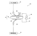
- FIG. 1 is an explanatory diagram showing a schematic configuration of an ethylene production apparatus 101 as a first embodiment of the present disclosure.
- the ethylene production apparatus 101 is an apparatus for producing ethylene from methane-containing gas.
- the ethylene production apparatus 101 includes a ceramic membrane 20, a first catalyst layer 22 formed on one surface of the ceramic membrane 20, a methane supply section 30, an oxygen supply section 32, and a charge transfer section 40.
- the surface of the ceramic film 20 on which the first catalyst layer 22 is formed is referred to as "one surface”
- the surface on the side different from the surface on which the first catalyst layer 22 is formed is referred to as "the other surface”. call.
- the ceramic film 20 and the first catalyst layer 22 are collectively referred to as a "membrane structure 21".
- the ethylene production apparatus 101 further includes a housing (not shown) formed with two spaces partitioned by a partition wall.
- a membrane structure 21 having a ceramic membrane 20 is assembled in the housing described above and constitutes at least a part of the partition walls described above.
- the space on one side where the first catalyst layer 22 is formed is called a first space 24
- the other space of the ceramic membrane 20 is called a first space 24.
- the space on the face side is called a second space 26 .
- the ceramic film 20 is a gas-impermeable dense film made of ceramics. Unlike a film formed on the surface of a carrier, the ceramic film 20 of this embodiment is configured as a self-supporting film that does not have a carrier (base material or support). In addition, the ceramic film 20 contains an oxide ion conductor and exhibits oxide ion conductivity under the operating temperature and operating atmosphere of the ethylene production apparatus 101 .
- the oxide ion conductor contained in the ceramic film 20 for example, at least one oxide ion conductor selected from stabilized zirconia, partially stabilized zirconia, and ceria-based solid solution can be used.
- Stabilized zirconia is zirconia stabilized by dissolving one or more dopants, which are oxides, into zirconium oxide (ZrO 2 ).
- Oxides that can be used as dopants include, for example, yttrium oxide ( Y2O3 ) , scandium oxide ( Sc2O3 ) , ytterbium oxide ( Yb2O3), calcium oxide (CaO), and magnesium oxide (MgO). can be mentioned.
- the stabilized zirconia is preferably selected from yttria-stabilized zirconia (hereinafter also referred to as YSZ) and scandia-stabilized zirconia (hereinafter also referred to as ScSZ).
- YSZ yttria-stabilized zirconia
- ScSZ scandia-stabilized zirconia
- the ceria-based solid solution include cerium-based composite oxides such as gadolinium solid solution ceria (GDC) and samarium solid solution ceria (SDC).
- the ceramic film 20 for example, powders of raw materials such as the oxides described above may be prepared, molded by press molding or the like, and then fired.
- the thickness of the ceramic film 20 can be, for example, 1 to 1000 ⁇ m. The thickness may exceed 1000 ⁇ m as long as the reduction in oxide ion conduction efficiency is within the permissible range.
- the first catalyst layer 22 comprises a methane oxidation coupling catalyst that promotes the methane oxidation coupling reaction that produces ethylene from methane.
- the catalyst provided in the first catalyst layer 22 may be any catalyst that promotes the methane oxidation coupling reaction, and conventionally known mixtures and composite oxides of various oxides can be used.
- the first catalyst layer 22 may further have at least one of proton conductivity, electron conductivity, hole conductivity, and oxide ion conductivity. Even when the first catalyst layer 22 has oxide ion conductivity, the ceramic membrane 20 of the present embodiment has oxide ion conductivity higher than that of the first catalyst layer 22 .
- the methane oxidation coupling catalyst provided in the first catalyst layer 22 has, for example, the general formula (A 1-x A′ x )(Zr 1-yz B y B′ z )O 3 (where A is alkaline earth At least one element selected from group metals, A′ is at least one element selected from lanthanum (La) and yttrium (Y), and B is titanium (Ti) and cerium (Ce). and B' is at least one element selected from yttrium (Y), scandium (Sc), ytterbium (Yb), aluminum (Al), indium (In), and neodymium (Nd).
- the x, the y, and the z are 0 ⁇ x ⁇ 0.4, 0.3 ⁇ (1-z) ⁇ 1, 0 ⁇ y, It can be a composite oxide that satisfies 0 ⁇ (1-yz).
- the above methane oxidation coupling catalyst can be produced, for example, by a complex polymerization method.
- the complex polymerization method is a well-known method capable of producing a composite oxide in which the component elements are well mixed. Specifically, a powder raw material such as a metal nitrate is used, and the powder raw material is weighed so that the mixing ratio of the metal elements in the powder raw material corresponds to the composition of the composite oxide to be produced. is dissolved in water, and an oxycarboxylic acid such as citric acid is added to form a metal oxycarboxylic acid complex. Glycol or the like is added thereto and heated to allow the polymerization reaction to proceed, thereby obtaining a polyester polymer gel. Composite oxide powder is obtained by heat-treating (firing) this polyester polymer gel.
- the method for producing the oxide ion conductor and the methane oxidation coupling catalyst may be a method other than the complex polymerization method described above.
- various methods capable of producing composite oxides such as a solid phase reaction method, a coprecipitation method, or a sol-gel method, can be employed.
- the first catalyst layer 22 can be formed, for example, by making a paste of the methane oxidation coupling catalyst powder using a solvent, coating the paste on the ceramic film 20, and firing the paste.
- the first catalyst layer 22 can be formed by various film forming methods such as, for example, a PVD method (physical vapor deposition method), specifically a PLD method (pulse laser deposition method), a dipping method, a thermal spraying method, a sputtering method, and the like. may be formed on the ceramic film 20 by
- the first catalyst layer 22 may be configured using a supported catalyst in which a methane oxidation coupling catalyst is supported on a porous powder used as a carrier.
- Porous body powders used as carriers include, for example, CeO 2 , ⁇ -Al 2 O 3 , zeolite, SiO 2 , ZrO 2 , Na 2 WO 4 , La 2 O 3 , Cs 2 SO 4 , Sm 2 O 3 and MgO. , SrO, Y2O3, (La , Sr) AlO3 , LaAlO3 .
- the particle size of the porous powder is larger than the particle size of the catalyst supported on the porous powder, and may be, for example, 10 nm to 10 ⁇ m.
- various known methods such as an impregnation method can be used.
- the surface area of the catalyst for the methane oxidation coupling reaction to proceed can be secured widely, and the gas can be well distributed on the catalyst surface. be able to.
- the thickness of the first catalyst layer 22 depends on the degree of catalytic activity of the catalyst included in the first catalyst layer 22, the degree of oxide ion conductivity or electron conductivity of the first catalyst layer 22, and the Depending on the porosity and the like, it may be appropriately set so as to obtain the desired performance for producing ethylene.
- the thickness of the first catalyst layer 22 may be thinner than or thicker than the thickness of the ceramic film 20 .
- the first catalyst layer 22 may be configured using a composite catalyst containing at least one of a metal catalyst and an oxide catalyst in addition to the methane oxidation coupling catalyst. That is, the first catalyst layer 22 may be configured using a composite catalyst in which the above-described methane oxidation coupling catalyst and a metal catalyst or an oxide catalyst are combined and integrated by, for example, mixing the two. . Thereby, the effect of promoting the methane oxidation coupling reaction progressing in the first catalyst layer 22 can be enhanced. Metal catalysts and oxide catalysts are known to promote not only the dehydrogenation reaction involved in the methane oxidation coupling reaction, but also the oxidation reaction.
- metal catalysts include palladium (Pd), copper (Cu), iron (Fe), nickel (Ni), platinum (Pt), indium (In), manganese (Mn), ruthenium (Ru), strontium (Sr ), zinc (Zn), and lithium (Li).
- oxide catalyst for example, an oxide selected from Li 2 ASiO 4 (A is Ca or Sr), Ce 2 (WO 4 ) 3 and CeO 2 can be used.
- the above-described catalyst can be composited using various known methods such as an impregnation method. can be done.
- the methane supply unit 30 supplies the first space 24, which is the space on one side where the first catalyst layer 22 is formed, of the two spaces separated by the ceramic membrane 20 in the ethylene production apparatus 101, It is a device that supplies methane-containing gas.
- methane-containing gas for example, natural gas containing methane as a main component may be used, or methane gas containing substantially no other components may be used.
- the oxygen supply part 32 is a second space which is a space on the other side, which is different from the side on which the first catalyst layer 22 is formed, of the two spaces separated by the ceramic membrane 20 in the ethylene production apparatus 101.
- 26 is a device for supplying an oxygen-containing gas.
- the oxygen-containing gas for example, air may be used, or oxygen gas containing substantially no other components may be used.
- the charge transfer section 40 transfers electrons from one surface of the ceramic film 20 on which the first catalyst layer 22 is formed to the other surface.
- the charge transfer section 40 of this embodiment includes an external circuit 42 connecting one surface and the other surface of the ceramic film 20 and a load section 43 connected to the external circuit 42 . Electrons are transferred from one surface of the ceramic film 20 to the other surface via the external circuit 42 by the electromotive force generated due to the potential difference between the one surface and the other surface of the ceramic film 20.
- the load unit 43 may be any device that extracts electric power generated by the ethylene production apparatus 101 in the production of ethylene.
- the load unit 43 can be various power consumption devices, and may include a power storage device such as a battery or a capacitor that stores generated power.
- the oxidative coupling of methane (OCM) reaction which is a reaction related to ethylene production, progressing in the ethylene production apparatus 101 will be described below.
- OCM oxidative coupling of methane
- the reaction of the following formula (1) proceeds on the first catalyst layer 22 formed on one side of the ceramics membrane 20, and on the other side of the ceramics membrane 20, the following ( The reaction of the formula 2) proceeds, and the reaction of the following formula (3) proceeds in the ethylene production apparatus 101 as a whole.
- methane supplied to the first space 24 and oxide ions supplied from the other side of the ceramic membrane 20 through the inside of the ceramic membrane 20 are used to convert ethylene and water into and electrons proceed (equation (1)).
- the gas containing ethylene and water generated in the first catalyst layer 22 is discharged from the first space 24 through a discharge passage (not shown). Ejected.
- a reaction proceeds to generate oxide ions from oxygen and electrons supplied to the second space 26 (equation (2)). At this time, electrons move from one surface of the ceramic film 20 to the other surface via the external circuit 42 .
- the ethylene production apparatus 101 is shown as having a single plate-like ceramic membrane 20, but the ethylene production apparatus 101 can be of various forms.
- the ceramic film 20 may be formed in a cylindrical shape.
- the first catalyst layer 22 is formed on the inner peripheral surface of the cylindrical ceramic membrane 20, the inner side of the cylinder is the first space 24, and the outer side of the cylindrical ceramic membrane 20 is the outside air.
- the outer side of the cylinder is used as the second space 26 through which air, which is an oxygen-containing gas, flows.
- a channel for supplying the methane-containing gas from the methane supply unit 30 to the first space 24 is connected to one end of the cylindrical ceramic film 20, and the other end of the cylindrical ceramic film 20 is connected to the generated A channel for extracting ethylene from the first space 24 may be connected.
- a plurality of flat ceramic films 20 are laminated, and first spaces 24 and second spaces 26 are alternately provided between the laminated ceramic films 20, and the first spaces 24 in the ceramic films 20 are exposed. It is also possible to form the first catalyst layer 22 on the surface facing the substrate.
- the operation of supplying oxide ions to the first catalyst layer 22 where the methane oxidation coupling reaction proceeds and the operation of supplying the external circuit 42 with the electric charge The operation of moving electrons from the first catalyst layer 22 using the moving part 40 can be continuously performed. Therefore, among the reactions involved in the methane oxidation coupling reaction, the reaction that produces methyl radicals from methane can be promoted, and the efficiency of the overall reaction that produces ethylene from methane can be increased.
- the reaction of generating methyl radicals from methane is further described below.
- Equation (4) represents the reaction of generating methyl radicals from methane
- Equation (5) represents the reaction of coupling methyl radicals to generate ethane
- Equation (6) represents the generation of ethylene from ethane. shows a reaction that
- the covalent bond between carbon atoms and hydrogen atoms in methane has a bond energy of 104 kcal/mol and is an extremely stable bond. Therefore, in the methane oxidation coupling reaction, the reaction represented by the formula (4), in which methyl radicals are generated from methane having a stable covalent bond as described above, is generally considered to be the rate-determining process. Therefore, in order to promote the methane oxidative coupling reaction, it is important to promote the reaction that generates the methyl radical.
- the ethylene production apparatus 101 of the present embodiment uses a ceramic membrane 20 having oxide ion conductivity, supplies methane to a first catalyst layer 22 provided on one surface of the ceramic membrane 20, and supplies methane to the ceramic membrane 20.
- Oxygen is supplied to the other surface to move electrons from one surface of the ceramic film 20 to the other surface. Therefore, when the methane oxidation coupling reaction proceeds, oxide ions are supplied to the first catalyst layer 22 through the ceramic film 20, and electrons are extracted from the first catalyst layer 22 by the charge transfer section 40. promotes the reaction represented by the formula (4). In this way, the rate-determining reaction of generating methyl radicals is promoted, and as a result, the overall reaction for producing ethylene from methane is promoted, and the production efficiency of ethylene can be enhanced.
- the production efficiency of ethylene is improved by providing the first catalyst layer 22 having a methane oxidation coupling catalyst on the ceramic membrane 20 having relatively high oxide ion conductivity. increasing.
- the methane oxidation coupling catalyst for example, as described above, the general formula (A 1-x A′ x )(Zr 1-yz B y B′ z )O 3 (where A is alkaline earth At least one element selected from group metals, A′ is at least one element selected from lanthanum (La) and yttrium (Y), and B is titanium (Ti) and cerium (Ce).
- B' is at least one element selected from yttrium (Y), scandium (Sc), ytterbium (Yb), aluminum (Al), indium (In), and neodymium (Nd). and the x, the y, and the z are 0 ⁇ x ⁇ 0.4, 0.3 ⁇ (1-z) ⁇ 1, 0 ⁇ y, A complex oxide that satisfies 0 ⁇ (1-yz) can be used.
- Such a methane oxidation coupling catalyst has relatively high activity to promote the reaction of generating methyl radicals from methane, and as a result, has relatively high activity to generate C2 hydrocarbons such as ethylene from methane. , the production efficiency of ethylene can be further increased.
- the ethylene production apparatus 101 of the present embodiment power generation is performed along with the reaction for producing ethylene. If the generated electric power is used, for example, in the methane supply unit 30 and the oxygen supply unit 32 of the ethylene production apparatus 101, the energy efficiency of the ethylene production apparatus 101 as a whole can be improved. Also, the generated electric power may be used in devices other than the ethylene production device 101 .
- FIG. 2 is an explanatory diagram showing a schematic configuration of the ethylene production apparatus 102 of the second embodiment.
- the ethylene production apparatus 102 has the same structure as the ethylene production apparatus 101 of the first embodiment, except that the ceramic film 120 is provided instead of the ceramic film 20 .
- the ceramic film 120 and the first catalyst layer 22 are also collectively referred to as a "membrane structure 121".
- the ceramic film 120 provided in the ethylene production apparatus 102 is a gas-impermeable dense film made of ceramics, and is configured as a self-supporting film. Moreover, the ceramic film 120 contains a proton conductor and exhibits proton conductivity under the operating temperature and atmosphere of the ethylene production apparatus 102 .
- Various conventionally known proton conductors can be used as the proton conductor contained in the ceramic membrane 120 .
- perovskite-type composite oxides such as BaZrO 3 system, BaCeO 3 , SrZrO 3 system, or SrCeO 3 system can be used.
- Such a composite oxide can be produced, for example, by the complex polymerization method, solid phase reaction method, coprecipitation method, or sol-gel method described above.
- the methane oxidation coupling reaction which is a reaction related to ethylene production, progressing in the ethylene production apparatus 102 will be described below.
- the reaction of the following formula (7) proceeds on the first catalyst layer 22 formed on one side of the ceramic membrane 120, and on the other side of the ceramic membrane 120, the following ( The reaction of the formula 8) proceeds, and the reaction of the following formula (9) proceeds throughout the ethylene production apparatus 102 .
- a reaction proceeds in which ethylene, protons, and electrons are generated from the methane supplied to the first space 24 (equation (7)).
- the electrons generated by the reaction move from one surface of the ceramic film 120 to the other surface through the external circuit 42, and also move through the inside of the ceramic film 120 to Protons generated in the reaction move from one surface to the other surface.
- oxygen supplied to the second space 26 electrons supplied through the external circuit 42, and protons supplied through the inside of the ceramic film 120 are used to , a reaction that produces water proceeds (equation (8)).
- the ceramic film 120 having proton conductivity is used to discharge protons from the first catalyst layer 22 where the methane oxidation coupling reaction proceeds, and the charge transfer section 40 having the external circuit 42. can be used to continuously transfer electrons from the first catalyst layer 22 . Therefore, among the reactions involved in the methane oxidation coupling reaction, the reaction that produces methyl radicals from methane can be promoted, and the efficiency of the overall reaction that produces ethylene from methane can be increased.
- the reaction of generating methyl radicals from methane is further described below.
- Equation (10) represents the reaction of generating methyl radicals from methane
- Equation (11) represents the reaction of coupling methyl radicals to generate ethane in the same manner as Equation (5)
- Equation 12 shows the reaction in which ethylene is produced from ethane.
- the reaction represented by formula (10), which generates methyl radicals from methane having stable covalent bonds is generally considered to be the rate-limiting process.
- the ethylene production apparatus 102 of the second embodiment uses a ceramic membrane 120 having proton conductivity, supplies methane to the first catalyst layer 22 provided on one side of the ceramic membrane 120, and supplies methane to the other side of the ceramic membrane 120. oxygen is supplied to the surface of the ceramic film 20 to move electrons from one surface to the other surface of the ceramic film 20 . Therefore, when the methane oxidation coupling reaction proceeds, protons are discharged from the first catalyst layer 22 through the ceramic film 20, and electrons are extracted from the first catalyst layer 22 by the charge transfer section 40. (10) The reaction represented by the formula is promoted. In this way, the rate-determining reaction of generating methyl radicals is promoted, and as a result, the overall reaction for producing ethylene from methane is promoted, and the production efficiency of ethylene can be enhanced.
- FIG. 3 is an explanatory diagram showing a schematic configuration of the ethylene production apparatus 103 of the third embodiment.
- the ethylene production apparatus 103 has the same structure as the ethylene production apparatus 101 of the first embodiment, except that the second catalyst layer 28 is further provided on the other surface of the ceramics membrane 20 .
- the ceramic film 20, the first catalyst layer 22, and the second catalyst layer 28 are collectively referred to as the "film structure 23".
- the second catalyst layer 28 included in the ethylene production apparatus 103 of the third embodiment includes a catalyst that promotes the reaction represented by formula (2).
- the catalyst provided in the second catalyst layer 28 is not particularly limited as long as it promotes the reaction of formula (2).
- an oxide having oxide ion-electron mixed conductivity is preferable, and for example, La 0.6 Sr 0.4 Co 0.2 Fe 0.8 O 3 can be used. can.
- La 0.6 Sr 0.4 Co 0.2 Fe 0.8 O 3 can be used as the catalyst provided in the second catalyst layer 28.
- such a composite oxide can be obtained by, for example, the above-described complex polymerization method, solid phase reaction method, coprecipitation method, or It can be manufactured by a sol-gel method. Then, using the obtained catalyst, the second catalyst layer 28 may be formed on the ceramic film 20 in the same manner as the first catalyst layer 22 .
- FIG. 4 is an explanatory diagram showing a schematic configuration of the ethylene production apparatus 104 of the fourth embodiment.
- the ethylene production apparatus 104 has the same structure as the ethylene production apparatus 102 of the second embodiment, except that the second catalyst layer 28 is further provided on the other surface of the ceramics membrane 120 .
- the ceramic film 120, the first catalyst layer 22, and the second catalyst layer 28 are collectively referred to as a "membrane structure 123".
- the second catalyst layer 28 provided in the ethylene production apparatus 104 of the fourth embodiment includes a catalyst that promotes the reaction shown in formula (8).
- the catalyst provided in the second catalyst layer 28 is not particularly limited as long as it promotes the reaction of formula (8).
- an oxide having oxide ion-electron mixed conductivity is preferable, and for example, La 0.6 Sr 0.4 Co 0.2 Fe 0.8 O 3 can be used. can.
- the second catalyst layer 28 of the fourth embodiment can be produced in the same manner as the second catalyst layer 28 of the third embodiment.
- FIG. 5 is an explanatory diagram showing a schematic configuration of the ethylene production apparatus 105 of the fifth embodiment. Except that the ethylene production apparatus 105 includes an inert gas supply unit 34 that supplies an inert gas to the second space 26 instead of the oxygen supply unit 32 that supplies the oxygen-containing gas to the second space 26. It has the same structure as the ethylene production apparatus 104 of the fourth embodiment.
- the inert gas supplied by the inert gas supply unit 34 may be any gas that does not affect the reaction progressing on the second catalyst layer 28, and for example, helium, argon, nitrogen, or the like can be used.
- the second catalyst layer 28 provided in the ethylene production apparatus 105 is a catalyst that promotes the reaction of formula (14) described later, instead of the reaction of formula (8) that proceeds in the second catalyst layer 28 of the fourth embodiment.
- the catalyst provided in the second catalyst layer 28 of the fifth embodiment is not particularly limited as long as it promotes the reaction of formula (14).
- an oxide having oxide ion-electron mixed conductivity is preferable, and for example, La 0.6 Sr 0.4 Co 0.2 Fe 0.8 O 3 can be used. can.
- the second catalyst layer 28 of the fifth embodiment can be produced in the same manner as the second catalyst layer 28 of the fourth embodiment.
- reaction of the following formula (13) proceeds in the first catalyst layer 22 formed on one surface of the ceramic film 120, and the ceramic film 120
- the reaction of the following formula (14) proceeds, and the reaction of the following formula (15) proceeds in the entire ethylene production apparatus 102 .
- the reaction in which ethylene, protons, and electrons are generated from the methane supplied to the first space 24 proceeds in the same manner as in the reaction of formula (7) in the second and fourth embodiments. ((13) formula).
- the electrons generated by the reaction move from one surface of the ceramic film 120 to the other surface through the external circuit 42, and also move through the inside of the ceramic film 120 to Protons generated in the reaction move from one surface to the other surface.
- the electrons supplied through the external circuit 42 and the protons supplied through the inside of the ceramic film 120 are used to progress a reaction that produces hydrogen ((14 )formula).
- the hydrogen partial pressure in the second space 26 can be reduced to maintain the progress of the reaction of formula (14).
- the methane supply unit 30 supplies the methane-containing gas to the first space 24, and the inert gas supply unit 34 supplies the inert gas to the second space 26. Then, ethylene is produced in the first catalyst layer 22, and hydrogen and electric power are extracted from the ethylene production unit 105 together with ethylene.
- the reaction that proceeds in the first catalyst layer 22 shown by the formula (13) is, for example, from the already described formula (10) (12) It is thought to proceed through a plurality of reactions as shown in formula (12).
- the ethylene production apparatus 105 of the fifth embodiment hydrogen is produced in the second catalyst layer 28 as ethylene is produced in the first catalyst layer 22 . Therefore, the obtained hydrogen can be used, for example, as fuel for combustion reaction or power generation to generate energy such as thermal energy and electrical energy.
- a decompression section for decompressing the second space 26 may be provided.
- the decompression unit can be composed of, for example, a decompression pump. Even with such a configuration, it is possible to reduce the partial pressure of hydrogen generated in the second catalyst layer 28 in the second space 26, as in the case where the inert gas supply unit 34 is provided. The progress of the reaction of formula can be maintained.
- FIG. 6 is an explanatory diagram showing a schematic configuration of the ethylene production apparatus 106 of the sixth embodiment.
- the ethylene production apparatus 106 includes a carbon dioxide supply unit 36 that supplies a carbon dioxide-containing gas to the second space 26 instead of the oxygen supply unit 32 that supplies the oxygen-containing gas to the second space 26. It has the same structure as the ethylene production apparatus 104 of the fourth embodiment, except for the provision.
- the second catalyst layer 28 provided in the ethylene production apparatus 106 is a catalyst that promotes the reaction of formula (17), which will be described later, instead of the reaction of formula (8) that proceeds in the second catalyst layer 28 of the fourth embodiment.
- the catalyst provided in the second catalyst layer 28 of the sixth embodiment is not particularly limited as long as it promotes the reaction of formula (17).
- Nickel for example, can be used as the catalyst included in the second catalyst layer 28 .
- nickel oxide powder is made into a paste using a solvent, and the paste is applied to the other surface of the ceramic film 120 and fired to form the second catalyst layer 28 . can be done.
- the reaction of the following formula (16) proceeds in the first catalyst layer 22 formed on one surface of the ceramic film 120, and the ceramic film 120
- the reaction of the following formula (17) proceeds, and the reaction of the following formula (18) proceeds in the entire ethylene production apparatus 106 .
- the reaction in which ethylene, protons, and electrons are generated from the methane supplied to the first space 24 proceeds in the same manner as in the reaction of formula (7) in the second and fourth embodiments. ((16) formula).
- the electrons generated by the reaction move from one surface of the ceramic film 120 to the other surface through the external circuit 42, and also move through the inside of the ceramic film 120 to Protons generated in the reaction move from one surface to the other surface.
- carbon dioxide supplied to the second space 26 electrons supplied via the external circuit 42, and protons supplied via the inside of the ceramic membrane 120 are used.
- the reaction that produces methane and water proceeds (equation (17)).
- the methane supply unit 30 supplies the methane-containing gas to the first space 24 and the carbon dioxide supply unit 36 supplies carbon dioxide to the second space 26
- Ethylene is produced in the first catalyst layer 22, and methane and electric power are taken out from the ethylene production unit 105 together with ethylene.
- the reaction that proceeds in the first catalyst layer 22 shown by the formula (16) is, for example, from the already described formula (10) (12) It is thought to proceed through a plurality of reactions as shown in formula (12).
- methane is produced in the second catalyst layer 28 as ethylene is produced in the first catalyst layer 22 . Therefore, it becomes possible to generate energy by using the obtained methane as a fuel for combustion reaction, for example, or to use it as a material for generating other compounds.
- FIG. 7 is an explanatory diagram showing a schematic configuration of the ethylene production apparatus 107 of the seventh embodiment.
- the ethylene production apparatus 107 has the same structure as the ethylene production apparatus 103 of the third embodiment, except that it has a ceramic film 220 instead of the ceramic film 20 and does not have the charge transfer section 40 including the external circuit 42. ing.
- the ceramic film 220, the first catalyst layer 22, and the second catalyst layer 28 are collectively referred to as a "membrane structure 223".
- the ceramic membrane 220 provided in the ethylene production apparatus 107 is a gas-impermeable, dense membrane made of ceramics, and is configured as a self-supporting membrane.
- the ceramic film 220 further contains at least one of an electron conductor and a hole conductor. material ionic conductivity and at least one of electronic and hole conductivity;
- the electron conductivity and the hole conductivity are collectively referred to as “electron conductivity”
- the electron conductor and the hole conductor are collectively referred to as "electron conductor”.
- the ceramic film 220 can be made of, for example, a mixture of an oxide ion conductor and an electron conductor.
- the ceramic film 220 may be formed of a composite oxide (hereinafter also referred to as a first mixed-conducting oxide) having both oxide ion conductivity and electronic conductivity.
- ceramic film 220 may be formed from a mixture of at least one of an oxide ion conductor and an electronic conductor and a first mixed conducting oxide.
- the oxide ion conductor contained in the ceramic film 220 for example, the same oxide ion conductor as the ceramic film 20 of the first embodiment or the third embodiment may be used.
- the electron conductor contained in the ceramic film 220 is, for example, an oxide electron conductor having a perovskite structure, an oxide electron conductor having a spinel crystal structure, and an electron conductor selected from metal materials such as noble metals. can be used.
- an oxide electron conductor having a perovskite structure for example, an LSM-based oxide in which Sr is added to the La site in a LaMnO 3 -based compound, or a composite oxide such as SrTiO 3 can be used.
- at least one electron conductor selected from an electron conductor represented by the following formula (19) and an electron conductor represented by the following formula (20) may be used.
- Alkaline earth metal M in formula (19) is preferably strontium (Sr) or calcium (Ca).
- M is an element selected from alkaline earth metals excluding magnesium (Mg), and 0 ⁇ x ⁇ 0.3.
- Examples of the first mixed conductive oxide included in the ceramic film 220 include an LSGF - based oxide having a perovskite structure in which Sr is added to the La site and Fe is added to the Ga site in a LaGaO3-based compound, and SrCoO Among the 3 -based compounds, a BSCF-based oxide having a perovskite structure in which Ba is added to the Sr site and Fe is added to the Co site can be mentioned.
- an oxide having a layered perovskite structure, an oxide having a fluorite structure, an oxide having an oxyapatite structure, an oxide having a melilite structure, or the like can be used as the first mixed conducting oxide.
- such a composite oxide can be obtained by, for example, the above-described complex polymerization method, solid phase reaction method, coprecipitation method, method, or a sol-gel method. Then, a mixed powder obtained by mixing an oxide ion conductor and an electron conductor or a powder containing a first mixed conductive oxide is obtained, molded by press molding or the like, and then sintered to produce a ceramic film 220 . do it.
- the electrons generated in the reaction of formula (1) pass through the inside of the ceramic film 220 to the second catalyst layer. 28 and subjected to the reaction of formula (2).
- the ceramic film 220 functions as a charge transfer section.
- the ceramic film 220 constitutes the charge transfer section and does not require the external circuit 42, the device configuration can be simplified.
- FIG. 8 is an explanatory diagram showing a schematic configuration of the ethylene production apparatus 108 of the eighth embodiment.
- the ethylene production apparatus 108 has the same structure as the ethylene production apparatus 104 of the fourth embodiment except that it has a ceramic film 320 instead of the ceramic film 120 and does not have the charge transfer section 40 including the external circuit 42. ing.
- the ceramic film 320, the first catalyst layer 22, and the second catalyst layer 28 are collectively referred to as a "membrane structure 323".
- the ceramic membrane 320 provided in the ethylene production apparatus 108 is a gas-impermeable, dense membrane made of ceramics, and is configured as a self-supporting membrane.
- the ceramic film 320 exhibits proton conductivity and electronic conductivity under the operating temperature and atmosphere of the ethylene production apparatus 108 .
- the ceramic film 320 can be formed, for example, from a mixture of a proton conductor and an electron conductor.
- the ceramic film 320 may be formed of a composite oxide having both proton conductivity and electron conductivity (hereinafter also referred to as a second mixed-conducting oxide).
- the ceramic membrane 320 may be formed from a mixture of at least one of a proton conductor and an electron conductor and a second mixed conducting oxide.
- the proton conductor contained in the ceramic membrane 320 for example, the same proton conductor as the ceramic membrane 120 of the second and fourth to sixth embodiments may be used.
- the electron conductor contained in the ceramic film 320 the same electron conductor as the ceramic film 220 of the seventh embodiment may be used. Then, a mixed powder of a proton conductor and an electron conductor or a powder containing a second mixed conductive oxide is obtained, molded by press molding or the like, and then sintered to fabricate the ceramic film 320. good.
- the electrons generated in the reaction of formula (7) pass through the inside of the ceramic film 320 to the second catalyst layer. 28 and subjected to the reaction of formula (8).
- the ceramic film 320 functions as a charge transfer section.
- the ceramic film 320 constitutes the charge transfer section and the external circuit 42 is not required, the configuration of the device can be simplified.
- FIG. 9 is an explanatory diagram showing a schematic configuration of the ethylene production apparatus 109 of the ninth embodiment.
- the ethylene production apparatus 109 has the same structure as the ethylene production apparatus 105 of the fifth embodiment, except that it has a ceramic film 320 instead of the ceramic film 120 and does not have the charge transfer section 40 including the external circuit 42. ing.
- a ceramic film 320 included in the ethylene production apparatus 109 of the ninth embodiment is formed in the same manner as the ceramic film 320 of the eighth embodiment.
- the electrons generated by the reaction of formula (13) pass through the inside of the ceramics membrane 320 to the second catalyst layer. 28 and subjected to the reaction of formula (14).
- the ceramic film 320 functions as a charge transfer section.
- a decompression section for decompressing the second space 26 may be provided instead of the inert gas supply section 34.
- the decompression unit can be composed of, for example, a decompression pump. Even with such a configuration, it is possible to reduce the partial pressure of hydrogen generated in the second catalyst layer 28 in the second space 26, as in the case where the inert gas supply unit 34 is provided. The progress of the reaction of formula can be maintained.
- FIG. 10 is an explanatory diagram showing a schematic configuration of an ethylene production apparatus 110 of the tenth embodiment.
- the ethylene production apparatus 110 has the same structure as the ethylene production apparatus 106 of the sixth embodiment, except that it has a ceramic film 320 instead of the ceramic film 120 and does not have the charge transfer section 40 including the external circuit 42. ing.
- a ceramic film 320 provided in the ethylene production apparatus 110 of the tenth embodiment is formed in the same manner as the ceramic film 320 of the eighth embodiment.
- the electrons generated in the reaction of formula (16) pass through the inside of the ceramics membrane 320 to the second catalyst layer. 28 and subjected to the reaction of formula (17).
- the ceramic film 320 functions as a charge transfer section.
- the ethylene production apparatus 110 of the tenth embodiment methane is produced in the second catalyst layer 28 as ethylene is produced in the first catalyst layer 22 . Therefore, the methane obtained can be used for the generation of energy or as a material for the production of other compounds. Furthermore, since the ceramic film 320 constitutes the charge transfer section and the external circuit 42 is not required, the configuration of the device can be simplified.
- FIG. 11 is an explanatory diagram showing a schematic configuration of an ethylene production apparatus 111 of the eleventh embodiment.
- the ethylene production apparatus 111 has the same structure as the ethylene production apparatus 106 of the sixth embodiment, except that it further includes a methane recovery unit 38 .
- the methane recovery unit 38 provided in the ethylene production apparatus 111 converts methane produced in the second catalyst layer 28 provided on the other surface of the ceramics membrane 120 into a methane-containing gas supplied to the first space 24 by the methane supply unit 30. to mix.
- the methane recovery section 38 of the eleventh embodiment connects the outlet section from which methane is discharged from the second space 26 of the ethylene production apparatus 111 to the methane supply section 30 and the first space 24 to collect methane. It is a channel that connects with the channel in which the contained gas flows.
- the methane generated in the second catalyst layer 28 accompanying the generation of ethylene in the first catalyst layer 22 is led to the first space 24 by the methane recovery unit 38. and is used for ethylene production. Therefore, compared to the case where the methane recovery unit 38 is not provided, the amount of methane to be supplied from the methane supply unit 30 for the production of ethylene can be reduced, and the utilization efficiency of methane can be improved.
- the methane recovery unit 38 is applied to the ethylene production apparatus 106 of the sixth embodiment, but it may have a different configuration.
- the methane recovery section 38 similar to that of the eleventh embodiment may be provided.
- the amount of methane to be supplied from the methane supply unit 30 is reduced compared to the case where the methane recovery unit 38 is not provided. A similar effect of reducing the amount of methane and improving the utilization efficiency of methane can be obtained.
- the charge transfer section 40 is driven by the electromotive force generated due to the potential difference between one surface and the other surface of the ceramic film. , the electrons are moved from one surface of the ceramic film to the other surface via the external circuit 42, but a different configuration may be used.
- an external power supply may be connected to the external circuit 42 instead of the load section 43 .
- Electrons may be moved from one surface of the ceramic film to the other surface.
- the ceramic film is a self-supporting film as shown in FIGS. 1 to 11, but may have a different structure.
- the ceramic film may be a film formed on the surface of a porous carrier (substrate, support).
- the ceramic film may be formed as a gas-impermeable dense film on the porous carrier by, for example, a PVD method such as a PLD method, a dipping method, a thermal spraying method, a sputtering method, or the like.
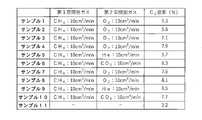
- FIG. 12 is an explanatory diagram showing the results of examining the performance of 11 types of ethylene production apparatuses, Samples 1 to 11.
- the configuration and manufacturing method of each sample, and the results of performance evaluation will be described below.
- Samples 1 to 10 have configurations corresponding to the ethylene production apparatuses of the first to tenth embodiments, respectively.
- Sample 11 is a comparative example.
- the ceramic film 20 of Sample 1 was produced using yttria-stabilized zirconia (YSZ) as an oxide ion conductor. Specifically, TZ-8YS manufactured by Tosoh Corporation was used. The YSZ powder was press-molded into a disk shape by a hydraulic press and sintered at 1400° C. for 6 hours. The resulting sintered body was ground by a surface grinder to a thickness of 0.15 mm to obtain a ceramic film 20 .
- YSZ yttria-stabilized zirconia
- the first catalyst layer 22 of sample 1 was produced using BaZr 0.4 Sc 0.6 O 3 as a catalyst that promotes synthesis of ethylene from methane.
- BaZr 0.4 Sc 0.6 O 3 was produced by a complex polymerization method as follows. Barium nitrate (manufactured by FUJIFILM Wako Pure Chemical Industries, Ltd.), zirconyl nitrate (manufactured by FUJIFILM Wako Pure Chemical Industries, Ltd.), and scandium nitrate (manufactured by Alfa Aesar) were used as raw material powders. These raw material powders were weighed so that the ratio of the metal elements was the composition ratio in the composition formula BaZr 0.4 Sc 0.6 O 3 .
- the ceramic membrane 120 of Sample 2 was produced using BaZr 0.8 Y 0.2 O 3 as a proton conductor.
- BaZr 0.8 Y 0.2 O 3 was produced by a solid phase reaction method as follows. Barium carbonate (manufactured by Sakai Chemical Industry Co., Ltd.), zirconium oxide (manufactured by Daiichi Kigenso Kagaku Kogyo Co., Ltd.), and yttrium oxide (manufactured by Shin-Etsu Chemical Co., Ltd.) were used as raw material powders. These raw material powders were weighed so that the ratio of the metal elements was the composition ratio in the composition formula BaZr 0.8 Y 0.2 O 3 .
- the mixture was pulverized and mixed in ethanol for 15 hours to obtain a slurry.
- the obtained slurry was dried in a hot water bath to obtain a mixed powder, and the obtained mixed powder was calcined at 1300° C. for 6 hours to obtain a BaZr 0.8 Y 0.2 O 3 powder.
- the obtained powder was pressed into a disk shape by a hydraulic press and sintered at 1600° C. for 10 hours.
- the resulting sintered body was ground by a surface grinder to a thickness of 0.15 mm to obtain a ceramic film 120 .
- a first catalyst layer 22 was formed on one surface of this ceramic film 120 in the same manner as in sample 1, and a film structure 121 of sample 2 was produced.
- Sample 3 The ethylene production apparatus of Sample 3, as shown in FIG. a second catalyst layer 28 provided on the surface of the membrane structure 23;
- the second catalyst layer 28 of sample 3 was produced using La 0.6 Sr 0.4 Co 0.2 Fe 0.8 O 3 as a catalyst that accelerates the reaction of formula (2).
- La 0.6 Sr 0.4 Co 0.2 Fe 0.8 O 3 was produced by a solid phase reaction method as follows. As raw material powders, lanthanum oxide (manufactured by Fujifilm Wako Pure Chemical Industries, Ltd.), strontium carbonate (manufactured by Kojundo Chemical Laboratory Co., Ltd.), cobalt oxide (manufactured by Kojundo Chemical Laboratory Co., Ltd.), and iron oxide (manufactured by Kojundo Chemical Laboratory Co., Ltd.) Kojundo Chemical Laboratory Co., Ltd.) was used.
- lanthanum oxide manufactured by Fujifilm Wako Pure Chemical Industries, Ltd.
- strontium carbonate manufactured by Kojundo Chemical Laboratory Co., Ltd.
- cobalt oxide manufactured by Kojundo Chemical Laboratory Co., Ltd.
- iron oxide manufactured by Kojundo Chemical Laboratory Co
- a catalyst paste 2 was prepared in the same manner as the catalyst paste 1 of the first catalyst layer 22 described in the sample 1.
- a second catalyst layer 28 was formed in the same manner as the first catalyst layer 22 on the other surface of a film structure similar to the film structure 21 of sample 1, and the film structure of sample 3 was formed.
- a body 23 was produced.
- Sample 4 The ethylene production apparatus of Sample 4, as shown in FIG. and a membrane structure 123 having a second catalyst layer 28 provided on the substrate.
- the second catalyst layer 28 of sample 4 contains La 0.6 Sr 0.4 Co 0.2 Fe 0.8 O, similar to the second catalyst layer 28 of sample 3, as a catalyst that promotes the reaction of formula (8). 3 .
- a second catalyst layer 28 was formed in the same manner as the second catalyst layer 28 of Sample 3 on the other surface of the membrane structure 121 similar to that of Sample 2, and a membrane structure 123 of Sample 4 was produced.
- Sample 5 The ethylene production apparatus of Sample 5, as shown in FIG. and a membrane structure 123 having a second catalyst layer 28 provided on the substrate.
- the second catalyst layer 28 of sample 5 contains La 0.6 Sr 0.4 Co 0.2 Fe as a catalyst that promotes the reaction of formula (14), similarly to the second catalyst layers 28 of samples 3 and 4. Made with 0.8 O3. That is, the film structure 123 of Sample 5 has the same configuration as the film structure 123 of Sample 4. FIG.
- sample 6 The ethylene production apparatus of sample 6, as shown in FIG. and a membrane structure 123 having a second catalyst layer 28 provided on the substrate.
- the second catalyst layer 28 of sample 6 was produced using nickel as a catalyst that accelerates the reaction of formula (17).
- nickel oxide manufactured by Kojundo Chemical Laboratory Co., Ltd.
- the catalyst paste 2 of sample 6 was prepared in the same manner as the catalyst paste 2 of sample 3.
- the second catalyst layer 28 was formed on the other surface of the membrane structure 121 similar to that of sample 2 in the same manner as the second catalyst layer 28 of sample 3, and the membrane structure of sample 6 was formed. 123 was made.
- Sample 7 The ethylene production apparatus of Sample 7, as shown in FIG. a membrane structure 223 having a second catalyst layer 28 provided on the other side of the membrane 220;
- the ceramic film 220 of sample 7 was produced by mixing an oxide ion conductor and an electron conductor.
- Yttria-stabilized zirconia (YSZ) similar to the ceramic film 20 of Sample 1 was used as an oxide ion conductor.
- La 0.8 Sr 0.2 CrO 3 was used as an electron conductor.
- La 0.8 Sr 0.2 CrO 3 contains lanthanum oxide (manufactured by Fujifilm Wako Pure Chemical Industries, Ltd.), strontium carbonate (manufactured by Kojundo Chemical Laboratory Co., Ltd.), and chromium oxide (manufactured by Kojundo Chemical Laboratory Co., Ltd.) as raw material powders. (manufactured by Kagaku Kenkyusho Co., Ltd.), and manufactured by the solid-phase reaction method described above.
- Sample 8 The ethylene production apparatus of Sample 8, as shown in FIG. and a second catalyst layer 28 provided on the other side of the membrane structure 323 .
- the ceramic film 320 of sample 8 was produced by mixing a proton conductor and an electron conductor.
- a proton conductor BaZr 0.8 Y 0.2 O 3 similar to the ceramic film 120 of sample 2 was used.
- an electron conductor La 0.8 Sr 0.2 CrO 3 similar to the ceramic film 220 of Sample 7 was used.
- the first catalyst layer 22 described above is formed on one surface of this ceramic film 320, and the second catalyst layer 28 similar to the second catalyst layer 28 of Sample 4 is formed on the other surface of the ceramic film 320. Then, a film structure 323 of sample 8 was produced.
- Sample 9 The ethylene production apparatus of Sample 9, as shown in FIG. and a second catalyst layer 28 provided on the other side of the membrane structure 323 .
- the ceramic film 320 of sample 9 was produced in the same manner as the ceramic film 320 of sample 8.
- the first catalyst layer 22 described above is formed on one surface of the ceramic film 320, and the second catalyst layer 28 similar to the second catalyst layer 28 of Sample 5 is formed on the other surface of the ceramic film 320. Then, a film structure 323 of sample 9 was produced.
- the ethylene production apparatus of sample 10 includes a ceramic membrane 320 having proton conductivity and electronic conductivity, a first catalyst layer 22 provided on one side of the ceramic membrane 320, and a ceramic membrane 320. and a second catalyst layer 28 provided on the other side of the membrane structure 323 .
- the ceramic film 320 of sample 10 was produced in the same manner as the ceramic films 320 of sample 8 and sample 9.
- the first catalyst layer 22 described above is formed on one surface of this ceramic film 320, and the second catalyst layer 28 similar to the second catalyst layer 28 of sample 6 is formed on the other surface of the ceramic film 320.
- the film structure 323 of sample 10 was produced.
- sample 11 The ethylene production apparatus of sample 11 uses only a methane oxidation coupling catalyst without using a ceramic membrane. As the methane oxidation coupling catalyst of sample 11, the catalyst powder 1 produced for forming the first catalyst layer 22 of sample 1 was used.
- FIG. 13 is an explanatory diagram showing a schematic configuration of a measuring device 50 for measuring the C 2 yield in the ethylene production plants of Samples 1 to 10.
- FIG. 13 shows the state of measurement using the film structure 21 of sample 1 as an example, but the measurement apparatuses of other samples have the same configuration.
- the measuring device 50 includes two outer alumina tubes 53 and 55, two inner alumina tubes 52 and 54, and an electric furnace 56.
- Two outer alumina tubes 53, 55 are arranged one above the other, sandwiching the membrane structure of each sample between which measurements are taken.
- a gold thin film having an inner diameter of 10 mm is applied on both sides of the ceramic membrane at the outer periphery of the membrane structure where the ceramic membrane is exposed without being covered with the catalyst layer.
- a ring 51 was placed. Then, the outer alumina tubes 53 and 55 were pressed against the ceramic film via the thin film ring 51, and the temperature was raised to 1050° C. to soften the gold and secure the gas sealing property.
- An inner alumina tube 52 was arranged inside the outer alumina tube 53
- an inner alumina tube 54 was arranged inside the outer alumina tube 55 .
- the space above the membrane structure in the outer alumina tube 53 is the first space 24
- the space above the membrane structure in the outer alumina tube 55 is the second space 26 .
- the outer alumina tubes 53 , 55 with the membrane structure attached were arranged in the electric furnace 56 so that the membrane structure was arranged in the soaking part of the electric furnace 56 .
- each measuring device 50 for each sample assembled as described above methane was supplied to the first space 24 through the inner alumina tube 52 at a flow rate of 10 cm 3 /min.
- the ethylene-containing gas generated by the methane oxidation coupling reaction progressing in the first catalyst layer 22 passes from the first space 24 through the flow path between the inner alumina tube 52 and the outer alumina tube 53 to the first It was discharged from the discharge channel 57 .
- the gas shown in FIG. 12 was supplied to the second space 26 through the inner alumina tube 54 .
- the gas that has undergone the reaction progressing on the surface of the membrane structure exposed in the second space 26 is discharged from the second space 26 via the flow path between the inner alumina tube 54 and the outer alumina tube 55 to the second discharge. It was discharged from the channel 58 .
- the temperature of the electric furnace 56 was set to 700.degree.
- the measuring device 50 for samples 1 to 6 is provided with an external circuit 42, and a DC electronic load device (FK-160L2Z, manufactured by Takasago Seisakusho Co., Ltd.) is used to measure the current density. was set to 0.25 A/cm 2 .
- the gas discharged from the first space 24 and the gas discharged from the second space 26 are analyzed using micro gas chromatography (Agilent Technologies, 3000A) to obtain the C2 yield. rice field. The C2 yields obtained are shown in conjunction with FIG.
- the gas discharged from the first space 24 also contains ethane generated by the formulas (5) and (11), but normally the reactions of the formulas (6) and (12) further proceed. Therefore, most of the C2 hydrocarbons obtained are ethylene (data not shown).
- the ethylene production apparatus of Samples 1 to 10 comprising the ceramic membrane 20, the first catalyst layer 22, and the charge transfer section 40 was the ethylene production apparatus of Sample 11 using a fixed bed flow reactor. showed higher C2 yields compared to .
- the provision of the second catalyst layer 28 further improved the C2 yield.
- sample 21 The catalyst (BaZr 0.8 Sc 0.2 O 3 ) of sample 21 was produced by a complex polymerization method. Barium nitrate (manufactured by FUJIFILM Wako Pure Chemical Industries, Ltd.), zirconyl nitrate (manufactured by FUJIFILM Wako Pure Chemical Industries, Ltd.), and scandium nitrate (manufactured by Alfa Aesar) were used as raw material powders. These raw material powders were weighed so that the ratio of the metal elements was the composition ratio in the composition formula BaZr 0.8 Sc 0.2 O 3 .
- Samples 22-54 The kind and the amount to be weighed of the raw material powder of the catalyst were adjusted so as to achieve the composition ratios of the composition formulas of samples 22 to 54 shown in FIGS. Catalyst powders 22 to 54 were obtained in the same manner as sample 21, except that the temperature shown in FIG. 15 was used.
- Barium nitrate (Fujifilm Wako Pure Chemical Co., Ltd.) ), zirconyl nitrate (manufactured by Fujifilm Wako Pure Chemical Industries, Ltd.), scandium nitrate (manufactured by Alfa Aesar), yttrium nitrate (manufactured by Sigma-Aldrich), ytterbium nitrate (manufactured by Sigma-Aldrich), indium nitrate (manufactured by Fujifilm Wako Pure Pharmaceutical Co., Ltd.), neodymium nitrate (manufactured by FUJIFILM Wako Pure Chemical Industries, Ltd.), cerium nitrate (manufactured by FUJIFILM Wako Pure Chemical Industries, Ltd.), lanthanum nitrate (manufactured by FUJIFILM Wako Pure Chemical Industries, Ltd.), strontium nitrate (manufactured by FU
- Each of the catalyst powders 21 to 54 was press-molded into a rectangular parallelepiped, sintered at 1600° C. for 6 hours, wound with platinum wire at four locations, and platinum paste (manufactured by Tanaka Kikinzoku Kogyo Co., Ltd., TR-7905) was applied and baked at 1000° C. for 1 hour to prepare a measurement sample.
- platinum paste manufactured by Tanaka Kikinzoku Kogyo Co., Ltd., TR-7905
- Each measurement sample was placed in a tubular electric furnace, heated while hydrogen was humidified by a bubbler, and the total conductivity was measured at 750° C. by the AC 4-probe method.
- Each of the catalyst powders 21 to 54 was press-molded into a disk shape and sintered at 1600° C. for 6 hours, and platinum paste was screen-printed in a circular shape on both sides of the sintered product and baked at 1000° C. for 1 hour.
- a sample for measurement was prepared.
- the transference number measuring device is equipped with two alumina tubes which are axially arranged one above the other. Then, each of the above-mentioned measurement samples is sandwiched between two alumina tubes, the gas sealing property between the alumina tube and the measurement sample is secured, and the portion containing the measurement sample is placed in the electric furnace. Then, the transference number was measured.
- one space and the other space separated by the measurement sample are circulated with humidified hydrogen having different concentrations or humidification amounts, respectively.
- a furnace was used to heat to 750°C. Then, by measuring the electromotive force generated between one surface and the other surface of the measurement sample, the proton transference number and the electron/hole transference number (the sum of the electron transference number and the hole transference number) are obtained. rice field.
- Proton conductivity was calculated by multiplying the total conductivity measured as described above by the proton transference number.
- the catalysts of samples 21 to 49 satisfy the following conditions. That is, the general formula (A 1-x A′ x )(Zr 1-yz B y B′ z )O 3 (where A is at least one element selected from alkaline earth metals, A ' is at least one element of lanthanum (La) and yttrium (Y), B is at least one element of titanium (Ti) and cerium (Ce), and B' is at least one element selected from yttrium (Y), scandium (Sc), ytterbium (Yb), aluminum (Al), indium (In), and neodymium (Nd)).
- said x, said y, and said z are 0 ⁇ x ⁇ 0.4, 0.3 ⁇ (1 ⁇ z) ⁇ 1, 0 ⁇ y, 0 ⁇ (1-yz), meet.
- the catalysts of Samples 21-49 exhibited higher C 2 yields than the catalysts of Samples 50-54 as comparative examples that did not satisfy the above conditions. Therefore, it is considered that the performance of the ethylene production apparatus can be improved by applying the catalyst satisfying the above conditions to the first catalyst layer 22 provided in the ethylene production apparatus of the first to eleventh embodiments.
- samples 21 to 24, 26 to 32, 35 to 37, 39, 40, 42 to 44, and 46 to 49 have a proton conductivity of 1.0 ⁇ 10 -4 S/ It showed a relatively high value of cm or more.
- Samples 21 to 44 and 46 to 49 had a proton transference number of 0.01 or more.
- Samples 21 to 40, 42 to 44, and 46 to 49 had a total electron transference number and hole transference number of 0.01 or more and 0.95 or less.
- Samples 21 to 49 among the catalysts of Samples 21 to 49, Samples 21 to 32, 35 to 37, 39, 40, 43, 44, 46 to 49 have a proton transference number and a sum of an electron transference number and a hole transference number of , were each greater than or equal to 0.10.
- the present disclosure is not limited to the above-described embodiments and the like, and can be implemented in various configurations without departing from the scope of the present disclosure.
- the technical features in the embodiments corresponding to the technical features in the respective modes described in the Summary of the Invention column may be used to solve some or all of the above problems, or Substitutions and combinations may be made as appropriate to achieve part or all.
- the technical features are not described as essential in this specification, they can be deleted as appropriate.
Landscapes
- Chemical & Material Sciences (AREA)
- Organic Chemistry (AREA)
- Chemical Kinetics & Catalysis (AREA)
- Engineering & Computer Science (AREA)
- Materials Engineering (AREA)
- Electrochemistry (AREA)
- Metallurgy (AREA)
- Inorganic Chemistry (AREA)
- Physics & Mathematics (AREA)
- Thermal Sciences (AREA)
- Analytical Chemistry (AREA)
- Oil, Petroleum & Natural Gas (AREA)
- Ceramic Engineering (AREA)
- General Chemical & Material Sciences (AREA)
- Separation Using Semi-Permeable Membranes (AREA)
- Catalysts (AREA)
Abstract
Description
(1)本開示の一形態によれば、メタン含有ガスからエチレンを製造するエチレン製造装置が提供される。このエチレン製造装置は、酸化物イオン伝導性およびプロトン伝導性のうちの少なくとも一方を有するセラミックス膜と、前記セラミックス膜の一方の面上に設けられ、メタンからエチレンを生じるメタン酸化カップリング反応を促進する触媒を備える第1触媒層と、前記セラミックス膜に隔てられた2つの空間のうちの、前記セラミックス膜の前記一方の面側の空間に、前記メタン含有ガスを供給するメタン供給部と、前記セラミックス膜の前記一方の面から他方の面へと電子を移動させる、あるいは、前記セラミックス膜の前記他方の面から前記一方の面へとホールを移動させる、電荷移動部と、を備え、前記メタン供給部によって前記一方の面側の空間に前記メタン含有ガスが供給されたときに、前記第1触媒層においてエチレンを生成する。
この形態のエチレン製造装置によれば、第1触媒層でメタン酸化カップリング反応が進行する際に、セラミックス膜内において酸化物イオンやプロトンが移動する動作、および、電荷移動部によって、セラミックス膜の一方の面と他方の面との間で電子やホールを移動させる動作を、継続的に行うことができる。そのため、メタン酸化カップリング反応の進行を促進して、メタンからエチレンを生成する反応全体の効率を高めることができる。
(2)上記形態のエチレン製造装置は、さらに、前記セラミックス膜の前記他方の面側の空間に、酸素を含有する酸素含有ガスを供給する、酸素供給部を備え、前記電荷移動部は、前記セラミックス膜の前記一方の面と前記他方の面とを接続する外部回路を備え、前記セラミックス膜の前記一方の面と、前記セラミックス膜の前記他方の面と、の間の電位差に起因して生じる起電力により、前記外部回路を介して、前記セラミックス膜の前記一方の面から前記他方の面へと電子を移動させることとしてもよい。このような構成とすれば、エチレンの製造効率を高めると共に、エチレン製造に伴って、エチレン製造装置から電力を取り出すことが可能になる。
(3)上記形態のエチレン製造装置において、前記セラミックス膜は、酸化物イオン伝導性を有し、前記エチレン製造装置は、さらに、前記セラミックス膜の前記他方の面上に設けられ、酸素から酸化物イオンを生じる反応を促進する触媒を備える第2触媒層を備えることとしてもよい。このような構成とすれば、第2触媒層を設けることにより、エチレンの製造効率をさらに高めることができる。
(4)上記形態のエチレン製造装置において、前記セラミックス膜は、プロトン伝導性を有し、前記エチレン製造装置は、さらに、前記セラミックス膜の前記他方の面上に設けられ、酸素とプロトンとを用いて水を生じる反応を促進する触媒を備える第2触媒層を備えることとしてもよい。このような構成とすれば、第2触媒層を設けることにより、エチレンの製造効率をさらに高めることができる。
(5)上記形態のエチレン製造装置において、前記セラミックス膜は、プロトン伝導性を有し、前記エチレン製造装置は、さらに、前記セラミックス膜の前記他方の面側の空間に不活性ガスを供給する不活性ガス供給部、または、前記セラミックス膜の前記他方の面側の空間を減圧する減圧部と、前記セラミックス膜の前記他方の面上に設けられ、プロトンから水素を生成する反応を促進する触媒を備える第2触媒層と、を備え、前記電荷移動部は、前記セラミックス膜の前記一方の面と前記他方の面とを接続する外部回路を備え、前記セラミックス膜の前記一方の面と、前記セラミックス膜の前記他方の面と、の間の電位差に起因して生じる起電力により、前記外部回路を介して、前記セラミックス膜の前記一方の面から前記他方の面へと電子を移動させることとしてもよい。このような構成とすれば、第2触媒層を設けることにより、エチレンの製造効率をさらに高めることができると共に、エチレン製造に伴って、エチレン製造装置から電力を取り出すことが可能になる。また、エチレン製造に伴って、エチレン製造装置において水素を製造することが可能になる。
(6)上記形態のエチレン製造装置において、前記セラミックス膜は、プロトン伝導性を有し、前記エチレン製造装置は、さらに、前記セラミックス膜の前記他方の面側の空間に、二酸化炭素を含有する二酸化炭素含有ガスを供給する、二酸化炭素供給部と、前記セラミックス膜の前記他方の面上に設けられ、二酸化炭素とプロトンとを用いてメタンを生成する反応を促進する触媒を備える第2触媒層と、を備え、前記電荷移動部は、前記セラミックス膜の前記一方の面と前記他方の面とを接続する外部回路を備え、前記セラミックス膜の前記一方の面と、前記セラミックス膜の前記他方の面と、の間の電位差に起因して生じる起電力により、前記外部回路を介して、前記セラミックス膜の前記一方の面から他方の面へと電子を移動させることとしてもよい。このような構成とすれば、第2触媒層を設けることにより、エチレンの製造効率をさらに高めることができると共に、エチレン製造に伴って、エチレン製造装置から電力を取り出すことが可能になる。また、エチレン製造に伴って、エチレン製造装置においてメタンを製造することが可能になる。
(7)上記形態のエチレン製造装置において、前記セラミックス膜は、酸化物イオン伝導性およびプロトン伝導性のうちの少なくとも一方に加えて、さらに、電子伝導性およびホール伝導性のうちの少なくとも一方を有し、前記電荷移動部は、前記セラミックス膜であり、前記セラミックス膜の前記一方の面におけるエチレンの生成に伴って、自身の内部で、前記一方の面から他方の面へと電子を移動させる、あるいは、前記他方の面から前記一方の面へとホールを移動させることとしてもよい。このような構成とすれば、電荷の移動のために外部回路が不要となるため、装置構成を簡素化することができる。
(8)上記形態のエチレン製造装置において、前記セラミックス膜は、酸化物イオン伝導性と、電子伝導性およびホール伝導性のうちの少なくとも一方と、を有し、前記エチレン製造装置は、さらに、前記セラミックス膜の前記他方の面側の空間に、酸素を含有する酸素含有ガスを供給する酸素供給部と、前記セラミックス膜の前記他方の面上に設けられ、酸素から酸化物イオンを生じる反応を促進する触媒を備える第2触媒層と、を備えることとしてもよい。このような構成とすれば、第2触媒層を設けることにより、エチレンの製造効率をさらに高めることができる。
(9)上記形態のエチレン製造装置において、前記セラミックス膜は、プロトン伝導性と、電子伝導性およびホール伝導性のうちの少なくとも一方と、を有し、前記エチレン製造装置は、さらに、前記セラミックス膜の前記他方の面側の空間に、酸素を含有する酸素含有ガスを供給する酸素供給部と、前記セラミックス膜の前記他方の面上に設けられ、酸素とプロトンとを用いる反応を促進する触媒を備える第2触媒層と、を備えることとしてもよい。このような構成とすれば、第2触媒層を設けることにより、エチレンの製造効率をさらに高めることができる。
(10)上記形態のエチレン製造装置において、前記セラミックス膜は、プロトン伝導性を有し、前記エチレン製造装置は、さらに、前記セラミックス膜の前記他方の面側の空間に不活性ガスを供給する不活性ガス供給部、または、前記セラミックス膜の前記他方の面側の空間を減圧する減圧部と、前記セラミックス膜の前記他方の面上に設けられ、プロトンから水素を生成する反応を促進する触媒を備える第2触媒層と、を備えることとしてもよい。このような構成とすれば、第2触媒層を設けることにより、エチレンの製造効率をさらに高めることができると共に、エチレン製造に伴って、エチレン製造装置において水素を製造することが可能になる。
(11)上記形態のエチレン製造装置において、前記セラミックス膜は、プロトン伝導性を有し、前記エチレン製造装置は、さらに、前記セラミックス膜の前記他方の面側の空間に、二酸化炭素を含有する二酸化炭素含有ガスを供給する、二酸化炭素供給部と、前記セラミックス膜の前記他方の面上に設けられ、二酸化炭素とプロトンとを用いてメタンを生成する反応を促進する触媒を備える第2触媒層と、を備えることとしてもよい。このような構成とすれば、第2触媒層を設けることにより、エチレンの製造効率をさらに高めることができると共に、エチレン製造に伴って、エチレン製造装置においてメタンを製造することが可能になる。
(12)上記形態のエチレン製造装置は、さらに、前記セラミックス膜の前記他方の面で生成されたメタンを、前記メタン供給部が前記セラミックス膜の前記一方の面側の空間に供給するメタン含有ガスに混合する、メタン回収部を備えることとしてもよい。このような構成とすれば、エチレンの生成に伴って第2触媒層で生成されたメタンを、メタン回収部によって、セラミックス膜の一方の面側の空間に供給するメタン含有ガスに混合するため、エチレンの製造のためにエチレン製造装置に対してメタン供給部から供給すべきメタンの量を削減し、メタンの利用効率を向上させることができる。
(13)上記形態のエチレン製造装置において、前記第1触媒層が備える前記触媒が、一般式(A1-xA'x)(Zr1-y-zByB'z)O3(ただし、Aは、アルカリ土類金属から選ばれる少なくとも1種の元素であり、A'は、ランタン(La)およびイットリウム(Y)のうちの少なくとも1種の元素であり、Bは、チタン(Ti)およびセリウム(Ce)のうちの少なくとも1種の元素であり、B'は、イットリウム(Y)、スカンジウム(Sc)、イッテルビウム(Yb)、アルミニウム(Al)、インジウム(In)、およびネオジム(Nd)から選ばれる少なくとも1種の元素である)で表されるペロブスカイト構造を有し、前記x、前記y、および前記zが、0≦x≦0.4、0.3≦(1-z)≦1、0≦y、0<(1-y-z)、を満たすこととしてもよい。このような構成とすれば、エチレン製造装置におけるエチレン製造の効率をさらに高めることができる。
(14)上記形態のエチレン製造装置において、前記電荷移動部は、前記セラミックス膜の前記一方の面と前記他方の面とを接続する外部回路と、前記外部回路に接続された外部電源と、備え、前記外部電源の起電力により、前記外部回路を介して、前記セラミックス膜の前記一方の面から前記他方の面へと電子を移動させることとしてもよい。このような構成とすれば、エチレンの製造効率を高めることができる。
(15)本開示の他の一形態によれば、メタン含有ガスからエチレンを製造するエチレン製造方法が提供される。このエチレン製造方法は、酸化物イオン伝導性およびプロトン伝導性のうちの少なくとも一方を有するセラミックス膜に隔てられた2つの空間のうちの一方の空間であって、メタンからエチレンを生じるメタン酸化カップリング反応を促進する触媒を備える第1触媒層が前記セラミックス膜上に設けられた前記セラミックス膜の一方の面側の空間に、前記メタン含有ガスを供給し、前記セラミックス膜の前記一方の面から他方の面へと電子を移動させる、あるいは、前記セラミックス膜の前記他方の面から前記一方の面へとホールを移動させることにより、前記一方の面と前記他方の面との間で電荷の移動を行わせて、前記第1触媒層において、前記メタン含有ガス中のメタンからエチレンを生成する。
この形態のエチレン製造方法によれば、第1触媒層でメタン酸化カップリング反応が進行する際に、セラミックス膜内において酸化物イオンやプロトンが移動する動作、および、セラミックス膜の一方の面と他方の面との間で電子やホールを移動させる動作を、継続的に行うことができる。そのため、メタン酸化カップリング反応の進行を促進して、メタンからエチレンを生成する反応全体の効率を高めることができる。
本開示は、上記以外の種々の形態で実現可能であり、例えば、エチレンの製造方法などの形態で実現することが可能である。
図1は、本開示の第1実施形態としてのエチレン製造装置101の概略構成を表す説明図である。エチレン製造装置101は、メタン含有ガスからエチレンを製造する装置である。エチレン製造装置101は、セラミックス膜20と、セラミックス膜20の一方の面上に形成された第1触媒層22と、メタン供給部30と、酸素供給部32と、電荷移動部40と、を備える。以下の説明では、セラミックス膜20において第1触媒層22が形成される面を「一方の面」と呼び、第1触媒層22が形成される面とは異なる側の面を「他方の面」と呼ぶ。また、セラミックス膜20と第1触媒層22とを合わせて、「膜構造体21」とも呼ぶ。エチレン製造装置101は、さらに、隔壁によって仕切られた2つの空間が形成された、図示しない筐体を備えている。セラミックス膜20を備える膜構造体21は、上記した筐体に組み付けられて、上記した隔壁の少なくとも一部を構成する。エチレン製造装置101において、膜構造体21によって隔てられた2つの空間のうち、第1触媒層22が形成された一方の面側の空間を、第1空間24と呼び、セラミックス膜20の他方の面側の空間を、第2空間26と呼ぶ。
O2+4e- → 2O2- … (2)
2CH4+2O2 → C2H4+2H2O … (3)
2・CH3 → C2H6 … (5)
C2H6+O2- → C2H4+H2O+2e- … (6)
図2は、第2実施形態のエチレン製造装置102の概略構成を表す説明図である。エチレン製造装置102は、セラミックス膜20に代えてセラミックス膜120を備える点以外は、第1実施形態のエチレン製造装置101と同様の構造を有している。以下では、セラミックス膜120と第1触媒層22とを合わせて、「膜構造体121」とも呼ぶ。
O2+4H++4e- → 2H2O … (8)
2CH4+O2 → C2H4+2H2O … (9)
2・CH3 → C2H6 … (11)
C2H6 → C2H4+2H++2e- … (12)
図3は、第3実施形態のエチレン製造装置103の概略構成を表す説明図である。エチレン製造装置103は、セラミックス膜20の他方の面上にさらに第2触媒層28を備える点以外は、第1実施形態のエチレン製造装置101と同様の構造を有している。以下では、セラミックス膜20と第1触媒層22と第2触媒層28とを合わせて、「膜構造体23」とも呼ぶ。
図4は、第4実施形態のエチレン製造装置104の概略構成を表す説明図である。エチレン製造装置104は、セラミックス膜120の他方の面上にさらに第2触媒層28を備える点以外は、第2実施形態のエチレン製造装置102と同様の構造を有している。以下では、セラミックス膜120と第1触媒層22と第2触媒層28とを合わせて、「膜構造体123」とも呼ぶ。
図5は、第5実施形態のエチレン製造装置105の概略構成を表す説明図である。エチレン製造装置105は、第2空間26に酸素含有ガスを供給する酸素供給部32に代えて、第2空間26に対して不活性ガスを供給する不活性ガス供給部34を備える点以外は、第4実施形態のエチレン製造装置104と同様の構造を有している。不活性ガス供給部34が供給する不活性ガスは、第2触媒層28上で進行する反応に影響しないガスであればよく、例えば、ヘリウム、アルゴン、窒素などを用いることができる。
2H++2e- → H2 … (14)
2CH4 → C2H4+2H2 … (15)
図6は、第6実施形態のエチレン製造装置106の概略構成を表す説明図である。エチレン製造装置106は、第2空間26に酸素含有ガスを供給する酸素供給部32に代えて、第2空間26に対して二酸化炭素を含有する二酸化炭素含有ガスを供給する二酸化炭素供給部36を備える点以外は、第4実施形態のエチレン製造装置104と同様の構造を有している。
CO2+8H++8e- → CH4+2H2O … (17)
3CH4+CO2 → 2C2H4+2H2O … (18)
図7は、第7実施形態のエチレン製造装置107の概略構成を表す説明図である。エチレン製造装置107は、セラミックス膜20に代えてセラミックス膜220を備え、外部回路42を含む電荷移動部40を備えない点以外は、第3実施形態のエチレン製造装置103と同様の構造を有している。以下では、セラミックス膜220と第1触媒層22と第2触媒層28とを合わせて、「膜構造体223」とも呼ぶ。
(式中、Mは、マグネシウム(Mg)を除くアルカリ土類金属から選択される元素であり、0≦x≦0.3である。)
(式中、0≦x≦0.3である。)
図8は、第8実施形態のエチレン製造装置108の概略構成を表す説明図である。エチレン製造装置108は、セラミックス膜120に代えてセラミックス膜320を備え、外部回路42を含む電荷移動部40を備えない点以外は、第4実施形態のエチレン製造装置104と同様の構造を有している。以下では、セラミックス膜320と第1触媒層22と第2触媒層28とを合わせて、「膜構造体323」とも呼ぶ。
図9は、第9実施形態のエチレン製造装置109の概略構成を表す説明図である。エチレン製造装置109は、セラミックス膜120に代えてセラミックス膜320を備え、外部回路42を含む電荷移動部40を備えない点以外は、第5実施形態のエチレン製造装置105と同様の構造を有している。第9実施形態のエチレン製造装置109が備えるセラミックス膜320は、第8実施形態のセラミックス膜320と同様に形成されている。
図10は、第10実施形態のエチレン製造装置110の概略構成を表す説明図である。エチレン製造装置110は、セラミックス膜120に代えてセラミックス膜320を備え、外部回路42を含む電荷移動部40を備えない点以外は、第6実施形態のエチレン製造装置106と同様の構造を有している。第10実施形態のエチレン製造装置110が備えるセラミックス膜320は、第8実施形態のセラミックス膜320と同様に形成されている。
図11は、第11実施形態のエチレン製造装置111の概略構成を表す説明図である。エチレン製造装置111は、さらにメタン回収部38を備える点以外は、第6実施形態のエチレン製造装置106と同様の構造を有している。
上記した各実施形態のうち、第1~第6実施形態のエチレン製造装置では、電荷移動部40は、セラミックス膜の一方の面と他方の面との間の電位差に起因して生じる起電力により、外部回路42を介して、セラミックス膜の一方の面から他方の面へと電子を移動させているが、異なる構成としてもよい。例えば、電荷移動部40において、負荷部43に代えて外部電源を外部回路42に接続することとしてもよい。具体的には、例えば、図1~図6、および図11に示したエチレン製造装置において、負荷部43に代えて外部電源を設け、当該外部電源の起電力により、外部回路42を介して、セラミックス膜の一方の面から他方の面へと電子を移動させることとしてもよい。
図12は、サンプル1~サンプル11までの11種類のエチレン製造装置の性能を調べた結果を示す説明図である。以下に、各サンプルの構成および製造方法と、性能を評価した結果について説明する。サンプル1~10は、それぞれ、第1実施形態~第10実施形態のエチレン製造装置に対応する構成を有している。サンプル11は、比較例である。
[サンプル1]
サンプル1のエチレン製造装置は、図1に示すように、酸化物イオン伝導性を有するセラミックス膜20と、セラミックス膜20の一方の面に設けられた第1触媒層22と、を有する膜構造体21を備える。
サンプル2のエチレン製造装置は、図2に示すように、プロトン伝導性を有するセラミックス膜120と、セラミックス膜120の一方の面に設けられた第1触媒層22と、を有する膜構造体121を備える。
サンプル3のエチレン製造装置は、図3に示すように、酸化物イオン伝導性を有するセラミックス膜20と、セラミックス膜20の一方の面に設けられた第1触媒層22と、セラミックス膜20の他方の面に設けられた第2触媒層28と、を有する膜構造体23を備える。
サンプル4のエチレン製造装置は、図4に示すように、プロトン伝導性を有するセラミックス膜120と、セラミックス膜120の一方の面に設けられた第1触媒層22と、セラミックス膜120の他方の面に設けられた第2触媒層28と、を有する膜構造体123を備える。
サンプル5のエチレン製造装置は、図5に示すように、プロトン伝導性を有するセラミックス膜120と、セラミックス膜120の一方の面に設けられた第1触媒層22と、セラミックス膜120の他方の面に設けられた第2触媒層28と、を有する膜構造体123を備える。
サンプル6のエチレン製造装置は、図6に示すように、プロトン伝導性を有するセラミックス膜120と、セラミックス膜120の一方の面に設けられた第1触媒層22と、セラミックス膜120の他方の面に設けられた第2触媒層28と、を有する膜構造体123を備える。
サンプル7のエチレン製造装置は、図7に示すように、酸化物イオン伝導性と共に電子伝導性を有するセラミックス膜220と、セラミックス膜220の一方の面に設けられた第1触媒層22と、セラミックス膜220の他方の面に設けられた第2触媒層28と、を有する膜構造体223を備える。
サンプル8のエチレン製造装置は、図8に示すように、プロトン伝導性と共に電子伝導性を有するセラミックス膜320と、セラミックス膜320の一方の面に設けられた第1触媒層22と、セラミックス膜320の他方の面に設けられた第2触媒層28と、を有する膜構造体323を備える。
サンプル9のエチレン製造装置は、図9に示すように、プロトン伝導性と共に電子伝導性を有するセラミックス膜320と、セラミックス膜320の一方の面に設けられた第1触媒層22と、セラミックス膜320の他方の面に設けられた第2触媒層28と、を有する膜構造体323を備える。
サンプル10のエチレン製造装置は、図10に示すように、プロトン伝導性と共に電子伝導性を有するセラミックス膜320と、セラミックス膜320の一方の面に設けられた第1触媒層22と、セラミックス膜320の他方の面に設けられた第2触媒層28と、を有する膜構造体323を備える。
サンプル11のエチレン製造装置では、セラミックス膜を用いることなく、メタン酸化カップリング触媒のみを用いている。サンプル11のメタン酸化カップリング触媒としては、サンプル1の第1触媒層22を形成するために作製した触媒粉末1を用いた。
図13は、サンプル1~サンプル10のエチレン製造装置におけるC2収率を測定するための測定装置50の概略構成を表す説明図である。図13では、一例として、サンプル1の膜構造体21を用いて測定する様子を表しているが、他のサンプルの測定装置も同様の構成を有している。
サンプル11のエチレン製造装置では、サンプル1で説明した触媒粉末1を0.1g秤量して固定床流通式反応装置内に配置し、700℃に加熱した状態で、メタンと酸素と窒素の混合ガスを、流量比でCH4:O2:N2=3.8:1:4として、1気圧、45cm3/minで流して触媒活性試験を行った。装置に投入したガス、および排出されたガスの組成分析は、マイクロガスクロマトグラフィー(アジレント・テクノロジー株式会社製、3000A)を用いて行った。組成分析の結果、得られたC2収率は、図12に合わせて示している。
図14および図15は、サンプル21~サンプル54までの34種類のメタン酸化カップリング触媒の性能を調べた結果を示す説明図である。以下に、各サンプルの構成および製造方法と、性能を評価した結果について説明する。
[サンプル21]
サンプル21の触媒(BaZr0.8Sc0.2O3)は、錯体重合法により作製した。原料粉末としては、硝酸バリウム(富士フイルム和光純薬株式会社製)、硝酸ジルコニル(富士フイルム和光純薬株式会社製)、硝酸スカンジウム(Alfa Aesar社製)を用いた。これらの原料粉末を、金属元素の割合が、組成式BaZr0.8Sc0.2O3における組成比になるように秤量した。そして、上記した原料粉末に対して、金属元素:クエン酸:プロピレングリコール=1:3:3(mol比)の比率となるように、クエン酸水溶液およびプロピレングリコールを加え、80℃において1時間攪拌混合した。さらに、この溶液を300℃までゆっくり加熱することで、各金属元素が分散したポリマを得た。さらに、得られたポリマを400℃において2時間熱処理することで炭化させたものを、メノウ乳鉢で粉砕し、触媒粉末前駆体を得た。得られた触媒粉末前駆体を、1200℃で6時間熱処理することにより、触媒粉末21を得た。
触媒の原料粉末の種類と秤量する量とを、図14および図15に示すサンプル22~54の組成式の組成比になるように調整したこと、および、触媒粉末前駆体の熱処理温度を図14および図15に示す温度にしたこと以外は、サンプル21と同様にして触媒粉末22~54を得た。バリウム、ジルコニウム、スカンジウム、イットリウム、イッテルビウム、インジウム、ネオジム、セリウム、ランタン、ストロンチウム、カルシウム、鉄、チタンの各々を構成元素として加えるために、原料粉末には、硝酸バリウム(富士フイルム和光純薬株式会社製)、硝酸ジルコニル(富士フイルム和光純薬株式会社製)、硝酸スカンジウム(Alfa Aesar社製)、硝酸イットリウム(シグマアルドリッチ社製)、硝酸イッテルビウム(シグマアルドリッチ社製)、硝酸インジウム(富士フイルム和光純薬株式会社製)、硝酸ネオジム(富士フイルム和光純薬株式会社製)、硝酸セリウム(富士フイルム和光純薬株式会社製)、硝酸ランタン(富士フイルム和光純薬株式会社製)、硝酸ストロンチウム(富士フイルム和光純薬株式会社製)、硝酸カルシウム(富士フイルム和光純薬株式会社製) )、硝酸鉄(シグマアルドリッチ社製)、テトラ-i-プロポキシチタン(株式会社高純度化学研究所製)を用いた。
触媒粉末21~54の各々を、0.1g秤量して固定床流通式反応装置内に配置し、750℃に加熱した状態で、メタンと酸素と窒素の混合ガスを、流量比でCH4:O2:N2=3.8:1:4として、1気圧、45cm3/minで流して触媒活性試験を行った。装置に投入したガス、および排出されたガスの組成分析は、マイクロガスクロマトグラフィー(アジレント・テクノロジー株式会社製、3000A)を用いて行った。組成分析の結果、得られたC2収率を、図14および図15に示した。
触媒粉末21~54の各々を直方体にプレス成型し、1600℃、6時間の条件で焼結し、白金線を4か所に巻き付けた後、その上から白金ペースト(田中貴金属工業株式会社製、TR-7905)を塗布し、1000℃、1時間の条件で焼き付け、測定試料とした。各測定試料を管状電気炉に設置し、水素をバブラにより加湿したものを流通した状態で加熱し、交流4端子法により750℃にて全伝導度を測定した。
触媒粉末21~54の各々を円盤状にプレス成型し、1600℃、6時間の条件で焼結させたものの両面に白金ペーストを円形にスクリーン印刷し、1000℃、1時間の条件で焼き付けて、測定用試料を作製した。輸率の測定装置は、軸方向を揃えて上下に配置した2本のアルミナ管を備えている。そして、2本のアルミナ管の間に上記した測定用試料の各々を挟み、アルミナ管と測定用試料との間のガスシール性を確保して、測定用試料を含む部位を電気炉内に配置して輸率の測定を行った。具体的には、2本のアルミナ管内の空間であって、測定用試料で隔てられた一方の空間と他方の空間に、それぞれ濃度あるいは加湿量の異なる加湿水素を流通させた状態で、上記電気炉を用いて750℃に加熱した。そして、測定用試料の一方の面と他方の面との間で生じる起電力を測定することにより、プロトン輸率、および、電子/ホール輸率(電子輸率とホール輸率の合計)を求めた。
プロトン伝導度は、上記のようにして測定した全伝導度にプロトン輸率を乗じることで算出した。
0≦x≦0.4、
0.3≦(1-z)≦1、
0≦y、
0<(1-y-z)、
を満たす。
21,23,121,123,223,323…膜構造体
22…第1触媒層
24…第1空間
26…第2空間
28…第2触媒層
30…メタン供給部
32…酸素供給部
34…不活性ガス供給部
36…二酸化炭素供給部
38…メタン回収部
40…電荷移動部
42…外部回路
43…負荷部
50…測定装置
51…薄膜リング
52,54…内側アルミナ管
53,55…外側アルミナ管
56…電気炉
57…第1排出流路
58…第2排出流路
101~111…エチレン製造装置
Claims (28)
- メタン含有ガスからエチレンを製造するエチレン製造装置であって、
酸化物イオン伝導性およびプロトン伝導性のうちの少なくとも一方を有するセラミックス膜と、
前記セラミックス膜の一方の面上に設けられ、メタンからエチレンを生じるメタン酸化カップリング反応を促進する触媒を備える第1触媒層と、
前記セラミックス膜に隔てられた2つの空間のうちの、前記セラミックス膜の前記一方の面側の空間に、前記メタン含有ガスを供給するメタン供給部と、
前記セラミックス膜の前記一方の面から他方の面へと電子を移動させる、あるいは、前記セラミックス膜の前記他方の面から前記一方の面へとホールを移動させる、電荷移動部と、
を備え、
前記メタン供給部によって前記一方の面側の空間に前記メタン含有ガスが供給されたときに、前記第1触媒層においてエチレンを生成することを特徴とする
エチレン製造装置。 - 請求項1に記載のエチレン製造装置であって、さらに、
前記セラミックス膜の前記他方の面側の空間に、酸素を含有する酸素含有ガスを供給する、酸素供給部を備え、
前記電荷移動部は、前記セラミックス膜の前記一方の面と前記他方の面とを接続する外部回路を備え、前記セラミックス膜の前記一方の面と、前記セラミックス膜の前記他方の面と、の間の電位差に起因して生じる起電力により、前記外部回路を介して、前記セラミックス膜の前記一方の面から前記他方の面へと電子を移動させることを特徴とする
エチレン製造装置。 - 請求項2に記載のエチレン製造装置であって、
前記セラミックス膜は、酸化物イオン伝導性を有し、
前記エチレン製造装置は、さらに、前記セラミックス膜の前記他方の面上に設けられ、酸素から酸化物イオンを生じる反応を促進する触媒を備える第2触媒層を備えることを特徴とする
エチレン製造装置。 - 請求項2に記載のエチレン製造装置であって、
前記セラミックス膜は、プロトン伝導性を有し、
前記エチレン製造装置は、さらに、前記セラミックス膜の前記他方の面上に設けられ、酸素とプロトンとを用いる反応を促進する触媒を備える第2触媒層を備えることを特徴とする
エチレン製造装置。 - 請求項1に記載のエチレン製造装置であって、
前記セラミックス膜は、プロトン伝導性を有し、
前記エチレン製造装置は、さらに、
前記セラミックス膜の前記他方の面側の空間に不活性ガスを供給する不活性ガス供給部、または、前記セラミックス膜の前記他方の面側の空間を減圧する減圧部と、
前記セラミックス膜の前記他方の面上に設けられ、プロトンから水素を生成する反応を促進する触媒を備える第2触媒層と、
を備え
前記電荷移動部は、前記セラミックス膜の前記一方の面と前記他方の面とを接続する外部回路を備え、前記セラミックス膜の前記一方の面と、前記セラミックス膜の前記他方の面と、の間の電位差に起因して生じる起電力により、前記外部回路を介して、前記セラミックス膜の前記一方の面から前記他方の面へと電子を移動させることを特徴とする
エチレン製造装置。 - 請求項1に記載のエチレン製造装置であって、
前記セラミックス膜は、プロトン伝導性を有し、
前記エチレン製造装置は、さらに、
前記セラミックス膜の前記他方の面側の空間に、二酸化炭素を含有する二酸化炭素含有ガスを供給する、二酸化炭素供給部と、
前記セラミックス膜の前記他方の面上に設けられ、二酸化炭素とプロトンとを用いてメタンを生成する反応を促進する触媒を備える第2触媒層と、
を備え、
前記電荷移動部は、前記セラミックス膜の前記一方の面と前記他方の面とを接続する外部回路を備え、前記セラミックス膜の前記一方の面と、前記セラミックス膜の前記他方の面と、の間の電位差に起因して生じる起電力により、前記外部回路を介して、前記セラミックス膜の前記一方の面から他方の面へと電子を移動させることを特徴とする
エチレン製造装置。 - 請求項1に記載のエチレン製造装置であって、
前記セラミックス膜は、酸化物イオン伝導性およびプロトン伝導性のうちの少なくとも一方に加えて、さらに、電子伝導性およびホール伝導性のうちの少なくとも一方を有し、
前記電荷移動部は、前記セラミックス膜であり、前記セラミックス膜の前記一方の面におけるエチレンの生成に伴って、自身の内部で、前記一方の面から他方の面へと電子を移動させる、あるいは、前記他方の面から前記一方の面へとホールを移動させることを特徴とする
エチレン製造装置。 - 請求項7に記載のエチレン製造装置であって、
前記セラミックス膜は、酸化物イオン伝導性と、電子伝導性およびホール伝導性のうちの少なくとも一方と、を有し、
前記エチレン製造装置は、さらに、
前記セラミックス膜の前記他方の面側の空間に、酸素を含有する酸素含有ガスを供給する酸素供給部と、
前記セラミックス膜の前記他方の面上に設けられ、酸素から酸化物イオンを生じる反応を促進する触媒を備える第2触媒層と、
を備えることを特徴とする
エチレン製造装置。 - 請求項7に記載のエチレン製造装置であって、
前記セラミックス膜は、プロトン伝導性と、電子伝導性およびホール伝導性のうちの少なくとも一方と、を有し、
前記エチレン製造装置は、さらに、
前記セラミックス膜の前記他方の面側の空間に、酸素を含有する酸素含有ガスを供給する酸素供給部と、
前記セラミックス膜の前記他方の面上に設けられ、酸素とプロトンとを用いる反応を促進する触媒を備える第2触媒層と、
を備えることを特徴とする
エチレン製造装置。 - 請求項7に記載のエチレン製造装置であって、
前記セラミックス膜は、プロトン伝導性を有し、
前記エチレン製造装置は、さらに、
前記セラミックス膜の前記他方の面側の空間に不活性ガスを供給する不活性ガス供給部、または、前記セラミックス膜の前記他方の面側の空間を減圧する減圧部と、
前記セラミックス膜の前記他方の面上に設けられ、プロトンから水素を生成する反応を促進する触媒を備える第2触媒層と、
を備えることを特徴とする
エチレン製造装置。 - 請求項7に記載のエチレン製造装置であって、
前記セラミックス膜は、プロトン伝導性を有し、
前記エチレン製造装置は、さらに、
前記セラミックス膜の前記他方の面側の空間に、二酸化炭素を含有する二酸化炭素含有ガスを供給する、二酸化炭素供給部と、
前記セラミックス膜の前記他方の面上に設けられ、二酸化炭素とプロトンとを用いてメタンを生成する反応を促進する触媒を備える第2触媒層と、
を備えることを特徴とする
エチレン製造装置。 - 請求項6または11に記載のエチレン製造装置であって、さらに、
前記セラミックス膜の前記他方の面で生成されたメタンを、前記メタン供給部が前記セラミックス膜の前記一方の面側の空間に供給するメタン含有ガスに混合する、メタン回収部を備えることを特徴とする
エチレン製造装置。 - 請求項1から12までのいずれか一項に記載のエチレン製造装置であって、
前記第1触媒層が備える前記触媒が、
一般式(A1-xA'x)(Zr1-y-zByB'z)O3(ただし、Aは、アルカリ土類金属から選ばれる少なくとも1種の元素であり、A'は、ランタン(La)およびイットリウム(Y)のうちの少なくとも1種の元素であり、Bは、チタン(Ti)およびセリウム(Ce)のうちの少なくとも1種の元素であり、B'は、イットリウム(Y)、スカンジウム(Sc)、イッテルビウム(Yb)、アルミニウム(Al)、インジウム(In)、およびネオジム(Nd)から選ばれる少なくとも1種の元素である)で表されるペロブスカイト構造を有し、前記x、前記y、および前記zが、
0≦x≦0.4、
0.3≦(1-z)≦1、
0≦y、
0<(1-y-z)、
を満たすことを特徴とするエチレン製造装置。 - 請求項1に記載のエチレン製造装置であって、
前記電荷移動部は、前記セラミックス膜の前記一方の面と前記他方の面とを接続する外部回路と、前記外部回路に接続された外部電源と、備え、前記外部電源の起電力により、前記外部回路を介して、前記セラミックス膜の前記一方の面から前記他方の面へと電子を移動させることを特徴とする
エチレン製造装置。 - メタン含有ガスからエチレンを製造するエチレン製造方法であって、
酸化物イオン伝導性およびプロトン伝導性のうちの少なくとも一方を有するセラミックス膜に隔てられた2つの空間のうちの一方の空間であって、メタンからエチレンを生じるメタン酸化カップリング反応を促進する触媒を備える第1触媒層が前記セラミックス膜上に設けられた前記セラミックス膜の一方の面側の空間に、前記メタン含有ガスを供給し、
前記セラミックス膜の前記一方の面から他方の面へと電子を移動させる、あるいは、前記セラミックス膜の前記他方の面から前記一方の面へとホールを移動させることにより、前記一方の面と前記他方の面との間で電荷の移動を行わせて、
前記第1触媒層において、前記メタン含有ガス中のメタンからエチレンを生成することを特徴とする
エチレン製造方法。 - 請求項15に記載のエチレン製造方法であって、さらに、
前記セラミックス膜の前記他方の面側の空間に、酸素を含有する酸素含有ガスを供給し、
前記セラミックス膜の前記一方の面と、前記セラミックス膜の前記他方の面と、の間の電位差に起因して生じる起電力により、前記セラミックス膜の前記一方の面と前記他方の面とを接続する外部回路を介して、前記セラミックス膜の前記一方の面から前記他方の面へと電子を移動させて、前記電荷の移動を行うことを特徴とする
エチレン製造方法。 - 請求項16に記載のエチレン製造方法であって、
前記セラミックス膜として、酸化物イオン伝導性を有する膜であって、前記他方の面上に、酸素から酸化物イオンを生じる反応を促進する触媒を備える第2触媒層を備える膜を用いることを特徴とする
エチレン製造方法。 - 請求項16に記載のエチレン製造方法であって、
前記セラミックス膜として、プロトン伝導性を有する膜であって、前記他方の面上に、酸素とプロトンとを用いる反応を促進する触媒を備える第2触媒層を備える膜を用いることを特徴とする
エチレン製造方法。 - 請求項15に記載のエチレン製造方法であって、
前記セラミックス膜として、プロトン伝導性を有する膜であって、前記他方の面上に、プロトンから水素を生成する反応を促進する触媒を備える第2触媒層を備える膜を用い、
前記セラミックス膜の前記他方の面側の空間への不活性ガスの供給、または、前記セラミックス膜の前記他方の面側の空間の減圧を行い、
前記セラミックス膜の前記一方の面と、前記セラミックス膜の前記他方の面と、の間の電位差に起因して生じる起電力により、前記セラミックス膜の前記一方の面と前記他方の面とを接続する外部回路を介して、前記セラミックス膜の前記一方の面から前記他方の面へと電子を移動させて、前記電荷の移動を行うことを特徴とする
エチレン製造方法。 - 請求項15に記載のエチレン製造方法であって、
前記セラミックス膜として、プロトン伝導性を有する膜であって、前記他方の面上に、二酸化炭素とプロトンとを用いてメタンを生成する反応を促進する触媒を備える第2触媒層を備える膜を用い、
前記セラミックス膜の前記他方の面側の空間に、二酸化炭素を含有する二酸化炭素含有ガスを供給し、
前記セラミックス膜の前記一方の面と、前記セラミックス膜の前記他方の面と、の間の電位差に起因して生じる起電力により、前記セラミックス膜の前記一方の面と前記他方の面とを接続する外部回路を介して、前記セラミックス膜の前記一方の面から他方の面へと電子を移動させて、前記電荷の移動を行うことを特徴とする
エチレン製造方法。 - 請求項15に記載のエチレン製造方法であって、
前記セラミックス膜として、酸化物イオン伝導性およびプロトン伝導性のうちの少なくとも一方に加えて、さらに、電子伝導性およびホール伝導性のうちの少なくとも一方を有する膜を用い、
前記セラミックス膜の前記一方の面におけるエチレンの生成に伴って、前記セラミックス膜の内部で、前記一方の面から他方の面へと電子を移動させる、あるいは、前記他方の面から前記一方の面へとホールを移動させることにより、前記電荷の移動を行うことを特徴とする
エチレン製造方法。 - 請求項21に記載のエチレン製造方法であって、さらに、
前記セラミックス膜の前記他方の面側の空間に、酸素を含有する酸素含有ガスを供給し、
前記セラミックス膜として、酸化物イオン伝導性と、電子伝導性およびホール伝導性のうちの少なくとも一方と、を有する膜であって、前記他方の面上に、酸素から酸化物イオンを生じる反応を促進する触媒を備える第2触媒層を備える膜を用いることを特徴とする
エチレン製造方法。 - 請求項21に記載のエチレン製造方法であって、さらに、
前記セラミックス膜の前記他方の面側の空間に、酸素を含有する酸素含有ガスを供給し、
前記セラミックス膜として、プロトン伝導性と、電子伝導性およびホール伝導性のうちの少なくとも一方と、を有する膜であって、前記他方の面上に、酸素とプロトンとを用いる反応を促進する触媒を備える第2触媒層を備える膜を用いることを特徴とする
エチレン製造方法。 - 請求項21に記載のエチレン製造方法であって、さらに、
前記セラミックス膜の前記他方の面側の空間への不活性ガスの供給、または、前記セラミックス膜の前記他方の面側の空間の減圧を行い、
前記セラミックス膜として、プロトン伝導性を有する膜であって、前記他方の面上に、プロトンから水素を生成する反応を促進する触媒を備える第2触媒層を備える膜を用いることを特徴とする
エチレン製造方法。 - 請求項21に記載のエチレン製造方法であって、さらに、
前記セラミックス膜の前記他方の面側の空間に、二酸化炭素を含有する二酸化炭素含有ガスを供給し、
前記セラミックス膜として、プロトン伝導性を有する膜であって、前記他方の面上に、二酸化炭素とプロトンとを用いてメタンを生成する反応を促進する触媒を備える第2触媒層を備える膜を用いることを特徴とする
エチレン製造方法。 - 請求項20または25に記載のエチレン製造方法であって、さらに、
前記セラミックス膜の前記他方の面で生成されたメタンを、前記セラミックス膜の前記一方の面側の空間に供給されるメタン含有ガスに混合することを特徴とする
エチレン製造方法。 - 請求項15から26までのいずれか一項に記載のエチレン製造方法であって、
前記第1触媒層が備える前記触媒として、
一般式(A1-xA'x)(Zr1-y-zByB'z)O3(ただし、Aは、アルカリ土類金属から選ばれる少なくとも1種の元素であり、A'は、ランタン(La)およびイットリウム(Y)のうちの少なくとも1種の元素であり、Bは、チタン(Ti)およびセリウム(Ce)のうちの少なくとも1種の元素であり、B'は、イットリウム(Y)、スカンジウム(Sc)、イッテルビウム(Yb)、アルミニウム(Al)、インジウム(In)、およびネオジム(Nd)から選ばれる少なくとも1種の元素である)で表されるペロブスカイト構造を有し、前記x、前記y、および前記zが、
0≦x≦0.4、
0.3≦(1-z)≦1、
0≦y、
0<(1-y-z)、
を満たす触媒を用いることを特徴とするエチレン製造方法。 - 請求項15に記載のエチレン製造方法であって、
前記セラミックス膜の前記一方の面と前記他方の面とを接続する外部回路に接続された外部電源の起電力により、前記外部回路を介して、前記セラミックス膜の前記一方の面から前記他方の面へと電子を移動させて、前記電荷の移動を行うことを特徴とする
エチレン製造方法。
Priority Applications (4)
| Application Number | Priority Date | Filing Date | Title |
|---|---|---|---|
| CN202280043638.6A CN117500774A (zh) | 2021-06-25 | 2022-06-16 | 乙烯制造装置和乙烯制造方法 |
| JP2023530401A JP7689184B2 (ja) | 2021-06-25 | 2022-06-16 | エチレン製造装置およびエチレン製造方法 |
| EP22828321.4A EP4361122A4 (en) | 2021-06-25 | 2022-06-16 | ETHYLENE PRODUCTION APPARATUS AND ETHYLENE PRODUCTION METHOD |
| US18/573,210 US20240286976A1 (en) | 2021-06-25 | 2022-06-16 | Ethylene production apparatus and ethylene production method |
Applications Claiming Priority (2)
| Application Number | Priority Date | Filing Date | Title |
|---|---|---|---|
| JP2021105826 | 2021-06-25 | ||
| JP2021-105826 | 2021-06-25 |
Publications (1)
| Publication Number | Publication Date |
|---|---|
| WO2022270404A1 true WO2022270404A1 (ja) | 2022-12-29 |
Family
ID=84544865
Family Applications (1)
| Application Number | Title | Priority Date | Filing Date |
|---|---|---|---|
| PCT/JP2022/024127 Ceased WO2022270404A1 (ja) | 2021-06-25 | 2022-06-16 | エチレン製造装置およびエチレン製造方法 |
Country Status (5)
| Country | Link |
|---|---|
| US (1) | US20240286976A1 (ja) |
| EP (1) | EP4361122A4 (ja) |
| JP (1) | JP7689184B2 (ja) |
| CN (1) | CN117500774A (ja) |
| WO (1) | WO2022270404A1 (ja) |
Citations (9)
| Publication number | Priority date | Publication date | Assignee | Title |
|---|---|---|---|---|
| JPH0217947A (ja) * | 1986-06-09 | 1990-01-22 | Arco Chem Co | セラミック膜構造体 |
| JPH0656428A (ja) * | 1989-12-27 | 1994-03-01 | Standard Oil Co:The | 固体多成分膜、電気化学リアクター成分、電気化学リアクター、並びに酸化反応に対する膜、リアクター成分、及びリアクターの使用 |
| JPH0688080A (ja) * | 1992-09-08 | 1994-03-29 | Sumitomo Chem Co Ltd | 不飽和炭化水素系化合物の製造方法 |
| US6281403B1 (en) * | 1994-01-14 | 2001-08-28 | Eltron Research, Inc. | Solid state proton and electron mediating membrane and use in catalytic membrane reactors |
| US20080318094A1 (en) * | 2002-10-09 | 2008-12-25 | Ginosar Daniel M | Methods for conversion of a light alkane to a higher hydrocarbon, method of dehydrogenating an alkane, and method of reactivating a catalyst layer |
| EP2374526A1 (en) * | 2010-03-29 | 2011-10-12 | Centre National de la Recherche Scientifique (C.N.R.S) | Solid composite membrane exhibiting both oxygen conductivity and a substrate catalyst interface |
| US20170267605A1 (en) * | 2016-03-16 | 2017-09-21 | Siluria Technologies, Inc. | Catalysts and methods for natural gas processes |
| KR20180065137A (ko) * | 2016-12-07 | 2018-06-18 | 한국에너지기술연구원 | 산소 분리막을 사용한 메탄 산화 이량화 방법 |
| US20180296974A1 (en) * | 2015-10-07 | 2018-10-18 | University Of Maryland, College Park | Systems, methods, and devices for direct conversion of methane |
Family Cites Families (5)
| Publication number | Priority date | Publication date | Assignee | Title |
|---|---|---|---|---|
| JPS62240777A (ja) * | 1986-04-11 | 1987-10-21 | Mitsubishi Heavy Ind Ltd | メタン含有ガスよりエチレン及び水素の製造方法 |
| JPH05238961A (ja) * | 1992-02-28 | 1993-09-17 | Tokyo Gas Co Ltd | C2 炭化水素の製造方法および該方法に用いられる装置 |
| US6355093B1 (en) * | 1993-12-08 | 2002-03-12 | Eltron Research, Inc | Two component-three dimensional catalysis |
| US20170067169A1 (en) | 2015-09-02 | 2017-03-09 | Philllips 66 Company | Process for oxidation reactions |
| US11668012B2 (en) | 2017-12-11 | 2023-06-06 | Battelle Energy Alliance, Llc | Methods for producing hydrocarbon products and hydrogen gas through electrochemical activation of methane |
-
2022
- 2022-06-16 CN CN202280043638.6A patent/CN117500774A/zh active Pending
- 2022-06-16 EP EP22828321.4A patent/EP4361122A4/en active Pending
- 2022-06-16 WO PCT/JP2022/024127 patent/WO2022270404A1/ja not_active Ceased
- 2022-06-16 JP JP2023530401A patent/JP7689184B2/ja active Active
- 2022-06-16 US US18/573,210 patent/US20240286976A1/en active Pending
Patent Citations (9)
| Publication number | Priority date | Publication date | Assignee | Title |
|---|---|---|---|---|
| JPH0217947A (ja) * | 1986-06-09 | 1990-01-22 | Arco Chem Co | セラミック膜構造体 |
| JPH0656428A (ja) * | 1989-12-27 | 1994-03-01 | Standard Oil Co:The | 固体多成分膜、電気化学リアクター成分、電気化学リアクター、並びに酸化反応に対する膜、リアクター成分、及びリアクターの使用 |
| JPH0688080A (ja) * | 1992-09-08 | 1994-03-29 | Sumitomo Chem Co Ltd | 不飽和炭化水素系化合物の製造方法 |
| US6281403B1 (en) * | 1994-01-14 | 2001-08-28 | Eltron Research, Inc. | Solid state proton and electron mediating membrane and use in catalytic membrane reactors |
| US20080318094A1 (en) * | 2002-10-09 | 2008-12-25 | Ginosar Daniel M | Methods for conversion of a light alkane to a higher hydrocarbon, method of dehydrogenating an alkane, and method of reactivating a catalyst layer |
| EP2374526A1 (en) * | 2010-03-29 | 2011-10-12 | Centre National de la Recherche Scientifique (C.N.R.S) | Solid composite membrane exhibiting both oxygen conductivity and a substrate catalyst interface |
| US20180296974A1 (en) * | 2015-10-07 | 2018-10-18 | University Of Maryland, College Park | Systems, methods, and devices for direct conversion of methane |
| US20170267605A1 (en) * | 2016-03-16 | 2017-09-21 | Siluria Technologies, Inc. | Catalysts and methods for natural gas processes |
| KR20180065137A (ko) * | 2016-12-07 | 2018-06-18 | 한국에너지기술연구원 | 산소 분리막을 사용한 메탄 산화 이량화 방법 |
Non-Patent Citations (2)
| Title |
|---|
| BRITTANY LANCASTER FARRELL ET AL., ACS CATAL, vol. 6, 2016, pages 4340 - 4346 |
| See also references of EP4361122A4 |
Also Published As
| Publication number | Publication date |
|---|---|
| CN117500774A (zh) | 2024-02-02 |
| US20240286976A1 (en) | 2024-08-29 |
| EP4361122A4 (en) | 2025-09-17 |
| JPWO2022270404A1 (ja) | 2022-12-29 |
| EP4361122A1 (en) | 2024-05-01 |
| JP7689184B2 (ja) | 2025-06-05 |
Similar Documents
| Publication | Publication Date | Title |
|---|---|---|
| Hussain et al. | Review of solid oxide fuel cell materials: cathode, anode, and electrolyte | |
| US9252447B2 (en) | Composite anode for a solid oxide fuel cell with improved mechanical integrity and increased efficiency | |
| CN101847725B (zh) | 一种a缺位型钙钛矿结构固体氧化物燃料电池阴极材料 | |
| CN1672283A (zh) | 陶瓷阳极及其制造方法 | |
| CN107925095A (zh) | 电池结构体的制造方法 | |
| US20070141423A1 (en) | Tubular electrochemical reactor cell and electrochemical reactor system which is composed of the cell | |
| JP2009037874A (ja) | 中温作動固体酸化物形燃料電池の空気極支持形単セルの製造方法 | |
| Pesaran et al. | Bilayer electrolytes for low temperature and intermediate temperature solid oxide fuel cells–a review | |
| JP7442071B2 (ja) | 膜電極接合体、電気化学デバイスおよび電気化学システム | |
| JP5674035B2 (ja) | 中低温高効率電気化学セル及びそれらから構成される電気化学反応システム | |
| JP5327807B2 (ja) | 触媒層を付加したチューブ型電気化学セル及びそれらから構成される電気化学反応システム | |
| US20240238762A1 (en) | Dehydrogenation reaction catalyst, composite catalyst and supported catalyst | |
| JP2006147334A (ja) | 固体酸化物形燃料電池の燃料極用材料、固体酸化物形燃料電池用燃料極および固体酸化物形燃料電池 | |
| JP5127126B2 (ja) | 燃料電池用の電極およびこれを用いた固体電解質型燃料電池 | |
| JP2018147583A (ja) | プロトン伝導体、固体電解質層、セル構造体、およびそれを備える水蒸気電解セルならびに燃料電池 | |
| KR20160025647A (ko) | 고체 산화물 연료전지용 애노드 소재의 제조방법 | |
| JP7689184B2 (ja) | エチレン製造装置およびエチレン製造方法 | |
| JP2006040822A (ja) | 多孔質混合伝導体およびその製造方法および固体酸化物形燃料電池の空気極材料 | |
| JP2022022700A (ja) | 電気化学セルおよび電気化学セルスタック | |
| JP5483013B2 (ja) | フラットチューブ型電気化学セル及び電気化学反応システム | |
| KR101615694B1 (ko) | 고체 산화물 연료전지용 애노드 소재의 제조방법 | |
| KR102091454B1 (ko) | 고체 산화물 연료전지용 캐소드 소재, 그를 포함하는 고체 산화물 연료전지 | |
| JP5597177B2 (ja) | 固体酸化物形燃料電池の空気極材料及び固体酸化物形燃料電池 | |
| Wongsawatgul et al. | SrO Doping Effect on Fabrication and Performance of Ni/Ce1− xSrxO2− x Anode-Supported Solid Oxide Fuel Cell for Direct Methane Utilization | |
| JP7114555B2 (ja) | 水蒸気電解用電極 |
Legal Events
| Date | Code | Title | Description |
|---|---|---|---|
| 121 | Ep: the epo has been informed by wipo that ep was designated in this application |
Ref document number: 22828321 Country of ref document: EP Kind code of ref document: A1 |
|
| WWE | Wipo information: entry into national phase |
Ref document number: 202280043638.6 Country of ref document: CN Ref document number: 2023530401 Country of ref document: JP |
|
| WWE | Wipo information: entry into national phase |
Ref document number: 18573210 Country of ref document: US |
|
| WWE | Wipo information: entry into national phase |
Ref document number: 2022828321 Country of ref document: EP |
|
| NENP | Non-entry into the national phase |
Ref country code: DE |
|
| ENP | Entry into the national phase |
Ref document number: 2022828321 Country of ref document: EP Effective date: 20240125 |