WO2023007738A1 - ワイヤ放電加工機を制御する制御装置および制御方法 - Google Patents
ワイヤ放電加工機を制御する制御装置および制御方法 Download PDFInfo
- Publication number
- WO2023007738A1 WO2023007738A1 PCT/JP2021/028473 JP2021028473W WO2023007738A1 WO 2023007738 A1 WO2023007738 A1 WO 2023007738A1 JP 2021028473 W JP2021028473 W JP 2021028473W WO 2023007738 A1 WO2023007738 A1 WO 2023007738A1
- Authority
- WO
- WIPO (PCT)
- Prior art keywords
- machining
- time
- electric discharge
- discharge machine
- processing
- Prior art date
- Legal status (The legal status is an assumption and is not a legal conclusion. Google has not performed a legal analysis and makes no representation as to the accuracy of the status listed.)
- Ceased
Links
Images
Classifications
-
- B—PERFORMING OPERATIONS; TRANSPORTING
- B23—MACHINE TOOLS; METAL-WORKING NOT OTHERWISE PROVIDED FOR
- B23H—WORKING OF METAL BY THE ACTION OF A HIGH CONCENTRATION OF ELECTRIC CURRENT ON A WORKPIECE USING AN ELECTRODE WHICH TAKES THE PLACE OF A TOOL; SUCH WORKING COMBINED WITH OTHER FORMS OF WORKING OF METAL
- B23H7/00—Processes or apparatus applicable to both electrical discharge machining and electrochemical machining
- B23H7/14—Electric circuits specially adapted therefor, e.g. power supply
- B23H7/20—Electric circuits specially adapted therefor, e.g. power supply for program control, e.g. adaptive
-
- B—PERFORMING OPERATIONS; TRANSPORTING
- B23—MACHINE TOOLS; METAL-WORKING NOT OTHERWISE PROVIDED FOR
- B23H—WORKING OF METAL BY THE ACTION OF A HIGH CONCENTRATION OF ELECTRIC CURRENT ON A WORKPIECE USING AN ELECTRODE WHICH TAKES THE PLACE OF A TOOL; SUCH WORKING COMBINED WITH OTHER FORMS OF WORKING OF METAL
- B23H7/00—Processes or apparatus applicable to both electrical discharge machining and electrochemical machining
- B23H7/02—Wire-cutting
-
- G—PHYSICS
- G05—CONTROLLING; REGULATING
- G05B—CONTROL OR REGULATING SYSTEMS IN GENERAL; FUNCTIONAL ELEMENTS OF SUCH SYSTEMS; MONITORING OR TESTING ARRANGEMENTS FOR SUCH SYSTEMS OR ELEMENTS
- G05B19/00—Program-control systems
- G05B19/02—Program-control systems electric
- G05B19/18—Numerical control [NC], i.e. automatically operating machines, in particular machine tools, e.g. in a manufacturing environment, so as to execute positioning, movement or co-ordinated operations by means of program data in numerical form
- G05B19/4093—Numerical control [NC], i.e. automatically operating machines, in particular machine tools, e.g. in a manufacturing environment, so as to execute positioning, movement or co-ordinated operations by means of program data in numerical form characterised by part programming, e.g. entry of geometrical information as taken from a technical drawing, combining this with machining and material information to obtain control information, named part program, for the NC machine
-
- G—PHYSICS
- G05—CONTROLLING; REGULATING
- G05B—CONTROL OR REGULATING SYSTEMS IN GENERAL; FUNCTIONAL ELEMENTS OF SUCH SYSTEMS; MONITORING OR TESTING ARRANGEMENTS FOR SUCH SYSTEMS OR ELEMENTS
- G05B2219/00—Program-control systems
- G05B2219/30—Nc systems
- G05B2219/45—Nc applications
- G05B2219/45043—EDM machine, wire cutting
-
- Y—GENERAL TAGGING OF NEW TECHNOLOGICAL DEVELOPMENTS; GENERAL TAGGING OF CROSS-SECTIONAL TECHNOLOGIES SPANNING OVER SEVERAL SECTIONS OF THE IPC; TECHNICAL SUBJECTS COVERED BY FORMER USPC CROSS-REFERENCE ART COLLECTIONS [XRACs] AND DIGESTS
- Y02—TECHNOLOGIES OR APPLICATIONS FOR MITIGATION OR ADAPTATION AGAINST CLIMATE CHANGE
- Y02P—CLIMATE CHANGE MITIGATION TECHNOLOGIES IN THE PRODUCTION OR PROCESSING OF GOODS
- Y02P90/00—Enabling technologies with a potential contribution to greenhouse gas [GHG] emissions mitigation
- Y02P90/02—Total factory control, e.g. smart factories, flexible manufacturing systems [FMS] or integrated manufacturing systems [IMS]
Definitions
- the present invention relates to a control device and control method for controlling a wire electric discharge machine.
- An object of the present invention is to solve the above-mentioned problems.
- a first aspect of the present invention is a control device for controlling a wire electric discharge machine, which controls the wire electric discharge machine to perform a first machining on a first workpiece, and If there is an interrupt request during the above, the wire electric discharge machine is controlled to interrupt the first machining, and the second machining is performed on a second workpiece different from the first workpiece. and a machining control unit that restarts the first machining after the second machining is completed; a first time taken for the first machining from the start of the first machining to the interruption of the first machining; a timing unit for timing a second time required for the first processing from the restart of the first processing to the end of the first processing; and a machining time calculator that calculates a first total time taken.
- a second aspect of the present invention is a control method for controlling a wire electric discharge machine, comprising: controlling the wire electric discharge machine to perform a first machining on a first workpiece; If there is an interrupt request during the above, the wire electric discharge machine is controlled to interrupt the first machining, and the second machining is performed on a second workpiece different from the first workpiece. and performing machining control to restart the first machining after the second machining is completed, and a first time taken for the first machining from the start of the first machining to the interruption of the first machining; , a second time required for the first processing from the restart of the first processing to the end of the first processing is measured, and the first processing is performed using the first time and the second time. A first total time is calculated.
- the total time actually required for machining up to the interruption and after restarting can be obtained.
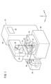
- FIG. 1 is a diagram showing the configuration of a wire electric discharge machine including a control device.
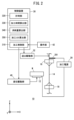
- FIG. 2 is a diagram showing the configuration and control of the control device shown in FIG.
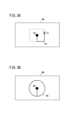
- FIG. 3A is a diagram showing an example of processing PA of the workpiece WA.
- FIG. 3B is a diagram showing an example of processing PB of the workpiece WB.
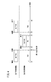
- FIG. 4 is a time-series diagram showing an example of control in which machining of the workpiece WA is interrupted and machining of the workpiece WB is performed.
- FIG. 5 is a flowchart showing control processing of the wire electric discharge machine by the control device in one embodiment.
- FIG. 6 is a time-series diagram showing an example of control in which machining of the workpiece WA is interrupted again and machining of the workpiece WC is performed.
- FIG. 7 is a flowchart showing control processing of the wire electric discharge machine by the control device in the modified example.
- FIG. 8 is a flowchart showing control processing of the wire electric discharge machine by the control
- FIG. 1 is a diagram showing the configuration of a wire electric discharge machine 10 including a control device 30.
- the wire electric discharge machine 10 applies a voltage between the gap formed by the wire electrode 14 and the workpiece to generate electric discharge, thereby performing electric discharge machining on the workpiece.
- the wire electric discharge machine 10 performs electric discharge machining while moving the wire electrode 14 relative to the workpiece along a path designated by a predetermined program. Relative movement between the wire electrode 14 and the workpiece is performed by moving the table 12 that supports the workpiece.
- the wire electric discharge machine 10 has an upper wire guide 16 , a lower wire guide 18 , an upper guide block 20 and a lower guide block 22 .
- the upper wire guide 16 supports the wire electrode 14 on the upper side (+Z direction side) of the table 12 .
- the lower wire guide 18 supports the wire electrode 14 below the table 12 (-Z direction side).
- An upper wire guide 16 is installed on the upper guide block 20 .
- a lower wire guide 18 is installed on the lower guide block 22 .
- the wire electrode 14 is supplied from the wire bobbin 24 at a predetermined speed in the feeding direction.
- the wire electrode 14 is sandwiched between pinch rollers 44 and feed rollers 46 via rollers 36 , upper wire guides 16 and lower wire guides 18 , and stored in the collection box 26 .
- the wire electric discharge machine 10 has a machining power supply 28 that supplies a voltage between poles, and a control device 30 .
- the control device 30 has a processing circuit and a memory that stores programs.
- the processing circuit executes the program, thereby functioning as the control device 30 of the present embodiment.
- the control device 30 controls machining of the workpiece by the wire electric discharge machine 10 .
- the memory includes volatile memory such as RAM and non-volatile memory such as ROM and flash memory.
- the processing circuit includes a processor such as a CPU.
- the X, Y, and Z directions shown in FIG. 1 are orthogonal to each other, and the -Z direction is the direction of gravity.
- the machining tank 34 may store machining fluid.
- the table 12, workpiece, upper wire guide 16 and upper guide block 20, lower wire guide 18 and lower guide block 22 are immersed in the machining fluid.
- a processing tank 34 is installed on a bed 38 .
- FIG. 2 is a diagram showing the configuration and control of the control device 30 shown in FIG.
- FIG. 2 shows part of the configuration of the wire electric discharge machine 10 shown in FIG.
- FIG. 2 also shows the workpiece W, the displacement drive 40, the delivery drive 32, the electrode pins 281 and the operating part 42, which are not shown in FIG.
- a workpiece W is mounted on the table 12 .
- the displacement drive unit 40 drives the table 12 to move the wire electrode 14 relative to the workpiece W in the X and Y directions.
- the displacement drive unit 40 has an X motor, a Y motor, an X drive transmission mechanism, and a Y drive transmission mechanism.
- the X motor is a motor for moving the table 12 in the X direction
- the Y motor is a motor for moving the table 12 in the Y direction.
- the X drive transmission mechanism is a mechanism for converting the rotary motion of the X motor into the linear motion of the table 12 in the X direction.
- the Y drive transmission mechanism is a mechanism for converting the rotary motion of the Y motor into the linear motion of the table 12 in the Y direction.
- Each of the drive transmission mechanism for X and the drive transmission mechanism for Y is composed of a ball screw, a nut installed on the table 12, and the like.
- Each of the X motor and the Y motor is provided with an encoder (rotational position detection sensor) for detecting the rotational position.
- a displacement drive section for driving the upper guide block 20 and the lower guide block 22 may be provided instead of the displacement drive section 40 . Further, in addition to the displacement drive section 40, a displacement drive section for driving the upper guide block 20 and the lower guide block 22 may be provided.
- the delivery drive unit 32 has a roller 36 and a delivery motor.
- the roller 36 feeds the wire electrode 14 wound around the wire bobbin 24 to the workpiece W by rotating.
- a delivery motor rotates the roller 36 .
- the delivery motor is provided with an encoder (rotational position detection sensor) for detecting the rotational position.
- the electrode pin 281 contacts the wire electrode 14 . Thereby, the machining power supply 28 can apply a voltage to the electrode pin 281 and the workpiece W, and as a result, a voltage can be applied between the electrodes.
- the control device 30 functions as a processing control unit 310, a timer unit 320, a processing time calculation unit 330, a wear amount calculation unit 340, and a processing cost calculation unit 350 by the processing circuit of the control device 30 executing the program.
- a processing control unit 310 the clock unit 320, the machining time calculation unit 330, the consumption amount calculation unit 340, and the machining cost calculation unit 350 is implemented by an ASIC, FPGA, or other integrated circuit. good too.
- the machining control unit 310 controls the delivery drive unit 32, the displacement drive unit 40, and the machining power supply 28.
- the machining control unit 310 controls the feed drive unit 32 to move the wire electrode 14 for electric discharge machining of the workpiece W from the upper wire guide 16 toward the lower wire guide 18 at a feed rate designated by the program. move.
- the machining control unit 310 controls the displacement drive unit 40 to move the wire electrode 14 relative to the workpiece W along the machining path specified by the program in the X and Y directions.
- the machining control unit 310 applies a voltage between the electrodes by controlling the machining power supply 28 .
- the timer unit 320 measures the processing time from the start or resumption of processing of the workpiece W to the interruption or end of the processing.
- the clock unit 320 may include a clock circuit that clocks the current time. In this case, the timer 320 calculates the machining time from the machining start or restart time and the machining interruption or end time. By providing a timer in the control device 30, the timer unit 320 may acquire a timer value instead of the current time, and measure the above-described machining time based on the timer value. If the machining of the workpiece W starts and ends without being interrupted, the machining time measured by the timer 320 matches the total time required for the machining.
- the machining time calculation unit 330 calculates the total machining time actually taken when the machining of the workpiece W is interrupted. For example, when machining starts, is interrupted, and then restarts and finishes, the total time is the machining time from the start to the interruption and the machining time from the restart to the end. is the sum of The machining time calculator 330 calculates the total machining time based on the machining time measured by the timer 320 .
- the consumption amount calculation unit 340 calculates the consumption amount of the consumables consumed by the processing of the processing target W based on the total time required for processing the processing target W. Depending on the type of consumable, the consumption amount depends on the total time. Examples of consumables include the electrode pins 281, the upper wire guide 16 and the lower wire guide 18, the pinch rollers 44 and the feed rollers 46, etc. described above. These wear amounts are calculated as the consumption amounts of consumables.
- the processing cost calculator 350 calculates the processing cost required for processing the object W based on the total time required for processing the object W.
- the machining cost calculator 350 may calculate the machining cost including the cost of consumables according to the amount of consumption of the consumables of the wire electric discharge machine 10 calculated by the consumption calculator 340 . Machining costs may also include consumable costs whose consumption does not depend on the total time spent in machining.
- the processing of the workpiece W may be interrupted. For example, if there is an interrupt request to the machining control unit 310 during machining of the workpiece WA, machining of another workpiece WB is started, so machining of the workpiece WA is interrupted. be.
- the operation unit 42 sends the above-described interrupt request to the processing control unit 310 according to the operator's operation.
- the operation unit 42 is composed of a touch panel, buttons, or the like.
- the machining control unit 310 controls the wire electric discharge machine 10 to interrupt the machining of the workpiece WA.
- FIG. 3A is a diagram showing an example of processing PA of the workpiece WA.
- FIG. 3B is a diagram showing an example of processing PB of the workpiece WB.
- the machining control unit 310 controls the wire electric discharge machine 10 to start machining PA on the workpiece WA from the machining start position SA of the workpiece WA.
- the operator operates the operation unit 42 because it is necessary to perform the processing PB of the object WB different from the object WA.
- the operation section 42 sends an interrupt request to the processing control section 310 . If there is an interrupt request, the machining control section 310 interrupts the machining PA.
- a machining position when the machining control unit 310 interrupts the machining PA is called a machining position IA.
- the wire electric discharge machine 10 disconnects the wire electrode 14 .
- the wire electric discharge machine 10 automatically connects the wire electrodes 14 .
- the wire electrode 14 is sandwiched between the pinch rollers 44 and the feed rollers 46 to complete the automatic wire connection.
- the wire electrode 14 is in a state where tension is applied.
- the operator operates the operation unit 42 so that the program corresponding to the machining PB is executed.
- the machining control unit 310 controls the wire electric discharge machine 10 to start the machining PB of the workpiece WB from the machining start position SB of the workpiece WB.
- the machining PB ends.
- the operator After finishing the machining PB, the operator removes the workpiece WB from the table 12 because it is necessary to restart the machining PA on the workpiece WA.
- the wire electric discharge machine 10 performs disconnection and automatic wire connection of the wire electrode 14 .
- the operator operates the operation unit 42 to restart the processing PA.
- execution of the program corresponding to machining PA is resumed.
- the machining control unit 310 controls the wire electric discharge machine 10 to restart the machining PA of the workpiece WA from the machining position IA of the workpiece WA.
- FIG. 4 is a time-series diagram showing an example of control in which machining of the workpiece WA is interrupted and machining of the workpiece WB is performed.
- the clock unit 320 acquires the current time (starting time of the machining PA) t1 from the clock circuit.
- starting time of the machining PA starting time of the machining PA
- the machining control unit 310 controls the wire electric discharge machine 10 to interrupt the machining PA.
- the clock unit 320 acquires the current time (interruption time of the machining PA) t2 from the clock circuit.
- a machining time TA1 required for the machining PA from the start to the interruption of the machining PA is obtained as the difference between the time t2 and the time t1.
- the machining control unit 310 controls the wire electric discharge machine 10 to start the machining PB.
- the timer 320 acquires the current time (the start time of the processing PB) t3 from the clock circuit.
- the clock unit 320 acquires the current time (end time of the processing PB) t4 from the clock circuit.
- the machining time TB required for the machining PB from the start to the end of the machining PB is obtained as the difference between the time t4 and the time t3.
- the total time taken for processing PB matches the processing time TB.
- the machining control unit 310 controls the wire electric discharge machine 10 to restart the machining PA. resume.
- the timer 320 acquires the current time (restart time of the machining PA) t5 from the clock circuit.
- the timer 320 acquires the current time (end time of the machining PA) t6 from the clock circuit.
- the machining time TA2 required for the machining PA from the restart to the end of the machining PA is obtained as the difference between the time t6 and the time t5.
- a total time TA required for the processing PA from the start to the end of the processing PA is obtained as the sum of the processing time TA1 and the processing time TA2.
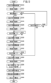
- FIG. 5 is a flowchart showing control processing of the wire electric discharge machine 10 by the control device 30 according to the present embodiment.
- the machining control unit 310 controls the wire electric discharge machine 10 to start machining PA on the workpiece WA.
- the clock unit 320 acquires the start time t1 of the processing PA from the clock circuit.
- step S514 the processing control unit 310 determines whether or not an interrupt request has been received from the operation unit 42. If the determination in step S514 is affirmative (step S514: YES), the control process proceeds to step S516, which will be described later. If a negative determination is made in step S514 (step S514: NO), the control process proceeds to step S540. In step S540, the machining control unit 310 determines whether or not execution of the program corresponding to the machining PA has ended. If the determination in step S540 is affirmative (step S540: YES), the control process proceeds to step S550, which will be described later. If a negative determination is made in step S540 (step S540: NO), the control process returns to step S514.
- the machining control unit 310 controls the wire electric discharge machine 10 to interrupt the machining PA.
- the clock unit 320 acquires the interruption time t2 of the machining PA from the clock circuit.
- the machining control unit 310 controls the wire electric discharge machine 10 to start machining PB on the workpiece WB.
- the clock unit 320 acquires the start time t3 of the processing PB from the clock circuit.
- step S524 the processing control unit 310 determines whether or not execution of the program corresponding to the processing PB has ended. If the determination in step S524 is affirmative (step S524: YES), the control process proceeds to step S526. If a negative determination is made in step S524 (step S524: NO), the control process returns to step S524. In step S526, the machining control unit 310 controls the wire electric discharge machine 10 to end the machining PB. In step S528, the clock unit 320 acquires the end time t4 of the processing PB from the clock circuit.
- the machining control unit 310 controls the wire electric discharge machine 10 to restart the machining PA.
- the clock unit 320 acquires the restart time t5 of the machining PA from the clock circuit.
- step S534 the machining control unit 310 determines whether or not execution of the program corresponding to the machining PA has ended. If the determination in step S534 is affirmative (step S534: YES), the control process proceeds to step S550. If a negative determination is made in step S534 (step S534: NO), the control process returns to step S534. In step S550, the machining control unit 310 controls the wire electric discharge machine 10 to end the machining PA. In step S552, the clock unit 320 acquires the finish time t6 of the machining PA from the clock circuit.
- step S554 the clocking unit 320 clocks the machining time TA1 required for the machining PA from the start to the interruption of the machining PA based on the times t1 and t2. Based on times t5 and t6, the timer 320 measures the machining time TA2 required for the machining PA from the restart to the end of the machining PA. The clock unit 320 clocks the total time TB required for the processing PB based on the times t3 and t4.
- step S556 the machining time calculation unit 330 calculates the total time TA required for the machining PA based on the machining times TA1 and TA2. However, if the machining PA ends without an interrupt request during the machining PA, the machining time TA1 clocked in step S554 is counted as the total time TA spent on the machining PA. In this case, the aforementioned interruption time t2 of the processing PA is treated as the end time of the processing PA. Since there is no processing PB, the total time TB spent on processing PB is not counted.
- the consumption amount calculation unit 340 calculates the consumption amount of the consumables of the wire electric discharge machine 10 consumed by machining based on the total time TA required for the machining PA.
- the wear amount of the electrode pin 281, the upper wire guide 16, the lower wire guide 18, the pinch roller 44, the feed roller 46, and the like, which are worn depending on the total time TA, is calculated as the wear amount of the consumables worn by the machining PA. be.
- the wear amount calculation unit 340 calculates the amount of wear of the consumables of the wire electric discharge machine 10 consumed by machining based on the total time TB required for the machining PB. do.
- the wear amount of the electrode pin 281, the upper wire guide 16, the lower wire guide 18, the pinch roller 44, the feed roller 46, etc., which are worn depending on the total time TB, is calculated as the wear amount of the consumables worn by the processing PB. be.
- step S560 the machining cost calculation unit 350 calculates the machining cost required for the machining PA based on the total time TA required for the machining PA and the amount of consumables consumed by the machining PA.
- the processing cost calculator 350 calculates the processing cost required for the processing PB based on the total time TB required for the processing PB and the amount of consumables consumed by the processing PB.
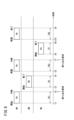
- FIG. 6 is a time series diagram showing an example of control in which the machining PA of the workpiece WA is interrupted again and the machining PC of the workpiece WC is performed.
- the processing PA is interrupted for the first time at time t2.
- machining PB is performed on the workpiece WB, and at time t5, machining PA is restarted for the first time.
- the control shown in FIG. 6 from the start time t1 of the processing PA to the first restart time t5 of the processing PA matches the control shown in FIG. Therefore, description of the control is omitted.
- the machining control unit 310 controls the wire electric discharge machine 10. to interrupt the processing PA again (second interruption).
- the clock unit 320 acquires the current time (second interruption time of the machining PA) t7 from the clock circuit.
- a machining time TA3 required for the machining PA from the first resumption of the machining PA to the second interruption is obtained as the difference between the time t7 and the time t5.
- the machining control unit 310 controls the wire electric discharge machine 10 to start the machining PC.
- the clock unit 320 acquires the current time (the start time of the machining PC) t8 from the clock circuit.
- the timer 320 acquires the current time (end time of the processing PC) t9 from the clock circuit.
- the machining time TC required for the machining PC from the start to the end of the machining PC is obtained as the difference between the time t9 and the time t8.
- the total time taken for processing PC matches the processing time TC.
- the machining control unit 310 controls the wire electric discharge machine 10 to Resuming processing PA (second resumption).
- the clock unit 320 acquires the current time (second restart time of the machining PA) t10 from the clock circuit.
- the timer 320 acquires the current time t6 from the clock circuit.
- the machining time TA2 required for the machining PA from the second restart of the machining PA to the end is obtained as the difference between the time t6 and the time t10.
- a total time TA required for the processing PA from the start to the end of the processing PA is obtained as the sum of the processing time TA1, the processing time TA2, and the processing time TA3.
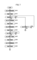
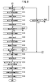
- FIG. 7 and 8 are flowcharts showing control processing of the wire electric discharge machine 10 by the control device 30 in this modification.
- the reference numerals assigned to each step of the control processing shown in FIG. 7 match the reference numerals assigned to each step of the control processing shown in FIG. 5, indicating that the same processing is executed. . Therefore, description of the processing from steps S510 to S532 and the processing of step S540 in FIG. 7 will be omitted.
- step S814 the control process proceeds to step S814, and when the process of step S540 in FIG. 7 is completed, the control process proceeds to step S550.
- step S ⁇ b>814 the processing control unit 310 determines whether or not an interrupt request has been received from the operation unit 42 . If the determination in step S814 is affirmative (step S814: YES), the control process proceeds to step S816, which will be described later. If a negative determination is made in step S814 (step S814: NO), the control process proceeds to step S840.
- step S840 the machining control unit 310 determines whether execution of the program corresponding to the machining PA has ended. If the determination in step S840 is affirmative (step S840: YES), the control process proceeds to step S550. If a negative determination is made in step S840 (step S840: NO), the control process returns to step S814.
- the machining control unit 310 controls the wire electric discharge machine 10 to interrupt the machining PA for the second time.
- the timer 320 acquires the second interruption time t7 of the machining PA from the clock circuit.
- the machining control unit 310 controls the wire electric discharge machine 10 to start machining PC for the workpiece WC.
- the clock unit 320 acquires the start time t8 of the machining PC from the clock circuit.
- step S824 the processing control unit 310 determines whether or not the execution of the program corresponding to the processing PC has ended. If the determination in step S824 is affirmative (step S824: YES), the control process proceeds to step S826. If a negative determination is made in step S824 (step S824: NO), the control process returns to step S824. In step S826, the machining control unit 310 controls the wire electric discharge machine 10 to terminate the machining PC. In step S828, the clock unit 320 acquires the end time t9 of the processing PC from the clock circuit.
- the machining control unit 310 controls the wire electric discharge machine 10 to restart the machining PA for the second time.
- the clock unit 320 acquires the second restart time t10 of the processing PA from the clock circuit.
- step S832 in FIG. 8 When the process of step S832 in FIG. 8 is completed, the control process proceeds to step S534. Since the processing from step S534 to step S552 has been described using FIG. 5, the description of these processing will be omitted.
- step S854 is performed instead of step S554 performed in the control process shown in FIG.
- the clock unit 320 counts the machining time TA1 from the start of the machining PA to the first interruption of the machining PA based on the times t1 and t2. Based on times t10 and t6, the timer 320 measures the machining time TA2 required for the machining PA from the second resumption to the end of the machining PA. The timer 320 measures the machining time TA3 required for the machining PA from the first resumption of the machining PA to the second interruption, based on the times t5 and t7.
- the clock unit 320 clocks the total time TB required for the processing PB based on the times t3 and t4.
- the clock unit 320 clocks the total time TC required for the processing PC based on the times t8 and t9.
- step S556 the machining time calculator 330 calculates the total time TA required for the machining PA based on the machining times TA1, TA2 and TA3. It should be noted that when the machining PA is completed without any interrupt request during the machining PA, the machining time TA1 timed in step S854 is counted as the total time TA required for the machining PA. In this case, the above-described first interruption time t2 of the processing PA is treated as the end time of the processing PA. Since there is no processing PB and PC, the total time TB spent on processing PB and the total time TC spent on processing PC are not counted.
- the total time TA required for the machining PA is calculated based on the machining times TA1 and TA3 timed in step S854. be done.
- the above-described second interruption time t7 of the processing PA is treated as the end time of the processing PA. Since there is no processing PC, the total time TC spent on processing PC is not counted.
- the consumption calculation unit 340 determines the amount of wire electric discharge machine 10 consumed by the machining PA, PB, and PC based on the total times TA, TB, and TC required for the machining PA, PB, and PC, respectively. Calculate the consumption of consumables.
- the processing cost calculation unit 350 calculates the respective processing costs required for processing PA and PB, as described at step S560 in FIG. Further, the processing cost calculation unit 350 calculates the processing cost required for the processing PC based on the total time TC required for the processing PC and the amount of consumables consumed by the processing PC. When the process of step S560 is completed, this control process ends.
- a control device (30) that controls a wire electric discharge machine (10) controls the wire electric discharge machine to perform a first machining (PA) on a first workpiece (WA), When there is an interrupt request during the first machining, the wire electric discharge machine is controlled to interrupt the first machining, and a second machining object different from the first machining object ( WB), and a processing control unit (310) for performing the second processing (PB) on the WB) and restarting the first processing after the second processing is completed;
- the first time (TA1) required for the first machining until the interruption (t2) of the above, and the first machining from the restart (t5) of the first machining to the end (t6) of the first machining A timing unit (320) that measures a second time (TA2), and a machining time calculator that calculates a first total time (TA) required for the first machining using the first time and the second time. a part (330);
- the clocking unit may clock a second total time (TB) required for the second machining from the start (t3) of the second machining to the end (t4) of the second machining. . This gives the total time taken for interrupt processing.
- the machining control unit controls the wire electric discharge machine to interrupt the first machining, and restores the first machining target.
- the section counts the time taken for the first processing from the first restart of the first processing to the second interruption (t7) as a third time (TA3), and the second time of the first processing.
- the time taken for the first machining from the restart (t10) to the end of the first machining is counted as the second time, and the machining time calculator measures the first time, the second time, and the second time.
- Three hours may be used to calculate the first total time taken for the first processing.
- the timing unit may time a third total time (TC) required for the third machining from the start (t8) of the third machining to the end (t9) of the third machining. . This gives the total time spent on another interrupt process.
- TC total time
- the control device that controls the wire electric discharge machine may further include a wear amount calculator (340) that calculates the wear amount of consumables that are worn out by machining based on the total time. As a result, when machining is interrupted by interrupt machining, the consumption amount of consumables of the wire electric discharge machine used for machining before interruption and machining after resuming is obtained.
- a wear amount calculator (340) that calculates the wear amount of consumables that are worn out by machining based on the total time.
- the control device that controls the wire electric discharge machine may further include a cost calculator (350) that calculates a machining cost based on the total time.
- a cost calculator 350 that calculates a machining cost based on the total time.
- a control method for controlling a wire electric discharge machine (10) includes controlling the wire electric discharge machine to perform first machining (PA) on a first workpiece (WA), When there is an interrupt request during machining, the wire electric discharge machine is controlled to interrupt the first machining, and a second machining object (WB) different from the first machining object is processed. After the second machining (PB) is completed, the first machining is restarted, machining control is performed, and the first machining is interrupted (t2) from the start of the first machining (t1) and a second time (TA2 ), and the first total time (TA) required for the first processing is calculated using the first time and the second time (S556).
- a control method for controlling a wire electric discharge machine (10) includes controlling the wire electric discharge machine to perform first machining (PA) on a first workpiece (WA), When there is an interrupt request during machining, the wire electric discharge machine is controlled to interrupt the first machining, and a second machining object (WB) different from the first machining object is processed. After the
- the timing is the second total time (TB) taken for the second machining from the start (t3) of the second machining to the end (t4) of the second machining.
- performing the machining control includes controlling the wire electric discharge machine to interrupt the first machining when there is an interrupt request again after restarting the first machining, performing a third machining (PC) on a third workpiece (WC) different from the first workpiece and the second workpiece, and performing the first machining after the third machining is completed; and counting the time includes counting the time taken for the first processing from the first restart of the first processing to the second interruption (t7) as a third time (TA3). and clocking the time taken for the first processing from the second restart (t10) of the first processing to the end of the first processing as the second time, and the calculating includes:
- the method may include calculating the first total time taken for the first processing using the first time, the second time and the third time.
- the timing is a third total time (TC) taken for the third machining from the start (t8) of the third machining to the end (t9) of the third machining.
- TC total time
- the control method may calculate (S558) a consumption amount of consumables consumed by processing based on the total time. As a result, when machining is interrupted by interrupt machining, the consumption amount of consumables of the wire electric discharge machine used for machining before interruption and machining after resuming is obtained.
- the control method may calculate a processing cost based on the total time (S560). As a result, when machining is interrupted by interrupt machining, the machining cost required for machining before interruption and machining after resuming, and the machining cost required for interrupt machining can be obtained.
Landscapes
- Engineering & Computer Science (AREA)
- Chemical & Material Sciences (AREA)
- Chemical Kinetics & Catalysis (AREA)
- Electrochemistry (AREA)
- Mechanical Engineering (AREA)
- Automation & Control Theory (AREA)
- Physics & Mathematics (AREA)
- Geometry (AREA)
- Human Computer Interaction (AREA)
- Manufacturing & Machinery (AREA)
- General Physics & Mathematics (AREA)
- Electrical Discharge Machining, Electrochemical Machining, And Combined Machining (AREA)
- Electrostatic Charge, Transfer And Separation In Electrography (AREA)
Abstract
Description
上述した一実施の形態は、以下のように変形されることとしてもよい。
上記実施の形態および変形例から把握しうる発明について、以下に記載する。
14…ワイヤ電極 16…上ワイヤガイド
18…下ワイヤガイド 20…上ガイドブロック
22…下ガイドブロック 24…ワイヤボビン
26…回収箱 28…加工電源
30…制御装置 32…送出駆動部
34…加工槽 36…ローラ
38…ベッド 40…変位駆動部
42…操作部 44…ピンチローラ
46…フィードローラ 281…電極ピン
310…加工制御部 320…計時部
330…加工時間算出部 340…消耗量算出部
350…加工コスト算出部
Claims (12)
- ワイヤ放電加工機(10)を制御する制御装置(30)であって、
前記ワイヤ放電加工機を制御して、第1の加工対象物(WA)への第1加工(PA)を行い、前記第1加工の最中に割り込み要求があった場合は、前記ワイヤ放電加工機を制御して前記第1加工を中断し、前記第1の加工対象物とは異なる第2の加工対象物(WB)への第2加工(PB)を行い、前記第2加工が終了した後に前記第1加工を再開させる加工制御部(310)と、
前記第1加工の開始(t1)から前記第1加工の中断(t2)までの前記第1加工にかかった第1時間(TA1)と、前記第1加工の再開(t5)から前記第1加工の終了(t6)までの前記第1加工にかかった第2時間(TA2)とを計時する計時部(320)と、
前記第1時間および前記第2時間を用いて前記第1加工にかかった第1の総時間(TA)を算出する加工時間算出部(330)と、
を備える、ワイヤ放電加工機を制御する制御装置。 - 請求項1に記載のワイヤ放電加工機を制御する制御装置であって、
前記計時部は、前記第2加工の開始(t3)から前記第2加工の終了(t4)までの前記第2加工にかかった第2の総時間(TB)を計時する、ワイヤ放電加工機を制御する制御装置。 - 請求項1または2に記載のワイヤ放電加工機を制御する制御装置であって、
前記加工制御部は、前記第1加工を再開させた後に再び割り込み要求があった場合は、前記ワイヤ放電加工機を制御して前記第1加工を中断し、前記第1の加工対象物および前記第2の加工対象物とは異なる第3の加工対象物(WC)への第3加工(PC)を行い、前記第3加工が終了した後に前記第1加工を再開させ、
前記計時部は、前記第1加工の1回目の再開から2回目の中断(t7)までに前記第1加工にかかった時間を第3時間(TA3)として計時するとともに、前記第1加工の2回目の再開(t10)から前記第1加工の前記終了までに前記第1加工にかかった時間を前記第2時間として計時し、
前記加工時間算出部は、前記第1時間、前記第2時間および前記第3時間を用いて前記第1加工にかかった前記第1の総時間を算出する、ワイヤ放電加工機を制御する制御装置。 - 請求項3に記載のワイヤ放電加工機を制御する制御装置であって、
前記計時部は、前記第3加工の開始(t8)から前記第3加工の終了(t9)までの前記第3加工にかかった第3の総時間(TC)を計時する、ワイヤ放電加工機を制御する制御装置。 - 請求項1~4のいずれか1項に記載のワイヤ放電加工機を制御する制御装置であって、
前記総時間に基づいて、加工によって消耗する消耗品の消耗量を算出する消耗量算出部(340)をさらに備える、ワイヤ放電加工機を制御する制御装置。 - 請求項1~5のいずれか1項に記載のワイヤ放電加工機を制御する制御装置であって、
前記総時間に基づいて、加工コストを算出するコスト算出部(350)をさらに備える、ワイヤ放電加工機を制御する制御装置。 - ワイヤ放電加工機(10)を制御する制御方法であって、
前記ワイヤ放電加工機を制御して、第1の加工対象物(WA)への第1加工(PA)を行い、前記第1加工の最中に割り込み要求があった場合は、前記ワイヤ放電加工機を制御して前記第1加工を中断し、前記第1の加工対象物とは異なる第2の加工対象物(WB)への第2加工(PB)を行い、前記第2加工が終了した後に前記第1加工を再開させる、加工制御を行い、
前記第1加工の開始(t1)から前記第1加工の中断(t2)までの前記第1加工にかかった第1時間(TA1)と、前記第1加工の再開(t5)から前記第1加工の終了(t6)までの前記第1加工にかかった第2時間(TA2)とを計時し、
前記第1時間および前記第2時間を用いて前記第1加工にかかった第1の総時間(TA)を算出する(S556)、
ワイヤ放電加工機を制御する制御方法。 - 請求項7に記載のワイヤ放電加工機を制御する制御方法であって、
前記計時することは、前記第2加工の開始(t3)から前記第2加工の終了(t4)までの前記第2加工にかかった第2の総時間(TB)を計時することを含む、ワイヤ放電加工機を制御する制御方法。 - 請求項7または8に記載のワイヤ放電加工機を制御する制御方法であって、
前記加工制御を行うことは、前記第1加工を再開させた後に再び割り込み要求があった場合、前記ワイヤ放電加工機を制御して前記第1加工を中断し、前記第1の加工対象物および前記第2の加工対象物とは異なる第3の加工対象物(WC)への第3加工(PC)を行い、前記第3加工が終了した後に前記第1加工を再開させることを含み、
前記計時することは、前記第1加工の1回目の再開から2回目の中断(t7)までに前記第1加工にかかった時間を第3時間(TA3)として計時するとともに、前記第1加工の2回目の再開(t10)から前記第1加工の前記終了までに前記第1加工にかかった時間を前記第2時間として計時することを含み、
前記算出することは、前記第1時間、前記第2時間および前記第3時間を用いて前記第1加工にかかった前記第1の総時間を算出することを含む、ワイヤ放電加工機を制御する制御方法。 - 請求項9に記載のワイヤ放電加工機を制御する制御方法であって、
前記計時することは、前記第3加工の開始(t8)から前記第3加工の終了(t9)までの前記第3加工にかかった第3の総時間(TC)を計時することを含む、ワイヤ放電加工機を制御する制御方法。 - 請求項7~10のいずれか1項に記載のワイヤ放電加工機を制御する制御方法であって、さらに、
前記総時間に基づいて、加工によって消耗する消耗品の消耗量を算出する(S558)、ワイヤ放電加工機を制御する制御方法。 - 請求項7~11のいずれか1項に記載のワイヤ放電加工機を制御する制御方法であって、さらに、
前記総時間に基づいて、加工コストを算出する(S560)、ワイヤ放電加工機を制御する制御方法。
Priority Applications (6)
| Application Number | Priority Date | Filing Date | Title |
|---|---|---|---|
| CN202180100728.XA CN117651621A (zh) | 2021-07-30 | 2021-07-30 | 控制线放电加工机的控制装置以及控制方法 |
| EP21951937.8A EP4378612A4 (en) | 2021-07-30 | 2021-07-30 | CONTROL DEVICE AND CONTROL METHOD FOR CONTROLLING A WIRED ELECTRICAL DISCHARGE MACHINE |
| JP2021563225A JP7121206B1 (ja) | 2021-07-30 | 2021-07-30 | ワイヤ放電加工機を制御する制御装置および制御方法 |
| PCT/JP2021/028473 WO2023007738A1 (ja) | 2021-07-30 | 2021-07-30 | ワイヤ放電加工機を制御する制御装置および制御方法 |
| US18/580,082 US20250091146A1 (en) | 2021-07-30 | 2021-07-30 | Control device and control method for controlling wire electrical discharge machine |
| TW111128237A TWI900786B (zh) | 2021-07-30 | 2022-07-28 | 控制金屬線放電加工機之控制裝置及控制方法 |
Applications Claiming Priority (1)
| Application Number | Priority Date | Filing Date | Title |
|---|---|---|---|
| PCT/JP2021/028473 WO2023007738A1 (ja) | 2021-07-30 | 2021-07-30 | ワイヤ放電加工機を制御する制御装置および制御方法 |
Publications (1)
| Publication Number | Publication Date |
|---|---|
| WO2023007738A1 true WO2023007738A1 (ja) | 2023-02-02 |
Family
ID=82850927
Family Applications (1)
| Application Number | Title | Priority Date | Filing Date |
|---|---|---|---|
| PCT/JP2021/028473 Ceased WO2023007738A1 (ja) | 2021-07-30 | 2021-07-30 | ワイヤ放電加工機を制御する制御装置および制御方法 |
Country Status (6)
| Country | Link |
|---|---|
| US (1) | US20250091146A1 (ja) |
| EP (1) | EP4378612A4 (ja) |
| JP (1) | JP7121206B1 (ja) |
| CN (1) | CN117651621A (ja) |
| TW (1) | TWI900786B (ja) |
| WO (1) | WO2023007738A1 (ja) |
Citations (4)
| Publication number | Priority date | Publication date | Assignee | Title |
|---|---|---|---|---|
| JPH02131821A (ja) * | 1988-11-04 | 1990-05-21 | Fanuc Ltd | 状態表示を行うワイヤ放電加工装置 |
| JPH03277444A (ja) * | 1990-03-23 | 1991-12-09 | Amada Washino Co Ltd | Nc加工機における運転制御装置 |
| JP2008027261A (ja) | 2006-07-24 | 2008-02-07 | Sodick Co Ltd | 数値制御工作機械および割込み加工方法 |
| JP2012113522A (ja) * | 2010-11-25 | 2012-06-14 | Amada Co Ltd | エネルギー消費量収集装置及びその方法 |
Family Cites Families (11)
| Publication number | Priority date | Publication date | Assignee | Title |
|---|---|---|---|---|
| JPH07178622A (ja) * | 1993-12-22 | 1995-07-18 | Fanuc Ltd | ワイヤカット放電加工機のワイヤモニタ装置 |
| AT404074B (de) * | 1994-11-10 | 1998-08-25 | Kuerzl Hans Dr | Verfahren und vorrichtung zur feststellung von erzeugnisspezifischen werten für aufwendungen, abfälle und emissionen bei gleichzeitiger herstellung unterschiedlicher erzeugnisse |
| JPH11212617A (ja) * | 1998-01-21 | 1999-08-06 | Fanuc Ltd | 複数の加工プログラムの制御装置 |
| ITRN20000043A1 (it) * | 2000-10-26 | 2002-04-26 | Scm Group Spa | Macchina utensile per la lavorazione del legno con sistema computazionale integrato |
| JP2005056272A (ja) * | 2003-08-06 | 2005-03-03 | Toyota Industries Corp | 作業時間把握システムおよび作業指示作成システム |
| JP2006305689A (ja) * | 2005-04-28 | 2006-11-09 | Makino Milling Mach Co Ltd | 加工コスト計算機能を有するワイヤ放電加工機 |
| CN101468415B (zh) * | 2007-12-25 | 2013-03-27 | 通用电气公司 | 加工控制系统 |
| WO2015011833A1 (ja) * | 2013-07-26 | 2015-01-29 | 三菱電機株式会社 | ワイヤ放電加工装置 |
| JP6235531B2 (ja) * | 2014-08-11 | 2017-11-22 | ファナック株式会社 | 任意の退避位置から放電状態で移動し中断位置に復帰する機能を有するワイヤ放電加工機 |
| JP6346216B2 (ja) * | 2016-04-01 | 2018-06-20 | ファナック株式会社 | ワイヤ放電加工機及びワイヤ放電加工方法 |
| CN206010076U (zh) * | 2016-08-15 | 2017-03-15 | 苏州奥比特精密注塑有限公司 | 电火花加工机床 |
-
2021
- 2021-07-30 WO PCT/JP2021/028473 patent/WO2023007738A1/ja not_active Ceased
- 2021-07-30 JP JP2021563225A patent/JP7121206B1/ja active Active
- 2021-07-30 EP EP21951937.8A patent/EP4378612A4/en active Pending
- 2021-07-30 CN CN202180100728.XA patent/CN117651621A/zh active Pending
- 2021-07-30 US US18/580,082 patent/US20250091146A1/en active Pending
-
2022
- 2022-07-28 TW TW111128237A patent/TWI900786B/zh active
Patent Citations (4)
| Publication number | Priority date | Publication date | Assignee | Title |
|---|---|---|---|---|
| JPH02131821A (ja) * | 1988-11-04 | 1990-05-21 | Fanuc Ltd | 状態表示を行うワイヤ放電加工装置 |
| JPH03277444A (ja) * | 1990-03-23 | 1991-12-09 | Amada Washino Co Ltd | Nc加工機における運転制御装置 |
| JP2008027261A (ja) | 2006-07-24 | 2008-02-07 | Sodick Co Ltd | 数値制御工作機械および割込み加工方法 |
| JP2012113522A (ja) * | 2010-11-25 | 2012-06-14 | Amada Co Ltd | エネルギー消費量収集装置及びその方法 |
Non-Patent Citations (1)
| Title |
|---|
| See also references of EP4378612A4 |
Also Published As
| Publication number | Publication date |
|---|---|
| JP7121206B1 (ja) | 2022-08-17 |
| EP4378612A4 (en) | 2026-03-25 |
| US20250091146A1 (en) | 2025-03-20 |
| TW202304621A (zh) | 2023-02-01 |
| JPWO2023007738A1 (ja) | 2023-02-02 |
| TWI900786B (zh) | 2025-10-11 |
| EP4378612A1 (en) | 2024-06-05 |
| CN117651621A (zh) | 2024-03-05 |
Similar Documents
| Publication | Publication Date | Title |
|---|---|---|
| JP5037941B2 (ja) | ワイヤ放電加工装置およびワイヤ放電加工方法 | |
| CN104487196B (zh) | 线电极放电加工装置 | |
| JP6017522B2 (ja) | ワイヤ交換機能を有するワイヤ放電加工機用制御装置 | |
| CN103252545B (zh) | 进行变形消除加工的电火花线切割机 | |
| JP3566988B2 (ja) | ワイヤ放電加工方法 | |
| KR102206137B1 (ko) | 와이어 방전 가공기 | |
| JP7121206B1 (ja) | ワイヤ放電加工機を制御する制御装置および制御方法 | |
| CN107297553B (zh) | 线放电加工装置 | |
| JP7074938B1 (ja) | ワイヤ放電加工機を制御する制御装置および制御方法 | |
| WO2005072900A1 (ja) | 放電加工装置及び放電加工方法 | |
| JP2017035744A (ja) | 自動結線時にワイヤ電極のたわみを検出するワイヤ放電加工機 | |
| JP5702180B2 (ja) | 電動移動体の充電装置 | |
| CN116490313A (zh) | 线放电加工机以及线放电加工机的控制方法 | |
| JP3888805B2 (ja) | 放電加工機のジャンプ制御方法および装置 | |
| TWI907554B (zh) | 金屬線放電加工機及金屬線放電加工機之控制方法 | |
| JP7010872B2 (ja) | ワイヤ放電加工機および端面位置決定方法 | |
| JP3902713B2 (ja) | 放電加工機及び放電加工機のジャンプ制御方法 | |
| JP2007326167A (ja) | ワイヤソー | |
| JP7216257B1 (ja) | ワイヤ放電加工機の制御装置および表示方法 | |
| JP2004136410A (ja) | 放電加工装置 | |
| TW202310957A (zh) | 金屬線放電加工機之控制裝置及控制方法 | |
| JP5056907B2 (ja) | 放電加工装置および放電加工方法 | |
| JP2976223B2 (ja) | 加工機適応制御装置 | |
| JPH0138615B2 (ja) | ||
| JPH071244A (ja) | ワイヤカット放電加工装置 |
Legal Events
| Date | Code | Title | Description |
|---|---|---|---|
| ENP | Entry into the national phase |
Ref document number: 2021563225 Country of ref document: JP Kind code of ref document: A |
|
| 121 | Ep: the epo has been informed by wipo that ep was designated in this application |
Ref document number: 21951937 Country of ref document: EP Kind code of ref document: A1 |
|
| WWE | Wipo information: entry into national phase |
Ref document number: 18580082 Country of ref document: US |
|
| WWE | Wipo information: entry into national phase |
Ref document number: 202180100728.X Country of ref document: CN |
|
| WWE | Wipo information: entry into national phase |
Ref document number: 2021951937 Country of ref document: EP |
|
| NENP | Non-entry into the national phase |
Ref country code: DE |
|
| ENP | Entry into the national phase |
Ref document number: 2021951937 Country of ref document: EP Effective date: 20240229 |
|
| WWP | Wipo information: published in national office |
Ref document number: 18580082 Country of ref document: US |