WO2023007762A1 - Rétracteur de ceinture, sac utilisant un rétracteur de ceinture et casque - Google Patents
Rétracteur de ceinture, sac utilisant un rétracteur de ceinture et casque Download PDFInfo
- Publication number
- WO2023007762A1 WO2023007762A1 PCT/JP2021/045720 JP2021045720W WO2023007762A1 WO 2023007762 A1 WO2023007762 A1 WO 2023007762A1 JP 2021045720 W JP2021045720 W JP 2021045720W WO 2023007762 A1 WO2023007762 A1 WO 2023007762A1
- Authority
- WO
- WIPO (PCT)
- Prior art keywords
- belt
- belt retractor
- strap
- engaging
- outer member
- Prior art date
- Legal status (The legal status is an assumption and is not a legal conclusion. Google has not performed a legal analysis and makes no representation as to the accuracy of the status listed.)
- Ceased
Links
Images





Classifications
-
- A—HUMAN NECESSITIES
- A45—HAND OR TRAVELLING ARTICLES
- A45C—PURSES; LUGGAGE; HAND CARRIED BAGS
- A45C13/00—Details; Accessories
- A45C13/30—Straps; Bands
-
- B—PERFORMING OPERATIONS; TRANSPORTING
- B65—CONVEYING; PACKING; STORING; HANDLING THIN OR FILAMENTARY MATERIAL
- B65H—HANDLING THIN OR FILAMENTARY MATERIAL, e.g. SHEETS, WEBS, CABLES
- B65H75/00—Storing webs, tapes, or filamentary material, e.g. on reels
- B65H75/02—Cores, formers, supports, or holders for coiled, wound, or folded material, e.g. reels, spindles, bobbins, cop tubes, cans, mandrels or chucks
- B65H75/34—Cores, formers, supports, or holders for coiled, wound, or folded material, e.g. reels, spindles, bobbins, cop tubes, cans, mandrels or chucks specially adapted or mounted for storing and repeatedly paying-out and re-storing lengths of material provided for particular purposes, e.g. anchored hoses, power cables
- B65H75/38—Cores, formers, supports, or holders for coiled, wound, or folded material, e.g. reels, spindles, bobbins, cop tubes, cans, mandrels or chucks specially adapted or mounted for storing and repeatedly paying-out and re-storing lengths of material provided for particular purposes, e.g. anchored hoses, power cables involving the use of a core or former internal to, and supporting, a stored package of material
- B65H75/44—Constructional details
- B65H75/4418—Arrangements for stopping winding or unwinding; Arrangements for releasing the stop means
- B65H75/4428—Arrangements for stopping winding or unwinding; Arrangements for releasing the stop means acting on the reel or on a reel blocking mechanism
- B65H75/4431—Manual stop or release button
-
- B—PERFORMING OPERATIONS; TRANSPORTING
- B65—CONVEYING; PACKING; STORING; HANDLING THIN OR FILAMENTARY MATERIAL
- B65H—HANDLING THIN OR FILAMENTARY MATERIAL, e.g. SHEETS, WEBS, CABLES
- B65H75/00—Storing webs, tapes, or filamentary material, e.g. on reels
- B65H75/02—Cores, formers, supports, or holders for coiled, wound, or folded material, e.g. reels, spindles, bobbins, cop tubes, cans, mandrels or chucks
- B65H75/34—Cores, formers, supports, or holders for coiled, wound, or folded material, e.g. reels, spindles, bobbins, cop tubes, cans, mandrels or chucks specially adapted or mounted for storing and repeatedly paying-out and re-storing lengths of material provided for particular purposes, e.g. anchored hoses, power cables
- B65H75/38—Cores, formers, supports, or holders for coiled, wound, or folded material, e.g. reels, spindles, bobbins, cop tubes, cans, mandrels or chucks specially adapted or mounted for storing and repeatedly paying-out and re-storing lengths of material provided for particular purposes, e.g. anchored hoses, power cables involving the use of a core or former internal to, and supporting, a stored package of material
- B65H75/44—Constructional details
- B65H75/4449—Arrangements or adaptations to avoid movable contacts or rotary couplings, e.g. by the use of an expansion chamber for a lenght of the cord or hose
-
- B—PERFORMING OPERATIONS; TRANSPORTING
- B65—CONVEYING; PACKING; STORING; HANDLING THIN OR FILAMENTARY MATERIAL
- B65H—HANDLING THIN OR FILAMENTARY MATERIAL, e.g. SHEETS, WEBS, CABLES
- B65H75/00—Storing webs, tapes, or filamentary material, e.g. on reels
- B65H75/02—Cores, formers, supports, or holders for coiled, wound, or folded material, e.g. reels, spindles, bobbins, cop tubes, cans, mandrels or chucks
- B65H75/34—Cores, formers, supports, or holders for coiled, wound, or folded material, e.g. reels, spindles, bobbins, cop tubes, cans, mandrels or chucks specially adapted or mounted for storing and repeatedly paying-out and re-storing lengths of material provided for particular purposes, e.g. anchored hoses, power cables
- B65H75/38—Cores, formers, supports, or holders for coiled, wound, or folded material, e.g. reels, spindles, bobbins, cop tubes, cans, mandrels or chucks specially adapted or mounted for storing and repeatedly paying-out and re-storing lengths of material provided for particular purposes, e.g. anchored hoses, power cables involving the use of a core or former internal to, and supporting, a stored package of material
- B65H75/44—Constructional details
- B65H75/4457—Arrangements of the frame or housing
- B65H75/446—Arrangements of the frame or housing for releasably or permanently attaching the frame to a wall, on a floor or on a post or the like
-
- B—PERFORMING OPERATIONS; TRANSPORTING
- B65—CONVEYING; PACKING; STORING; HANDLING THIN OR FILAMENTARY MATERIAL
- B65H—HANDLING THIN OR FILAMENTARY MATERIAL, e.g. SHEETS, WEBS, CABLES
- B65H2701/00—Handled material; Storage means
- B65H2701/30—Handled filamentary material
- B65H2701/37—Tapes
- B65H2701/375—Strapping tapes
Definitions
- the present invention relates to a retractor that winds up a strap belt and a bag and helmet using the retractor.
- a bag such as a bag has a bag part for containing small items and a strap belt part for hanging this bag part by hand, shoulder, arm, or the like.
- many shoulder bags with a belt over one shoulder and backpacks with a belt over both shoulders are provided with so-called knobs for adjusting the length of the strap belt according to the physique.
- the belt becomes a hindrance, and when the bag is placed on the rack of the train or on the floor, there are many problems where the protruding belt part unexpectedly gets caught.
- Patent Document 1 discloses a leisure bag that is provided with a belt that is convenient for carrying and that can store the belt compactly.
- Patent Document 1 it is difficult to apply the leisure bag technology of Patent Document 1 to ordinary bags such as shoulder bags and backpacks.
- the present invention is intended to solve the above-mentioned problems, and an object of the present invention is to realize a bag and a retractor for the strap belt that can accommodate the strap belt.
- the belt retractor of the present invention includes an outer member through which a strap belt can be inserted, a core portion rotatably provided inside the outer member, and a belt winding portion in the core portion. and an elastic member provided between the core and the outer member at a position offset in the axial direction, the core having an insertion portion through which the strap belt is inserted, and the insertion portion inserting the belt.
- the strap belt is retracted by rotating the core part with respect to the outer member according to the bias of the elastic member in a state where the insertion part grips the strap belt. It is wrapped around the portion and stored between the core portion and the outer member to compactly accommodate the strap belt of the bag.
- the core portion can be designed thin and compact.
- a belt retractor can be configured for
- the elastic member is a mainspring wound so as to radially overlap around the same rotation axis as the core.
- the size in the rotation axis direction can also be kept small.
- the outer member or the core has a wall provided outside the outer circumference of the mainspring at a constant distance from the rotating shaft, and the wall prevents the mainspring from being touched from the outside. As a result, it is possible to prevent the mainspring from being touched from the axial direction.
- the core portion has a tubular member and a pin member provided inside the tubular member and having the insertion portion, and the pin member and the tubular member are engaged with each other. It has an engaging portion that can be joined together, and is provided so as to be rotatable with respect to each other in a state in which the engagement at the engaging portion is released. Accordingly, by rotating the pin member with respect to the cylindrical member in a state in which the engagement at the engaging portion is released, the strap belt is wound around the pin member and stored between the pin member and the cylindrical member, By engaging the engaging portion in this state, the strap belt can be fixed in the retracted state, that is, the length of the strap belt can be adjusted.
- the engaging portion includes an engaging convex portion provided on the core portion and an engaging concave portion provided on the tubular member.
- the cylindrical member and the pin member are fixed to each other by engaging with the engaging recess.
- the tubular member further has a notch through which the engaging projection passes, so that the engaging projection passes through the notch and enters the tubular member.
- the inner end of the mainspring be engaged with the outer member and the outer end of the mainspring be engaged with the cylindrical member.
- the tubular member is biased against the outer member, and the strap belt can be wound up by the tubular member.
- the inner end of the mainspring may be engaged with the pin member, and the outer end of the mainspring may be engaged with the outer member.
- the extension length of the strap belt can be adjusted by the power of the mainspring.
- the pressing portion is provided by a cut formed in a part of the outer member, and has an elastic portion and a protrusion. Thereby, the pressing portion can be provided without adding a new member.
- said pin member rotatably engages said outer member. Thereby, it is possible to prevent the pin member from coming off from the outer member.
- the cylindrical member and the outer member have engaging portions that can be engaged with each other, and that they are provided so as to be rotatable with respect to each other in a state in which the engagement at the engaging portions is released. Thereby, it is possible to prevent the pin member from coming off from the outer member.
- the core part and the outer member have an engaging part that can be engaged with each other, and when the engagement at the engaging part is released, they are rotatable with each other, and when they are engaged, they are integrated. is desirable. Rotation can be controlled by this engaging portion.
- the engaging portion between the core portion and the outer member engages with the pressure due to the elastic deformation of the outer member, and the engagement is released against the pressure, so that the core portion is engaged with the outer member. It is desirable to wind up the strap belt by rotating with respect to.
- the strap belt can be wound up by easily releasing the engagement from the outside.
- the outer member has an arm portion made of an elastic material, and the core portion is rotatably engaged with one end of the arm portion, and the engaging portion is provided at the other end of the arm portion. It is desirable that the engagement of the engaging portion is released by applying pressure between the two ends, so that the core can be rotated.
- the bag of the present invention has backpack straps, and the belt retractor is provided on the backpack straps.
- the bag of the present invention has a shoulder strap, and the belt retractor is provided on the shoulder strap.
- the shoulder strap has a shoulder pad in the center in the length direction, and the belt retractor is provided in the center in the length direction of both sides sandwiching the shoulder pad. This allows for maximum storage of the shoulder strap.
- the helmet of the present invention has a chin strap, and the belt retractor is provided on the chin strap.
- FIG. 2 is an exploded perspective view of the belt retractor of FIG. 1 viewed from another angle; It is (A) AA sectional drawing, (B) BB sectional drawing, (C) CC sectional drawing (D) top view which shows the state which assembled the belt retractor of FIG. It is (a) a top view, (b) a left side view, (c) a front view, (d) a right side view, and (e) a rear view showing a state in which the belt retractor of FIG. 3 is attached to a bag. It is an exploded perspective view of a belt retractor of a second embodiment. Fig.
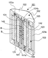
- FIG. 6 is a cross-sectional perspective view of the assembled belt retractor of Fig. 5; It is an exploded perspective view of a belt retractor of a third embodiment.
- FIG. 6 is an exploded perspective view of the belt retractor of FIG. 5 as seen from another angle; It is an exploded perspective view of a belt retractor of a fourth embodiment.
- FIG. 10 is an exploded perspective view of the belt retractor of FIG. 9 viewed from another angle; It is the (a) side view, (b) top view, (c) front view which shows the state which mounted
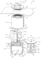
- FIG. 1 is an exploded perspective view of the belt retractor of the first embodiment of the invention.
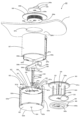
- FIG. 2 is an exploded perspective view of the belt retractor of FIG. 1 viewed from another angle.
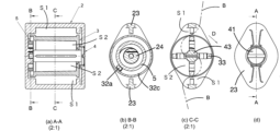
- 3 is (A) a cross-sectional view taken along line A-A, (B) a cross-sectional view taken along line B-B, (C) a cross-sectional view taken along line C-C, and (D) a plan view showing the state in which the belt retractor of FIG. 1 is assembled.
- the belt retractor 1 of the first embodiment includes an outer member 2, a cylindrical member 3 and a pin member 4 as core portions rotatably provided inside the outer member 2, A cylindrical member 3 as a core and a spring 5 as an elastic member biased to rotate the pin member 4 with respect to the outer member 2.
- the pin member 4 as a part of the core rotates the belt B. It has a slit 43a as an insertion portion through which it is inserted, and the cylindrical member 3 and the pin member 4 as core portions rotate relative to the outer member 2 while gripping the belt B according to the bias of the spring 5 as an elastic member.
- the belt B winds around the tubular member 3 which is a part of the core and is housed in the space S1 between the tubular member 3 and the outer member 2 .
- the spring 5 is stored at a position axially displaced from the pillar 33 which is the belt winding portion of the core.
- the pin member 4 and the cylindrical member 3 have an engaging convex portion 43b and an engaging concave portion 37 as engaging portions that can be engaged with each other, and the pin member 4 is disengaged from the engaging portions. is rotatably provided inside the tubular member 3 .
- the belt B is wound around the pin member 4, and the belt B is wound around the pin member 4, as shown in FIG. will be accommodated in the space S2.
- the winding length of the belt B around the pin member 4 is determined. In this way, it is possible to adjust the extension length of the belt of the bag.
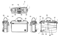
- the bag 6 of the embodiment of the present invention includes a main body 60, backpack straps 61 for carrying the main body as a backpack, shoulder straps 62 for hanging the main body on the shoulder as a shoulder bag, A pair of handles 63 for gripping the main body like a handbag, a carry strap 64 for attaching the main body to a carrier with wheels, and an opening 65 for loading and unloading luggage into and from the main body, which is opened and closed by a zipper. and at least.
- the backpack strap 61 is constructed by stitching a shoulder pad 61a and a strap belt 61b to each other at one end, and sewn to the main body 60 at the other end.
- a belt retractor 1 is mounted near the center in the longitudinal direction of the strap belt 61b. Since the belt retractor 1 installed as described above winds and stores the strap belt 61b, as shown in FIG.
- the integrated state prevents the backpack strap 61 from sagging even when the bag 6 is held like a handbag using the handle 63 or used as a shoulder bag using the shoulder strap 62.
- the length adjustment mechanism is built into the belt retractor 1, so the ends of the remaining backpack straps do not hang down, and when used as a backpack, The backpack straps 61 are stretched to the set length.
- the backpack strap 6 has a chest strap 66 between the pads 61a. One end (lower end in the drawing) of the chest strap 66 is connected to the pad 61a by a shaft and the other end is connected by a strong magnet. It is also magnetically attached to one pad 61a.
- the shoulder strap 62 is constructed by sewing a shoulder pad 62a to one end of each of a pair of strap belts 62b at the middle in the length direction of the shoulder strap 62, and the pair of strap belts 62b are attached to the main body at the other end. 60 is sewn on.
- a belt retractor 1 is attached near the center in the length direction of each of the pair of strap belts 62b. Since the belt retractor 1 installed as described above winds and stores the strap belt 62b, as shown in FIG.
- the shoulder strap 62 does not hang down even when the bag 6 is held like a handbag using the handle 63 or used as a backpack using the backpack strap 61.
- the length adjustment mechanism is built in the belt retractor 1, so that the so-called hook is not required, and metal fittings for making the shoulder strap removable are also unnecessary.
- the shoulder pad 62a can be sewn to the center of the shoulder strap, so that the shoulder pad can be removed from the center, which tends to occur with conventional shoulder straps. You can avoid problems such as shifting and turning inside out.
- the backpack strap 61 extends to the set length. As a matter of course, it is desirable to set the length adjustment mechanism of the belt retractor 1 to the same extent on the left and right sides.
- the belt retractor 1 includes an outer member 2, a cylindrical member 3 and a pin member 4 as core portions rotatably provided inside the outer member 2, and a cylindrical member 3 as a core portion. and a spring 5 as an elastic member biased to rotate the pin member 4 with respect to the outer member 2 .
- Parts other than the mainspring 5 are made of resin, but can also be made of metal.
- the outer member 2 includes an open surface 21 and a closed surface 22, which are a pair of substantially rhombic surfaces provided perpendicular to the rotation axis of the pin member 4, and an opening surface 21 and a closed surface 22 between the ends of the open surface 21 and the closed surface 22.
- a pair of pillars 23 extending in a columnar shape perpendicular to the opening surface 21; It has a pair of slits 26, a pair of elastic portions 27 defined by these in line symmetry, and a pair of protrusions 28 provided at the ends of these elastic portions.
- the open surface 21 is substantially diamond-shaped as described above, with an opening 29 formed in the center.
- the pin member 4 is inserted into this opening 29, Since the head 41 is a hole into which the head 41 is rotatably fitted, it has a circular shape with an inner diameter slightly larger than the head 41 of the pin member 4 .
- a part of the arc of this circle is constituted by a pair of protrusions 28 .
- a pair of elastic portions 27 formed in a bridge shape by two pairs of slits 26 provided in the longitudinal direction of the open surface 21 have elasticity derived from a resin material, and projecting portions 28 are provided at their tips. there is The elastic portion 27 and the projecting portion 28 constitute a pressing portion.
- the projecting portion 28 is a member for pressing the cylindrical member 3 toward the closing surface 22 and protrudes toward the closing surface 22 .
- the side surface of the protrusion 28 is a tapered surface 28a.
- the projection 28 is pushed outward by the elasticity of the elastic portion 27 , so that the cylindrical member 3 can smoothly enter the outer member 2 .
- the protruding portion 28 is provided on the peripheral edge of the opening 29, the friction surface between the cylindrical member 3 and the outer member 2 is provided radially inward as much as possible and has a small area, thereby improving the rotational performance of the cylindrical member 3.
- the projecting portion 28 urges the tubular member 3 toward the closing surface 22 when the tubular member 3 is assembled in the outer member 2 .
- the projecting portion 28 escapes to the outside.
- a pair of block portions 21a are provided.
- the block portion 21a is a portion for restricting the movement of the tubular member 3 toward the opening surface 21 while ensuring a necessary clearance when the tubular member 3 is incorporated into the outer member 2. It protrudes to the side of the slit 26 on the side opposite to the side to be incorporated into the outer member 2 . If the block part 21a is not provided and the material is flexible enough to allow the cylindrical member 3 to be incorporated into the outer member 2 even if the open surface 21 is provided inside, the block part 21a is not provided. may
- a pair of pillars 23 are provided perpendicularly to the open surface 21 and the closed surface 22 so as to connect their vertices, and a pair of limiting blocks 23a and 23b are provided inside the connecting portions to each. These restriction blocks 23a and 23b restrict the belt B from being shifted toward the open surface 21 side or the closed surface 22 side when the belt B is wound. Note that the number of pillars is not limited to one pair, and may be two pairs depending on the strength of the material.
- a bearing portion 24 which is a circular protrusion for bearing the pin member 4 is provided in the center of the closing surface 22 .
- a circular bearing recess 24a is provided in the center of the bearing portion 24 for receiving the tip projection 42 of the pin member 4, and the inner end 5b of the mainspring 5 is placed at a position slightly displaced from the center of the bearing portion 24.
- a slit 24b is provided for receiving.
- the mainspring 5 has an L-shaped inner end 5b and a U-shaped outer end 5a, and has at least about four turns.
- the cylindrical member 3 has a first surface 31 and a second surface 32 which are a pair of circular surfaces corresponding to the above-described open surface 21 and closed surface 22, and these surfaces are perpendicular to the belt surface. They are mutually supported by four pillar members 33 as winding portions.
- a first hole 35 and a second hole 34 for receiving the shaft portion 43 of the pin member 4 are bored in the first surface 31 and the second surface 32, respectively, and their inner diameters correspond to the shaft portion 43 of the pin member 4. It is slightly larger than the outer diameter of the portion 43 .
- a cross-shaped hole is provided around the second hole 34 toward the column member 33, but this is a device for removing the mold, and functionally, the second hole 34 is a circular hole. you can
- a notch 36 for allowing the engagement projection 43b of the pin member 4 to pass is formed continuously with the first hole 35 so as to penetrate from the front and back.
- An engagement recess 37 for engaging the engagement protrusion 43 a of the pin member 4 is provided at a position continuous with the first hole 35 on the inner side surface of the first surface 31 .
- the engaging recess 37 has a depth reaching about half of the thickness from the inner side surface of the first surface 31 .
- a mainspring receiving projection 32a is provided that protrudes vertically from the second surface 32 at a portion near the circumference. This is a projection for receiving the outer end 5a of the mainspring 5.
- the cylindrical member 3 is rotationally biased against the outer member 2 via the mainspring 5 .
- an arc-shaped projection 32b is provided around the second hole 34 on the outer surface of the second surface 32 to prevent the spring 5 from contacting the second surface 32 as much as possible and to prevent the cylindrical member 3 and the outer member 2 from contacting each other. It plays the role of adjusting the gap between them.
- a circumferential flange 32c is provided on the outer periphery of the second surface 32 perpendicularly to the second surface 32 to prevent the user from touching the mainspring 5 by mistake.
- the pin member 4 has a flange-shaped head portion 41 provided at one end, a tip convex portion 42 provided at the other end, and a shaft portion 43 extending therebetween.
- the head 41 has a groove 41a in the center with which a slotted screwdriver or a coin can be engaged.
- the shaft portion 43 has a slit 43a as an insertion portion through which the belt B is inserted along the length direction. Further, the shaft portion 43 has a pair of engaging protrusions 43 b that protrude vertically from the vicinity of the head portion 41 , pass through the notch portion 36 and engage with the engaging recess portion 37 .
- the mainspring 5 is set on the outer member 2 with the inner end 5b inserted into the slit 24b, and the cylindrical member 3 is assembled with the outer end 5a hooked on the mainspring receiving projection 32a. is set on the outer member 2.
- the second surface 32 is opposed to the closing surface 22 so that the second hole 34 corresponds to the bearing portion 24, and then the circumferential portion of the first surface 31 presses the tapered surface 28a of the projection 28 to elastically
- the elasticity of the portion 27 is used to push the protrusion 28 outward while pushing the first surface 31 in parallel with the open surface 21 .
- the pin member 4 is inserted through the opening 29 and the first hole 35, and the tip protrusion 42 is inserted into the bearing recess 24a.
- the pin member 4 is aligned so that the engaging convex portion 43b passes through the notch portion 36.
- the cylindrical member 3 is moved toward the open surface 21 while pushing out the projecting portion 28 to the outside.
- the engaging convex portion 43b passes through the notch portion 36, and a coin or the like can be engaged with the groove 41a to rotate the pin member 4 about its axis.
- the tubular member 3 moves toward the closing surface 22, and the engagement protrusion 43b engages the engagement recess 24a.
- the pin member 4 and the cylindrical member 3 are integrated.
- the elastic portion 27 has a function of releasing the protrusion 28 to the outside when the cylindrical member 3 is incorporated into the outer member 2, and releases the engagement between the engaging convex portion 43b and the engaging concave portion 24a. Therefore, it also has the function of letting the protrusion 28 escape to the outside.
- the core part in which the pin member 4 and the tubular member 3 are integrated is axially rotated several times in the direction indicated by arrow D in FIG. 4(c), i.e., from one side of the pillar 23, pass between the pillar 23 and the pillar member 33, and then insert the strap belt into the slit 26.
- the belt is passed through the belt retractor 1 so as to pass through an S-shaped route that passes from the other side to the other side, passes between the column member 33 on the opposite side and the column portion 23 on the opposite side, and passes through to the other side.
- the core is wound in the direction opposite to arrow D in FIG. It is wound around the circumference, that is, around the column member 33 of the cylindrical member 3, and stored in the space S1.
- the strap is then sewn onto the bag. This prevents the belt retractor 1 from coming off the strap belt.
- the belt retractor 1 When the belt retractor 1 is set on the shoulder strap or backpack strap and the bag is carried on the back in this way, the strap belt is released against the bias of the mainspring 5 due to the self weight of the bag, and the strap belt is extended.
- adjusting the belt retractor 1 can limit the stretched length of the strap belt.
- the engagement protrusion 43b and the engagement recess 24a are aligned with each other with the strap belt having an appropriate length, and the pressing of the protrusion 28 by the cylindrical member 3 is released, the engagement protrusion 43b and the engagement recess are released. 24a are engaged, the pin member 4 and the cylindrical member 3 are integrated, and the strap belt accommodated in the space S2 is no longer stretched. In this manner, the stretched length of the strap belt can be appropriately adjusted.
- the extension length is adjusted in one step for each half rotation of the pin member 4, and is not a stepless adjustment. The length can be exactly the same on the left and right, and the length can be adjusted evenly on the left and right very easily and accurately compared to the conventional hook.
- the strap belt is automatically retracted so that the strap belt does not get in the way, the extension length of the strap belt can be adjusted, and the strap belt does not get in the way. It is possible to realize a bag 6 that does not have a rough end.
- the belt retractor 1 of the first embodiment is merely an example, and various modifications can be made in the form of the same effect.
- the number and shape of the pillars of the outer member and the pillars of the tubular member, the shape and position of the pressing portion can be changed as appropriate, and the engagement relationship between the pin member and the tubular member can also be reversed.
- Elastic members such as coiled springs and rubber can be used in addition to the mainspring.
- the ends of the mainspring can also be engaged with the outer member and the pin member. Furthermore, when the core is composed of a single member, even if a separate mechanism is required for adjusting the extension length, at least the strap belt can be automatically wound up to realize a bag in which the strap belt does not get in the way. can do.
- the belt retractor can also be used for musical instrument straps, seat belts, waist belts, packing belts, cables and cords.
- FIG. 1 The belt retractor 101 has many parts similar to the belt retractor 1 of the first embodiment, but mainly, the elastic structure is provided on the pin member instead of the outer member, and the tip of the pin member is bifurcated. It differs greatly in that it can be retrofitted to the strap belt by having a slit in the column portion of the outer member.
- the belt retractor 101 of the second embodiment includes an outer member 102, a cylindrical member 103 and a pin member 104 as core portions rotatably provided inside the outer member 102, and a cylindrical member 103 and a pin as core portions.
- spring 105 as a resilient member biased to rotate member 104 relative to outer member 102; Parts other than the spring 105 are made of resin, but they can also be made of metal.
- the outer member 102 has an open surface 121 and a closed surface 122, which are a pair of substantially rhombus-shaped surfaces provided perpendicular to the rotation axis of the pin member 104, and between the ends of the open surface 121 and the closed surface 122.
- An opening 129 is formed in the center of the open surface 121, and a pin member 104 provided in the center of the inner surface of the closed surface 122 is rotatably supported. and a plurality of protrusions 129a provided on the periphery of the opening 129 inside the open surface 121. As shown in FIG.
- the open surface 121 has a substantially rhombic shape as described above, and an opening 129 is formed in the center.
- the opening 129 is a hole into which the pin member 104 is inserted and the head 141 of which is rotatably fitted.
- the protrusion 129a restricts the movement of the tubular member 103 toward the open surface 121, it reduces the friction between the tubular member 103 and the outer member 102, thereby increasing the rotatability and facilitating the insertion of the tubular member 103 into the outer member 102.
- It is a member for providing a gap for squeezing, and protrudes toward the closing surface 122 .
- the cylindrical member 103 can enter the outer member 102 more smoothly.
- the material is flexible enough to allow the cylindrical member 3 to be incorporated into the outer member 2 even if the projecting portion 129a is not provided and the open surface 21 is provided on the inner side, and the friction between the cylindrical member 103 and the outer member 102 If the coefficient is sufficiently small, the protrusion 129a may not be provided.
- a pair of pillars 123 are provided perpendicular to the open surface 121 and the closed surface 122 so as to connect their respective vertexes, and a pair of limiting blocks 123a and 123b are provided inside the connecting portions to each. These restriction blocks 123a and 123b restrict the belt B from being shifted toward the open surface 121 side or the closed surface 122 side when the belt B is wound.
- an auxiliary column portion 123c is provided in parallel with the column portion 123 on one side (on the right side in the figure).
- the auxiliary column portion 123c is provided perpendicular to the open surface 121 and the closed surface 122 and in parallel with the column portion 123, but has a gap 123d in the central portion in the longitudinal direction and extends from the open surface 121.
- the auxiliary column portion 123c and the auxiliary column portion 123c extending from the closing surface 122 are not connected. Therefore, a slit 123e is formed between the column portion 123 and the auxiliary column portion 123c. If the strap belt is positioned in the slit 123e through the gap 123d, the strap belt slides in the slit 123e and does not come off. becomes possible.
- the number of pillars is not limited to one pair, and may be two pairs depending on the strength of the material.
- a bearing portion 124 which is a circular protrusion for bearing the pin member 104 is provided in the center of the closing surface 122 .
- a circular bearing protrusion 124a is provided at the center of the bearing 124 to be inserted into the tip cylindrical portion 142 of the pin member 104, and the inner end 105b of the spring 105 is received at a position passing through the center of the bearing 124.
- a slit 124b is provided for this purpose.
- the mainspring 105 has an L-shaped inner end 105b and a U-shaped outer end 105a, and has at least about four turns.
- the tubular member 103 is configured in substantially the same manner as the tubular member 3 .
- the tubular member 103 has a first surface 131 and a second surface 132, which are a pair of circular surfaces corresponding to the above-described open surface 121 and closed surface 122, and these surfaces are formed by four vertically provided They are mutually supported by column members 133 .
- a first hole 135 and a second hole 134 are formed in the center of the first surface 131 and the second surface 132 respectively for receiving the shank 143 of the pin member 104 . It is slightly larger than the outer shape of the portion 143 .
- a cross-shaped hole is provided around the second hole 134 toward the column member 133, but this is a device for removing the mold, and functionally, the second hole 134 is a circular hole. you can
- a notch portion 136 for the engaging convex portion 143a of the pin member 104 to pass through is bored continuously from the first hole 135 so as to penetrate from the front and back.
- An engagement recess 137 for engaging the engagement protrusion 143 a of the pin member 104 is provided at a position continuous with the first hole 135 on the inner side surface of the first surface 131 .
- This engaging recess 137 has a depth reaching about half of the thickness from the inner side surface of the first surface 131 .
- the outer surface of the second surface 132 is provided with a mainspring receiving projection that protrudes vertically from the second surface 132 at a portion near the circumference. ing. This is a projection for receiving the outer end 105a of the mainspring 105.
- the cylindrical member 103 is rotationally biased against the outer member 102 via the spring 105 .
- a circular projection 132 b is provided around the second hole 134 on the outer surface of the second surface 132 and serves to adjust the gap between the cylindrical member 103 and the outer member 102 .
- a circumferential flange 132c is provided on the outer periphery of the second surface 132 perpendicularly to the second surface 132 to prevent the user from touching the spring 105 by mistake.
- the pin member 104 has a collar-shaped head portion 141 provided at one end, a tip cylindrical portion 142 provided at the other end, and a shaft portion 143 extending therebetween.
- the head 141 has a groove 141a in the center with which a slotted screwdriver or a coin can be engaged.
- the shaft portion 143 has a slit 143b as an insertion portion through which the belt B is inserted along the length direction. Further, the shaft portion 143 has a pair of engaging projections 143 a that vertically protrude in the axial direction from the vicinity of the head portion 141 , pass through the notch portion 136 and engage with the engaging recess portion 37 .
- the pin member 104 is particularly different from the pin member 4 in that the tip cylindrical portion 142 is bifurcated and that the shaft portion 143 has a plurality of notches 143c provided perpendicular to the shaft.
- the tip tubular portion 142 is divided into two parts, so that the slit 143b penetrates to the tip of the pin member 104, so that the belt can be inserted from the tip side, so that the strap belt sewn on the bag can be used.
- a belt retractor 101 can be retrofitted.
- the shaft portion 143 can elastically contract in the axial direction. Therefore, it is possible to engage and release the engagement protrusion 143a and the engagement recess 137 without moving the cylindrical member 103 in the axial direction.
- the mainspring 105 is set on the outer member 1002 with the inner end 15b inserted into the slit 124b, and the cylindrical member 103 is pushed with the outer end 105a hooked on the protruding portion for receiving the mainspring.
- the outer member 2 Set on the outer member 2.
- the second surface 132 is opposed to the closing surface 122 so that the second hole 134 corresponds to the bearing portion 124, and then the circumferential portion of the first surface 131 presses the tapered surface of the protrusion 129a to form the outer member.
- the first surface 131 is pushed in parallel with the open surface 121 .
- the belt retractor 101 can be retrofitted to the strap belt sewn on the bag.
- the cylindrical member 103 is axially rotated several times against the bias of the mainspring 105 . While maintaining this state, the belt retractor 101 is applied from the side of the strap belt, and the strap belt is inserted into the slit 123e using the gap 123d.
- the engaging convex portion 143b passes through the notch portion 136 and becomes a non-engaging state, so that the pin member 4 can be axially rotated by engaging a coin or the like with the groove 141a.
- the engaging protrusion 143b releases the pressure on the head 141 at a position corresponding to the engaging recess 124a, the compression of the pin member 104 is released and the engaging protrusion 143b engages with the engaging recess 124a.
- the pin member 4 and the cylindrical member 3 are integrated. By doing so, even if the strap belt is sewn to the bag in advance, the attachment of the belt retractor 101 to the strap belt is completed.
- the tip tubular portion 142 is bifurcated.
- the presence of the auxiliary column portion 123c prevents the belt retractor 101 from hanging from the strap belt, and the belt retractor 101 can be assembled along the strap belt.
- the belt retractor 101 When the belt retractor 101 is set on the shoulder strap or backpack strap and the bag is carried on the back in this way, the strap belt is released against the urging force of the spring 105 due to the weight of the bag itself, and the strap belt is extended.
- adjusting the belt retractor 101 can limit the stretched length of the strap belt.
- the strap belt is wound around the pin member 104, that is, accommodated in the space S102 between the column member 133 and the pin member 104.
- the engaging protrusion 143b and the engaging recess 124a are aligned with each other with the strap belt having an appropriate length, and the pressure of the head 141 is released, the engaging protrusion 143b and the engaging recess 124a are engaged.
- the pin member 104 and the tubular member 103 are integrated, and the strap belt housed in the space S102 is no longer stretched. In this manner, the stretched length of the strap belt can be appropriately adjusted.
- extension length is adjusted in one step for each half rotation of the pin member 104, and is not a stepless adjustment.
- the length can be exactly the same on the left and right, and the length can be adjusted evenly on the left and right very easily and accurately compared to the conventional hook.
- the strap belt is automatically retracted so that the strap belt does not get in the way, the extension length of the strap belt can be adjusted, and the strap belt does not get in the way. It is possible to realize a bag that does not have sharp ends.
- the belt retractor 101 of the second embodiment is an example, and various modifications can be made in the form of the same effect.
- the material is not limited to resin, and metal or wood may be used, and other materials may be used for the elastic portion.
- the number and shape of the pillars of the outer member and the pillars of the tubular member, and the shape and position of the pressing portion can be appropriately changed.
- Elastic members such as coiled springs and rubber can be used in addition to the mainspring.
- the ends of the mainspring can also be engaged with the outer member and the pin member. Furthermore, when the core is composed of a single member, even if a separate mechanism is required for adjusting the extension length, at least the strap belt can be automatically wound up to realize a bag in which the strap belt does not get in the way. can do.
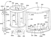
- the belt retractor 201 of the third embodiment will be explained using FIGS. 7 and 8.
- FIG. The belt retractor 201 has many parts similar to the belt retractor 1 of the first embodiment, but mainly, the pin member penetrates the outer member and has a retainer, and the inner end of the mainspring engages the pin member. However, the outer end is engaged with the outer member, and the cylindrical member is engaged with the outer member when moved against the force of the outer member.
- the belt retractor 201 of the third embodiment includes an outer member 202, a cylindrical member 203 and a pin member 204 as core portions rotatably provided inside the outer member 202, and a cylindrical member 203 and a pin as core portions.
- spring 205 as a resilient member biased to rotate member 204 relative to outer member 202; Parts other than the mainspring 205 are made of resin, but can also be made of metal.
- the outer member 202 includes an open surface 221 and a bearing surface 222, which are a pair of substantially rhombus-shaped surfaces provided perpendicular to the rotation axis of the pin member 204, and between the ends of the open surface 221 and the bearing surface 222.
- An opening 229 is formed at the center of the open surface 221, and a pin member 204 provided at the center of the inner surface of the bearing surface 222 is rotatably mounted on the bearing surface 222. and an engaging protrusion 229a provided on the periphery of the opening 229 inside the open surface 221. As shown in FIG.
- the open surface 221 has a substantially rhombic shape as described above, and an opening 229 is formed in the center.
- the opening 229 is a hole into which the pin member 204 is inserted and the head 241 of which is rotatably fitted.
- a portion of the arc of this circle is formed by a pair of protrusions 228 .
- a pair of elastic portions 227 formed in a bridge shape by two pairs of slits 226 provided in the longitudinal direction of the open surface 221 have elasticity derived from a resin material, and projecting portions 228 are provided at their tips. there is The elastic portion 227 and the projecting portion 228 constitute a pressing portion.
- the projecting portion 228 is a member for pressing the cylindrical member 203 toward the bearing surface 222 and protrudes toward the bearing surface 222 .
- the side surface of the protrusion 228 is a tapered surface 228a.
- the projection 228 is pushed outward by the elasticity of the elastic portion 227 , so that the cylindrical member 203 can smoothly enter the outer member 202 .
- the protrusion 228 is provided on the periphery of the opening 229, the friction surface between the cylindrical member 203 and the outer member 202 is made radially inward and has a small area as much as possible, thereby improving the rotation of the cylindrical member 203.
- the protrusion 229a engages with the groove 203a provided on the first surface 231 of the tubular member 203 when the tubular member 203 moves toward the opening surface 221, thereby making the tubular member 203 unrotatable with respect to the outer member 202. , and protrudes toward the bearing surface 222 .
- a pair of pillars 223 are provided perpendicular to the open surface 221 and the bearing surface 222 so as to connect their vertexes, and a pair of limiting blocks 223a and 223b are provided inside the connecting portions to each. These restricting blocks 223a and 223b restrict the belt B from deviating to the open surface 221 side or the bearing surface 222 side when the belt B is wound. Note that the number of pillars is not limited to one pair, and may be two pairs depending on the strength of the material.
- a bearing hole 224 that is a circular through hole for bearing the pin member 204 is provided in the center of the bearing surface 222 .
- the bearing hole 224 is a circular bearing through-hole into which the tip portion 242 of the pin member 204 is inserted.
- a block 222a for engaging the outer end 205a of the mainspring 205 is provided at a position near the circumference of the bearing surface 222. As shown in FIG.
- the mainspring 205 has an L-shaped inner end 205b and a U-shaped outer end 205a, and has at least about four turns.
- the cylindrical member 203 has a first surface 231 and a second surface 232, which are a pair of circular surfaces corresponding to the above-described open surface 221 and bearing surface 222, and these surfaces are formed by four vertically provided surfaces. They are mutually supported by the column members 233 .
- a first hole 235 and a second hole 234 for receiving the shank 243 of the pin member 204 are bored in the first surface 231 and the second surface 232 , respectively, and their inner diameters correspond to the shaft of the pin member 204 . It is slightly larger than the outer shape of the portion 243 .
- a cross-shaped hole 234a is provided around the second hole 234 toward the column member 233. This is a device for extracting the mold, and the front side engaging projection of the pin member 204, which will be described later. It is also for passage of the portion 243c.
- the first surface 231 has four cutouts 236 continuously connected to the first hole 235 and through which the four head-side engaging protrusions 243b and the four front-side engaging protrusions 243c of the pin member 204 pass. is perforated in a form that penetrates the front and back.
- the notch 236 also serves as an engaging recess for the head-side engaging protrusion 243b.
- the outer surface of the second surface 232 is provided with four engaging recesses 234b that are continuous with the hole 234a. This is for the front-side engagement projection 243c of the pin member 204 to engage.
- a circumferential flange 232c is provided on the outer periphery of the second surface 232 perpendicularly to the second surface 232 to prevent the user from touching the spring 205 by mistake.
- the pin member 204 includes a brim-shaped head portion 241 provided at one end, a shaft portion 243 connected thereto and extending, a tip end portion 242a provided at the other end, and a head portion connected thereto. It has a mainspring engaging portion 242b and a retainer 242c provided at the tip of the tip portion 242a.
- the pin member 204 is provided with a slit 242d passing through the axis from the tip to the mainspring engaging portion 242b via the tip 242a. This slit 242d is for receiving the inner end 205b of the mainspring 205.
- the head 241 has a groove 241a in the center with which a slotted screwdriver or a coin can be engaged.
- the shaft portion 243 has a slit 243b as an insertion portion through which the belt B is inserted along the length direction.
- This slit 243b is not limited to being linear, and may be designed to be wave-like.
- the shaft portion 243 protrudes vertically in the axial direction from the vicinity of the head portion 241, passes through the notch portion 236, and in some cases has four head-side engaging protrusions 243b that engage with the notch portion 236. have.
- the shaft portion 243 protrudes vertically in the axial direction from a position adjacent to the mainspring engaging portion 242b, passes through the notch portion 236 and the cross hole 234a, and is connected to the cross hole 234a in some cases. It has four front side engaging protrusions 243c that engage with the engaging recesses 234b.
- the mainspring engaging portion 242b is formed thinner than the main body of the shaft portion 243 and is a position around which the mainspring 205 is wound.
- the distal end portion 242 a is formed to be even thinner, and since it is a portion inserted into the bearing hole 224 , it has an inner diameter slightly smaller than the inner diameter of the bearing hole 224 .
- the stopper 242c provided at the tip is formed to be thicker than the inner diameter of the bearing hole 224 in a barbed shape, and passes through the bearing hole 224 using the flexibility generated by the slit 242d, and after the elastic deformation returns, the pin The member 204 cannot be pulled out of the bearing hole 224.
- a jig (not shown) for holding the inner end 205b of the spring 205 is inserted through the bearing hole 224 from the outside of the bearing hole 224 to hold the inner end 205b of the spring 205. . Further, with the spring 205 wound, the outer end 205a is engaged with the block 222a. In addition, it is preferable that the jig has a mechanism to be held by the bearing surface 222 . Subsequently, the tubular member 203 is fitted into the outer member 202 from the side.
- the second surface 232 is opposed to the bearing surface 222 so that the second hole 234 corresponds to the bearing hole 224, and then the tapered surface 228a of the protrusion 228 is pressed by the circumference of the first surface 231 to elastically
- the elasticity of the portion 227 is used to push the protrusion 228 outward while pushing the first surface 231 in parallel with the open surface 221 .
- the groove 203a is installed at a position corresponding to the engaging protrusion 229a.
- the pin member 204 is inserted through the opening 229 and the first hole 235, then the tip portion 242a is inserted through the bearing hole 224, and the mainspring engaging portion and the front-side engaging convex portion 243c are inserted through the second hole 234. do. Then, the stopper 242c passes through the bearing hole 224 and restores to function as a stopper. In this state, the jig is removed, and the spring 205 tries to turn the pin member 204 by its restoring force.
- the cylindrical member 203 is released. moves toward the bearing surface 222, the head-side engaging protrusion 243b engages with the notch 236, and the front-side engaging protrusion 243c engages with the engaging recess 234b. 203 are integrated.
- the elastic portion 227 has the function of releasing the protrusion 228 to the outside when the tubular member 203 is incorporated into the outer member 202, and the front-side engaging protrusion that moves the tubular member 203 toward the bearing surface 222. 243c and the head-side engaging protrusion 243b are engaged with the engaging recess 234b and the notch 236. As shown in FIG.
- the strap belt enters from one side of the column portion 223 and passes through between the column portion 223 and the column member 233 and passes from one side of the slit 226 to the other side.
- the belt is passed through the belt retractor 201 so as to pass through the gap to the other side.
- the cylindrical member 203 is pushed by the protrusion 228 and moves toward the bearing surface 222, disengages the protrusion 229a from the groove 203a, and biases the engagement spring 5.
- a core portion in which the pin member 204 and the cylindrical member 203 are integrated is wound by the outer member 202 , and the strap belt is held by the slit 226 and wound around the core portion, that is, around the column member 233 of the cylindrical member 203 . stored inside. The strap is then sewn onto the bag. This prevents the belt retractor 201 from coming off the strap belt.
- the belt retractor 201 When the belt retractor 201 is set on the shoulder strap or backpack strap and the bag is carried on the back in this way, the strap belt is released from the retraction against the bias of the spring 205 due to the weight of the bag itself, and the strap belt is extended.
- adjusting the belt retractor 201 can limit the stretched length of the strap belt.
- the pin member 204 When the bag is lifted to loosen the extension of the strap belt with the cylinder member 203 engaged with the outer member 202 and not engaged with the pin member 204, the pin member 204 is pivoted by the restoring force of the mainspring 205. As it rotates, the strap belt is wound around the pin member 204 , ie stowed in the space between the post member 233 and the pin member 204 .
- the head-side engagement protrusion 243b and the notch 236 are aligned with each other with the strap belt having an appropriate length, and the pressing of the protrusion 228 by the cylindrical member 203 is released, the head-side engagement protrusion 243b and the notch 236 are released.
- the notch 236 is engaged with the front side engaging projection 243c and the engaging recess 234b at the same time, the pin member 204 and the cylindrical member 203 are integrated, and the space between the column member 233 and the pin member 204 is integrated.
- the strap belt housed in the space is no longer stretched. In this manner, the stretched length of the strap belt can be appropriately adjusted.
- the protrusion 229a is disengaged from the groove 203a, so that the surplus strap belt is automatically wound around the column member 233.
- the extension length is adjusted in one step for each quarter rotation of the pin member 204, and is not stepless adjustment.
- the extension length of the right and left can be exactly the same, and the length can be adjusted evenly on the left and right very easily and accurately as compared with the conventional hook.
- the strap belt is automatically retracted so that the strap belt does not get in the way, the extension length of the strap belt can be adjusted, and the strap belt does not get in the way. It is possible to realize a bag that does not have sharp ends.
- the belt retractor 201 of the third embodiment is merely an example, and various modifications can be made in the form of similar effects.
- the number and shape of the pillars of the outer member and the pillars of the tubular member, the shape and position of the pressing portion can be changed as appropriate, and the engagement relationship between the pin member and the tubular member can also be reversed.
- Elastic members such as coiled springs and rubber can be used in addition to the mainspring.
- the ends of the mainspring can also be engaged with the outer member and the pin member. Furthermore, when the core is composed of a single member, even if a separate mechanism is required for adjusting the extension length, at least the strap belt can be automatically wound up to realize a bag in which the strap belt does not get in the way. can do.
- the belt retractor 201 of the third embodiment is advantageous in that the stretched length of the strap belt can be adjusted by the restoring force of the mainspring 205 instead of by manual winding. As a result, the groove 241a of the head 241 can be omitted, and the head 241 can be made smaller. Further, by providing four engaging convex portions on the head side and the tip side of the pin member 204, and by providing four engaging convex portions each, twisting of the pin member 204 is suppressed, and engagement between the pin member 204 and the cylindrical member 203 is intended. It is possible to avoid being released without being done. The extension length can be adjusted by one step for each quarter turn of the pin member 204, and unintentional pull-out of the pin member can be prevented.
- the cylindrical member 203 By engaging the cylindrical member 203 with the pin member 204 and the outer member 202, assembly of the mainspring and each member and passage of the belt strap are facilitated.
- the inner diameter of the mainspring By engaging the inner end of the mainspring with the pin member, the inner diameter of the mainspring can be reduced, the number of turns can be increased, and the outer diameter can be reduced.
- the engagement between the pin member and the outer member is not limited to the anti-loosening structure at the tip of the pin member, but the head portion may have a similar anti-loosening structure.
- FIG. The belt retractor 301 has the same parts as the belt retractor 1 of the first embodiment, but is greatly different in that it is installed inside the bag. For this reason, the belt retractor 301 has an engagement release mechanism so that it can be switched from the outside of the bag between an adjust mode for changing the belt length limit and a fix mode for fixing the belt length limit. It has a configuration.
- the belt retractor 301 of the fourth embodiment includes an outer member 302, a cylindrical member 303 and a pin member 304 as core portions rotatably provided inside the outer member 302, and a cylindrical member 303 and a pin as core portions.
- a mainspring 305 as an elastic member that biases the member 304 to rotate with respect to the outer member 302, a U-shaped member 306 that grips the cylindrical member 303 and the outer member 302 at the tips of both arms, and a U-shaped member.
- Parts other than the mainspring 305 are made of resin, but can also be made of metal.
- the outer member 302 includes an open surface 321 and a bearing surface 322, which are a pair of disk-shaped surfaces provided perpendicular to the rotation axis of the pin member 304, and a space between the ends of the open surface 321 and the bearing surface 322.
- An opening 329 is formed in the center of the open surface 321, and a pin member 304 provided in the center of the bearing surface 322 is rotatably supported by the bearing. and a bearing hole 324 for The pair of pillars 323a and 323b has recesses 323c on both sides thereof for guiding the belt through which the belt passes.
- the open surface 321 has a disk shape as described above, and an opening 329 is formed in the center.
- the opening 329 is a hole into which the pin member 304 is inserted and the head 341 of which is rotatably fitted.
- a portion of the arc of this circle is formed by a pair of protrusions 328 .
- a pair of elastic portions 327 formed in a bridge shape by two pairs of slits 326 provided in the longitudinal direction of the open surface 321 have elasticity derived from a resin material, and projecting portions 328 are provided at their tips. there is The elastic portion 327 and the projecting portion 328 constitute a pressing portion.
- the projecting portion 328 is a member for pressing the cylindrical member 303 toward the bearing surface 322 and protrudes toward the bearing surface 322 . Further, as shown in FIG. 10, the side surface of the protrusion 328 is a tapered surface 328a. The projection 328 is pushed outward by the elasticity of the elastic portion 327 , so that the tubular member 303 can smoothly enter the outer member 302 .
- a pair of pillars 323 are provided perpendicular to the open surface 321 and the bearing surface 322 . Note that the number of pillars is not limited to one pair, and may be two pairs depending on the strength of the material.
- a bearing hole 324 that is a circular through hole for bearing the pin member 304 is provided in the center of the bearing surface 322 .
- the bearing hole 324 is a circular bearing through-hole into which the tip portion 342 of the pin member 304 is inserted.
- Two pairs of blocks 322a are provided near the circumference of the bearing surface 322 for engaging the outer ends 305a of the mainspring 305 and for limiting the outer circumference of the mainspring 305.
- the mainspring 305 is a mainspring having an inner end 305b formed by bending into an L-shape and an outer end 305a formed by bending into a U-shape.
- the cylindrical member 303 has a first surface 331 and a second surface 332, which are a pair of circular surfaces corresponding to the above-described open surface 321 and bearing surface 322, and these surfaces are formed by four vertically provided surfaces. They are mutually supported by the column members 333 .
- a first hole 335 and a second hole 334 are formed in the center of the first surface 331 and the second surface 332 respectively for receiving the shaft portion 343 of the pin member 304 . It is slightly larger than the outer diameter of portion 343 .
- first surface 331 and the second surface 332 On the first surface 331 and the second surface 332, four head-side engaging protrusions 343b and four front-side engaging protrusions 343c of the pin member 304 are formed continuously with the first hole 335 and the second hole 334. Four cutouts 336a and 336b for engagement are bored through the front and back.
- the pin member 304 has a brim-shaped head portion 341 provided at one end, a shaft portion 343 connected thereto and extending therefrom, a tip end portion 342a provided at the other end thereof, and a head portion connected thereto. It has a mainspring engaging portion 342b and a retainer 342c provided at the tip of the tip portion 342a.
- the pin member 304 is provided with a slit 342d passing through the axis from the tip to the mainspring engaging portion 342b via the tip 342a. This slit 342 d is for receiving the inner end 305 b of the mainspring 305 .
- the shaft portion 343 has a slit 343a as an insertion portion through which the belt B is inserted along the length direction.
- This slit 343a is not limited to being linear, and may be designed to be wavy or the like.
- the shaft portion 343 protrudes vertically in the axial direction from the vicinity of the head portion 341, passes through the notch portion 336, and in some cases has four head-side engaging protrusions 343b that engage with the notch portion 336. have.
- the shaft portion 343 projects vertically in the axial direction from a position adjacent to the mainspring engaging portion 342b, passes through the notches 336a and 336b, and optionally has four tip ends that engage the notch portion 336b. It has an engaging projection 343c.
- the mainspring engaging portion 342b is formed to be partially thinner than the main body of the shaft portion 343, and is a position around which the mainspring 205 is wound.
- the distal end portion 342 a is formed to be even thinner, and since it is a portion inserted into the bearing hole 324 , it has an inner diameter slightly smaller than the inner diameter of the bearing hole 324 .
- the stopper 342c provided at the end is formed to be thicker than the inner diameter of the bearing hole 324, and passes through the bearing hole 324 using the flexibility generated by the slit 342d. The stop 342c is fitted into the bearing hole 324 so that the pin member 304 does not slip out of the bearing hole 324.
- the U-shaped member 306 holds the cylindrical member 303 on the side of the open surface 321 of the outer member 302 so that the engaging projections 343b and 343c of the pin member 304 are engaged with the notches 336a and 336b of the cylindrical member 303. It is a member for engaging the engagement protrusions 343b and 343c of the pin member 304 with the notches 336a and 336b of the cylindrical member 303 when releasing the engagement and releasing the holding.
- the U-shaped member 306 has a pair of arm portions 306b extending in opposing directions perpendicular to the rotation shaft 306a, and a claw portion 306c provided at the tip of the arm portion 406b.
- the tip of the claw portion is a surface facing the arm portion 306 b and has a function of gripping a flange portion 331 a provided on the circumference of the first surface 331 of the cylindrical member 303 .
- the open surface 321 of the outer member 302 has a pair of tapered portions 321a having an inclination projecting toward the U-shaped member 306 along the circumference of the outer surface.
- the pair of tapered portions 321a are rotationally symmetrical and have an inclination that gradually increases in the clockwise direction.
- the arm portion 406b of the U-shaped member 306 rises along this inclination to pull the cylindrical member 303 toward the outer member 302 side.
- the tapered portion 321a has a flat top so as not to generate a return moment when the U-shaped member 306 is rotated clockwise. Further, it has a rotation stop 321b that restricts rotation when rotated clockwise, and a rotation stop 321c that contacts the U-shaped member 306 when rotated counterclockwise.
- an engaging mechanism consisting of a concave portion 306d and a convex portion 321d is provided inside the U-shaped member 306 and on the outer periphery of the open surface 321.
- the convex portion 321d is connected to the outer periphery of the open surface 321 via a pantograph-like elastic structure.
- a rotating shaft 306a of the U-shaped member 306 has an engaging portion 306e at its tip, which is inserted through a hole 308c of the cover member 307 into an engaging hole 309a of the knob member 309 and engaged.
- the knob member 309 has a knob portion 309b, and the U-shaped member 306 can be operated by rotating this clockwise or counterclockwise. When the U-shaped member 306 rotates clockwise, it climbs up the tapered portion 321 a and pulls the cylindrical member 303 against the stress of the protrusion 328 to the open surface 321 of the outer member 302 .
- the pin member 304 does not move in the axial direction because the tip portion 342 does not come out of the bearing hole 324, and the notch portion 336, the notch portion 336b, the head-side engaging convex portion 343b, and the tip-side engaging convex portion 343c do not move in the axial direction. is disengaged.
- the pin member 304 becomes rotatable with respect to the cylindrical member 303, and the belt inserted through the slit 343a is wound around the pin member 303 by the rotational force of the spring 305, and is defined by the column member 333 of the cylindrical member 303. contained within the space.
- the U-shaped member 306 moves down the tapered portion 321a, and when the pin member 303 is rotated by slightly pulling the belt, the cylinder member 303 is moved with the pin member 303 by the force of the protrusion 328. Since they are engaged and integrated, the belt is wound around the column member 333 by the rotational force of the spring 305 . In this manner, the length of the belt is adjusted inside the column member 333 and the remaining belt is wound outside the column member 333 .
- the cover member 307 is a member that covers the outer member 302 and the U-shaped member 306 from the outside, and is open downward. Notches 307a corresponding to the column members 323a and 323b and four claws 307b engaged with four claw receiving grooves 322b of the outer member 302 are provided. It has a threaded opening 307c on the upper side, and is screwed to the male threaded portion 308a of the pressing member 308 which is inserted through the round hole of the bag fabric F and screwed. In addition, projections 307d that bite into the bag fabric F to prevent relative rotation are arranged in a circle around the screw-shaped opening 307c.
- the pressing member 308 has a recessed portion 308b at its center, in which the knob 309 is received.
- a jig (not shown) for holding the inner end 305b of the spring 305 is inserted through the bearing hole 324 from the outside of the bearing hole 324 to hold the inner end 305b of the spring 305. . Further, with the spring 305 wound, the outer end 305a is engaged with the block 322a. In addition, it is preferable that the jig has a mechanism to be held by the bearing surface 322 . If the inner edge 305b is naturally centered, no jig may be required. Subsequently, the cylindrical member 303 is fitted into the outer member 302 from the side.
- the second surface 332 is opposed to the bearing surface 322 so that the second hole 334 corresponds to the bearing hole 324, and then the tapered surface 328a of the protrusion 328 is pressed by the circumference of the first surface 331 to elastically
- the elasticity of the portion 327 is used to push the protrusion 328 outward while pushing the first surface 331 in parallel with the open surface 321 .
- the pin member 304 is inserted through the opening 329 and the first hole 335, then the tip portion 342a is inserted through the bearing hole 324, and the mainspring engaging portion and the front-side engaging convex portion 343c are inserted through the second hole 334. do.
- the retainer 342c passes through the bearing hole 324 and restores to function as a retainer.
- the jig is removed, and the spring 305 tries to turn the pin member 304 by its restoring force.
- the cylinder member 303 moves toward the bearing surface 322, the head-side engaging protrusion 343b engages with the engaging recess 336a, and the front-side engaging protrusion 343c engages with the engaging recess 334b.
- the tubular member 303 is integrated. In this state, the strap belt is moved from one side of the pillar member 323a through the entry pillar member 333 to the other side of the slit 326 and to the other side or one side of the pillar member 323b. pass through.
- the U-shaped member 306 is placed outside the head portions 341 of the outer member 302 and the pin member 303 while sliding it so that the claw portion 306c at the tip thereof is positioned under the flange portion 331a.
- the cover member 307 is put on the column member 323b so that the notch 307a corresponds to the column member 323b.
- the strap belt passes through one of the slits formed between the cover member 307 and the left and right concave portions 323c of the column member.
- the screw-shaped opening 307c is aligned with the hole in the fabric F, and the pressing member 308 is attached by the male screw portion 308a so as to sandwich the fabric.
- the knob member 309 is attached to the rotating shaft 306a to complete the assembly.
- the knob member 309 When the assembly is completed in this way, the knob member 309 is normally rotated counterclockwise, and the pin member 304 and the tubular member 303 are integrated, so that the strap belt can be secured. coils around the post 333 and is wound up by the bias of the mainspring 305 or extended against it. In this way, the strap belt can be wound up.
- the knob member 309 when it is desired to adjust the length of the strap belt, the knob member 309 is turned clockwise while the strap belt is stretched and not wound around the column portion 333 . Then, the pin member 304 becomes rotatable with respect to the cylindrical member 303, and the belt inserted through the slit 343a is wound around the pin member 303 by the rotational force of the mainspring 305 when the strap belt is not pulled.
- the extension length of the strap belt is limited.
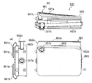
- FIG. 11A and 11B are schematic trihedral views of a bag equipped with this belt retractor 301, FIG. 11(a) being a side view, (b) being a top view, and (c) being a front view.
- the bag 600 of the embodiment of the present invention comprises a main body 660, a backpack strap 661 for carrying the main body as a backpack, and a shoulder strap 662 for carrying the main body on the shoulder as a shoulder bag, and the main body is gripped like a handbag. and an opening 665 for loading and unloading luggage into and out of the main body, which is opened and closed by a zipper.
- the backpack strap 661 is constructed by sewing a shoulder pad 661a and a strap belt 661b together at one end, and the shoulder pad 661a is sewn to the main body 660 at the other end.
- the first belt retractor 301a is attached to the side cloth of the main body 660 of the bag 600, that is, to the center of the bottom surface when the bag 600 is used as a backpack.
- a circular hole is made in the fabric at this portion, and the belt retractor 301a is applied from the inside of the bag, and the pressing member 308 is screwed to the cover member 307 from the outside, whereby the belt is retracted.
- a retractor 301 a is attached to the bag 600 .
- the strap belt 661b passes through the belt retractor 301a and both ends are connected to the left and right shoulder pads 661a. Since the belt retractor 301 installed as described above winds and stores the strap belt 661b, as shown in FIG.
- the backpack straps 661 are integrated with the main body 660, so that the backpack straps 661 can be held even when the handle 663 is used to hold the bag 600 like a handbag, or when the shoulder straps 662 are used to use it as a shoulder bag. It never hangs down.
- the length adjustment mechanism is built into the belt retractor 301a, so the ends of the remaining backpack straps do not hang down, and when used as a backpack, The backpack straps 661 extend to the length as set.
- the adjustment mode is entered by turning the knob member 309 clockwise while carrying the bag 600 as a backpack.
- the bag 600 is adjusted up and down to the desired length, and by turning the knob member 309 counterclockwise, the fix mode is activated. For example, it will extend, but it will not exceed the length determined earlier.
- the shoulder strap 662 is constructed by sewing a shoulder pad 662a to both ends of a pair of strap belts 662b in the middle in the length direction of the shoulder strap 662, and the strap belt 662b is inside the second belt retractor 301b. is passing through
- the belt retractor 301b is arranged at the corner of the fabric on the front of the bag 600, and is fixed by sandwiching the fabric around the circular hole, like the belt retractor 301a. Since the belt retractor 601 installed in this manner retracts and stores the strap belt 662b, as shown in FIG. In this state, the shoulder strap 662 does not hang down even when the handle 663 is used to hold the bag 600 like a handbag or the backpack strap 661 is used as a backpack.
- the length adjustment mechanism is built into the belt retractor 301b, so that a so-called hook is not required, and metal fittings for making the shoulder strap removable are also unnecessary.
- the shoulder pad 662a can be sewn in the center of the shoulder strap, so that the shoulder pad can be removed from the center, which tends to occur with conventional shoulder straps. You can avoid problems such as shifting and turning inside out.
- the shoulder bag strap 662 When used as a shoulder bag, the shoulder bag strap 662 extends to the set length.
- the belt retractor 301 When the belt retractor 301 is set on the shoulder strap and the backpack strap and the bag is carried on the back in this way, the strap belt is released against the bias of the mainspring 305 due to the self weight of the bag, and the strap belt is extended.
- adjusting the belt retractor 301 can limit the stretched length of the strap belt.
- the strap belt is automatically retracted so that the strap belt does not get in the way, the extension length of the strap belt can be adjusted, and the strap belt does not get in the way. It is possible to realize a bag that does not get in the way because the belt retractor itself is built into the bag without any sharp ends sticking out.
- the belt retractor 301 of the fourth embodiment is merely an example, and various modifications can be made in the form of the same effect.
- the number and shape of the pillars of the outer member and the pillars of the tubular member, the shape and position of the pressing portion can be changed as appropriate, and the engagement relationship between the pin member and the tubular member can also be reversed.
- Elastic members such as coiled springs and rubber can be used in addition to the mainspring. The ends of the mainspring can also be engaged with the outer member and the pin member.
- the retractor functions even without the cover member, and for switching between the adjustment mode and the fix mode, a structure other than the structure of the U-shaped member and the knob may be used to slide the cylindrical member.
- the core is composed of a single member, even if a separate mechanism is required for adjusting the extension length, at least the strap belt can be automatically wound up to realize a bag that does not interfere with the strap belt. can do.
- the belt retractor of the present invention is not limited to bags, and can be used for various straps such as musical instrument straps, waist pouch straps, and seat belts.
- FIG. 12 is a perspective view of a fifth embodiment belt retractor of the present invention for use with a helmet belt.
- a bicycle helmet is worn by engaging connectors provided at the ends of left and right belts under the chin with the helmet worn on the head, and the length is adjusted by a so-called flip-panel.
- the skin of a child, especially a child may get caught in the connector, and the helmet cannot be attached without using both hands. There is also the trouble of having to perform mounting and length adjustment separately.
- the belt retractor 401 of the fifth embodiment includes an arm member 402 as an outer member, a mainspring storage cap 403 and a control cap 404 as a pair of cap members, and a core portion rotatably provided inside the outer member. and a spring 406 as an elastic member biased so as to rotate the pin member 405 as a core with respect to the mainspring storage cap member 403 .
- Parts other than the spring 405 are made of resin, but they can also be made of metal.
- the arm member 402 has a U-shaped arm portion 421 , and flat mainspring housing cap receiving portions 422 and control cap receiving portions 423 provided opposite to both ends of the arm portion 421 .
- the arm part 421 has flexibility derived from its shape and material, and is selected to have a rectangular or oval cross-sectional structure.
- the mainspring storage cap receiving portion 422 and the control cap receiving portion 423 are substantially rectangular flat surfaces corresponding to the mainspring storage cap 403 and the control cap 404, and each have a pair of engaging claws 424. As shown in FIG.
- the tip of the engaging claw 424 is provided with a hook 424a for retaining.
- the mainspring housing cap member 403 has a bearing surface 431 which is a substantially rectangular surface provided perpendicular to the rotation axis of the pin member 405, and the four sides of the bearing surface 431 extending outward parallel to the rotation axis. and a wall surface 432 .
- a bearing hole 434 that is a circular through hole for bearing the pin member 405 is provided in the center of the bearing surface 431 .
- the bearing hole 434 is a circular bearing through-hole into which the tip portion 452 of the pin member 405 is inserted.
- Slits 434 a are provided in contact with the upper and lower sides of the bearing hole 434 . This is a slit that promotes flexible deformation to facilitate reception of the tip portion 452 of the pin member 405 .
- a pair of right and left engaging holes 432 a are provided between the bearing surface 431 and the wall surface 432 and engage with the engaging claws 424 of the arm member 402 .
- a block for engaging the outer end 406a of the mainspring 406 is provided on the axially outer side of the bearing surface 431 at a position close to the outer edge.
- the mainspring 406 is a mainspring having an inner end 406b formed by bending into an L-shape and an outer end 406a formed by bending into a U-shape.
- the control cap 404 has a bearing surface 441, which is a substantially rectangular surface provided perpendicular to the rotation axis of the pin member 405, and wall surfaces 442 extending outward parallel to the rotation axis from the four sides of the bearing surface 441. and
- a bearing hole 444 which is a circular through hole for bearing the pin member 405 , is provided in the center of the bearing surface 441 .
- An engagement recess 443 is provided.
- a pair of right and left engaging holes 442 a are provided between the bearing surface 441 and the wall surface 442 and engage with the engaging claws 424 of the arm member 402 .
- a rotation space 444 in which the engagement protrusion 453 rotates without being hindered is formed outside the engagement recess 443 in the axial direction.
- the pin member 405 has a spline-shaped head portion 454 provided at one end, a shaft portion 455 extending in connection therewith, and a tip portion 452 provided at the other end.
- the tip portion 452 has a slit 452a on the tip side and is flexible to hold the inner end 406 of the mainspring 405 and facilitate insertion into the bearing hole 434.
- the tip of the distal end portion 452 has a tapered shape with a chamfer 452 b so that it can be easily inserted into the bearing hole 434 . Since the bearing contact portion 452c that contacts the bearing is formed to have a small radius, the tip portion 452 is prevented from coming out after being inserted into the bearing hole 434.
- the shaft portion 455 has a slit 455a as an insertion portion through which the belt is inserted along the length direction.
- the slits 455a are not limited to being linear, and may be designed to be wave-like.
- the head 454 has six engaging protrusions 453 protruding perpendicularly to the axial direction.
- a method of assembling the belt retractor 401 configured as above will be explained.
- the pin member 405 is inserted through the bearing hole 444 of the control cap 404 , and then the tip portion 452 of the pin member 405 is inserted into the bearing hole 434 of the mainspring housing cap 403 .
- the bearing surface 431 is flexibly deformed by the slit 434a, and the tip portion 452 is flexibly deformed by the slit 452a, so that it can be inserted.
- the inner end 406b and the outer end 406a of the spring 406 are stretched between the slit 452a and the block provided on the bearing surface 431. As shown in FIG.
- control cap 404 and the mainspring storage cap 403 are inserted into the engagement holes 442a and 432a with the engaging claws 424 and pushed in until the calyx 424a comes out. 422 and control cap receiver 423 .
- the engagement projection 453 is engaged with the engagement recess 443 .
- pin member 405 does not rotate.
- the pin member 405 is pushed by the mainspring storing cap 403 and further enters the control cap 404, thereby is disengaged from the engaging recess 443 , and the spline head 454 of the pin member 405 moves into the rotation space 444 . Since the head 454 is then rotatable, the pin member 405 can be turned against the bias of the mainspring 406 .
- the pin member 405 When the pin member 405 is fully rotated, the pressure on the mainspring storage cap receiving portion 422 and the control cap receiving portion 423 is released, and the engaging convex portion 453 and the engaging concave portion 443 engage again, and the pin member 405 rotates. It will be in a state of not doing. Then, the chin strap belt of the helmet is passed through the slit 455a. The belt is continuously connected from the right side of the helmet to the left side via the belt retractor 401 . In this state, when the mainspring housing cap receiving portion 422 and the control cap receiving portion 423 are pressed from the outside so as to be pinched, the pin member 405 rotates according to the bias of the mainspring 406, and the belt is wound.
- the belt can be retracted by simply pinching the belt retractor 401, and the length of the belt of the helmet can be appropriately adjusted. Just by releasing the belt retractor 401, the length of the belt is fixed, and even if the helmet is pulled, the belt will not stretch, and there will be no pain when it bites into the chin or the skin will be caught. If the arm member 402 is positioned outside the belt, the arm member 402 can be prevented from hitting the face.
- the belt retractor of the present invention can be used for various purposes.
- the object to be wound is not only a flat belt, but also a string can be used.
- the belt retractor 401 of the fifth embodiment can also be used for bags, and the belt retractors of other embodiments can also be applied to helmets.
- the belt retractor 401 of the fifth embodiment releases the engagement between the pin member and the outer member by pressing, conversely, the engagement may be released under normal conditions and engaged by pressing. . Latches can also be used to allow rotation of the core in one direction only.
Landscapes
- Purses, Travelling Bags, Baskets, Or Suitcases (AREA)
- Helmets And Other Head Coverings (AREA)
- Portable Outdoor Equipment (AREA)
- Buckles (AREA)
- Emergency Lowering Means (AREA)
Abstract
Priority Applications (3)
| Application Number | Priority Date | Filing Date | Title |
|---|---|---|---|
| US18/292,260 US12667174B2 (en) | 2021-07-26 | 2021-12-10 | Belt retractor, bag using belt retractor, and helmet |
| CN202180100979.8A CN117715563A (zh) | 2021-07-26 | 2021-12-10 | 带卷收器及使用该带卷收器的包和头盔 |
| JP2022520603A JP7157406B1 (ja) | 2021-07-26 | 2021-12-10 | ベルトリトラクター及びこれを用いたバッグ並びにヘルメット |
Applications Claiming Priority (2)
| Application Number | Priority Date | Filing Date | Title |
|---|---|---|---|
| JP2021-121152 | 2021-07-26 | ||
| JP2021121152 | 2021-07-26 |
Publications (1)
| Publication Number | Publication Date |
|---|---|
| WO2023007762A1 true WO2023007762A1 (fr) | 2023-02-02 |
Family
ID=85086557
Family Applications (1)
| Application Number | Title | Priority Date | Filing Date |
|---|---|---|---|
| PCT/JP2021/045720 Ceased WO2023007762A1 (fr) | 2021-07-26 | 2021-12-10 | Rétracteur de ceinture, sac utilisant un rétracteur de ceinture et casque |
Country Status (4)
| Country | Link |
|---|---|
| US (1) | US12667174B2 (fr) |
| JP (2) | JP7157406B1 (fr) |
| CN (1) | CN117715563A (fr) |
| WO (1) | WO2023007762A1 (fr) |
Citations (5)
| Publication number | Priority date | Publication date | Assignee | Title |
|---|---|---|---|---|
| JPS5915507A (ja) * | 1982-04-15 | 1984-01-26 | レパプレス・アクチエンゲゼルシヤフト | 顎ベルト調節装置を有する防護ヘルメツト |
| JPH0466919U (fr) * | 1990-10-24 | 1992-06-15 | ||
| JP2002544093A (ja) * | 1999-04-28 | 2002-12-24 | スペキュラティブ プロダクト デザイン インコーポレーテッド | 巻き取り式コード装置 |
| JP2008043719A (ja) * | 2006-07-18 | 2008-02-28 | Susumu Nakatani | 付勢巻取り装置 |
| CN207322961U (zh) * | 2017-08-17 | 2018-05-08 | 王进添 | 伸缩带控制装置 |
Family Cites Families (17)
| Publication number | Priority date | Publication date | Assignee | Title |
|---|---|---|---|---|
| US3198300A (en) * | 1963-05-31 | 1965-08-03 | George K Tuttle | Handle having a retractable strap |
| IT217863Z2 (it) * | 1989-03-03 | 1992-02-11 | Gazzola Giovanni Andrea | Maniglia per colli a mano, convertibile in tracolla |
| AU644819B2 (en) * | 1989-11-21 | 1993-12-23 | Major Co. Ltd. | Device for lodging a suspending strap for a portable object |
| FR2744111B1 (fr) * | 1996-01-30 | 1999-01-22 | Tech D Accessoires Specialises | Enrouleur de sangle |
| US6053381A (en) * | 1997-10-14 | 2000-04-25 | Fahl; Scott R. | Retractable shoulder strap backpack |
| US5897039A (en) * | 1998-04-22 | 1999-04-27 | Swenke; J. Kevin | Retractable strap |
| US6536697B2 (en) * | 2001-07-10 | 2003-03-25 | Chin-Yuan Tsan | Structure of automatic suspender reeling device |
| FR2827487B1 (fr) * | 2001-07-20 | 2004-05-21 | Salomon Sa | Article de bagagerie a dispositif de retenue externe |
| US8123092B2 (en) * | 2002-03-06 | 2012-02-28 | United States Luggage, L.P. | Retractable shoulder strap for carrying case |
| JP2006043233A (ja) | 2004-08-06 | 2006-02-16 | Shimano Inc | レジャー用バッグ |
| US7942360B2 (en) * | 2006-01-25 | 2011-05-17 | Winston Products Llc | Retractable tow strap |
| EP2378911B1 (fr) * | 2008-11-21 | 2014-05-21 | Boa Technology, Inc. | Système de laçage a enrouleur |
| EP2592964B1 (fr) * | 2010-07-12 | 2016-08-31 | Unternehmensgruppe Hiebl GmbH | Dispositif support avec enrouleur de courroie |
| US9908454B1 (en) * | 2014-03-28 | 2018-03-06 | Terry Waters, Jr. | Tie-down strap coiling device |
| US9730507B2 (en) * | 2015-06-08 | 2017-08-15 | Eric Wendler | Retractable shoulder strap for portable objects |
| US10233052B2 (en) * | 2016-06-23 | 2019-03-19 | William F. Joyner | Retractable strap |
| US12233294B2 (en) * | 2020-09-25 | 2025-02-25 | Werner Co. | Harness adjustment device |
-
2021
- 2021-12-10 WO PCT/JP2021/045720 patent/WO2023007762A1/fr not_active Ceased
- 2021-12-10 US US18/292,260 patent/US12667174B2/en active Active
- 2021-12-10 JP JP2022520603A patent/JP7157406B1/ja active Active
- 2021-12-10 CN CN202180100979.8A patent/CN117715563A/zh active Pending
-
2022
- 2022-07-22 JP JP2022117603A patent/JP2023017738A/ja active Pending
Patent Citations (5)
| Publication number | Priority date | Publication date | Assignee | Title |
|---|---|---|---|---|
| JPS5915507A (ja) * | 1982-04-15 | 1984-01-26 | レパプレス・アクチエンゲゼルシヤフト | 顎ベルト調節装置を有する防護ヘルメツト |
| JPH0466919U (fr) * | 1990-10-24 | 1992-06-15 | ||
| JP2002544093A (ja) * | 1999-04-28 | 2002-12-24 | スペキュラティブ プロダクト デザイン インコーポレーテッド | 巻き取り式コード装置 |
| JP2008043719A (ja) * | 2006-07-18 | 2008-02-28 | Susumu Nakatani | 付勢巻取り装置 |
| CN207322961U (zh) * | 2017-08-17 | 2018-05-08 | 王进添 | 伸缩带控制装置 |
Also Published As
| Publication number | Publication date |
|---|---|
| JP7157406B1 (ja) | 2022-10-20 |
| CN117715563A (zh) | 2024-03-15 |
| US12667174B2 (en) | 2026-06-30 |
| US20240341434A1 (en) | 2024-10-17 |
| JP2023017738A (ja) | 2023-02-07 |
| JPWO2023007762A1 (fr) | 2023-02-02 |
Similar Documents
| Publication | Publication Date | Title |
|---|---|---|
| US5898472A (en) | Automatic eyewear strap winding device | |
| KR101243516B1 (ko) | 확장가능한 수하물을 위한 래치트 압축기 | |
| JPH0898711A (ja) | 髪結束具 | |
| US4067487A (en) | Combination zipper aid and shoehorn device | |
| US20090014485A1 (en) | Carrier device having adjustable strap and the usage thereof | |
| JP7157406B1 (ja) | ベルトリトラクター及びこれを用いたバッグ並びにヘルメット | |
| US20230270225A1 (en) | Holder for hairdryer | |
| KR100536889B1 (ko) | 가방용 견착벨트 자동수납장치 | |
| JPH0744246U (ja) | ドラムキー支持具 | |
| US20060266864A1 (en) | Universal cord winder | |
| JP4276289B1 (ja) | 取り付けコード付勢巻取り装置 | |
| US5588454A (en) | Dual locking mechanism for use in umbrella handles | |
| US7328714B2 (en) | Tangle-free umbrella grip adapted for hanging to a closed item | |
| JPH0429789Y2 (fr) | ||
| JP2002165627A (ja) | 携帯品の保持長さ調節具 | |
| EP4706444A1 (fr) | Système de bagage | |
| US12539441B2 (en) | Bilateral retractable band/cord device with handles | |
| US20160262508A1 (en) | Umbrella with Retractable Cover that can be Hidden | |
| JP6984095B1 (ja) | バッグ用肩掛けストラップ | |
| RU2805697C1 (ru) | Держатель для фена | |
| KR200334051Y1 (ko) | 가방용 견착벨트 자동수납장치 | |
| JP3107750U (ja) | バッグ | |
| KR100672284B1 (ko) | 폐구조체에 걸기 위한 엉키지 않는 우산 손잡이 | |
| KR200201877Y1 (ko) | 장식구 체결용 회전버클 | |
| KR101261893B1 (ko) | 휴대용 헤어 아이론 |
Legal Events
| Date | Code | Title | Description |
|---|---|---|---|
| ENP | Entry into the national phase |
Ref document number: 2022520603 Country of ref document: JP Kind code of ref document: A |
|
| 121 | Ep: the epo has been informed by wipo that ep was designated in this application |
Ref document number: 21951955 Country of ref document: EP Kind code of ref document: A1 |
|
| WWE | Wipo information: entry into national phase |
Ref document number: 18292260 Country of ref document: US Ref document number: 202180100979.8 Country of ref document: CN |
|
| NENP | Non-entry into the national phase |
Ref country code: DE |
|
| 122 | Ep: pct application non-entry in european phase |
Ref document number: 21951955 Country of ref document: EP Kind code of ref document: A1 |
|
| WWG | Wipo information: grant in national office |
Ref document number: 18292260 Country of ref document: US |