WO2023007777A1 - 粒子分取装置及び粒子分取方法 - Google Patents
粒子分取装置及び粒子分取方法 Download PDFInfo
- Publication number
- WO2023007777A1 WO2023007777A1 PCT/JP2022/004854 JP2022004854W WO2023007777A1 WO 2023007777 A1 WO2023007777 A1 WO 2023007777A1 JP 2022004854 W JP2022004854 W JP 2022004854W WO 2023007777 A1 WO2023007777 A1 WO 2023007777A1
- Authority
- WO
- WIPO (PCT)
- Prior art keywords
- light
- event
- particles
- particle
- unit
- Prior art date
- Legal status (The legal status is an assumption and is not a legal conclusion. Google has not performed a legal analysis and makes no representation as to the accuracy of the status listed.)
- Ceased
Links
Images




Classifications
-
- G—PHYSICS
- G01—MEASURING; TESTING
- G01N—INVESTIGATING OR ANALYSING MATERIALS BY DETERMINING THEIR CHEMICAL OR PHYSICAL PROPERTIES
- G01N15/00—Investigating characteristics of particles; Investigating permeability, pore-volume or surface-area of porous materials
- G01N15/10—Investigating individual particles
- G01N15/14—Optical investigation techniques, e.g. flow cytometry
- G01N15/1429—Signal processing
- G01N15/1433—Signal processing using image recognition
-
- G—PHYSICS
- G01—MEASURING; TESTING
- G01N—INVESTIGATING OR ANALYSING MATERIALS BY DETERMINING THEIR CHEMICAL OR PHYSICAL PROPERTIES
- G01N15/00—Investigating characteristics of particles; Investigating permeability, pore-volume or surface-area of porous materials
- G01N15/10—Investigating individual particles
- G01N15/14—Optical investigation techniques, e.g. flow cytometry
- G01N15/149—Optical investigation techniques, e.g. flow cytometry specially adapted for sorting particles, e.g. by their size or optical properties
- G01N15/1492—Optical investigation techniques, e.g. flow cytometry specially adapted for sorting particles, e.g. by their size or optical properties within droplets
-
- G—PHYSICS
- G01—MEASURING; TESTING
- G01N—INVESTIGATING OR ANALYSING MATERIALS BY DETERMINING THEIR CHEMICAL OR PHYSICAL PROPERTIES
- G01N15/00—Investigating characteristics of particles; Investigating permeability, pore-volume or surface-area of porous materials
- G01N15/02—Investigating particle size or size distribution
- G01N15/0205—Investigating particle size or size distribution by optical means
- G01N15/0227—Investigating particle size or size distribution by optical means using imaging; using holography
-
- G—PHYSICS
- G01—MEASURING; TESTING
- G01N—INVESTIGATING OR ANALYSING MATERIALS BY DETERMINING THEIR CHEMICAL OR PHYSICAL PROPERTIES
- G01N15/00—Investigating characteristics of particles; Investigating permeability, pore-volume or surface-area of porous materials
- G01N15/10—Investigating individual particles
- G01N15/14—Optical investigation techniques, e.g. flow cytometry
- G01N15/1425—Optical investigation techniques, e.g. flow cytometry using an analyser being characterised by its control arrangement
-
- G—PHYSICS
- G01—MEASURING; TESTING
- G01N—INVESTIGATING OR ANALYSING MATERIALS BY DETERMINING THEIR CHEMICAL OR PHYSICAL PROPERTIES
- G01N15/00—Investigating characteristics of particles; Investigating permeability, pore-volume or surface-area of porous materials
- G01N15/10—Investigating individual particles
- G01N15/14—Optical investigation techniques, e.g. flow cytometry
- G01N15/1429—Signal processing
-
- G—PHYSICS
- G01—MEASURING; TESTING
- G01N—INVESTIGATING OR ANALYSING MATERIALS BY DETERMINING THEIR CHEMICAL OR PHYSICAL PROPERTIES
- G01N15/00—Investigating characteristics of particles; Investigating permeability, pore-volume or surface-area of porous materials
- G01N15/10—Investigating individual particles
- G01N15/14—Optical investigation techniques, e.g. flow cytometry
- G01N15/1434—Optical arrangements
-
- G—PHYSICS
- G01—MEASURING; TESTING
- G01N—INVESTIGATING OR ANALYSING MATERIALS BY DETERMINING THEIR CHEMICAL OR PHYSICAL PROPERTIES
- G01N15/00—Investigating characteristics of particles; Investigating permeability, pore-volume or surface-area of porous materials
- G01N15/10—Investigating individual particles
- G01N15/14—Optical investigation techniques, e.g. flow cytometry
- G01N15/1456—Optical investigation techniques, e.g. flow cytometry without spatial resolution of the texture or inner structure of the particle, e.g. processing of pulse signals
- G01N15/1459—Optical investigation techniques, e.g. flow cytometry without spatial resolution of the texture or inner structure of the particle, e.g. processing of pulse signals the analysis being performed on a sample stream
-
- G—PHYSICS
- G01—MEASURING; TESTING
- G01N—INVESTIGATING OR ANALYSING MATERIALS BY DETERMINING THEIR CHEMICAL OR PHYSICAL PROPERTIES
- G01N15/00—Investigating characteristics of particles; Investigating permeability, pore-volume or surface-area of porous materials
- G01N15/10—Investigating individual particles
- G01N15/14—Optical investigation techniques, e.g. flow cytometry
- G01N15/149—Optical investigation techniques, e.g. flow cytometry specially adapted for sorting particles, e.g. by their size or optical properties
-
- G—PHYSICS
- G01—MEASURING; TESTING
- G01N—INVESTIGATING OR ANALYSING MATERIALS BY DETERMINING THEIR CHEMICAL OR PHYSICAL PROPERTIES
- G01N21/00—Investigating or analysing materials by the use of optical means, i.e. using sub-millimetre waves, infrared, visible or ultraviolet light
- G01N21/62—Systems in which the material investigated is excited whereby it emits light or causes a change in wavelength of the incident light
- G01N21/63—Systems in which the material investigated is excited whereby it emits light or causes a change in wavelength of the incident light optically excited
- G01N21/64—Fluorescence; Phosphorescence
-
- G—PHYSICS
- G01—MEASURING; TESTING
- G01N—INVESTIGATING OR ANALYSING MATERIALS BY DETERMINING THEIR CHEMICAL OR PHYSICAL PROPERTIES
- G01N15/00—Investigating characteristics of particles; Investigating permeability, pore-volume or surface-area of porous materials
- G01N15/02—Investigating particle size or size distribution
- G01N2015/0294—Particle shape
-
- G—PHYSICS
- G01—MEASURING; TESTING
- G01N—INVESTIGATING OR ANALYSING MATERIALS BY DETERMINING THEIR CHEMICAL OR PHYSICAL PROPERTIES
- G01N15/00—Investigating characteristics of particles; Investigating permeability, pore-volume or surface-area of porous materials
- G01N15/10—Investigating individual particles
- G01N2015/1006—Investigating individual particles for cytology
-
- G—PHYSICS
- G01—MEASURING; TESTING
- G01N—INVESTIGATING OR ANALYSING MATERIALS BY DETERMINING THEIR CHEMICAL OR PHYSICAL PROPERTIES
- G01N15/00—Investigating characteristics of particles; Investigating permeability, pore-volume or surface-area of porous materials
- G01N15/10—Investigating individual particles
- G01N2015/1027—Determining speed or velocity of a particle
-
- G—PHYSICS
- G01—MEASURING; TESTING
- G01N—INVESTIGATING OR ANALYSING MATERIALS BY DETERMINING THEIR CHEMICAL OR PHYSICAL PROPERTIES
- G01N15/00—Investigating characteristics of particles; Investigating permeability, pore-volume or surface-area of porous materials
- G01N15/10—Investigating individual particles
- G01N15/14—Optical investigation techniques, e.g. flow cytometry
- G01N15/1434—Optical arrangements
- G01N2015/144—Imaging characterised by its optical setup
-
- G—PHYSICS
- G01—MEASURING; TESTING
- G01N—INVESTIGATING OR ANALYSING MATERIALS BY DETERMINING THEIR CHEMICAL OR PHYSICAL PROPERTIES
- G01N15/00—Investigating characteristics of particles; Investigating permeability, pore-volume or surface-area of porous materials
- G01N15/10—Investigating individual particles
- G01N15/14—Optical investigation techniques, e.g. flow cytometry
- G01N2015/1493—Particle size
-
- G—PHYSICS
- G01—MEASURING; TESTING
- G01N—INVESTIGATING OR ANALYSING MATERIALS BY DETERMINING THEIR CHEMICAL OR PHYSICAL PROPERTIES
- G01N15/00—Investigating characteristics of particles; Investigating permeability, pore-volume or surface-area of porous materials
- G01N15/10—Investigating individual particles
- G01N15/14—Optical investigation techniques, e.g. flow cytometry
- G01N2015/1497—Particle shape
Definitions
- This technology relates to a particle sorting device and a particle sorting method. More specifically, the present invention relates to a particle sorting device and a particle sorting method that are capable of stably and accurately detecting particle velocities.
- flow cytometry is the process of pouring aligned particles into a fluid, irradiating the particles with laser light or the like, and detecting the light emitted from each particle, thereby facilitating particle analysis and fractionation. It is an analysis method to carry out.
- the main purpose of this technology is to provide a technology that can stably and accurately detect particle velocities.
- an irradiation unit that has a plurality of light sources and irradiates particles contained in a fluid with light from the plurality of light sources; as an event, and a fractionation control unit for controlling fractionation of the particles based on the event data detected by the detection unit. do.
- a plurality of light sources are provided, and an irradiation step of irradiating particles contained in a fluid with light from the plurality of light sources; is detected as an event, and a fractionation control step of controlling the fractionation of the particles based on the event data detected in the detection step.
- FIG. 1 is a schematic diagram showing a configuration example of a particle sorting device according to the present technology
- FIG. It is a block diagram showing a more concrete example of composition of a particle sorting device concerning one embodiment of this art. It is a figure which shows an example of the output image of EVS.
- 1 is a block diagram illustrating a configuration example of an EVS device according to an embodiment of the present technology
- FIG. It is a block diagram showing another more specific configuration example of a particle sorting device according to an embodiment of the present technology.
- 6 is a flowchart illustrating an operation example according to an embodiment of the present technology
- FIG. 7 is a flowchart showing a more detailed operation example of the event stream acquisition operation shown in step S106 of FIG. 6
- FIG. It is a mimetic diagram showing a specific example of an optical system of a particle sorting device concerning one embodiment of this art.
- FIG. 1 is a schematic diagram showing a configuration example of a particle sorting device 100 according to the present technology.
- the particle sorting device 100 may include a processing section 14, a sorting section 15, an analyzing section 16, etc., as required.
- particles can broadly include bio-related particles such as cells, microorganisms, and ribosomes, or synthetic particles such as latex particles, gel particles, industrial particles, and the like. Moreover, in the present technology, the particles are included in a fluid such as a liquid sample.
- Bio-related particles can include chromosomes, ribosomes, mitochondria, organelles, etc. that constitute various cells.
- Cells can include animal cells (eg, blood cells, etc.) and plant cells.
- Microorganisms can include bacteria such as E. coli, viruses such as tobacco mosaic virus, fungi such as yeast, and the like.
- Bio-related particles may also include bio-related macromolecules such as nucleic acids, proteins, and complexes thereof.
- Technical particles can be, for example, organic or inorganic polymeric materials, metals, and the like.
- Organic polymeric materials may include polystyrene, styrene-divinylbenzene, polymethylmethacrylate, and the like.
- Inorganic polymeric materials may include glass, silica, magnetic materials, and the like.
- Metals may include colloidal gold, aluminum, and the like.
- the shape of these particles is generally spherical, but in the present technology, they may be non-spherical, and their size, mass and the like are not particularly limited. In the present technology, bio-related particles are particularly preferred as the particles.
- the particles may be labeled with one or more dyes such as fluorescent dyes.
- fluorescent dyes include, for example, Cascade Blue, Pacific Blue, Fluorescein isothiocyanate (FITC), Phycoerythrin (PE), Propidium iodide (PI), Texas red (TR), Peridinin chlorophyll protein (PerCP), Allophycocyanin (APC), 4',6-Diamidino-2-phenylindole (DAPI), Cy3, Cy5, Cy7, Brilliant Violet (BV421) and the like.
- the channel P can be configured to form a flow in which particles are aligned substantially in a line.
- the channel P may be provided in advance in the particle sorting device 100, but it is also possible to install a commercially available channel or a disposable chip provided with a channel.
- the form of the flow path P is also not particularly limited, and can be designed freely as appropriate.
- it is not limited to a channel formed in a substrate T such as two-dimensional or three-dimensional plastic or glass, and a channel used in a conventional flow cytometer can also be used.
- the particle sorting device 100 can be configured such that particles contained in the fluid flowing in the flow path P are irradiated with light from the irradiation unit 11 .
- the light irradiation point may be configured to be in the channel structure in which the channel P is formed. Specifically, for example, a configuration in which the light is applied to the channel P in the chip or the flow cell can be mentioned.
- the channel width, channel depth, channel cross-sectional shape, etc. of the channel P are not particularly limited as long as a laminar flow can be formed, and can be designed freely as appropriate.
- a microchannel with a channel width of 1 mm or less can also be used in the particle sorting device 100 .
- the method of feeding the particles is not particularly limited, and the particles can be made to flow through the channel P according to the form of the channel P and the like.
- the particles can be made to flow through the channel P according to the form of the channel P and the like.
- a channel P chip system
- the sample liquid flow path P11 and the two sheath liquid flow paths P12a and P12b merge to form a main flow path P13.
- the sample liquid laminar flow fed through the sample liquid flow path P11 and the sheath liquid laminar flow fed through the two sheath liquid flow paths P12a and P12b merge in the main flow path P13.
- a sheath flow can be formed in which the sample liquid laminar flow is sandwiched between the sheath liquid laminar flows.
- a portion of the surface of the substrate T can be vibrated by the vibrating element to form droplets from the liquid column ejected from the orifice.
- the channel P laminar flows of the sheath liquid and the sample liquid containing particles flow in parallel without being mixed with each other.
- the liquid feeding pressure of the sample liquid is not so high as compared to the liquid feeding pressure of the sheath liquid, the laminar flow of the sample liquid flows almost in the center of the channel P, and the width becomes narrower than the laminar flow of the sheath liquid.
- the particles flow through the channel P at a constant speed.
- the liquid feeding pressure of the sample liquid is increased in order to increase the particle detection event rate
- the width of the laminar flow of the sample liquid becomes wider, and each particle flows at different speeds depending on the distance from the center.
- the present technology can be suitably used particularly when particles flow through the flow path P at different velocities.
- the irradiation unit 11 has a plurality of light sources and irradiates particles contained in the fluid with light from the plurality of light sources.
- the plurality of light sources may emit light of the same wavelength, or may emit light of different wavelengths.
- the type of light emitted from the irradiation unit 11 is not particularly limited, but light with a constant light direction, wavelength, and light intensity is desirable in order to reliably generate light from the particles.
- laser light LED, and the like can be mentioned.
- laser light include semiconductor lasers, argon ion (Ar) lasers, helium-neon (He-Ne) lasers, dye lasers, krypton (Cr) lasers, and combinations of semiconductor lasers and wavelength conversion optical elements. Solid-state lasers and the like can be mentioned, and two or more of these can be used in combination.
- the irradiation unit 11 may be configured such that the light emitted from the plurality of light sources is combined, and the particles are irradiated with the combined light.
- the irradiation unit 11 is preferably configured to irradiate the light from the plurality of light sources at different positions in the flow direction of the fluid. In this case, at least two or more (for example, two, three, four, five, six, or seven) spots are irradiated with the light.
- the particle sorting device 100 can be configured so that the particles pass through the spot.
- the irradiation unit 11 may include a light guiding optical system for guiding the plurality of lights to predetermined positions.
- the light guide optical system may include optical components such as a beam splitter group, a mirror group, and an optical fiber in order to combine a plurality of lights.
- the light guide optical system may include a lens group for condensing the combined excitation light, and may include an objective lens, for example.
- light is applied to the particles flowing through the flow path P (Cuvette detection method).
- Light may be applied to the liquid column (Jet in Air detection method).
- a sensor for acquiring information about particles
- changes in luminance also referred to as "light intensity”
- luminance also referred to as "light intensity”
- It comprises a plurality of pixels.
- an EVS Event-based Vision Sensor
- asynchronously outputs the coordinates (position information) of the pixel where the luminance change was detected, the time information when the luminance change was detected, and the direction of the luminance change (polarity information) as event data. ) can be used.
- the information about particles includes image data of particles (particle images) reconstructed from the event data, feature amounts such as the shape, size, and color of particles extracted from the event data and the image data of particles, and the event data.
- image data of particles particle images
- feature amounts such as the shape, size, and color of particles extracted from the event data and the image data of particles
- the event data information generated from image data of particles, feature amounts of particles, etc., attribute information indicating normality or abnormality, and the like may be included.
- the present technology can include a light detection unit that detects light emitted from the particles (also referred to as "measurement target light") when the irradiation unit 11 irradiates the particles with light.
- the light to be detected includes, for example, fluorescence, scattered light (for example, one or more of forward scattered light, backscattered light, and side scattered light), transmitted light, reflected light, and the like.
- the photodetector includes at least one or more photodetectors, and the photodetectors include one or more light receiving elements, for example, a light receiving element array.
- the photodetector may include one or more PMTs (photomultiplier tubes) and/or photodiodes such as APDs (Avalanche Photodiodes) and MPPCs (Multi-Pixel Photon Counters) as light receiving elements.
- the photodetector may include, for example, a PMT array in which a plurality of PMTs are arranged in one dimension.
- the photodetector may also include an imaging device such as a CCD (Charge Coupled Device) or CMOS (Complementary Metal-Oxide-Semiconductor).
- CCD Charge Coupled Device
- CMOS Complementary Metal-Oxide-Semiconductor
- the photodetector may include a signal processor that converts the electrical signal obtained by the photodetector into a digital signal.
- the signal processing unit may include an A/D converter as a device that performs the conversion.
- a digital signal obtained by conversion by the signal processing unit can be transmitted to the processing unit 14, which will be described later.
- the digital signal can be handled by the processing unit 14 as data related to light (also referred to as “optical data”).
- the optical data include optical data including fluorescence data. More specifically, the light data may be light intensity data, and the light intensity may be light intensity data of light containing fluorescence (for example, feature amounts such as Area, Height, Width, etc.). .
- the present technology may include, in addition to the photodetector, a detection optical system that causes light of a predetermined detection wavelength to reach the EVS or a corresponding photodetector described above.
- the detection optical system may include a spectroscopic section such as a prism or diffraction grating, or a wavelength separation section such as a dichroic mirror or optical filter.
- the detection optical system may be configured, for example, to disperse the light from the particles and detect light in different wavelength ranges with a plurality of photodetectors, the number of which is greater than the number of fluorescent dyes.
- the detection optical system for example, is configured to separate light corresponding to the fluorescence wavelength range of the fluorescent dye from the light from the particles, and detect the separated light by the above-described EVS or a corresponding photodetector. may have been
- the fractionation control section 13 controls the fractionation of the particles based on the information detected by the detection section 12 and the light detection section. Specifically, although the details will be described later, the timing of charging droplets D containing specific particles to be sorted is controlled based on event data detected using EVS. Further, it is determined whether or not to sort each particle based on the sorting control signal based on the information about the particles acquired by the photodetector. Then, the fractionation control unit 13 controls the fractionation unit 15, which will be described later, based on the result of the determination, thereby fractionating the particles.
- the processing unit 14 determines the particle velocity based on the event data. Although the details will be described later, for example, the particle velocity of each particle can be acquired by performing an operation based on the event data output each time each particle passes through each light source. In addition, the processing unit 14 receives information about the particles acquired by the light detection unit (for example, particle feature amounts such as particle size, morphology, and internal structure, particle attribute information, etc.), optical data, and an input unit described later. Based on the sorting conditions and the like received from, sorting determination is made, and a sorting control signal is generated. Based on the fractionation control signal, the fractionation control unit 13 described above controls the fractionation unit 15 described later so as to determine whether or not to fractionate each particle.
- the fractionation control signal may include information regarding the presence or absence of charging by the charging section and the magnitude of the charge.
- the sorting unit 15 includes a charging unit that charges the droplets D containing the particles, and sorts the droplets D containing the specific particles to be sorted. Specifically, for example, droplets D containing particles are generated by vibration formed by a vibrating element such as a piezo element, and droplets D to be sorted are generated according to instructions from the sorting control unit 13 described above. On the other hand, the droplet D is charged by the charging section, and the advancing direction of the droplet D is controlled by the counter electrode. In the present technology, fractionation may be performed by controlling the traveling direction of the particles within the channel structure.
- the channel structure may be provided with, for example, a control mechanism based on pressure (ejection or suction) or electric charge, and examples of the channel structure include a chip as shown in FIG. mentioned.
- the analysis unit 16 stores information processing for processing various data (for example, information about particles, feature amounts based on analysis results, statistical data, classification results, etc.) and stores the various data.
- information processing for example, when optical data corresponding to a fluorescent dye is acquired from the light detection unit, fluorescence leakage correction (compensation processing) is performed on the light intensity data. Further, fluorescence separation processing is performed on the optical data to obtain light intensity data corresponding to the fluorescent dye.
- the fluorescence separation process may be performed, for example, according to the unmixing method described in JP-A-2011-232259. Further, when the photodetector includes an imaging device, morphological information of particles may be acquired based on an image acquired by the imaging device. In this case, the analysis unit 16 may be configured to store the acquired optical data. The analysis unit 16 may further be configured to store spectral reference data used in the unmixing process.
- the analysis unit 16 may be configured to be able to output various data. Specifically, for example, optical data, image data, and various data generated based on the optical data (eg, two-dimensional plot, spectrum plot, etc.) can be output. Furthermore, the analysis unit 16 may be configured to accept input of the various data, for example, accept gating processing on the plot by the user.
- the analysis unit 16 may include an output unit (eg, display, personal digital assistant, printer, etc.) or an input unit (eg, mouse, keyboard, personal digital assistant, etc.) for executing the output or the input.
- the analysis unit 16 may also include a display unit that presents various data such as information about particles, feature amounts based on analysis results, statistical data, classification results, and the like.
- the analysis unit 16 may be configured as a general-purpose computer, for example, configured as an information processing device including a CPU (Central Processing Unit), RAM (Random Access Memory), and ROM (Read only memory).
- the analysis unit 16 may be included in the housing in which the irradiation unit 11, the detection unit 12, etc. are provided, or may be outside the housing. Note that the analysis unit 16 is not essential in the present technology, and the above-described various processes or functions by the analysis unit 16 may be realized by a server computer or cloud connected via a network.
- FIG. 2 is a block diagram showing a more specific configuration example of the particle sorting device 100 according to one embodiment of the present technology.
- the particle sorting apparatus 100 includes a light source 111 and a light guide optical system 112 that constitute an irradiation unit 11, a detection optical system 121 that constitutes a detection unit 12, an EVS device 122, and a light detection unit 123, a fractionation control unit 13, a processing unit 14, and a charging unit 15a and a counter electrode 15b that constitute the fractionation unit 15. Observe the image of the emitted light.
- the light source 111, the light guide optical system 112, the detection optical system 121, the light detection unit 123, the fractionation control unit 13, the processing unit 14, and the fractionation unit 15 are the same as those described above with reference to FIG. Some or all may be the same. Note that the analysis unit 16 is omitted in FIG.
- the light (excitation light) output from the light source 111 is collected by the light guiding optical system 112 .
- the condensed light is applied to particles flowing at high speed in a channel P in which a fluid (for example, a biological sample, etc.) in which particles are suspended is flowed.
- Light emitted from the irradiated particles passes through the detection optical system 121 and forms an image on the light receiving surface of the EVS device 122 or is detected by the photodetector 123 .
- Examples of light emitted from particles include fluorescence, scattered light (eg, one or more of forward scattered light, backscattered light, and side scattered light), transmitted light, and reflected light.
- the light detected by the EVS device 122 is preferably fluorescent or scattered light, among others. Further, since scattered light occurs at any excitation wavelength, scattered light is more preferable, and forward scattered light with high light intensity is particularly preferable among scattered light.
- the EVS device 122 has pixels arranged in a two-dimensional lattice (hereinafter referred to as "event pixels"), for example, although the details will be described later.
- Each event pixel detects an event based on the luminance change of incident light.
- FIG. 3 is an image (an example of an EVS output image) when particles pass over the light-receiving surface of the EVS device 122 .
- the particles pass from left to right and light is emitted at the collection position of each light source, resulting in a change in brightness.
- the EVS device 122 detects the luminance change asynchronously (preferably asynchronously), position information (X address and Y address) of the pixel that detected the event, polarity information of the detected event (positive event/negative event). , and output as event data including time information (time stamp) at which the event was detected.
- the fractionation control unit 13 Since the event data described above is output each time a particle passes through each light source, in the present embodiment, the fractionation control unit 13 performs calculations based on the position information of the pixel where the event was detected and the time information when the event was detected. to obtain each particle velocity.
- the fractionation control unit 13 controls the position between the plurality of light sources 111 based on position information obtained each time a particle passes through a specific spot 110 (see also 110a to 110g in FIG. 3) based on the light source 111. Identify light intervals.
- particle velocity light interval/particle transit time is obtained. to calculate the droplet charging time (delay time). Then, the fractionation control unit 13 controls the charging unit 15a in the fractionation unit 15 based on this delay time, and charges the droplets D containing the specific particles to be fractionated at the optimum timing. do.
- the method described in Patent Literature 1 does not take into consideration that the excitation light spot interval changes over time due to the influence of heat generated by the irradiation unit and the particle sorting device itself. Therefore, when the excitation light spot interval changes, it leads to a detection error of the particle velocity, the optimum charging timing cannot be calculated, and as a result, the sorting performance such as yield, recovery rate and purity deteriorates.
- the core flow (sample flow) is increased, so the speed difference between particles is increased.
- the time accuracy to the break-off point of charging the droplets required is also tight.
- the delay time can be specified using the EVS device 122, it is possible to cope with changes in the light interval over time, and the particle velocity can be stably and accurately detected. becomes possible.
- the position information of the pixel where the event is detected is gated in advance, and the luminance change at the detection position is calculated. By doing so, it is possible to further improve the calculation speed and the detection accuracy.
- the event is the two light sources 111 furthest apart in the fluid flow direction from the viewpoint of the time resolution of the EVS device 122. It is preferably detected by irradiation of light based on. Specifically, for example, in the example of the EVS output image shown in FIG. It is preferable to specify the light interval based on the positional information obtained each time the particles pass through the two spots based on the two light sources 111 that are farthest apart in the direction of flow, ie, the spots 110a and 110g. Thereby, the particle velocity can be detected with higher accuracy.
- the detection position interval (see L in FIG. 3) between the two light sources 111 farthest apart in the flow direction of the fluid is preferably 100 ⁇ m or more, more preferably 250 ⁇ m or more, It is more preferably 400 ⁇ m or more.
- the light source 111 with the shortest excitation wavelength and the light source 111 with the second shortest excitation wavelength detectable by the EVS device 122 may be positioned furthest apart in the flow direction of the fluid.
- a series of event data (also referred to as an "event stream") generated in each pixel corresponding to the image of the particles moving on the light receiving surface of the EVS device 122 is sent to the processing unit 14.
- the processing unit 14 reconstructs frame data of the particle image from the event stream and particle velocity input from the EVS device 122, and analyzes the reconstructed frame data. Further, the processing unit 14 performs fractionation determination based on the information about the particles and the optical data acquired by the photodetection unit 123, the input fractionation conditions, and the like, and generates a fractionation control signal. Based on the fractionation control signal, the fractionation control unit 13 controls the fractionation unit 15 to determine whether or not to fractionate each particle.
- the fractionation control signal may include information regarding the presence or absence of charging by the charging section and the magnitude of the charge.
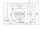
- FIG. 4 is a block diagram showing a configuration example of the EVS device 122 according to this embodiment.
- the EVS device 122 includes a pixel array section 201, an X arbiter 202 and a Y arbiter 203, an event signal processing circuit 204, a system control circuit 205, an output interface (I/F) 206, Prepare.
- I/F output interface
- the pixel array section 201 has a configuration in which a plurality of event pixels 20 each detecting an event based on a change in luminance of incident light are arranged in a two-dimensional lattice.
- the row direction also referred to as “row direction” refers to the arrangement direction of pixels in a pixel row (horizontal direction in the drawings)
- the column direction also referred to as “column direction” refers to It refers to the arrangement direction of pixels in a pixel column (vertical direction in the drawings).
- Each event pixel 20 has a photoelectric conversion element that generates a charge according to the luminance of incident light, and when detecting a change in the luminance of incident light based on the photocurrent that flows from the photoelectric conversion element, requests reading from itself. request to the X arbiter 202 and Y arbiter 203, and according to arbitration by the X arbiter 202 and Y arbiter 203, an event signal indicating detection of an event is output.
- Each event pixel 20 detects the presence or absence of an event depending on whether or not the photocurrent corresponding to the luminance of incident light has changed by exceeding a predetermined threshold. For example, each event pixel 20 detects as an event that the change in brightness exceeds a predetermined threshold (positive event) or falls below it (negative event).
- the event pixel 20 When the event pixel 20 detects an event, it outputs a request to the X arbiter 202 and the Y arbiter 203 to request permission to output an event signal representing the occurrence of the event.
- the event pixel 20 outputs an event signal to the event signal processing circuit 204 when it receives a response indicating permission to output the event signal from each of the X arbiter 202 and the Y arbiter 203 .
- the X arbiter 202 and the Y arbiter 203 arbitrate requests requesting the output of event signals supplied from each of the plurality of event pixels 20, and respond based on the arbitration results (permission/non-permission of event signal output), and A reset signal for resetting event detection is sent to the event pixel 20 that issued the request.
- the event signal processing circuit 204 generates and outputs event data by executing predetermined signal processing on the event signal input from the event pixel 20 .
- the change in the photocurrent generated by the event pixel 20 can also be regarded as the change in the amount of light (luminance change) incident on the photoelectric conversion portion of the event pixel 20 . Therefore, it can be said that an event is a light amount change (brightness change) of the event pixel 20 exceeding a predetermined threshold.
- the event data representing the occurrence of an event includes at least position information such as coordinates representing the position of the event pixel 20 where the change in the amount of light has occurred as an event.
- the event data can also include the polarity of the change in the amount of light in addition to the positional information.
- the event data is the relative time when the event occurred. It implicitly contains time information representing
- the event signal processing circuit 204 includes time information such as a time stamp that indicates the relative time when the event occurred before the interval between the event data is not maintained as it was when the event occurred. good too.
- the system control circuit 205 is composed of a timing generator that generates various timing signals. 204 or the like is controlled.
- the output I/F 206 outputs the event data output in units of rows from the event signal processing circuit 204 to the processing unit 14 as an event stream at any time, that is, asynchronously.
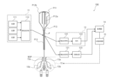
- FIG. 5 is a block diagram showing another more specific configuration example of the particle sorting device 100 according to an embodiment of the present technology.
- the particle sorting apparatus 100 includes a light source 111 and a light guide optical system 112 that constitute an irradiation unit 11, a detection optical system 121 that constitutes a detection unit 12, an EVS device 122, and a light detection unit 123, a fractionation control unit 13, a processing unit 14, and a charging unit 15a and a counter electrode 15b that constitute the fractionation unit 15. Observe the image of the emitted light.
- the light source 111, the light guide optical system 112, the detection optical system 121, the EVS device 122, the light detection unit 123, the fractionation control unit 13, the processing unit 14, and the fractionation unit 15 are the same as those shown in FIGS. may be partially or wholly the same as those described using . Note that the analysis unit 16 is omitted in FIG.
- the configuration of the flow path P is different from that of the particle sorting device 100 shown in FIG.
- the flow path P is not limited to the flow path formed in the two-dimensional or three-dimensional substrate T such as plastic or glass shown in FIG. Channels such as those used in cytometers can also be used.
- the sheath liquid and sample liquid are injected into a conical container.
- the conical container is installed with its apex facing vertically downward, and a tube or the like for introducing the sheath liquid is connected to the upper side surface.
- the upper surface of the conical container is open and the vibrating element is mounted sealed with an O-ring.
- the sample liquid is injected vertically from above the container.
- the conical container narrows at the bottom, and is connected to a cuvette portion in which a linear flow path P13 is formed.
- a laminar flow is formed in the conical container in such a manner that the sheath liquid surrounds the sample liquid, and when the laminar flow proceeds to the cuvette portion as it is, detection is performed by irradiation of light in the linear flow path P13.
- a detachable outlet nozzle is installed at the end point of the straight flow path P13, and the connecting portion has a slope shape that narrows continuously from the cuvette outlet to the outlet nozzle.
- FIG. 8 is a schematic diagram showing a specific example of the optical system of the particle sorting device 100 according to one embodiment of the present technology.
- FIG. 8 shows the light source 111 and the light guide optical system 112 constituting the irradiation unit 11, the detection optical system 121 constituting the detection unit 12, the EVS device 122, and the light detection unit in the particle sorting apparatus 100 according to the present embodiment.
- 123, and the fractionation control unit 13, the processing unit 14, the fractionation unit 15, and the analysis unit 16 are described above with reference to FIGS. Some or all of them may be similar to those described. Note that, in FIG. 8, photodetectors other than the forward scattered light detector in the photodetector 123 are omitted.
- the particle sorting device 100 has seven light sources, which emit lights of different wavelengths.
- the light emitted from each light source is condensed at different positions of the linear flow path P13 inside the cuvette via a light guiding optical system 112 such as a lens, beam splitter or mirror.
- a light guiding optical system 112 such as a lens, beam splitter or mirror.
- the particles flowing through the straight flow path P13 are irradiated with the light to generate fluorescence and forward scattered light.
- the forward scattered light is incident on the objective lens, and the forward scattered light collected by the objective lens is separated by a half mirror, and one of the separated lights is collected by the collecting lens and received by the EVS device. Imaged at different positions on the plane.
- the excitation light is removed by a light shielding mask, the light is condensed by a condenser lens, and the disturbance component is removed by a field stop (pinhole).
- Unwanted light components are removed by a filter (BPF) and detected by a forward scattered light (FSC) detector.
- FIG. 2 is a flowchart showing operation examples according to the present embodiment. Note that the execution of the operation described later may be controlled by a controller (not shown) or the like that controls the particle sorting device 100 .
- step S101 the EVS device 122 is activated (step S101), and fluid containing particles (for example, a biological sample) is started to be delivered to the channel P (step S102).
- step S103 light output from the irradiation unit 11 for irradiating light from the plurality of light sources 111 is started (step S103: irradiation step).
- step S103 the photodetector 123 may be activated. Note that the execution order of steps S101 to S103 may be changed.
- step S104 when sorting is started (step S104), the EVS device 122 detects changes in the brightness of the light emitted from the particles as events (step S105: detection step), and inputs the detection results to the processing unit 14. do.
- a plurality of specific spots 110 on the flow path P are irradiated with light from the irradiation section 11 . Therefore, when particles contained in the fluid sent to the flow path P pass through the plurality of spots 110, each spot 110 radiates fluorescence, scattered light, and the like. These lights emitted from each spot 110 are incident on the light receiving surface of the EVS device 122 via the detection optical system 121 . Therefore, each event pixel 20 in the EVS device 122 detects, as a positive event and a negative event, the luminance change due to the light image emitted when each particle passes each spot 110 . Event data detected for each event pixel 20 is output from the EVS device 122 to the processing unit 14 at any time, that is, asynchronously.
- the event data including the polarity and time stamp of only the event pixels 20 where the event has occurred is output from the EVS device 122 to the processing unit 14 as a stream (event stream), all pixels are output. Compared with the method of outputting the amount of received light, it is possible to greatly reduce the amount of data transfer.
- the processing unit 14 acquires an event stream for each particle based on the event data for each event pixel 20 output from the EVS device 122 (step S106).
- the event stream for each particle may be a set of event streams for each event pixel 20 .
- the processing unit 14 determines the velocity of each particle based on the event stream for each particle (step S107). In addition, the processing unit 14 calculates a delay time (Delay Time) from each particle velocity and the liquid feeding distance (step S108). At the same time as calculating the delay time, the processing unit 14 makes a fractionation determination based on the information about the particles acquired by the photodetection unit 123, and generates a fractionation control signal including information about the presence or absence of charge, size, etc. do. Next, the fractionation control section 13 controls the charging section 15a in the fractionation section 15 according to the delay time and the fractionation control signal to carry out sorting (step S109: fractionation control step).
- step S110 it is determined whether or not to end the sorting (step S110), and if not (NO in step S110), the process returns to step S105 and the subsequent operations are executed.
- step S110 when sorting is to be finished (YES in step S110), the light output from the irradiation unit 11 is stopped (step S111), and the delivery of the fluid containing particles to the flow path P is stopped (step S112). , this operation ends.
- FIG. 7 is a flowchart showing a more detailed operation example of the event stream acquisition operation shown in step S106 of FIG.
- step S106 of FIG. 7 in the event stream acquisition operation shown in step S106 of FIG. It is determined whether or not a particle has arrived at a specific spot 110 on P (step S121). Note that the monitoring of the event stream by the processing unit 14 may be continuously performed after the operation shown in FIG. 6 is started.
- the processing unit 14 When particles arrive at a specific spot on the channel P (YES in step S121), the processing unit 14 starts collecting event data after the arrival of the particles, including event data indicating the arrival of the particles (step S122). . Note that all the event data input from the EVS device 122 may be accumulated in a predetermined storage area separately from the collection of event data in step S122.
- the processing unit 14 monitors the sequence of event data (event stream) input from the EVS device 122 to determine whether or not the particles have finished passing through a specific spot 110 on the channel P (step S123). Then, when the particles have finished passing through the specific spot 110 on the channel P (YES in step S123), the processing unit 14 stops collecting event data (step S124), and determines the flow rate from the collected event data. An event stream for each particle passing through a specific spot 110 on the path P is generated for each event pixel 20 (step S125). After that, the process returns to the operation shown in FIG.
- an irradiation unit having a plurality of light sources and irradiating particles contained in the fluid with light from the plurality of light sources; a detection unit comprising a plurality of pixels for detecting, as an event, changes in luminance of light emitted from the particles due to irradiation with the light; a fractionation control unit that controls fractionation of the particles based on the event data detected by the detection unit; A particle sorting device.
- the irradiation unit is configured to irradiate the light from the plurality of light sources at different positions in the flow direction of the fluid.
- [3] The particle sorting device according to [1] or [2], wherein the detection unit asynchronously detects a change in brightness of the light as an event.
- the event data is any one or more of the group consisting of position information of a pixel where the event is detected, time information of the event detection, and polarity information of the event;
- the particle sorting device according to any one of 1.
- the particle sorting apparatus according to any one of [1] to [4], wherein the event data is position information of the pixel where the event was detected and time information when the event was detected.
- [6] The particle sorting device according to [5], wherein the positional information of the pixel that detected the event is gated in advance.
- the particle sorting apparatus according to any one of [1] to [6], further comprising a processing unit that determines the particle velocity based on the event data.
- a sorting section for sorting droplets containing the particles;
- the sorting unit includes a charging unit that charges the droplets,
- the particle fractionation device according to [7], wherein the fractionation control unit controls charging timing by the charging unit based on the particle velocity.
- the particle sorting device according to any one of [1] to [8], wherein the light emitted from the particles is fluorescence or scattered light.
- the particle sorting device according to [9], wherein the scattered light is forward scattered light.
- the event is detected by irradiation of light based on two light sources farthest apart in the flow direction of the fluid, [1] to [10] ].
- the particle sorting device according to any one of [1] to [11], wherein the particles are biologically relevant particles.
- a particle sorting method comprising:
Landscapes
- Chemical & Material Sciences (AREA)
- Health & Medical Sciences (AREA)
- Biochemistry (AREA)
- Physics & Mathematics (AREA)
- Life Sciences & Earth Sciences (AREA)
- Analytical Chemistry (AREA)
- General Health & Medical Sciences (AREA)
- General Physics & Mathematics (AREA)
- Immunology (AREA)
- Pathology (AREA)
- Dispersion Chemistry (AREA)
- Engineering & Computer Science (AREA)
- Signal Processing (AREA)
- Nuclear Medicine, Radiotherapy & Molecular Imaging (AREA)
- Investigating, Analyzing Materials By Fluorescence Or Luminescence (AREA)
Abstract
Description
以下に説明する実施形態は、本技術の代表的な実施形態の一例を示したものであり、これにより本技術の範囲が狭く解釈されることはない。なお、説明は以下の順序で行う。
1.本技術に係る粒子分取装置100の構成例
(1)粒子
(2)流路P
(3)照射部11
(4)検出部12
(5)分取制御部13
(6)処理部14
(7)分取部15
(8)解析部16
2.一実施形態
2-1.本実施形態に係る粒子分取装置100の構成例
(1)EVSデバイス122
(2)処理部14
2-2.EVSデバイス122の構成例
2-3.本実施形態に係る粒子分取装置100の他の構成例
2-4.本実施形態に係る粒子分取装置100の光学系の具体例
3.動作フロー例
工業用粒子は、例えば、有機又は無機高分子材料、金属等であってよい。有機高分子材料には、ポリスチレン、スチレン・ジビニルベンゼン、ポリメチルメタクリレート等が含まれ得る。無機高分子材料には、ガラス、シリカ、磁性体材料等が含まれ得る。金属には、金コロイド、アルミ等が含まれ得る。これらの粒子の形状は、一般的には球形であるのが普通であるが、本技術では、非球形であってよく、その大きさ、質量等も特に限定されない。
本技術においては、前記粒子として、特に、生体関連粒子が好ましい。
本技術は、特に、このように流路P内を異なる速度で各粒子が流れる場合において好適に用いることができる。
レーザー光としては、例えば、半導体レーザー、アルゴンイオン(Ar)レーザー、ヘリウム-ネオン(He-Ne)レーザー、ダイ(dye)レーザー、クリプトン(Cr)レーザー、半導体レーザーと波長変換光学素子とを組み合わせた固体レーザーなどが挙げられ、これらを2種以上組み合わせて用いることもできる。
また、処理部14は、光検出部123で取得した粒子に関する情報や光データ、入力された分取条件等に基づき分取判断を行い、分取制御信号を生成する。当該分取制御信号に基づき、分取制御部13は、各粒子を分取するか否かの判定を実行するよう分取部15を制御する。ここで、分取制御信号は、荷電部による荷電の有無、電荷の大きさに関する情報を含んでいてよい。
〔1〕
複数の光源を有し、流体に含まれる粒子に前記複数の光源からの光を照射する照射部と、
それぞれの前記光の照射により、前記粒子から放射した光の輝度変化をイベントとして検出する複数の画素を備える検出部と、
前記検出部で検出されたイベントデータに基づいて、前記粒子の分取を制御する分取制御部と、
を有する、粒子分取装置。
〔2〕
前記照射部は、前記複数の光源からの光を、前記流体の流れ方向に異なる位置で照射するように構成される、〔1〕に記載の粒子分取装置。
〔3〕
前記検出部は、前記光の輝度変化をイベントとして非同期で検出する、〔1〕又は〔2〕に記載の粒子分取装置。
〔4〕
前記イベントデータは、前記イベントを検出した画素の位置情報、前記イベントを検出した時間情報、及び前記イベントの極性情報からなる群のうちいずれか1以上のデータである、〔1〕から〔3〕のいずれかに記載の粒子分取装置。
〔5〕
前記イベントデータは、前記イベントを検出した画素の位置情報、及び前記イベントを検出した時間情報である、〔1〕から〔4〕のいずれかに記載の粒子分取装置。
〔6〕
前記イベントを検出した画素の位置情報は、予めゲーティングされたものである、〔5〕に記載の粒子分取装置。
〔7〕
前記イベントデータに基づいて、前記粒子速度を決定する処理部を更に有する、〔1〕から〔6〕のいずれかに記載の粒子分取装置。
〔8〕
前記粒子を含む液滴を分取する分取部を更に有し、
前記分取部は、前記液滴に荷電する荷電部を備え、
前記分取制御部は、前記粒子速度に基づいて、前記荷電部による荷電タイミングを制御する、〔7〕に記載の粒子分取装置。
〔9〕
前記粒子から放射した光は、蛍光、又は散乱光である、〔1〕から〔8〕のいずれかに記載の粒子分取装置。
〔10〕
前記散乱光は、前方散乱光である、〔9〕に記載の粒子分取装置。
〔11〕
前記複数の光源が3つ以上の光源からなる場合、前記イベントは、前記流体の流れ方向に最も離れた2つの光源に基づく光の照射により、検出されたものである、〔1〕から〔10〕のいずれかに記載の粒子分取装置。
〔12〕
前記粒子は、生体関連粒子である、〔1〕から〔11〕のいずれかに記載の粒子分取装置。
〔13〕
複数の光源を有し、流体に含まれる粒子に前記複数の光源からの光を照射する照射工程と、
それぞれの前記光の照射により、前記粒子から放射した光の輝度変化をイベントとして検出する検出工程と、
前記検出工程で検出されたイベントデータに基づいて、前記粒子の分取を制御する分取制御工程と、
を含む、粒子分取方法。
11:照射部
110,110a~110g:スポット
111:光源
112:導光光学系
12:検出部
121:検出光学系
122:EVSデバイス
123:光検出部
13:分取制御部
14:処理部
15:分取部
15a:荷電部
15b:対向電極
16:解析部
20:イベント画素
201:画素アレイ部
202:Xアービタ
203:Yアービタ
204:イベント信号処理回路
205:システム制御回路
206:出力インタフェース(I/F)
P:流路
P11:サンプル液流路
P12a,P12b:シース液流路
P13:主流路、直線流路
D:粒子を含む液滴
BOP:ブレイクオフポイント
Claims (13)
- 複数の光源を有し、流体に含まれる粒子に前記複数の光源からの光を照射する照射部と、
それぞれの前記光の照射により、前記粒子から放射した光の輝度変化をイベントとして検出する複数の画素を備える検出部と、
前記検出部で検出されたイベントデータに基づいて、前記粒子の分取を制御する分取制御部と、
を有する、粒子分取装置。 - 前記照射部は、前記複数の光源からの光を、前記流体の流れ方向に異なる位置で照射するように構成される、請求項1に記載の粒子分取装置。
- 前記検出部は、前記光の輝度変化をイベントとして非同期で検出する、請求項1に記載の粒子分取装置。
- 前記イベントデータは、前記イベントを検出した画素の位置情報、前記イベントを検出した時間情報、及び前記イベントの極性情報からなる群のうちいずれか1以上のデータである、請求項1に記載の粒子分取装置。
- 前記イベントデータは、前記イベントを検出した画素の位置情報、及び前記イベントを検出した時間情報である、請求項1に記載の粒子分取装置。
- 前記イベントを検出した画素の位置情報は、予めゲーティングされたものである、請求項5に記載の粒子分取装置。
- 前記イベントデータに基づいて、粒子速度を決定する処理部を更に有する、請求項1に記載の粒子分取装置。
- 前記粒子を含む液滴を分取する分取部を更に有し、
前記分取部は、前記液滴に荷電する荷電部を備え、
前記分取制御部は、前記粒子速度に基づいて、前記荷電部による荷電タイミングを制御する、請求項7に記載の粒子分取装置。 - 前記粒子から放射した光は、蛍光、又は散乱光である、請求項1に記載の粒子分取装置。
- 前記散乱光は、前方散乱光である、請求項9に記載の粒子分取装置。
- 前記複数の光源が3つ以上の光源からなる場合、前記イベントは、前記流体の流れ方向に最も離れた2つの光源に基づく光の照射により検出されたものである、請求項1に記載の粒子分取装置。
- 前記粒子は、生体関連粒子である、請求項1に記載の粒子分取装置。
- 複数の光源を有し、流体に含まれる粒子に前記複数の光源からの光を照射する照射工程と、
それぞれの前記光の照射により、前記粒子から放射した光の輝度変化をイベントとして検出する検出工程と、
前記検出工程で検出されたイベントデータに基づいて、前記粒子の分取を制御する分取制御工程と、
を含む、粒子分取方法。
Priority Applications (3)
| Application Number | Priority Date | Filing Date | Title |
|---|---|---|---|
| JP2023538220A JPWO2023007777A1 (ja) | 2021-07-26 | 2022-02-08 | |
| US18/578,428 US20240319069A1 (en) | 2021-07-26 | 2022-02-08 | Particle sorting apparatus and particle sorting method |
| CN202280051429.6A CN117836606A (zh) | 2021-07-26 | 2022-02-08 | 粒子分选装置和粒子分选方法 |
Applications Claiming Priority (2)
| Application Number | Priority Date | Filing Date | Title |
|---|---|---|---|
| JP2021-121980 | 2021-07-26 | ||
| JP2021121980 | 2021-07-26 |
Publications (1)
| Publication Number | Publication Date |
|---|---|
| WO2023007777A1 true WO2023007777A1 (ja) | 2023-02-02 |
Family
ID=85086653
Family Applications (1)
| Application Number | Title | Priority Date | Filing Date |
|---|---|---|---|
| PCT/JP2022/004854 Ceased WO2023007777A1 (ja) | 2021-07-26 | 2022-02-08 | 粒子分取装置及び粒子分取方法 |
Country Status (4)
| Country | Link |
|---|---|
| US (1) | US20240319069A1 (ja) |
| JP (1) | JPWO2023007777A1 (ja) |
| CN (1) | CN117836606A (ja) |
| WO (1) | WO2023007777A1 (ja) |
Citations (6)
| Publication number | Priority date | Publication date | Assignee | Title |
|---|---|---|---|---|
| WO2009078307A1 (ja) * | 2007-12-14 | 2009-06-25 | Bay Bioscience Kabushiki Kaisha | 液体フローに含まれる生物学的粒子を分別する装置ならびにその方法 |
| JP2014202573A (ja) * | 2013-04-04 | 2014-10-27 | ソニー株式会社 | 粒子分取装置及び粒子分取方法 |
| WO2015114750A1 (ja) * | 2014-01-29 | 2015-08-06 | 株式会社島津製作所 | フローサイトメータ |
| JP2020510222A (ja) * | 2017-04-11 | 2020-04-02 | ソニー株式会社 | 微粒子分類装置と遅延時間決定方法 |
| JP6685057B1 (ja) * | 2019-07-30 | 2020-04-22 | 株式会社Cybo | イメージングフローサイトメーター、ソート方法、及び、キャリブレーション方法 |
| WO2020149042A1 (ja) * | 2019-01-15 | 2020-07-23 | ソニー株式会社 | 微小粒子分取装置、微小粒子分取システム、液滴分取装置、及び液滴制御装置、並びに、液滴制御用プログラム |
-
2022
- 2022-02-08 CN CN202280051429.6A patent/CN117836606A/zh not_active Withdrawn
- 2022-02-08 WO PCT/JP2022/004854 patent/WO2023007777A1/ja not_active Ceased
- 2022-02-08 JP JP2023538220A patent/JPWO2023007777A1/ja not_active Withdrawn
- 2022-02-08 US US18/578,428 patent/US20240319069A1/en active Pending
Patent Citations (6)
| Publication number | Priority date | Publication date | Assignee | Title |
|---|---|---|---|---|
| WO2009078307A1 (ja) * | 2007-12-14 | 2009-06-25 | Bay Bioscience Kabushiki Kaisha | 液体フローに含まれる生物学的粒子を分別する装置ならびにその方法 |
| JP2014202573A (ja) * | 2013-04-04 | 2014-10-27 | ソニー株式会社 | 粒子分取装置及び粒子分取方法 |
| WO2015114750A1 (ja) * | 2014-01-29 | 2015-08-06 | 株式会社島津製作所 | フローサイトメータ |
| JP2020510222A (ja) * | 2017-04-11 | 2020-04-02 | ソニー株式会社 | 微粒子分類装置と遅延時間決定方法 |
| WO2020149042A1 (ja) * | 2019-01-15 | 2020-07-23 | ソニー株式会社 | 微小粒子分取装置、微小粒子分取システム、液滴分取装置、及び液滴制御装置、並びに、液滴制御用プログラム |
| JP6685057B1 (ja) * | 2019-07-30 | 2020-04-22 | 株式会社Cybo | イメージングフローサイトメーター、ソート方法、及び、キャリブレーション方法 |
Non-Patent Citations (2)
| Title |
|---|
| AHMED NABIL BELBACHIR ; MICHAEL HOFSTATTER ; MARTIN LITZENBERGER ; PETER SCHON: "High-Speed Embedded-Object Analysis Using a Dual-Line Timed-Address-Event Temporal-Contrast Vision Sensor", IEEE TRANSACTIONS ON INDUSTRIAL ELECTRONICS, IEEE SERVICE CENTER, PISCATAWAY, NJ., USA, vol. 58, no. 3, 1 March 2011 (2011-03-01), USA , pages 770 - 783, XP011345430, ISSN: 0278-0046, DOI: 10.1109/TIE.2010.2095390 * |
| LEE, SEONG-WHAN ; LI, STAN Z: "SAT 2015 18th International Conference, Austin, TX, USA, September 24-27, 2015", vol. 10317 Chap.21, 2 June 2017, SPRINGER , Berlin, Heidelberg , ISBN: 3540745491, article RIDWAN IFFATUR; CHENG HOWARD: "An Event-Based Optical Flow Algorithm for Dynamic Vision Sensors", pages: 182 - 189, XP047417518, 032548, DOI: 10.1007/978-3-319-59876-5_21 * |
Also Published As
| Publication number | Publication date |
|---|---|
| US20240319069A1 (en) | 2024-09-26 |
| JPWO2023007777A1 (ja) | 2023-02-02 |
| CN117836606A (zh) | 2024-04-05 |
Similar Documents
| Publication | Publication Date | Title |
|---|---|---|
| CN107202903B (zh) | 样本分析仪及其样本分析方法 | |
| CN110121643B (zh) | 用于流式细胞仪的光学检测系统、流式细胞仪系统及其使用方法 | |
| JP5446563B2 (ja) | 微小粒子分取装置、および該微小粒子分取装置を用いたフローサイトメーター | |
| EP1574838A1 (en) | Device for collecting information on biological particle | |
| CN102435313A (zh) | 荧光强度补偿方法及荧光强度计算装置 | |
| JP7568048B2 (ja) | 微小粒子分取装置、微小粒子分取システム、液滴分取装置、及び液滴制御装置、並びに、液滴制御用プログラム | |
| WO2021192786A1 (ja) | イメージングフローサイトメーター、ソート方法、及びキャリブレーション方法 | |
| CN108474730A (zh) | 微粒测量设备、信息处理设备、以及信息处理方法 | |
| US8913242B2 (en) | Fine particle measurement device | |
| CN111521548A (zh) | 一种颗粒分析分选装置及方法 | |
| JPH08128944A (ja) | 粒子分類装置 | |
| US12298218B2 (en) | Particle detection apparatus, information processing apparatus, information processing method, and particle detection method | |
| JP7677154B2 (ja) | 光学測定装置及び情報処理システム | |
| CN117501107A (zh) | 生物样品分析装置 | |
| WO2023007777A1 (ja) | 粒子分取装置及び粒子分取方法 | |
| US11686662B2 (en) | Microparticle sorting device and method for sorting microparticles | |
| JP6249049B2 (ja) | 微小粒子測定装置 | |
| US20230375459A1 (en) | Particle detection device, particle detection system, and particle detection method | |
| US20250237596A1 (en) | Particle sorting system and particle sorting method | |
| WO2023276298A1 (ja) | 生体試料分析システム、情報処理装置、情報処理方法及び生体試料分析方法 | |
| US20250389637A1 (en) | Droplet sorting system, droplet sorting method, and droplet sorting program | |
| US20250334504A1 (en) | Particle sorting system, particle sorting method, and particle sorting program | |
| US20250377281A1 (en) | Biological sample analysis system and biological sample analysis method | |
| WO2026034014A1 (ja) | 粒子分析システム及び粒子分析装置 | |
| US20250347610A1 (en) | Flow cytometer and method for setting waveform parameters of signal for driving droplet-generating vibration element of flow cytometer |
Legal Events
| Date | Code | Title | Description |
|---|---|---|---|
| 121 | Ep: the epo has been informed by wipo that ep was designated in this application |
Ref document number: 22848861 Country of ref document: EP Kind code of ref document: A1 |
|
| WWE | Wipo information: entry into national phase |
Ref document number: 2023538220 Country of ref document: JP |
|
| WWE | Wipo information: entry into national phase |
Ref document number: 18578428 Country of ref document: US |
|
| WWE | Wipo information: entry into national phase |
Ref document number: 202280051429.6 Country of ref document: CN |
|
| NENP | Non-entry into the national phase |
Ref country code: DE |
|
| 122 | Ep: pct application non-entry in european phase |
Ref document number: 22848861 Country of ref document: EP Kind code of ref document: A1 |