WO2023007783A1 - 谷樋補修部材 - Google Patents
谷樋補修部材 Download PDFInfo
- Publication number
- WO2023007783A1 WO2023007783A1 PCT/JP2022/006539 JP2022006539W WO2023007783A1 WO 2023007783 A1 WO2023007783 A1 WO 2023007783A1 JP 2022006539 W JP2022006539 W JP 2022006539W WO 2023007783 A1 WO2023007783 A1 WO 2023007783A1
- Authority
- WO
- WIPO (PCT)
- Prior art keywords
- gutter
- valley
- base material
- repairing
- repairing member
- Prior art date
- Legal status (The legal status is an assumption and is not a legal conclusion. Google has not performed a legal analysis and makes no representation as to the accuracy of the status listed.)
- Ceased
Links
Images




Classifications
-
- E—FIXED CONSTRUCTIONS
- E04—BUILDING
- E04D—ROOF COVERINGS; SKY-LIGHTS; GUTTERS; ROOF-WORKING TOOLS
- E04D13/00—Special arrangements or devices in connection with roof coverings; Protection against birds; Roof drainage ; Sky-lights
- E04D13/04—Roof drainage; Drainage fittings in flat roofs, balconies or the like
- E04D13/064—Gutters
-
- E—FIXED CONSTRUCTIONS
- E04—BUILDING
- E04G—SCAFFOLDING; FORMS; SHUTTERING; BUILDING IMPLEMENTS OR AIDS, OR THEIR USE; HANDLING BUILDING MATERIALS ON THE SITE; REPAIRING, BREAKING-UP OR OTHER WORK ON EXISTING BUILDINGS
- E04G23/00—Working measures on existing buildings
- E04G23/02—Repairing, e.g. filling cracks; Restoring; Altering; Enlarging
Definitions
- the present disclosure relates to a valley gutter repair member for repairing a valley gutter that is provided in a valley formed by two adjacent roofs and drains rainwater.
- a valley gutter that is provided in a valley formed by two adjacent roofs and drains rainwater is known.
- the valley gutter of Patent Document 1 is formed by bending a valley gutter material in which a strip-shaped sealing sheet is attached to the longitudinal end of the upper surface of a strip-shaped plate in which the surface of a core material made of a metal plate is coated with a soft resin. be done. To the edge of the gutter where the band-shaped sealing sheet is adhered, the part of the other gutter where the sealing sheet is not attached is fixed.
- the gutter may deteriorate and need to be repaired.
- this repair there are the following problems. Specifically, buildings in which valley gutters are installed are often facilities for business use, and it is particularly desirable to shorten the repair period.
- buildings in which valley gutters are installed are often facilities for business use, and it is particularly desirable to shorten the repair period.
- the upper opening of the gutter is often narrow, it is also desired to facilitate the construction work of passing the repair member through the narrow opening and installing it in the gutter in a predetermined shape after passing through the opening.
- the repair member is vulnerable to environmental changes, it is likely to deteriorate, so it may be necessary to perform another repair in a short period of time.
- An object of the present disclosure is to make it possible to repair a gutter in a short period of time by facilitating the construction work of installing it in the gutter repair member, and to realize a configuration that is resistant to environmental changes. .
- a gutter repair member is a gutter repair member for repairing a gutter that is provided in a valley formed by two adjacent roofs and drains rainwater, and has a sheet-like base material. and a resin layer covering at least one of both sides in the thickness direction of the base material, and the base material has a bending rigidity within the range of 0.05 to 0.13 (Pa ⁇ m 4 ). It is a repair part.
- the gutter repairing member of one aspect of the present disclosure it becomes easier to perform the installation work for the gutter, so the gutter can be repaired in a short period of time, and a configuration that is resistant to environmental changes can be realized.
- FIG. 1 is a cross-sectional view showing a gutter-equipped roof structure provided with a gutter repairing member according to an embodiment;
- FIG. 1. It is a perspective view which cut
- FIG. 5 is a diagram showing test results of evaluating the flexibility and self-standing of a gutter repairing member with a plurality of gutter repairing members having different bending stiffnesses.
- FIG. 11 is an enlarged perspective view of a corner of a box-shaped longitudinal end formed by a gutter repairing member in another example of the embodiment; In another example of the embodiment, it is a schematic diagram of a longitudinal end of a gutter repaired with a gutter repairing member.
- FIG. 1 is a cross-sectional view showing a roof structure 10 with a gutter provided with a gutter repairing member 20 according to an embodiment.
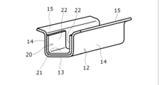
- FIG. 2 is a perspective view showing a longitudinal part of the gutter 12 and the gutter repairing member 20 taken out from FIG. 1 and partly cut away.
- FIG. 3 is a schematic diagram (a) showing thickness comparison of each component of the gutter material 50 and a schematic diagram (b) showing thickness comparison of each component of the gutter repairing member 20 in the embodiment. .
- the gutter-equipped roof structure 10 provided with the gutter repairing member 20 includes, for example, two adjacent roofs 60 and 61 and the gutter 12 provided in the valley portion 62 formed by the two roofs 60 and 61. consists of The gutter-equipped roof structure 10 is provided, for example, on the roof of a factory or on the roof above the platform of a station.
- Each roof 60, 61 is, for example, a folded roof, a corrugated slate, or the like, and is supported by supports 63 made of steel strips or the like. Between the receiving member 63 and the roofs 60, 61, the flange 15 of the gutter 12 or the flanges of the gutter and the gutter receiving member (not shown) are sandwiched. Thereby, the valley gutter 12 is supported under the opening between the eaves of the two roofs 60 and 61. - ⁇
- the valley gutter 12 extends along the edge of the eaves of the roofs 60 and 61, and includes a bottom wall 13, side walls 14 standing upward from both ends of the bottom wall 13 in the width direction, and diagonally outward from the upper ends of the side walls 14. and an upwardly extending flange 15 .
- the valley gutter 12 collects rainwater that has flowed in from the eaves of the two roofs 60 and 61, and drains it through a downpipe (not shown) from a drainage outlet (not shown) provided at a part or a plurality of positions in the longitudinal direction. drains downwards.
- the longitudinal direction of the gutter 12 is referred to as the front-rear direction
- the lateral direction perpendicular to the front-rear direction of the gutter 12 is referred to as the width direction.
- the gutter material 50 forming the gutter 12 includes a sheet-like core material 51 made of a steel plate and resin layers 52 and 53 covering both sides of the core material 51 in the thickness direction. and have.
- the valley gutter 12 is formed by cutting out a predetermined length from the coil-wound valley gutter material 50 and bending it.
- the resin layers 52 and 53 are provided on both upper and lower surfaces of the core member 51 at the intermediate portion in the width direction of the gutter 12 formed as shown in FIG.
- the thicknesses d1, d2, and d3 of the core material 51 and the resin layers 52 and 53 may be substantially the same.
- the gutter repair member 20 is a member for repairing the gutter 12, is provided inside the gutter 12, and covers part or all of the inner surface of the gutter 12 during use. Fixed.
- the valley gutter repairing member 20 is wound in a coil shape, and a required length is cut out at the repair site.
- the cut-out gutter repairing member 20 is bent in advance into a shape close to the shape along the inner surface of the inner bottom wall 13 and two side walls 14 of the gutter 12 . Then, it is pushed from the upper side of the opening 64 between the eaves of the two roofs 60 and 61 to the lower side of the opening 64 while being elastically bent, and along the inner surface shape of the gutter 12, one of the exposed portions of the inner surface of the gutter 12 is pushed.
- the gutter repairing member 20 is fitted inside the gutter 12 and formed in a groove shape having a bottom wall 21 and side walls 22 erected upward from both ends of the bottom wall 21 in the width direction.
- the gutter repairing member 20 and the gutter 12 are superimposed and fixed with one or more screws.
- the gutter repairing member 20 includes a sheet-like base material 24 made of a metal plate such as a steel plate, and resin layers 25 and 26 covering both sides of the base material 24 in the thickness direction. Configured. Such resin layers 25 and 26 are provided so as to be laminated substantially entirely on both side surfaces of the base material 24 in a flat plate state before the gutter repairing member 20 is bent.
- the resin layers 25 and 26 are provided on both upper and lower surfaces of the base material 24 in the middle portion of the gutter repairing member 20 in the width direction.
- the thickness d4 of the base material 24 is smaller than the thickness d1 of the core material 51 forming the gutter material 50, for example.
- the thickness d4 of the base material 24 is less than half the thickness d1 of the core material 51 .
- the thicknesses d5 and d6 of the resin layers 25 and 26 of the gutter repairing member 20 can be substantially the same as the thicknesses d3 and d4 of the resin layers 52 and 53 of the gutter material 50, respectively.
- the base material 24 of the gutter repairing member 20 has a bending rigidity of 0.05 to 0.13 (Pa ⁇ m 4 ) under the condition that the width is 910 mm in a flat plate state before bending. have performance.
- the bending stiffness is determined from the width and thickness of the gutter repair member 20 and the Young's modulus based on the material.
- the gutter repairing member 20 does not become too hard and has high flexibility, so that it becomes easy to bend, and the work of bending it into the narrow gutter 12 is facilitated.
- it can have moderate self-supporting property, it can maintain the state after bending after being bent.
- both the upper and lower surfaces of the base material 24 are covered with the resin layers 25 and 26, so it is resistant to environmental changes such as temperature changes, rainwater pouring, and rainwater flow. Therefore, installation work in a narrow installation space can be easily performed, and since it is easy to form in advance a shape close to the shape after installation, workability is improved, and the valley gutter 12 can be installed in a short period of time. Repair work can be carried out. For example, when the structure in which the gutter 12 is provided is a facility for business use, the function of the gutter 12 can be restored to some extent without removing the gutter 12 only by working at night when the work of the facility is stopped. It becomes easy to complete the repair work of the valley gutter 12 while exerting it.
- FIG. 4 shows test results of evaluating the flexibility and self-standing of the gutter repairing member 20 with a plurality of gutter repairing members having different bending stiffnesses.
- the test was conducted under the condition that the width of the base material 24 of the gutter repairing member 20 was 910 mm. Flexibility and independence of a plurality of valley gutter repair members 20 in which the bending rigidity of the base material 24 is varied in the range of 0.04 (Pa ⁇ m 4 ) to 0.15 (Pa ⁇ m 4 ) evaluated.
- the configurations and dimensions of the resin layers 25 and 26 of the gutter repairing member 20 were all the same in the test. In the test results of FIG.
- ⁇ in the “Flexibility” column indicates that there is practically sufficient flexibility for bending the gutter repairing member 20 into the shape after installation. ⁇ indicates that there is sufficient flexibility for practical use, but the flexibility is inferior to the case of ⁇ , and ⁇ indicates that the flexibility is practical because the valley gutter repair member 20 is bent into the shape after installation. It shows that you are short of water.
- ⁇ in the column of "Self-support” indicates that after the gutter repairing member 20 is bent into the shape after installation, it has practically sufficient shape-maintaining function to maintain its shape, that is, it is self-supporting.
- ⁇ indicates that there is sufficient self-support in practical use, but the self-support is inferior to the case of ⁇ , and ⁇ indicates that the gutter repair member 20 is in the shape after installation. It shows that the self-sustainability that can maintain the shape after bending is practically insufficient.
- the ends of the gutter 12 and the gutter repairing member 20 are aligned.
- the same sealing member (sealant) can be used for the gutter 12 and the gutter repairing member 20. As a result, it is possible to prevent adverse reaction due to contact of sealing members made of different materials.
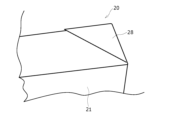
- FIG. 5 is an enlarged perspective view of a corner of a box-shaped longitudinal end formed by the gutter repairing member 20 in another example of the embodiment.
- a box shape is formed by the gutter repairing member 20 inside the gutter 12 (FIG. 1, etc.). Then, when the longitudinal ends of the box shape are formed, the remaining portions at the corners of the longitudinal ends and the widthwise ends are overlapped in a triangular shape on the outer side, and the surplus triangular portions are formed on the outer surfaces of the end walls of the longitudinal ends.
- a Yachiyo-fold portion 28 is formed by overlapping the shaped portions. Even at this time, similarly to the configuration of FIGS.
- the bending rigidity is 0.05 to 0.13 (Pa ⁇ m 4 ). Therefore, it is easy to crease the box shape in advance before installing it in the valley gutter 12, and it is easy to form the box shape. This makes it easier to install the gutter repair member 20 inside the gutter 12 .
- Other configurations and actions in this example are the same as those in FIGS.
- FIG. 6 is a schematic diagram of the longitudinal end of the gutter 12 repaired with the gutter repairing member 20 in another example of the embodiment.
- the longitudinal ends of the gutter 12 are covered with the gutter repairing member 20 so as to protrude outward to form a so-called end overhang, so that the longitudinal ends and valleys of the gutter 12 are separated from each other.
- the bending rigidity of the base material 24 of the gutter repairing member 20 is appropriately regulated, so that the gutter repairing member 20 can be bent even in a narrow installation place. Since it is easy to install, it is easy to perform the installation work including the work of forming the overhang.
- this configuration can prevent wind from entering between the longitudinal end of the gutter 12 and the longitudinal end of the gutter repairing member 20 to prevent the gutter repairing member 20 from being turned up.
- the gutter 12 and the gutter repairing member 20 are shown separated from each other with a gap therebetween, but in reality, they are superimposed on each other without any gap.
- Other configurations and actions in this example are the same as those in FIGS.
- the present disclosure is not limited to this, and the gutter repairing member A configuration in which a resin layer is provided only on one of both surfaces in the thickness direction of the substrate 24 of the substrate 20 may be employed.
- the gutter repair member 20 when the gutter repair member 20 is attached to the gutter 12 so as to cover the upper surface of the gutter 12, the gutter repair member 20 includes the upper surface of the base material 24, and the gutter and 12 are in the opposite thickness direction.
- a resin layer may be provided only on one surface.
- the gutter repair member 20 when the gutter repair member 20 is attached to the gutter 12 so as to cover the lower surface of the gutter 12, the thickness direction on the side opposite to the gutter 12, including the lower surface of the base material 24 of the gutter repair member 20.
- a resin layer may be provided only on the other surface.
- the base material of the gutter repairing member 20 may be subjected to surface treatment such as resin coating to give the base material a special function such as a rust prevention function. can.
- the base material of the gutter repairing member 20 may have a configuration in which punching processing, which is a process of punching a large number of holes, is performed. As a result, the weight of the gutter repairing member 20 can be reduced.
- the resin layer is provided on at least one surface of the substrate 24 in the thickness direction, it is possible to prevent rainwater from passing through the gutter repairing member 20 in the thickness direction.
- the inner surface of the gutter 12 is repaired. It is also possible to have a configuration in which a groove-shaped valley gutter repairing member 20 is superimposed thereon so as to cover substantially the entirety of. 1 to 3, the bending rigidity of the base material 24 of the gutter repairing member 20 is appropriately regulated, so that the planar gutter repairing member at the tip of the gutter repairing member 20 Concavity and convexity can be made less likely to occur in the overlapped portion.
- the base material 24 of the gutter repairing member 20 maintains appropriate rigidity.
- the gutter repairing member 20 can easily follow the shape of the bottom of the gutter 12. ⁇ As a result, it is possible to provide a structure in which a gap between the gutter repairing member 20 and the gutter 12 is less likely to occur and water is less likely to enter.
- valley gutter roof structure 10 valley gutter roof structure, 12 valley gutter, 13 bottom wall, 14 side wall, 15 flange, 20 valley gutter repair member, 21 bottom wall, 22 side wall, 24 base material, 25, 26 resin layer, 28 Yachiyo fold portion, 50 Material for valley gutter, 51 core material, 52, 53 resin layer, 60, 61 roof, 62 valley, 63 receiver, 64 opening.
Landscapes
- Engineering & Computer Science (AREA)
- Architecture (AREA)
- Civil Engineering (AREA)
- Structural Engineering (AREA)
- Chemical & Material Sciences (AREA)
- Chemical Kinetics & Catalysis (AREA)
- Electrochemistry (AREA)
- Mechanical Engineering (AREA)
- Roof Covering Using Slabs Or Stiff Sheets (AREA)
Abstract
谷樋補修部材(20)は、隣り合う2つの屋根(60,61)によって形成される谷部(62)に設けられ、雨水を排水する谷樋(12)の補修用の谷樋補修部材(20)であって、シート状の基材と、基材の厚み方向両面の少なくとも一方を覆う樹脂層とを含む。基材は、曲げ剛性が0.05~0.13(Pa×m4)の範囲内の性能を有する。
Description
本開示は隣り合う2つの屋根によって形成される谷部に設けられ、雨水を排水する谷樋の補修用の谷樋補修部材に関する。
従来から、特許文献1に記載されているように、隣り合う2つの屋根によって形成される谷部に設けられ、雨水を排水する谷樋が知られている。特許文献1の谷樋は、金属板製の芯材の表面を軟質樹脂で被覆した帯状板の上面の長手方向端部に、帯状シーリングシートを貼着した谷樋用素材を曲げ加工して形成される。谷樋の帯状シーリングシートを貼着した端部には、他の谷樋のシーリングシートがない部分が固着される。
谷樋の使用状況等により谷樋の劣化が生じ、谷樋の補修が必要になる場合がある。この補修について、次の課題がある。具体的には、谷樋が設けられる建物は、業務用の施設であることが多く、特に補修期間を短くすることが望まれる。一方、谷樋は、上部の開口が狭いことが多いので、補修部材を狭い開口に通過させ、開口の通過後、所定の形状で谷樋に設置する施工作業を行いやすくすることも望まれる。また、補修部材が環境変化に弱いと、劣化しやすくなるので、再度の補修を短期間で行う必要が生じる場合がある。
本開示の目的は、谷樋補修部材において、谷樋に設置する施工作業を行いやすくすることにより、短時間での谷樋の補修を可能とし、かつ環境変化に強い構成を実現することである。
本開示の一態様の谷樋補修部材は、隣り合う2つの屋根によって形成される谷部に設けられ、雨水を排水する谷樋の補修用の谷樋補修部材であって、シート状の基材と、基材の厚み方向両面の少なくとも一方を覆う樹脂層と、を備え、基材は、曲げ剛性が0.05~0.13(Pa×m4)の範囲内の性能を有する、谷樋補修部材である。
本開示の一態様の谷樋補修部材によれば、谷樋に設置する施工作業を行いやすくなるので、短時間での谷樋の補修が可能となり、かつ環境変化に強い構成を実現できる。
以下、図面を参照しながら、本開示に係る谷樋補修部材の実施形態を説明する。なお、以下において複数の実施形態や変形例などが含まれる場合、それらの特徴部分を適宜に組み合わせて新たな実施形態を構築することは当初から想定されている。以下で説明する形状、配置、個数、数値、材料等は、説明のための例示であって、谷樋補修部材の仕様により適宜変更することができる。以下では全ての図面において同等の要素には同一の符号を付して説明する。
図1~図4を用いて実施形態を説明する。図1は、実施形態の谷樋補修部材20が設けられた谷樋付き屋根構造10を示す断面図である。図2は、図1から谷樋12及び谷樋補修部材20の長手方向一部を取り出し一部を切断して示す斜視図である。図3は、実施形態において、谷樋用素材50の各構成要素の厚み比較を示す模式図(a)と、谷樋補修部材20の各構成要素の厚み比較を示す模式図(b)である。
谷樋補修部材20が設けられる谷樋付き屋根構造10は、例えば、隣り合う2つの屋根60,61と、2つの屋根60,61によって形成される谷部62に設けられる谷樋12とを含んで構成される。谷樋付き屋根構造10は、例えば工場の屋根や、駅のプラットフォーム上側の屋根に設けられる。
各屋根60,61は、例えば、折半屋根や、波型スレート等であり、鋼帯等からなる受け具63に支持される。そして、受け具63と屋根60,61との間に、谷樋12のフランジ15、または、谷樋及び谷樋受け具(図示せず)のフランジが挟まれる。これにより、2つの屋根60,61の軒先間の開口下側に谷樋12が支持される。
谷樋12は、屋根60,61の軒先の先端縁に沿って延びており、底壁13と、底壁13の幅方向両端から上方に立設した側壁14と、側壁14の上端から斜め外側上方に延びたフランジ15とを有する。谷樋12は、2つの屋根60,61の軒先から流れ込んだ雨水を集水し、長手方向一部または複数位置に設けられた排水口(図示せず)から竪樋(図示せず)を介して下側に排水される。以下、谷樋12の長手方向を前後方向と記載し、谷樋12の前後方向に対し直交する横方向を幅方向と記載する。
図3(a)に示すように、谷樋12を形成する谷樋用素材50は、鋼板により形成されるシート状の芯材51と、芯材51の厚み方向両面を覆う樹脂層52,53と有する。谷樋12は、コイル状に巻かれた谷樋用素材50において、所定長さ分が切り出され、曲げ加工されることにより形成される。これにより、谷樋12を図1に示すように形成した状態で谷樋12の幅方向中間部において、芯材51の上下両面には樹脂層52,53が設けられる。芯材51及び各樹脂層52,53の厚みd1、d2、d3は、略同じとしてもよい。
図1に示すように、谷樋補修部材20は、谷樋12の補修用部材であり、谷樋12の内側に設けられ、使用時に、谷樋12の内面の一部または全部を覆うように固定される。谷樋補修部材20は、コイル状に巻かれており、補修を行う現場で必要な長さ分が切り出される。切り出された谷樋補修部材20は、予め谷樋12の内面の底壁13と2つの側壁14とからなる形状の内面に沿う形状に近い形状に曲げ加工される。そして、2つの屋根60,61の軒先間の開口64の上側から開口64の下側に弾性的に曲げながら押し込まれ、谷樋12の内面形状に沿って谷樋12の内面の露出部分の一部または全部を覆うように、谷樋12の内面に重ねた状態で固定される。谷樋補修部材20は、谷樋12内側に嵌め込まれた状態で、底壁21と、底壁21の幅方向両端から上方に立設した側壁22とを有する溝形状に形成される。谷樋補修部材20と谷樋12とは重ねられた状態で、1つまたは複数のビスによって固定される。
次に、谷樋補修部材20の材料構成を説明する。谷樋補修部材20は、図3(b)に示すように、鋼板等の金属板製のシート状の基材24と、基材24の厚み方向両面を覆う樹脂層25,26とを含んで構成される。このような樹脂層25,26は、谷樋補修部材20の曲げ加工前の平板状態で、基材24の両側面のそれぞれのほぼ全体に積層するように設けられる。谷樋補修部材20を図1に示すように溝形状に形成した状態では、谷樋補修部材20の幅方向中間部において、基材24の上下両面には樹脂層25,26が設けられる。基材24の厚みd4は、例えば谷樋用素材50を形成する芯材51の厚みd1より小さい。例えば、基材24の厚みd4は、芯材51の厚みd1の1/2以下である。一方、谷樋補修部材20の各樹脂層25,26の厚みd5,d6は、谷樋用素材50の各樹脂層52,53の厚みd3,d4と略同じとすることができる。
また、谷樋補修部材20の基材24は、曲げ加工前の平板状の状態で幅が910mmである条件で、曲げ剛性が0.05~0.13(Pa×m4)の範囲内の性能を有する。曲げ剛性は、谷樋補修部材20の幅及び厚みと、材料に基づくヤング率とから決定される。これにより、谷樋補修部材20は、硬くなり過ぎず、柔軟性を高くできるので、曲げやすくなり、狭い谷樋12内に押し込むように曲げる作業を行いやすくなる。また、適度な自立性を持つことができるので、曲げられた後、その曲げ加工後の状態を維持することができる。このため、谷樋12の外部で、予め谷樋12に合わせた設置後の形状に近い形状に作っておくことができる。これにより、谷樋補修部材20を、谷樋12の上部の狭い開口64に通過させ、所定の形状で谷樋12に設置する施工作業を行いやすくなることにより、谷樋12の短時間での補修が可能となる。
さらに、谷樋補修部材20において、基材24の上下両面が樹脂層25,26で被覆されるので、温度変化や、雨水の降りかかり、雨水の流れ等の環境変化に強くなる。このため、狭い設置空間への設置作業を容易に行えると共に、予め設置後の形状に近い形状に形成しておくことが容易であるので、施工性が高くなり、かつ短期間で谷樋12の補修作業を行うことができる。例えば、谷樋12が設けられる構造が、業務用の施設である場合に、その施設の業務が停止している夜間の作業のみで、谷樋12を取り外すことなく、谷樋12の機能をある程度発揮させながら谷樋12の補修作業を完了しやすくなる。
図4は、谷樋補修部材20の柔軟性及び自立性を、異なる曲げ剛性を持つ複数の谷樋補修部材で評価した試験結果を示している。試験は、谷樋補修部材20の基材24の幅が910mmの条件で行った。そして、基材24の曲げ剛性を、0.04(Pa×m4)~0.15(Pa×m4)の範囲で種々に異ならせた複数の谷樋補修部材20の柔軟性及び自立性を評価した。谷樋補修部材20の樹脂層25,26の構成及び寸法は試験ですべて同じとした。図4の試験結果において、「柔軟性」の欄の〇は、曲げやすさについて谷樋補修部材20を設置後の形状に曲げ形成するために実用上、十分な柔軟性があることを示し、△は、同じく実用上、十分な柔軟性があるが、〇の場合より柔軟性が劣ることを示し、×は、谷樋補修部材20を設置後の形状に曲げ形成するために柔軟性が実用上不足していることを示す。図4において、「自立性」の欄の〇は、谷樋補修部材20を設置後の形状に曲げ形成した後、その形状を維持するために実用上、十分な形状維持機能を有する、すなわち自立性が十分であることを示し、△は、同じく実用上、十分な自立性があるが、〇の場合より自立性が劣ることを示し、×は、谷樋補修部材20を設置後の形状に曲げ形成した後、その形状を維持できる自立性が実用上不足していることを示す。
図4の試験結果から実施形態の範囲に属する基材24の曲げ剛性が0.05~0.13(Pa×m4)の場合には、谷樋補修部材20の柔軟性及び自立性について、実用上十分であったため、実施形態の効果を確認できた。
また、本例の構成によれば、谷樋12の芯材51と谷樋補修部材20の基材24とを同一材料とすることによって、谷樋12と谷樋補修部材20との端の合わせ部に、谷樋12用と谷樋補修部材20用とで同一の封止部材(シーラント)を使用できる。これにより、異種材料の封止部材が接触することによる弊害を伴う反応を防止できる。
図5は、実施形態の別例において、谷樋補修部材20により形成された箱形状の長手方向端部の角部の拡大斜視図である。本例の構成では、谷樋12(図1等)の内部で谷樋補修部材20により箱形状が形成される。そして、箱形状の長手方向端を形成するときに長手方向端と幅方向端との角で余った部分が外側で三角形状に重ねられ、さらに長手方向端の端壁の外面にその余った三角形状部分を重ねることで、八千代折り部分28が形成される。このときでも、図1~図3の構成と同様に、谷樋補修部材20の基材24の幅が910mmである条件で、曲げ剛性が0.05~0.13(Pa×m4)であるので、谷樋12内に設置する前に予め箱形状の折り目付けを行いやすく、箱形状を形成しやすい。これにより、谷樋12内部での谷樋補修部材20の設置作業を行いやすい。本例において、その他の構成及び作用は、図1~図3の構成と同様である。
図6は、実施形態の別例において、谷樋補修部材20で補修した谷樋12の長手方向端部の模式図である。本例の構成では、谷樋12の長手方向端部に谷樋補修部材20を外側にはみ出すように覆って、いわゆる端部オーバーハングを形成することによって、谷樋12の長手方向の端と谷樋補修部材20の長手方向の端との間から水が入り込むことを防止する。この場合でも、図1~図3の構成と同様に、谷樋補修部材20の基材24の曲げ剛性が適切に規制されるので、狭い設置場所となる場合でも、谷樋補修部材20を曲げやすいので、オーバーハングの形成作業も含めて設置作業を行いやすい。また、この構成によって、谷樋12の長手方向の端と谷樋補修部材20の長手方向の端との間から風が侵入して、谷樋補修部材20がめくれ上がることを防止できる。図6では谷樋12と谷樋補修部材20とが互いに隙間を開けて離れた図となっているが、実際には、両者は互いに隙間なく重ねられた状態となっている。本例において、その他の構成及び作用は、図1~図3の構成と同様である。
なお、上記の各実施形態では、谷樋補修部材20の基材24の厚み方向両面に樹脂層25,26が設けられる場合を説明したが、本開示はこれに限定せず、谷樋補修部材20の基材24の厚み方向両面のうち、一方のみに樹脂層が設けられた構成としてもよい。例えば、谷樋補修部材20が谷樋12の上面を覆うように谷樋12に取り付けられる場合に、谷樋補修部材20の基材24の上面を含む、谷樋と12は反対側の厚み方向一方面のみに樹脂層が設けられてもよい。また、谷樋補修部材20が谷樋12の下面を覆うように谷樋12に取り付けられる場合に、谷樋補修部材20の基材24の下面を含む、谷樋12とは反対側の厚み方向他方面のみに樹脂層が設けられてもよい。
また、図示は省略するが、別例の構成として、谷樋補修部材20の基材は、樹脂コーティング等の表面処理が施され、基材に防錆機能等の特別な機能を持たせることもできる。また、同じく別例の構成として、谷樋補修部材20の基材は、多数の穴開けであるパンチング加工が施された構成としてもよい。これにより谷樋補修部材20の軽量化を図れる。また、基材24の厚み方向の少なくとも一方の面に樹脂層が設けられるので、谷樋補修部材20を厚み方向に雨水が通過することを防止できる。
また、同じく別例の構成として、谷樋12の一部に穴開き等が発生しその部分を覆うように谷樋補修部材20を平板状に形成した構造で補修した後、谷樋12の内面の略全体を覆うように溝形状の谷樋補修部材20をその上に重ねた構成とすることもできる。この場合でも図1~図3の構成と同様に、谷樋補修部材20の基材24の曲げ剛性が適切に規制されるので、谷樋補修部材20の先の平板状の谷樋補修部材に重ねた部分での凹凸を生じにくくできる。
また、同じく別例の構成として、谷樋12の底壁の上面にR形状等の曲面部のような複雑な形状がある場合でも、谷樋補修部材20の基材24によって適切な剛性を保持しつつ、谷樋補修部材20を谷樋12の底形状に追従させやすくなる。これにより、谷樋補修部材20と谷樋12との隙間を生じにくくして水が侵入しにくい構造を提供できる。
10 谷樋付き屋根構造、12 谷樋、13 底壁、14 側壁、15 フランジ、20 谷樋補修部材、21 底壁、22 側壁、24 基材、25,26 樹脂層、28 八千代折り部分、50 谷樋用素材、51 芯材、52,53 樹脂層、60,61 屋根、62 谷部、63 受け具、64 開口。
Claims (4)
- 隣り合う2つの屋根によって形成される谷部に設けられ、雨水を排水する谷樋の補修用の谷樋補修部材であって、
シート状の基材と、
前記基材の厚み方向両面の少なくとも一方を覆う樹脂層と、を備え、
前記基材は、曲げ剛性が0.05~0.13(Pa×m4)の範囲内の性能を有する、
谷樋補修部材。 - 請求項1に記載の谷樋補修部材において、
前記基材は、表面処理が施された、
谷樋補修部材。 - 請求項1または請求項2に記載の谷樋補修部材において、
前記基材は、パンチング加工が施された、
谷樋補修部材。 - 請求項1~請求項3のいずれか1項に記載の谷樋補修部材において、
前記基材は、鋼板である、
谷樋補修部材。
Priority Applications (1)
| Application Number | Priority Date | Filing Date | Title |
|---|---|---|---|
| JP2023538222A JP7656807B2 (ja) | 2021-07-29 | 2022-02-18 | 谷樋補修部材 |
Applications Claiming Priority (2)
| Application Number | Priority Date | Filing Date | Title |
|---|---|---|---|
| JP2021-124056 | 2021-07-29 | ||
| JP2021124056 | 2021-07-29 |
Publications (1)
| Publication Number | Publication Date |
|---|---|
| WO2023007783A1 true WO2023007783A1 (ja) | 2023-02-02 |
Family
ID=85086462
Family Applications (1)
| Application Number | Title | Priority Date | Filing Date |
|---|---|---|---|
| PCT/JP2022/006539 Ceased WO2023007783A1 (ja) | 2021-07-29 | 2022-02-18 | 谷樋補修部材 |
Country Status (2)
| Country | Link |
|---|---|
| JP (1) | JP7656807B2 (ja) |
| WO (1) | WO2023007783A1 (ja) |
Citations (5)
| Publication number | Priority date | Publication date | Assignee | Title |
|---|---|---|---|---|
| JPS529122U (ja) * | 1975-07-08 | 1977-01-22 | ||
| JPS6120729U (ja) * | 1984-07-09 | 1986-02-06 | タキロン株式会社 | 金属補強芯入り合成樹脂製雨樋 |
| JPH09119197A (ja) * | 1995-08-24 | 1997-05-06 | Sekisui Chem Co Ltd | 更生谷樋構造および谷樋の更生方法 |
| JP2010031516A (ja) * | 2008-07-28 | 2010-02-12 | Panasonic Electric Works Co Ltd | 谷樋用素材および谷樋の施工方法 |
| JP2011226092A (ja) * | 2010-04-16 | 2011-11-10 | Obu Unity Co Ltd | 既設雨どいの改修方法及び改修構造 |
-
2022
- 2022-02-18 JP JP2023538222A patent/JP7656807B2/ja active Active
- 2022-02-18 WO PCT/JP2022/006539 patent/WO2023007783A1/ja not_active Ceased
Patent Citations (5)
| Publication number | Priority date | Publication date | Assignee | Title |
|---|---|---|---|---|
| JPS529122U (ja) * | 1975-07-08 | 1977-01-22 | ||
| JPS6120729U (ja) * | 1984-07-09 | 1986-02-06 | タキロン株式会社 | 金属補強芯入り合成樹脂製雨樋 |
| JPH09119197A (ja) * | 1995-08-24 | 1997-05-06 | Sekisui Chem Co Ltd | 更生谷樋構造および谷樋の更生方法 |
| JP2010031516A (ja) * | 2008-07-28 | 2010-02-12 | Panasonic Electric Works Co Ltd | 谷樋用素材および谷樋の施工方法 |
| JP2011226092A (ja) * | 2010-04-16 | 2011-11-10 | Obu Unity Co Ltd | 既設雨どいの改修方法及び改修構造 |
Also Published As
| Publication number | Publication date |
|---|---|
| JPWO2023007783A1 (ja) | 2023-02-02 |
| JP7656807B2 (ja) | 2025-04-04 |
Similar Documents
| Publication | Publication Date | Title |
|---|---|---|
| US10774537B2 (en) | Double coverage roof wall flashing with cavity | |
| US10829936B2 (en) | Hip and ridge shingle | |
| JP2024023799A (ja) | 既存屋根の改修用屋根材およびそれを用いた施工構造 | |
| JP7656807B2 (ja) | 谷樋補修部材 | |
| EP3453811B1 (en) | A method for installing a window frame in an inclined roof structure and a sealing collar for use when installing a window frame | |
| US11739528B1 (en) | Roofing system | |
| JP5466331B1 (ja) | 金属屋根構造および止水部材 | |
| JP7744005B2 (ja) | 屋根の防水断熱構造とその施工方法 | |
| JP7406384B2 (ja) | 既存屋根の改修用屋根材 | |
| RU2431724C2 (ru) | Кровля и способ ее изготовления | |
| JP2790877B2 (ja) | 波型屋根の改修方法 | |
| JP7461242B2 (ja) | 既存屋根の改修構造 | |
| JP7716289B2 (ja) | 建物ユニットの側面雨仕舞構造 | |
| JP7639852B2 (ja) | 建築物の軒先構造および屋根の改修方法 | |
| JP2020100971A (ja) | 断熱屋根材及び断熱屋根材の製造方法 | |
| CN101508373B (zh) | 垂直式卷边接合缝的料罐绝缘系统 | |
| US20130203312A1 (en) | Apparatus for Insulating Against Radiant Energy | |
| JP5516927B2 (ja) | 外装材 | |
| JP2018168591A (ja) | 水切り部材及び折板屋根 | |
| JP2025110675A (ja) | 屋根の排水構造 | |
| JP2008308917A (ja) | 高耐風圧フラット断熱屋根の金属屋根下地システム | |
| JP2018071140A (ja) | 防水床部の改修方法 | |
| JP3783085B2 (ja) | 住宅の屋根構造 | |
| JP2024047527A (ja) | 多段式屋根材 | |
| JPH071130U (ja) | 波板状屋根葺材の重層葺用金具 |
Legal Events
| Date | Code | Title | Description |
|---|---|---|---|
| 121 | Ep: the epo has been informed by wipo that ep was designated in this application |
Ref document number: 22848867 Country of ref document: EP Kind code of ref document: A1 |
|
| WWE | Wipo information: entry into national phase |
Ref document number: 2023538222 Country of ref document: JP |
|
| NENP | Non-entry into the national phase |
Ref country code: DE |
|
| 122 | Ep: pct application non-entry in european phase |
Ref document number: 22848867 Country of ref document: EP Kind code of ref document: A1 |