WO2023008207A1 - 積層体の製造方法、及び接着剤組成物のキット - Google Patents
積層体の製造方法、及び接着剤組成物のキット Download PDFInfo
- Publication number
- WO2023008207A1 WO2023008207A1 PCT/JP2022/027659 JP2022027659W WO2023008207A1 WO 2023008207 A1 WO2023008207 A1 WO 2023008207A1 JP 2022027659 W JP2022027659 W JP 2022027659W WO 2023008207 A1 WO2023008207 A1 WO 2023008207A1
- Authority
- WO
- WIPO (PCT)
- Prior art keywords
- group
- adhesive
- thermosetting component
- coating layer
- composition
- Prior art date
- Legal status (The legal status is an assumption and is not a legal conclusion. Google has not performed a legal analysis and makes no representation as to the accuracy of the status listed.)
- Ceased
Links
Images


Classifications
-
- H—ELECTRICITY
- H10—SEMICONDUCTOR DEVICES; ELECTRIC SOLID-STATE DEVICES NOT OTHERWISE PROVIDED FOR
- H10P—GENERIC PROCESSES OR APPARATUS FOR THE MANUFACTURE OR TREATMENT OF DEVICES COVERED BY CLASS H10
- H10P72/00—Handling or holding of wafers, substrates or devices during manufacture or treatment thereof
- H10P72/70—Handling or holding of wafers, substrates or devices during manufacture or treatment thereof for supporting or gripping
- H10P72/74—Handling or holding of wafers, substrates or devices during manufacture or treatment thereof for supporting or gripping using temporarily an auxiliary support
- H10P72/7402—Wafer tapes, e.g. grinding or dicing support tapes
-
- H—ELECTRICITY
- H10—SEMICONDUCTOR DEVICES; ELECTRIC SOLID-STATE DEVICES NOT OTHERWISE PROVIDED FOR
- H10P—GENERIC PROCESSES OR APPARATUS FOR THE MANUFACTURE OR TREATMENT OF DEVICES COVERED BY CLASS H10
- H10P52/00—Grinding, lapping or polishing of wafers, substrates or parts of devices
-
- B—PERFORMING OPERATIONS; TRANSPORTING
- B32—LAYERED PRODUCTS
- B32B—LAYERED PRODUCTS, i.e. PRODUCTS BUILT-UP OF STRATA OF FLAT OR NON-FLAT, e.g. CELLULAR OR HONEYCOMB, FORM
- B32B27/00—Layered products comprising a layer of synthetic resin
-
- B—PERFORMING OPERATIONS; TRANSPORTING
- B32—LAYERED PRODUCTS
- B32B—LAYERED PRODUCTS, i.e. PRODUCTS BUILT-UP OF STRATA OF FLAT OR NON-FLAT, e.g. CELLULAR OR HONEYCOMB, FORM
- B32B37/00—Methods or apparatus for laminating, e.g. by curing or by ultrasonic bonding
- B32B37/12—Methods or apparatus for laminating, e.g. by curing or by ultrasonic bonding characterised by using adhesives
-
- B—PERFORMING OPERATIONS; TRANSPORTING
- B32—LAYERED PRODUCTS
- B32B—LAYERED PRODUCTS, i.e. PRODUCTS BUILT-UP OF STRATA OF FLAT OR NON-FLAT, e.g. CELLULAR OR HONEYCOMB, FORM
- B32B7/00—Layered products characterised by the relation between layers; Layered products characterised by the relative orientation of features between layers, or by the relative values of a measurable parameter between layers, i.e. products comprising layers having different physical, chemical or physicochemical properties; Layered products characterised by the interconnection of layers
- B32B7/04—Interconnection of layers
- B32B7/06—Interconnection of layers permitting easy separation
-
- B—PERFORMING OPERATIONS; TRANSPORTING
- B32—LAYERED PRODUCTS
- B32B—LAYERED PRODUCTS, i.e. PRODUCTS BUILT-UP OF STRATA OF FLAT OR NON-FLAT, e.g. CELLULAR OR HONEYCOMB, FORM
- B32B7/00—Layered products characterised by the relation between layers; Layered products characterised by the relative orientation of features between layers, or by the relative values of a measurable parameter between layers, i.e. products comprising layers having different physical, chemical or physicochemical properties; Layered products characterised by the interconnection of layers
- B32B7/04—Interconnection of layers
- B32B7/12—Interconnection of layers using interposed adhesives or interposed materials with bonding properties
-
- C—CHEMISTRY; METALLURGY
- C09—DYES; PAINTS; POLISHES; NATURAL RESINS; ADHESIVES; COMPOSITIONS NOT OTHERWISE PROVIDED FOR; APPLICATIONS OF MATERIALS NOT OTHERWISE PROVIDED FOR
- C09J—ADHESIVES; NON-MECHANICAL ASPECTS OF ADHESIVE PROCESSES IN GENERAL; ADHESIVE PROCESSES NOT PROVIDED FOR ELSEWHERE; USE OF MATERIALS AS ADHESIVES
- C09J183/00—Adhesives based on macromolecular compounds obtained by reactions forming in the main chain of the macromolecule a linkage containing silicon, with or without sulfur, nitrogen, oxygen, or carbon only; Adhesives based on derivatives of such polymers
- C09J183/04—Polysiloxanes
-
- C—CHEMISTRY; METALLURGY
- C09—DYES; PAINTS; POLISHES; NATURAL RESINS; ADHESIVES; COMPOSITIONS NOT OTHERWISE PROVIDED FOR; APPLICATIONS OF MATERIALS NOT OTHERWISE PROVIDED FOR
- C09J—ADHESIVES; NON-MECHANICAL ASPECTS OF ADHESIVE PROCESSES IN GENERAL; ADHESIVE PROCESSES NOT PROVIDED FOR ELSEWHERE; USE OF MATERIALS AS ADHESIVES
- C09J5/00—Adhesive processes in general; Adhesive processes not provided for elsewhere, e.g. relating to primers
- C09J5/02—Adhesive processes in general; Adhesive processes not provided for elsewhere, e.g. relating to primers involving pretreatment of the surfaces to be joined
-
- C—CHEMISTRY; METALLURGY
- C09—DYES; PAINTS; POLISHES; NATURAL RESINS; ADHESIVES; COMPOSITIONS NOT OTHERWISE PROVIDED FOR; APPLICATIONS OF MATERIALS NOT OTHERWISE PROVIDED FOR
- C09J—ADHESIVES; NON-MECHANICAL ASPECTS OF ADHESIVE PROCESSES IN GENERAL; ADHESIVE PROCESSES NOT PROVIDED FOR ELSEWHERE; USE OF MATERIALS AS ADHESIVES
- C09J5/00—Adhesive processes in general; Adhesive processes not provided for elsewhere, e.g. relating to primers
- C09J5/04—Adhesive processes in general; Adhesive processes not provided for elsewhere, e.g. relating to primers involving separate application of adhesive ingredients to the different surfaces to be joined
-
- C—CHEMISTRY; METALLURGY
- C09—DYES; PAINTS; POLISHES; NATURAL RESINS; ADHESIVES; COMPOSITIONS NOT OTHERWISE PROVIDED FOR; APPLICATIONS OF MATERIALS NOT OTHERWISE PROVIDED FOR
- C09J—ADHESIVES; NON-MECHANICAL ASPECTS OF ADHESIVE PROCESSES IN GENERAL; ADHESIVE PROCESSES NOT PROVIDED FOR ELSEWHERE; USE OF MATERIALS AS ADHESIVES
- C09J5/00—Adhesive processes in general; Adhesive processes not provided for elsewhere, e.g. relating to primers
- C09J5/06—Adhesive processes in general; Adhesive processes not provided for elsewhere, e.g. relating to primers involving heating of the applied adhesive
-
- H—ELECTRICITY
- H10—SEMICONDUCTOR DEVICES; ELECTRIC SOLID-STATE DEVICES NOT OTHERWISE PROVIDED FOR
- H10P—GENERIC PROCESSES OR APPARATUS FOR THE MANUFACTURE OR TREATMENT OF DEVICES COVERED BY CLASS H10
- H10P72/00—Handling or holding of wafers, substrates or devices during manufacture or treatment thereof
- H10P72/04—Apparatus for manufacture or treatment
- H10P72/0428—Apparatus for mechanical treatment or grinding or cutting
-
- H—ELECTRICITY
- H10—SEMICONDUCTOR DEVICES; ELECTRIC SOLID-STATE DEVICES NOT OTHERWISE PROVIDED FOR
- H10P—GENERIC PROCESSES OR APPARATUS FOR THE MANUFACTURE OR TREATMENT OF DEVICES COVERED BY CLASS H10
- H10P72/00—Handling or holding of wafers, substrates or devices during manufacture or treatment thereof
- H10P72/70—Handling or holding of wafers, substrates or devices during manufacture or treatment thereof for supporting or gripping
- H10P72/74—Handling or holding of wafers, substrates or devices during manufacture or treatment thereof for supporting or gripping using temporarily an auxiliary support
-
- H—ELECTRICITY
- H10—SEMICONDUCTOR DEVICES; ELECTRIC SOLID-STATE DEVICES NOT OTHERWISE PROVIDED FOR
- H10P—GENERIC PROCESSES OR APPARATUS FOR THE MANUFACTURE OR TREATMENT OF DEVICES COVERED BY CLASS H10
- H10P95/00—Generic processes or apparatus for manufacture or treatments not covered by the other groups of this subclass
-
- B—PERFORMING OPERATIONS; TRANSPORTING
- B32—LAYERED PRODUCTS
- B32B—LAYERED PRODUCTS, i.e. PRODUCTS BUILT-UP OF STRATA OF FLAT OR NON-FLAT, e.g. CELLULAR OR HONEYCOMB, FORM
- B32B37/00—Methods or apparatus for laminating, e.g. by curing or by ultrasonic bonding
- B32B37/12—Methods or apparatus for laminating, e.g. by curing or by ultrasonic bonding characterised by using adhesives
- B32B2037/1253—Methods or apparatus for laminating, e.g. by curing or by ultrasonic bonding characterised by using adhesives curable adhesive
-
- C—CHEMISTRY; METALLURGY
- C08—ORGANIC MACROMOLECULAR COMPOUNDS; THEIR PREPARATION OR CHEMICAL WORKING-UP; COMPOSITIONS BASED THEREON
- C08G—MACROMOLECULAR COMPOUNDS OBTAINED OTHERWISE THAN BY REACTIONS ONLY INVOLVING UNSATURATED CARBON-TO-CARBON BONDS
- C08G77/00—Macromolecular compounds obtained by reactions forming a linkage containing silicon with or without sulfur, nitrogen, oxygen or carbon in the main chain of the macromolecule
- C08G77/04—Polysiloxanes
- C08G77/12—Polysiloxanes containing silicon bound to hydrogen
-
- C—CHEMISTRY; METALLURGY
- C08—ORGANIC MACROMOLECULAR COMPOUNDS; THEIR PREPARATION OR CHEMICAL WORKING-UP; COMPOSITIONS BASED THEREON
- C08G—MACROMOLECULAR COMPOUNDS OBTAINED OTHERWISE THAN BY REACTIONS ONLY INVOLVING UNSATURATED CARBON-TO-CARBON BONDS
- C08G77/00—Macromolecular compounds obtained by reactions forming a linkage containing silicon with or without sulfur, nitrogen, oxygen or carbon in the main chain of the macromolecule
- C08G77/04—Polysiloxanes
- C08G77/20—Polysiloxanes containing silicon bound to unsaturated aliphatic groups
-
- C—CHEMISTRY; METALLURGY
- C09—DYES; PAINTS; POLISHES; NATURAL RESINS; ADHESIVES; COMPOSITIONS NOT OTHERWISE PROVIDED FOR; APPLICATIONS OF MATERIALS NOT OTHERWISE PROVIDED FOR
- C09J—ADHESIVES; NON-MECHANICAL ASPECTS OF ADHESIVE PROCESSES IN GENERAL; ADHESIVE PROCESSES NOT PROVIDED FOR ELSEWHERE; USE OF MATERIALS AS ADHESIVES
- C09J2203/00—Applications of adhesives in processes or use of adhesives in the form of films or foils
- C09J2203/326—Applications of adhesives in processes or use of adhesives in the form of films or foils for bonding electronic components such as wafers, chips or semiconductors
-
- C—CHEMISTRY; METALLURGY
- C09—DYES; PAINTS; POLISHES; NATURAL RESINS; ADHESIVES; COMPOSITIONS NOT OTHERWISE PROVIDED FOR; APPLICATIONS OF MATERIALS NOT OTHERWISE PROVIDED FOR
- C09J—ADHESIVES; NON-MECHANICAL ASPECTS OF ADHESIVE PROCESSES IN GENERAL; ADHESIVE PROCESSES NOT PROVIDED FOR ELSEWHERE; USE OF MATERIALS AS ADHESIVES
- C09J2301/00—Additional features of adhesives in the form of films or foils
- C09J2301/30—Additional features of adhesives in the form of films or foils characterized by the chemical, physicochemical or physical properties of the adhesive or the carrier
- C09J2301/304—Additional features of adhesives in the form of films or foils characterized by the chemical, physicochemical or physical properties of the adhesive or the carrier the adhesive being heat-activatable, i.e. not tacky at temperatures inferior to 30°C
-
- C—CHEMISTRY; METALLURGY
- C09—DYES; PAINTS; POLISHES; NATURAL RESINS; ADHESIVES; COMPOSITIONS NOT OTHERWISE PROVIDED FOR; APPLICATIONS OF MATERIALS NOT OTHERWISE PROVIDED FOR
- C09J—ADHESIVES; NON-MECHANICAL ASPECTS OF ADHESIVE PROCESSES IN GENERAL; ADHESIVE PROCESSES NOT PROVIDED FOR ELSEWHERE; USE OF MATERIALS AS ADHESIVES
- C09J2301/00—Additional features of adhesives in the form of films or foils
- C09J2301/40—Additional features of adhesives in the form of films or foils characterized by the presence of essential components
- C09J2301/408—Additional features of adhesives in the form of films or foils characterized by the presence of essential components additives as essential feature of the adhesive layer
-
- C—CHEMISTRY; METALLURGY
- C09—DYES; PAINTS; POLISHES; NATURAL RESINS; ADHESIVES; COMPOSITIONS NOT OTHERWISE PROVIDED FOR; APPLICATIONS OF MATERIALS NOT OTHERWISE PROVIDED FOR
- C09J—ADHESIVES; NON-MECHANICAL ASPECTS OF ADHESIVE PROCESSES IN GENERAL; ADHESIVE PROCESSES NOT PROVIDED FOR ELSEWHERE; USE OF MATERIALS AS ADHESIVES
- C09J2301/00—Additional features of adhesives in the form of films or foils
- C09J2301/40—Additional features of adhesives in the form of films or foils characterized by the presence of essential components
- C09J2301/416—Additional features of adhesives in the form of films or foils characterized by the presence of essential components use of irradiation
-
- C—CHEMISTRY; METALLURGY
- C09—DYES; PAINTS; POLISHES; NATURAL RESINS; ADHESIVES; COMPOSITIONS NOT OTHERWISE PROVIDED FOR; APPLICATIONS OF MATERIALS NOT OTHERWISE PROVIDED FOR
- C09J—ADHESIVES; NON-MECHANICAL ASPECTS OF ADHESIVE PROCESSES IN GENERAL; ADHESIVE PROCESSES NOT PROVIDED FOR ELSEWHERE; USE OF MATERIALS AS ADHESIVES
- C09J2301/00—Additional features of adhesives in the form of films or foils
- C09J2301/50—Additional features of adhesives in the form of films or foils characterized by process specific features
- C09J2301/502—Additional features of adhesives in the form of films or foils characterized by process specific features process for debonding adherents
-
- C—CHEMISTRY; METALLURGY
- C09—DYES; PAINTS; POLISHES; NATURAL RESINS; ADHESIVES; COMPOSITIONS NOT OTHERWISE PROVIDED FOR; APPLICATIONS OF MATERIALS NOT OTHERWISE PROVIDED FOR
- C09J—ADHESIVES; NON-MECHANICAL ASPECTS OF ADHESIVE PROCESSES IN GENERAL; ADHESIVE PROCESSES NOT PROVIDED FOR ELSEWHERE; USE OF MATERIALS AS ADHESIVES
- C09J2425/00—Presence of styrenic polymer
- C09J2425/005—Presence of styrenic polymer in the release coating
-
- C—CHEMISTRY; METALLURGY
- C09—DYES; PAINTS; POLISHES; NATURAL RESINS; ADHESIVES; COMPOSITIONS NOT OTHERWISE PROVIDED FOR; APPLICATIONS OF MATERIALS NOT OTHERWISE PROVIDED FOR
- C09J—ADHESIVES; NON-MECHANICAL ASPECTS OF ADHESIVE PROCESSES IN GENERAL; ADHESIVE PROCESSES NOT PROVIDED FOR ELSEWHERE; USE OF MATERIALS AS ADHESIVES
- C09J2461/00—Presence of condensation polymers of aldehydes or ketones
- C09J2461/003—Presence of condensation polymers of aldehydes or ketones in the primer coating
-
- C—CHEMISTRY; METALLURGY
- C09—DYES; PAINTS; POLISHES; NATURAL RESINS; ADHESIVES; COMPOSITIONS NOT OTHERWISE PROVIDED FOR; APPLICATIONS OF MATERIALS NOT OTHERWISE PROVIDED FOR
- C09J—ADHESIVES; NON-MECHANICAL ASPECTS OF ADHESIVE PROCESSES IN GENERAL; ADHESIVE PROCESSES NOT PROVIDED FOR ELSEWHERE; USE OF MATERIALS AS ADHESIVES
- C09J2483/00—Presence of polysiloxane
-
- H—ELECTRICITY
- H10—SEMICONDUCTOR DEVICES; ELECTRIC SOLID-STATE DEVICES NOT OTHERWISE PROVIDED FOR
- H10P—GENERIC PROCESSES OR APPARATUS FOR THE MANUFACTURE OR TREATMENT OF DEVICES COVERED BY CLASS H10
- H10P72/00—Handling or holding of wafers, substrates or devices during manufacture or treatment thereof
- H10P72/70—Handling or holding of wafers, substrates or devices during manufacture or treatment thereof for supporting or gripping
- H10P72/74—Handling or holding of wafers, substrates or devices during manufacture or treatment thereof for supporting or gripping using temporarily an auxiliary support
- H10P72/7412—Handling or holding of wafers, substrates or devices during manufacture or treatment thereof for supporting or gripping using temporarily an auxiliary support the auxiliary support including means facilitating the separation of a device or wafer from the auxiliary support
-
- H—ELECTRICITY
- H10—SEMICONDUCTOR DEVICES; ELECTRIC SOLID-STATE DEVICES NOT OTHERWISE PROVIDED FOR
- H10P—GENERIC PROCESSES OR APPARATUS FOR THE MANUFACTURE OR TREATMENT OF DEVICES COVERED BY CLASS H10
- H10P72/00—Handling or holding of wafers, substrates or devices during manufacture or treatment thereof
- H10P72/70—Handling or holding of wafers, substrates or devices during manufacture or treatment thereof for supporting or gripping
- H10P72/74—Handling or holding of wafers, substrates or devices during manufacture or treatment thereof for supporting or gripping using temporarily an auxiliary support
- H10P72/7416—Handling or holding of wafers, substrates or devices during manufacture or treatment thereof for supporting or gripping using temporarily an auxiliary support used during dicing or grinding
-
- H—ELECTRICITY
- H10—SEMICONDUCTOR DEVICES; ELECTRIC SOLID-STATE DEVICES NOT OTHERWISE PROVIDED FOR
- H10P—GENERIC PROCESSES OR APPARATUS FOR THE MANUFACTURE OR TREATMENT OF DEVICES COVERED BY CLASS H10
- H10P72/00—Handling or holding of wafers, substrates or devices during manufacture or treatment thereof
- H10P72/70—Handling or holding of wafers, substrates or devices during manufacture or treatment thereof for supporting or gripping
- H10P72/74—Handling or holding of wafers, substrates or devices during manufacture or treatment thereof for supporting or gripping using temporarily an auxiliary support
- H10P72/7422—Handling or holding of wafers, substrates or devices during manufacture or treatment thereof for supporting or gripping using temporarily an auxiliary support used to protect an active side of a device or wafer
-
- H—ELECTRICITY
- H10—SEMICONDUCTOR DEVICES; ELECTRIC SOLID-STATE DEVICES NOT OTHERWISE PROVIDED FOR
- H10P—GENERIC PROCESSES OR APPARATUS FOR THE MANUFACTURE OR TREATMENT OF DEVICES COVERED BY CLASS H10
- H10P72/00—Handling or holding of wafers, substrates or devices during manufacture or treatment thereof
- H10P72/70—Handling or holding of wafers, substrates or devices during manufacture or treatment thereof for supporting or gripping
- H10P72/74—Handling or holding of wafers, substrates or devices during manufacture or treatment thereof for supporting or gripping using temporarily an auxiliary support
- H10P72/744—Details of chemical or physical process used for separating the auxiliary support from a device or a wafer
- H10P72/7442—Separation by peeling
Definitions
- the present invention relates to a laminate manufacturing method, a processed semiconductor substrate manufacturing method, and an adhesive composition kit.
- Semiconductor wafers which have conventionally been integrated in a two-dimensional planar direction, are required to have a semiconductor integration technology that integrates (stacks) the planar surface in a three-dimensional direction for the purpose of further integration.
- This three-dimensional lamination is a technique of integrating in multiple layers while connecting with a through silicon via (TSV).
- TSV through silicon via
- a semiconductor wafer before thinning (also simply called a wafer here) is bonded to a support for polishing with a polishing machine.
- the adhesion at that time is called temporary adhesion because it must be easily peeled off after polishing.
- This temporary adhesion must be easily removed from the support, and if a large force is applied to the removal, the thinned semiconductor wafer may be cut or deformed. easily removed.
- the back surface of the semiconductor wafer is removed or displaced due to polishing stress. Therefore, the performance required for the temporary adhesion is to withstand the stress during polishing and to be easily removed after polishing.
- thermosetting siloxane polymer layer (B) laminated on the first temporary adhesive layer
- the thermoplastic resin layer (A) is (A-1) thermoplastic Resin: 100 parts by mass, (A-2) Curing catalyst: A composition containing more than 0 parts by mass and 1 part by mass or less as an active ingredient (in terms of mass) per 100 parts by mass of component (A-1)
- a temporary adhesive material for wafer processing which is a resin layer
- the thermosetting siloxane polymer layer (B) is a polymer layer cured by the curing catalyst of the (A) layer laminated adjacent to the (B) layer.
- Patent Document 1 As a known temporary adhesive layer and its peeling method, an adhesive containing a light-absorbing substance is irradiated with high-intensity light to decompose the adhesive layer from the support. Techniques for peeling off the adhesive layer are mentioned. Furthermore, paragraph [0004] of Patent Document 1 mentions that this technique requires an expensive device such as a laser, and has problems such as a long processing time per substrate. . The invention of the temporary adhesive material for wafer processing of Patent Document 1 is made in view of such circumstances (see paragraph [0007] of Patent Document 1).
- Patent Document 1 As a method for separating the processed wafer from the support, in paragraph [0083] of Patent Document 1, either the wafer of the wafer processing body or the support is horizontally fixed. It describes a method of placing one side on the other side and lifting the other side at a certain angle from the horizontal direction. However, in any of these methods, since a load is applied to the wafer, wafer damage such as cracking is likely to occur.
- the present invention has been made in view of the above circumstances, and provides a method for manufacturing a laminate that can easily separate a supporting substrate and a semiconductor substrate while suppressing the load on the semiconductor substrate. and a method for manufacturing a processed semiconductor substrate using the method for manufacturing the laminate, and an adhesive composition kit that can be used for the method.
- the present invention includes the following.
- a semiconductor substrate, a light-transmitting supporting substrate, and an adhesive layer and a peeling layer provided between the semiconductor substrate and the supporting substrate, wherein light irradiated from the supporting substrate side is
- a method for manufacturing a laminate to be used for separating the semiconductor substrate and the support substrate after absorption by the release layer comprising: a step of forming a first adhesive coating layer on the surface of the release coating layer formed on the surface of the support substrate; forming a second adhesive coating layer on the surface of the semiconductor substrate;
- the first adhesive coating layer and the second adhesive coating layer are laminated and heated, the release layer is formed from the release agent coating layer, and the first adhesive coating layer and the forming the adhesive layer from a second adhesive coating; including wherein the first adhesive coating layer is formed from a first adhesive composition; wherein the second adhesive coating layer is formed from a second adhesive composition;
- the first adhesive composition and the second adhesive composition satisfy the following (1) or (2), A method for manufacturing a laminate.
- the first adhesive composition contains a first thermosetting component and a second thermosetting component that reacts with the first thermosetting component in the presence of a catalyst, and the second contains the catalyst.
- the second adhesive composition contains a first thermosetting component and a second thermosetting component that reacts with the first thermosetting component in the presence of a catalyst, and contains the catalyst.
- the first thermosetting component has an alkenyl group having 2 to 40 carbon atoms bonded to a silicon atom; the second thermosetting component has Si—H groups;
- the catalyst contains a platinum group metal-based catalyst (A2), [1] The method for producing a laminate according to [1].
- the first thermosetting component contains a polyorganosiloxane (a1) having an alkenyl group having 2 to 40 carbon atoms bonded to a silicon atom
- the second thermosetting component contains a polyorganosiloxane (a2) having Si—H groups
- the release agent coating layer is formed from a release agent composition,
- the release agent composition contains an organic resin, A method for producing a laminate according to any one of [1] to [3].
- the organic resin contains a novolac resin.
- the release agent composition further contains a cross-linking agent. The method for producing a laminate according to [4] or [5].
- a method for manufacturing a processed semiconductor substrate comprising: a first step of processing the semiconductor substrate of the laminate manufactured by the method of manufacturing the laminate according to any one of [1] to [6]; a second step in which the semiconductor substrate processed in the first step and the support substrate are separated; including wherein the second step includes a step of irradiating the release layer with light; A method for manufacturing a processed semiconductor substrate.
- the first adhesive composition contains a first thermosetting component and a second thermosetting component that reacts with the first thermosetting component in the presence of a catalyst, and the second thermosetting component
- the adhesive composition contains the catalyst.
- the second adhesive composition contains a first thermosetting component and a second thermosetting component that reacts with the first thermosetting component in the presence of a catalyst, and The adhesive composition contains the catalyst.
- the manufacturing method of the laminated body which can manufacture the laminated body which can isolate
- Methods of manufacturing processed semiconductor substrates, as well as kits of adhesive compositions that can be used therein, can be provided.
- a method for manufacturing a laminate of the present invention is a method for manufacturing a laminate having a semiconductor substrate, a support substrate, an adhesive layer, and a release layer.
- the laminated body is used for separating the semiconductor substrate and the supporting substrate after the release layer absorbs the light irradiated from the supporting substrate side.
- the adhesive layer and the peeling layer are provided between the semiconductor substrate and the support substrate.
- the support substrate has optical transparency.
- the method for producing a laminate of the present invention includes a first adhesive coating layer forming step, a second adhesive coating layer forming step, and a release layer and adhesive layer forming step, and if necessary, other Including process.
- the first adhesive coating layer forming step is a step of forming the first adhesive coating layer on the surface of the release agent coating layer formed on the surface of the support substrate.
- the second adhesive coating layer forming step is a step of forming a second adhesive coating layer on the surface of the semiconductor substrate.
- the release layer and adhesive layer forming step the first adhesive coating layer and the second adhesive coating layer are laminated and heated, the release layer is formed from the release agent coating layer, and the first adhesive layer is formed.
- an adhesive layer is formed from the coating layer and the second adhesive coating layer.
- the first adhesive coating layer is formed from the first adhesive composition.
- a second adhesive coating is formed from a second adhesive composition.
- the first adhesive composition and the second adhesive composition satisfy the following (1) or (2).
- the second adhesive composition contains a catalyst.
- (2): The second adhesive composition contains a first thermosetting component and a second thermosetting component that reacts with the first thermosetting component in the presence of a catalyst.
- the first adhesive composition contains a catalyst.
- the laminate manufactured by the method for manufacturing a laminate of the present invention is used for separating the semiconductor substrate and the support substrate after the peeling layer absorbs the light irradiated from the support substrate side. Since the peeling layer is altered by light irradiated from the supporting substrate side, the supporting substrate and the semiconductor substrate can be easily separated while suppressing a load on the semiconductor substrate. Further, in the method for producing the laminate of the present invention, the combination of the first thermosetting component and the second thermosetting component and the catalyst for forming the adhesive layer comprise the first adhesive composition and the second It is divided into two adhesive compositions. Therefore, curing does not proceed until the first adhesive coating layer and the second adhesive coating layer are bonded together.
- the pot life until bonding after forming the first adhesive coating layer and the second adhesive coating layer, respectively is determined by using the first thermosetting component, the second thermosetting component, and the catalyst. It can be made longer than the working time from the formation of the adhesive coating layer from the contained adhesive composition to the bonding of the semiconductor substrate and the supporting substrate.
- the wavelength of the light used for peeling is not particularly limited as long as it is absorbed by the peeling layer, but it is usually light in the range of 100 to 600 nm. be.
- the irradiation amount of light necessary for peeling is an irradiation amount capable of causing suitable deterioration, such as decomposition, of the peeling layer.
- the light used for peeling may be laser light or non-laser light emitted from a light source such as a lamp.
- the first adhesive coating layer forming step is a step of forming the first adhesive coating layer on the surface of the release agent coating layer formed on the surface of the support substrate.
- the first adhesive coating layer is formed from the first adhesive composition. Specific examples of the support substrate and the first adhesive composition will be described later.
- the second adhesive coating layer forming step is a step of forming a second adhesive coating layer on the surface of the semiconductor substrate.
- a second adhesive coating is formed from a second adhesive composition. Specific examples of the semiconductor substrate and the second adhesive composition will be described later.
- the order of the first adhesive coating layer forming step and the second adhesive coating layer forming step is not particularly limited.
- the release agent coating layer is, for example, a layer formed from a release agent composition.
- the method for forming the release agent coating layer from the release agent composition is not particularly limited, and examples thereof include a method of applying the release agent composition to the surface of the support substrate and heating. Although the coating method is not particularly limited, it is usually a spin coating method. As another method for forming the release agent coating layer from the release agent composition, a coating film formed from the release agent composition is separately formed by a spin coating method or the like, and the sheet-like coating film is coated with the release agent. A method of attaching a layer to the surface of the supporting substrate may be employed. Specific examples of the release agent composition will be described later.
- the heating temperature of the applied release agent composition varies depending on the type and amount of the acid generator, the boiling point of the solvent used, the desired thickness of the release layer, etc., and cannot be categorically defined.
- the temperature is 80° C. or higher from the viewpoint of good realization, and 300° C. or lower from the viewpoint of suppressing the decomposition of the acid generator, etc.
- the heating time is usually in the range of 10 seconds to 10 minutes depending on the heating temperature. Determined as appropriate.
- the applied stripper composition contains a solvent
- the applied stripper composition is typically heated. Heating can be performed using a hot plate, an oven, or the like.
- the film thickness of the release agent coating layer obtained by applying the release agent composition and heating it if necessary is usually about 5 nm to 100 ⁇ m. It is determined as appropriate so that
- the first adhesive coating layer is formed from the first adhesive composition.
- a second adhesive coating is formed from a second adhesive composition.
- Examples of the method of forming the first adhesive coating layer from the first adhesive composition include coating.
- the coating method is usually spin coating.
- Examples of the method of forming the first adhesive coating layer from the first adhesive composition include a method of applying the first adhesive composition to the surface of the release agent coating layer and heating.
- a coating film is separately formed from the first adhesive composition by a spin coating method or the like, and a sheet-like coating film is obtained. can be applied to the surface of the release agent coating layer as the first adhesive coating layer.
- Examples of the method of forming the second adhesive coating layer from the second adhesive composition include coating.
- the coating method is usually spin coating.
- a method of forming the second adhesive coating layer from the second adhesive composition includes, for example, a method of applying the second adhesive composition to the surface of the semiconductor substrate and heating.
- a coating film is separately formed from the second adhesive composition by a spin coating method or the like, and a sheet-like coating film is obtained. can be applied to the surface of the semiconductor substrate as the second adhesive coating layer.
- the heating temperature of the applied first or second adhesive composition depends on the type and amount of the adhesive component contained in the first or second adhesive composition, whether or not a solvent is contained, and the type of solvent used. Although it cannot be defined unconditionally because it varies depending on the boiling point, the desired thickness of the adhesive layer, etc., it is usually 80 to 150° C. and the heating time is usually 30 seconds to 5 minutes.
- the applied first or second adhesive composition is typically heated. Heating can be performed using a hot plate, an oven, or the like.
- the first adhesive composition and the second adhesive composition satisfy the following (1) or (2).
- the first adhesive composition contains a first thermosetting component and a second thermosetting component that reacts with the first thermosetting component in the presence of a catalyst.
- the second adhesive composition contains a catalyst.
- the second adhesive composition contains a first thermosetting component and a second thermosetting component that reacts with the first thermosetting component in the presence of a catalyst.
- the first adhesive composition contains a catalyst.
- thermosetting component-containing composition the composition containing the first thermosetting component and the second thermosetting component, which is the first adhesive composition or the second adhesive composition
- the first adhesive composition or the second adhesive composition, which contains a catalyst is referred to as a "catalyst-containing composition”.
- the film thickness of the first adhesive coating layer or the second adhesive coating layer obtained by applying the thermosetting component-containing composition and heating it if necessary is usually about 1 ⁇ m to 500 ⁇ m. Basically, it is determined as appropriate so as to fall within the range of the thickness of the adhesive layer, which will be described later.
- the film thickness of the first adhesive coating layer or the second adhesive coating layer obtained by applying the catalyst-containing composition and heating it if necessary is usually about 100 nm to 100 ⁇ m. , is appropriately determined so as to fall within the range of the thickness of the adhesive layer, which will be described later.
- the support substrate is not particularly limited as long as it is a member that is transparent to the light with which the peeling layer is irradiated and that can support the semiconductor substrate when the semiconductor substrate is processed. substrates, and the like.
- the shape of the support substrate is not particularly limited, but for example, a disk shape can be mentioned.
- the thickness of the disk-shaped support substrate may be appropriately determined according to the size of the semiconductor substrate and is not particularly limited, but is, for example, 500 to 1,000 ⁇ m.
- the diameter of the disk-shaped support substrate may be appropriately determined according to the size of the semiconductor substrate, and is not particularly limited, but is, for example, 100 to 1,000 mm.
- the support substrate is a glass wafer with a diameter of 300 mm and a thickness of about 700 ⁇ m.
- the main material that constitutes the entire semiconductor substrate is not particularly limited as long as it is used for this type of application, and examples thereof include silicon, silicon carbide, compound semiconductors, and the like.
- the shape of the semiconductor substrate is not particularly limited, but is, for example, a disc shape. It should be noted that the disk-shaped semiconductor substrate does not need to have a perfectly circular surface shape. It may have notches.
- the thickness of the disk-shaped semiconductor substrate may be appropriately determined according to the purpose of use of the semiconductor substrate, and is not particularly limited, but is, for example, 500 to 1,000 ⁇ m.
- the diameter of the disk-shaped semiconductor substrate may be appropriately determined according to the purpose of use of the semiconductor substrate, and is not particularly limited, but is, for example, 100 to 1,000 mm.
- the semiconductor substrate may have bumps.
- a bump is a projecting terminal.
- the semiconductor substrate has bumps on the support substrate side.
- bumps are usually formed on the surface on which circuits are formed.
- the circuit may be a single layer or multiple layers.
- the shape of the circuit is not particularly limited.
- the surface opposite to the surface having the bumps (back surface) is a surface to be processed.
- the material, size, shape, structure, and density of the bumps on the semiconductor substrate are not particularly limited. Examples of bumps include ball bumps, printed bumps, stud bumps, and plated bumps.
- the bump height, radius and pitch are appropriately determined from the conditions that the bump height is about 1 to 200 ⁇ m, the bump radius is 1 to 200 ⁇ m, and the bump pitch is 1 to 500 ⁇ m.
- Materials for the bumps include, for example, low-melting solder, high-melting solder, tin, indium, gold, silver, and copper.
- the bumps may consist of only a single component, or may consist of multiple components. More specifically, Sn-based alloy plating such as SnAg bumps, SnBi bumps, Sn bumps, and AuSn bumps can be used.
- the bump may have a laminated structure including a metal layer composed of at least one of these components.
- An example of a semiconductor substrate is a silicon wafer with a diameter of 300 mm and a thickness of about 770 ⁇ m.
- the release agent composition contains, for example, at least an organic resin or a polynuclear phenol derivative, and if necessary, other components.
- the organic resin is preferably one that can exhibit suitable peeling performance. When the semiconductor substrate and the support substrate are separated by irradiating the peeling layer with light, the organic resin absorbs light and is necessary to improve the peeling performance. Such alteration, for example decomposition, preferably occurs.
- a laminate having a release layer formed from the release agent composition can be peeled off without applying an excessive load for peeling, for example, by irradiating the release layer with a laser.
- the peeling layer included in the laminate produced in the present invention has a reduced adhesive strength due to laser irradiation, for example, compared to that before irradiation. That is, in the laminate manufactured by the present invention, for example, while the semiconductor substrate is being processed such as thinning, the semiconductor substrate is attached to the support substrate through which the laser is transmitted through the adhesive layer and the peeling layer.
- the laser transmitted through the support substrate is absorbed by the peeling layer, and the peeling layer is separated at the interface between the peeling layer and the adhesive layer.
- Degeneration for example, separation
- suitable release can be achieved without applying an excessive load for release.
- organic resins examples include novolac resin bodies. Details of these will be described later.
- the release agent composition contains at least a novolac resin, and optionally other ingredients such as a cross-linking agent, acid generator, acid, surfactant, solvent, and the like.
- the release agent composition contains at least a polynuclear phenol derivative and a cross-linking agent, and if necessary, other components such as an acid generator, an acid, a surfactant and a solvent. do.
- the release agent composition contains at least an organic resin and a branched polysilane, and if necessary, other components such as a cross-linking agent, an acid generator, an acid, a surfactant, and a solvent. contains the ingredients of
- the novolac resin is, for example, a resin obtained by condensation reaction of at least one of a phenolic compound, a carbazole compound, and an aromatic amine compound and at least one of an aldehyde compound, a ketone compound, and a divinyl compound in the presence of an acid catalyst. .
- Phenolic compounds include, for example, phenols, naphthols, anthrols, hydroxypyrenes and the like.
- Phenols include, for example, phenol, cresol, xylenol, resorcinol, bisphenol A, p-tert-butylphenol, p-octylphenol, 9,9-bis(4-hydroxyphenyl)fluorene, 1,1,2,2-tetrakis (4-hydroxyphenyl)ethane and the like.
- naphthols examples include 1-naphthol, 2-naphthol, 1,5-dihydroxynaphthalene, 2,7-dihydroxynaphthalene, 9,9-bis(6-hydroxynaphthyl)fluorene and the like.
- anthrol examples include 9-anthrol.
- hydroxypyrenes include 1-hydroxypyrene and 2-hydroxypyrene.
- Carbazole compounds include, for example, carbazole, 1,3,6,8-tetranitrocarbazole, 3,6-diaminocarbazole, 3,6-dibromo-9-ethylcarbazole, 3,6-dibromo-9-phenylcarbazole, 3,6-dibromocarbazole, 3,6-dichlorocarbazole, 3-amino-9-ethylcarbazole, 3-bromo-9-ethylcarbazole, 4,4'bis(9H-carbazol-9-yl)biphenyl, 4- glycidylcarbazole, 4-hydroxycarbazole, 9-(1H-benzotriazol-1-ylmethyl)-9H-carbazole, 9-acetyl-3,6-diiodocarbazole, 9-benzoylcarbazole, 9-benzoylcarbazole-6-di Carboxaldehyde, 9-benzyl
- aromatic amine compounds include diphenylamine and N-phenyl-1-naphthylamine. These can be used individually by 1 type or in combination of 2 or more types. These may have a substituent. For example, they may have substituents on the aromatic ring.
- Aldehyde compounds include, for example, formaldehyde, paraformaldehyde, acetaldehyde, propylaldehyde, butyraldehyde, isobutyraldehyde, valeraldehyde, capraldehyde, 2-methylbutyraldehyde, hexylaldehyde, undecanealdehyde, 7-methoxy-3,7-dimethyl saturated aliphatic aldehydes such as octylaldehyde, cyclohexanaldehyde, 3-methyl-2-butyraldehyde, glyoxal, malonaldehyde, succinaldehyde, glutaraldehyde and adipinaldehyde; unsaturated aliphatic aldehydes such as acrolein and methacrolein; Heterocyclic aldehydes such as furfural and pyridinealdehyde
- Ketone compounds include, for example, diaryl ketone compounds such as diphenyl ketone, phenylnaphthyl ketone, dinaphthyl ketone, phenyltolyl ketone, and ditolyl ketone.
- diaryl ketone compounds such as diphenyl ketone, phenylnaphthyl ketone, dinaphthyl ketone, phenyltolyl ketone, and ditolyl ketone.
- divinyl compounds include divinylbenzene, dicyclopentadiene, tetrahydroindene, 4-vinylcyclohexene, 5-vinylnoborn-2-ene, divinylpyrene, limonene, and 5-vinylnorbornadiene. These can be used individually by 1 type or in combination of 2 or more types.
- the novolac resin is, for example, a novolac resin that absorbs light irradiated from the support substrate side and changes in quality.
- the alteration is, for example, photodegradation.
- the novolac resin includes, for example, at least a structural unit represented by the following formula (C1-1), a structural unit represented by the following formula (1-2), and a structural unit represented by the following formula (C1-3). including any
- C 1 represents a group derived from an aromatic compound containing a nitrogen atom
- C 2 represents at least one selected from the group consisting of secondary carbon atoms, quaternary carbon atoms and aromatic rings.
- C3 represents a group derived from an aliphatic polycyclic compound
- C4 represents a group derived from phenol, a group derived from bisphenol, a group derived from naphthol group, a group derived from biphenyl or a group derived from biphenol.
- the novolak resin contains, for example, one or more of the following structural units. - containing a group derived from an aromatic compound containing a nitrogen atom and a tertiary carbon atom having at least one selected from the group consisting of a secondary carbon atom, a quaternary carbon atom, and an aromatic ring in the side chain
- the novolac resin has at least one side chain selected from the group consisting of a group derived from an aromatic compound containing a nitrogen atom, a secondary carbon atom, a quaternary carbon atom, and an aromatic ring.
- a group derived from an aromatic compound containing a nitrogen atom at C 1 is, for example, a group derived from carbazole, a group derived from N-phenyl-1-naphthylamine, a group derived from N-phenyl-2-naphthylamine, and the like. can be, but are not limited to.
- a group containing a tertiary carbon atom having in a side chain at least one selected from the group consisting of C2 secondary carbon atoms, quaternary carbon atoms and aromatic rings is, for example, derived from 1-naphthaldehyde , a group derived from 1-pyrenecarboxaldehyde, a group derived from 4-(trifluoromethyl)benzaldehyde, a group derived from acetaldehyde, and the like, but are not limited to these.
- the group derived from a C3 aliphatic polycyclic compound can be , but is not limited to, a group derived from dicyclopentadiene.
- C4 is a group derived from phenol, a group derived from bisphenol, a group derived from naphthol, a group derived from biphenyl or a group derived from biphenol.
- the novolak resin includes, for example, a structural unit represented by the following formula (C1-1-1) as the structural unit represented by the formula (C1-1).
- R 901 and R 902 represent substituents substituted on the ring, each independently being a halogen atom, a nitro group, a cyano group, an amino group, a hydroxy group, a carboxy group, a substituted represents an optionally substituted alkyl group, an optionally substituted alkenyl group or an optionally substituted aryl group.
- R 903 represents a hydrogen atom, an optionally substituted alkyl group, an optionally substituted alkenyl group or an optionally substituted aryl group.
- R 904 represents a hydrogen atom, an optionally substituted aryl group or an optionally substituted heteroaryl group.
- R 905 represents an optionally substituted alkyl group, an optionally substituted aryl group or an optionally substituted heteroaryl group.
- the R 904 group and the R 905 group may combine with each other to form a divalent group.
- Substituents for alkyl and alkenyl groups include halogen atoms, nitro groups, cyano groups, amino groups, hydroxy groups, carboxy groups, aryl groups, heteroaryl groups and the like.
- Substituents for the aryl and heteroaryl groups include halogen atoms, nitro groups, cyano groups, amino groups, hydroxy groups, carboxy groups, alkyl groups, alkenyl groups and the like.
- h 1 and h 2 each independently represent an integer of 0 to 3;
- the carbon number of the optionally substituted alkyl group and the optionally substituted alkenyl group is usually 40 or less, preferably 30 or less, more preferably 20 or less from the viewpoint of solubility.
- the carbon number of the optionally substituted aryl group and heteroaryl group is usually 40 or less, preferably 30 or less, more preferably 20 or less, from the viewpoint of solubility.
- the halogen atom includes a fluorine atom, a chlorine atom, a bromine atom, an iodine atom, and the like.
- optionally substituted alkyl groups include methyl, ethyl, n-propyl, i-propyl, n-butyl, i-butyl, s-butyl, t-butyl, n-pentyl group, 1-methyl-n-butyl group, 2-methyl-n-butyl group, 3-methyl-n-butyl group, 1,1-dimethyl-n-propyl group, 1,2-dimethyl-n -propyl group, 2,2-dimethyl-n-propyl group, 1-ethyl-n-propyl group, n-hexyl, 1-methyl-n-pentyl group, 2-methyl-n-pentyl group, 3-methyl- n-pentyl group, 4-methyl-n-pentyl group, 1,1-dimethyl-n-butyl group, 1,2-dimethyl-n-butyl group, 1,3-dimethyl-n-butyl group, 2,2 -d
- optionally substituted alkenyl groups include ethenyl, 1-propenyl, 2-propenyl, 1-methyl-1-ethenyl, 1-butenyl, 2-butenyl, and 3-butenyl groups. , 2-methyl-1-propenyl group, 2-methyl-2-propenyl group, 1-ethylethenyl group, 1-methyl-1-propenyl group, 1-methyl-2-propenyl group, 1-pentenyl group, 2-pentenyl group, 3-pentenyl group, 4-pentenyl group, 1-n-propylethenyl group, 1-methyl-1-butenyl group, 1-methyl-2-butenyl group, 1-methyl-3-butenyl group, 2- ethyl-2-propenyl group, 2-methyl-1-butenyl group, 2-methyl-2-butenyl group, 2-methyl-3-butenyl group, 3-methyl-1-butenyl group, 3-methyl-2-butenyl group, 3-methyl-3-butenyl group,
- optionally substituted aryl groups include a phenyl group, a 2-methylphenyl group, a 3-methylphenyl group, a 4-methylphenyl group, a 2-chlorophenyl group, a 3-chlorophenyl group, a 4-chlorophenyl group, 2-fluorophenyl group, 3-fluorophenyl group, 4-fluorophenyl group, 4-methoxyphenyl group, 4-ethoxyphenyl group, 4-nitrophenyl group, 4-cyanophenyl group, 1-naphthyl group, 2-naphthyl group, biphenyl-4-yl group, biphenyl-3-yl group, biphenyl-2-yl group, 1-anthryl group, 2-anthryl group, 9-anthryl group, 1-phenanthryl group, 2-phenanthryl group, 3- Examples include, but are not limited to, phenanthryl group, 4-phenanthryl group, 9-phenanthryl group, 1-phen
- optionally substituted heteroaryl groups include 2-thienyl group, 3-thienyl group, 2-furanyl group, 3-furanyl group, 2-oxazolyl group, 4-oxazolyl group, 5-oxazolyl group, 3-isoxazolyl group, 4-isoxazolyl group, 5-isoxazolyl group, 2-thiazolyl group, 4-thiazolyl group, 5-thiazolyl group, 3-isothiazolyl group, 4-isothiazolyl group, 5-isothiazolyl group and the like, It is not limited to these.
- the novolac resin includes, for example, a structural unit represented by the following formula (C1-1-2) as the structural unit represented by the formula (C1-1).
- Ar 901 and Ar 902 each independently represent an aromatic ring such as a benzene ring or naphthalene ring, and R 901 to R 905 and h 1 and h 2 are the same as above. represent meaning.
- the novolak resin includes a structural unit represented by the following formula (C1-2-1) or (1-2-2) as the structural unit represented by the formula (C1-2). .
- R 906 to R 909 are substituents bonded to the ring, each independently halogen atom, nitro group, cyano group, amino group, hydroxy group, carboxy group, optionally substituted alkyl group, optionally substituted alkenyl group or optionally substituted aryl group, halogen atom, optionally substituted alkyl group, optionally substituted alkenyl group and optionally substituted aryl
- h 3 to h 6 each independently represent an integer of 0 to 3
- R 901 to R 903 and h 1 and h2 has the same meaning as above.
- the novolak resin is obtained, for example, by condensation reaction of at least one of a phenolic compound, a carbazole compound and an aromatic amine compound and at least one of an aldehyde compound, a ketone compound and a divinyl compound in the presence of an acid catalyst. It is a resin that can be In this condensation reaction, for example, 0.1 to 10 equivalents of an aldehyde compound or a ketone compound are usually used with respect to 1 equivalent of a benzene ring constituting the ring of the carbazole compound.
- An acid catalyst is usually used in the condensation reaction.
- acid catalysts include mineral acids such as sulfuric acid, phosphoric acid and perchloric acid, organic sulfonic acids such as p-toluenesulfonic acid and p-toluenesulfonic acid monohydrate, and carboxylic acids such as formic acid and oxalic acid.
- the amount of the acid catalyst is appropriately determined according to the type of acid used, and cannot be generally defined, but is usually determined appropriately within the range of 0.001 to 10,000 parts by mass based on 100 parts by mass of the carbazole compound.
- the above condensation reaction is usually carried out using a solvent, although in some cases it can be carried out without using a solvent when either the raw material compound or the acid catalyst used is liquid.
- a solvent is not particularly limited as long as it does not inhibit the reaction, but typically includes ether compounds such as cyclic ether compounds such as tetrahydrofuran and dioxane.
- the reaction temperature is usually appropriately determined within the range of 40°C to 200°C, and the reaction time varies depending on the reaction temperature and cannot be generally defined, but is usually appropriately determined within the range of 30 minutes to 50 hours.
- novolac resin is used for the preparation of the release agent composition.
- a person skilled in the art can determine the conditions for producing a novolak resin without undue burden based on the above description and common technical knowledge, and therefore can produce a novolak resin.
- the weight-average molecular weight of organic resins such as novolak resins is usually 500 to 200,000, and from the viewpoint of ensuring solubility in solvents, when formed into a film, it mixes well with branched polysilane to form a uniform film. is preferably 100,000 or less, more preferably 50,000 or less, even more preferably 10,000 or less, even more preferably 5,000 or less, and even more preferably 3,000 or less, and the film's From the viewpoint of improving the strength, etc., it is preferably 600 or more, more preferably 700 or more, even more preferably 800 or more, still more preferably 900 or more, and even more preferably 1,000 or more.
- the weight-average molecular weight, number-average molecular weight, and degree of dispersion of organic resins such as novolac resins, which are polymers can be determined by, for example, a GPC apparatus (EcoSEC, HLC-8320GPC manufactured by Tosoh Corporation) and a GPC column (Tosoh Corporation). Co., Ltd.
- the organic resin contained in the above-mentioned release agent composition is preferably a novolac resin.
- other polymers may also be included.
- examples of such other polymers include polyacrylic acid ester compounds, polymethacrylic acid ester compounds, polyacrylamide compounds, polymethacrylamide compounds, polyvinyl compounds, polystyrene compounds, polymaleimide compounds, polymaleic anhydrides, and polyacrylonitrile compounds. etc.
- the content of the novolac resin in the release agent composition is not particularly limited, but is preferably 70% by mass or more relative to the total amount of the polymer contained in the release agent composition.
- the content of the novolac resin in the release agent composition is not particularly limited, but is preferably 50 to 100% by mass based on the film-constituting components.
- the film-constituting component means a component other than the solvent contained in the composition.
- a polynuclear phenol derivative is represented, for example, by the following formula (P).
- Ar represents an arylene group, and the number of carbon atoms thereof is not particularly limited, but is usually 6 to 60. It is preferably 30 or less, more preferably 20 or less, even more preferably 18 or less, still more preferably 12 or less, from the viewpoint of obtaining a release layer with high reproducibility.
- arylene groups include 1,2-phenylene, 1,3-phenylene, 1,4-phenylene; 1,5-naphthalenediyl, 1,8-naphthalenediyl, 2,6-naphthalenediyl, 2,7-naphthalenediyl, 1,2-anthracenediyl, 1,3-anthracenediyl, 1,4-anthracenediyl, 1,5-anthracenediyl, 1,6-anthracenediyl, 1,7-anthracenediyl, 1 ,8-anthracenediyl, 2,3-anthracenediyl, 2,6-anthracenediyl, 2,7-anthracenediyl, 2,9-anthracenediyl, 2,10-anthracenediyl, 9,10-anthracenediyl groups, etc.
- a group derived by removing two hydrogen atoms on the aromatic ring of a condensed ring aromatic hydrocarbon compound ring-linked rings such as biphenyl-4,4'-diyl group and p-terphenyl-4,4''-diyl group Examples thereof include, but are not limited to, groups derived by removing two hydrogen atoms on an aromatic ring of an aromatic hydrocarbon compound.
- the polynuclear phenol derivative represented by formula (P) is preferably represented by formula (P-1): more preferably a polynuclear phenol derivative represented by the formula (P-1-1), and even more preferably a polynuclear phenol derivative represented by the formula (P1).
- the content of the polynuclear phenol derivative in the release agent composition is not particularly limited, but is preferably 50 to 100% by mass with respect to the film constituent components.
- the release agent composition may contain a branched polysilane.
- a branched polysilane has Si—Si bonds and a branched structure.
- polysilane can react with organic resin to crosslink, and branched-chain polysilane can Since it has more terminal groups (terminal substituents (atoms)) than polysilane, it is thought that branched polysilane has more cross-linking points than linear polysilane. Due to moderate and suitable curing through such more cross-linking points in the It is presumed that both the properties and the properties of being suitably removed by the cleaning composition can be realized.
- the branched polysilane preferably contains a structural unit represented by formula (B).
- RB represents a hydrogen atom, a hydroxy group, a silyl group or an organic group
- organic groups include hydrocarbon groups (optionally substituted alkyl groups, substituted optionally substituted alkenyl group, optionally substituted aryl group, optionally substituted aralkyl group), ether groups corresponding to these hydrocarbon groups (optionally substituted alkoxy group, substituted optionally substituted aryloxy group, optionally substituted aralkyloxy group, etc.)
- the organic group is usually a hydrocarbon group such as an alkyl group, an alkenyl group, an aryl group, an aralkyl group, or the like.
- a hydrogen atom, a hydroxy group, an alkoxy group, a silyl group and the like are often substituted at the terminal.
- the optionally substituted alkyl group may be linear, branched or cyclic. Specific examples of optionally substituted linear or branched alkyl groups include methyl, ethyl, n-propyl, i-propyl, n-butyl, i-butyl and s-butyl.
- optionally substituted cyclic alkyl groups include cyclopropyl, cyclobutyl, 1-methyl-cyclopropyl, 2-methyl-cyclopropyl, cyclopentyl, 1-methyl-cyclobutyl, 2 -methyl-cyclobutyl group, 3-methyl-cyclobutyl group, 1,2-dimethyl-cyclopropyl group, 2,3-dimethyl-cyclopropyl group, 1-ethyl-cyclopropyl group, 2-ethyl-cyclopropyl group, cyclohexyl group, 1-methyl-cyclopentyl group, 2-methyl-cyclopentyl group, 3-methyl-cyclopentyl group, 1-ethyl-cyclobutyl group, 2-ethyl-cyclobutyl group, 3-ethyl-cyclobutyl group, 1,2-dimethyl- cyclobutyl group, 1,3-dimethyl-cyclobutyl group, 2,2-dimethyl-cyclobutyl group,
- Alkenyl groups may be linear, branched or cyclic.
- optionally substituted linear or branched alkenyl groups include, but are not limited to, vinyl groups, allyl groups, butenyl groups, pentenyl groups, and the like. 2-14, preferably 2-10, more preferably 1-6.
- Specific examples of the optionally substituted cyclic alkenyl group include, but are not limited to, cyclopentenyl, cyclohexenyl and the like, and the number of carbon atoms thereof is usually 4 to 14, preferably 5 to 10, more preferably is 5-6.
- optionally substituted aryl groups include a phenyl group, a 4-methylphenyl group, a 3-methylphenyl group, a 2-methylphenyl group, a 3,5-dimethylphenyl group, a 1-naphthyl group, a 2- Examples include, but are not limited to, a naphthyl group, and the number of carbon atoms is generally 6-20, preferably 6-14, more preferably 6-12.
- the optionally substituted aralkyl group include, but are not limited to, a benzyl group, a phenethyl group, a phenylpropyl group, and the like.
- the optionally substituted aralkyl group is preferably a group in which one hydrogen atom of an alkyl group having 1 to 4 carbon atoms is substituted with an aryl group having 6 to 20 carbon atoms.
- the alkyl moiety of the optionally substituted alkoxy group may be linear, branched or cyclic.
- optionally substituted linear or branched alkoxy groups include methoxy, ethoxy, propoxy, isopropoxy, butoxy, t-butoxy, and pentyloxy groups. , but not limited thereto, and usually has 1 to 14 carbon atoms, preferably 1 to 10 carbon atoms, and more preferably 1 to 6 carbon atoms.
- optionally substituted cyclic alkoxy groups include, but are not limited to, cyclopentyloxy, cyclohexyloxy and the like, and the number of carbon atoms thereof is usually 3 to 14, preferably 4 to 10, more preferably 4 to 10. is 5-6.
- optionally substituted aryloxy group examples include, but are not limited to, phenoxy, 1-naphthyloxy, 2-naphthyloxy and the like, and the number of carbon atoms is usually 6 to 20, preferably 6-14, more preferably 6-10.
- optionally substituted aralkyloxy groups include, but are not limited to, benzyloxy, phenethyloxy, phenylpropyloxy and the like.
- the optionally substituted aralkyloxy group is preferably a group in which one hydrogen atom of an alkyloxy group having 1 to 4 carbon atoms is substituted with an aryl group having 6 to 20 carbon atoms.
- silyl group examples include, but are not limited to, a silyl group, a disilanyl group and a trisilanyl group.
- RB is the above organic group or silyl group
- at least one of its hydrogen atoms may be substituted with a substituent.
- substituents include hydroxy groups, alkyl groups, aryl groups, alkoxy groups and the like.
- R B is preferably an alkyl group or an aryl group, more preferably an aryl group, still more preferably a phenyl group, a 1-naphthyl group or a 2-naphthyl group, still more preferably a phenyl group.
- the branched polysilane may contain a structural unit represented by the following formula (S) or a structural unit represented by the following formula (N) in addition to the structural unit represented by the formula (B).
- S structural unit represented by the following formula
- N structural unit represented by the following formula
- the present invention In the case where each substrate is washed with a detergent composition after separating the semiconductor substrate and the supporting substrate of the laminate to be produced, from the viewpoint of suitably removing the residue of the peeling layer on the substrate, from the viewpoint of suitably removing the residue of the peeling layer on the substrate,
- the content of the structural unit represented by the formula (B) in the total structural units is usually 50 mol% or more, preferably 60 mol% or more, more preferably 70 mol% or more, and still more preferably 80 mol% or more. , more preferably 90% or more, and even more preferably 95 mol% or more.
- the terminal group (terminal substituent (atom)) of the branched polysilane may usually be a hydrogen atom, a hydroxy group, a halogen atom (such as a chlorine atom), an alkyl group, an aryl group, an alkoxy group, a silyl group, or the like. . Among them, it is often a hydroxy group, a methyl group, or a phenyl group, preferably a methyl group, and the terminal group may be a trimethylsilyl group.
- the average degree of polymerization of the branched polysilane is usually 2 to 100, preferably 3 to 80, and more preferably 5 to 50 in terms of silicon atoms (that is, the average number of silicon atoms per molecule). , more preferably 10-30.
- the upper limit of the weight average molecular weight of the branched polysilane is usually 30,000, preferably 20,000, more preferably 10,000, even more preferably 5,000, still more preferably 2,000. , still more preferably 1,500, and the lower limit thereof is usually 50, preferably 100, more preferably 150, still more preferably 200, still more preferably 300, still more preferably 500.
- the average degree of polymerization and weight average molecular weight of the branched polysilane can be determined by, for example, GPC apparatus (EcoSEC, HLC-8220GPC manufactured by Tosoh Corporation) and GPC columns (Shodex KF-803L, KF-802 and KF manufactured by Showa Denko Co., Ltd. -801 is used in this order), the column temperature is 40 ° C., tetrahydrofuran is used as the eluent (elution solvent), the flow rate (flow rate) is 1.00 mL / min, and polystyrene (manufactured by Sigma-Aldrich Co., Ltd.) is used as a standard sample. ) can be used to measure.
- GPC apparatus EuSEC, HLC-8220GPC manufactured by Tosoh Corporation
- GPC columns Shodex KF-803L, KF-802 and KF manufactured by Showa Denko Co., Ltd. -801 is used in this order
- branched polysilane may be formed into branched chains by heating during the formation of the release layer film or the processing of the obtained laminate comprising the release layer. There is a possibility that the polysilane may vaporize or problems may occur due to poor strength of the film. If sufficient solubility cannot be ensured, precipitation may occur in the composition, or insufficient mixing with the resin may result in failure to obtain a highly uniform film with good reproducibility.
- the degree of polymerization and weight-average molecular weight of the branched-chain polysilane desirably satisfy the above ranges.
- the 5% weight loss temperature of the branched polysilane is usually 300° C. or higher, preferably 350° C. or higher, more preferably 365° C. or higher, and even more preferably 380° C., from the viewpoint of obtaining a release layer having excellent heat resistance with good reproducibility. Above, more preferably 395° C. or higher, still more preferably 400° C. or higher.
- the 5% weight loss temperature of the branched-chain polysilane can be measured, for example, by using a 2010SR manufactured by NETZSCH and increasing the temperature from room temperature (25°C) to 400°C at a rate of 10°C/min under air. can.
- branched polysilanes include ether compounds such as tetrahydrofuran, aromatic compounds such as toluene, glycol ether ester compounds such as propylene glycol monomethyl ether acetate, cyclohexanone, methyl ethyl ketone, and the like. and a glycol ether compound such as propylene glycol monomethyl ether.
- the dissolution in this case means that when dissolution is attempted using a shaker at room temperature (25°C) so as to obtain a 10% by mass solution, it is visually confirmed that the solution has dissolved within 1 hour. means if you can.
- the branched polysilane may be either solid or liquid at room temperature.
- Branched polysilanes can be produced with reference to known methods described in, for example, JP-A-2011-208054, JP-A-2007-106894, JP-A-2007-145879, WO2005/113648, etc., or , can also be obtained as a commercial product.
- Specific examples of commercially available products include silicon material polysilane OGSOL SI-20-10 and SI-20-14 manufactured by Osaka Gas Chemicals Co., Ltd., but are not limited to these.
- Suitable examples of branched polysilanes include, but are not limited to, the following. ( Ph represents a phenyl group, RE each independently represents a terminal substituent, represents an atom or group, and nb represents the number of repeating units.)
- the content of the branched polysilane in the stripping agent composition is usually 10 to 90% by weight relative to the components constituting the film. , hydrogen peroxide solution, etc.), but preferably 15 to 80% by mass, more preferably 20 to 70% by mass, from the viewpoint of realizing a film with good reproducibility that can be preferably removed by a cleaning composition. %, more preferably 25 to 60% by mass, and even more preferably 30 to 50% by mass.
- the release agent composition may contain a cross-linking agent.
- the cross-linking agent may cause a cross-linking reaction by self-condensation, but when cross-linkable substituents are present in the novolac resin, they can cause a cross-linking reaction with those cross-linkable substituents.
- cross-linking agent examples are not particularly limited. system cross-linking agents, melamine-based cross-linking agents, urea-based cross-linking agents, thiourea-based cross-linking agents, etc., and these may be low-molecular compounds or high-molecular compounds.
- the cross-linking agent contained in the release agent composition usually has two or more cross-linking groups. , preferably 2-10, more preferably 2-6. From the viewpoint of realizing higher heat resistance, the cross-linking agent contained in the release agent composition preferably has an aromatic ring (e.g., benzene ring, naphthalene ring) in the molecule. Examples include, but are not limited to, phenolic cross-linking agents.
- a phenolic cross-linking agent having a cross-linking group is a compound having a cross-linking group bonded to an aromatic ring and at least one of a phenolic hydroxy group and an alkoxy group derived from a phenolic hydroxy group.
- Alkoxy groups derived from such phenolic hydroxy groups include, but are not limited to, methoxy groups, butoxy groups, and the like. Both the aromatic ring to which the bridging group is bonded and the aromatic ring to which the phenolic hydroxy group and/or the alkoxy group derived from the phenolic hydroxy group are bonded are limited to non-condensed aromatic rings such as benzene rings.
- Aromatic rings to which cross-linking groups, phenolic hydroxy groups, and alkoxy groups derived from phenolic hydroxy groups are bonded are hydrocarbons such as alkyl groups such as methyl groups, ethyl groups, and butyl groups, and aryl groups such as phenyl groups. It may be further substituted with a group, a halogen atom such as a fluorine atom, or the like.
- phenol-based cross-linking agents having a cross-linking group include compounds represented by any of formulas (L1) to (L4).
- each R' independently represents a fluorine atom, an aryl group or an alkyl group
- each R'' independently represents a hydrogen atom or an alkyl group
- L 1 and L 2 each independently represents a single bond, a methylene group or a propane-2,2-diyl group
- L 3 is determined according to q1, and is a single bond, a methylene group, a propane-2,2-diyl group, a methanetriyl group or represents an ethane-1,1,1-triyl group
- t11, t12 and t13 are integers satisfying 2 ⁇ t11 ⁇ 5, 1 ⁇ t12 ⁇ 4, 0 ⁇ t13 ⁇ 3, and t11 + t12 + t13 ⁇ 6;
- t22 and t23 are integers satisfying 2 ⁇ t21 ⁇ 4, 1 ⁇ t22 ⁇ 3, 0 ⁇ t23 ⁇ 2, and t21+t22+t23 ⁇ 5, and t24, t25 and
- a melamine-based cross-linking agent having a cross-linking group is a melamine derivative, 2,4-diamino-1,3,5- It is a triazine derivative or a 2-amino-1,3,5-triazine derivative, and the triazine ring may further have a substituent such as an aryl group such as a phenyl group.
- melamine-based cross-linking agents having cross-linking groups include N,N,N',N',N'',N''-hexakis(methoxymethyl)melamine, N,N,N',N',N'' mono-, bis-, tris-, tetrakis-, pentakis- or hexakisalkoxymethyl melamine such as ,N′′-hexakis(butoxymethyl)melamine, N,N,N′,N′-tetrakis(methoxymethyl)benzoguanamine, N,N,N Mono, bis, tris or tetrakisalkoxymethylbenzoguanamines such as ',N'-tetrakis(butoxymethyl)benzoguanamine, and the like, but are not limited to these.
- a urea-based cross-linking agent having a cross-linking group is a derivative of a compound containing a urea bond, and has a structure in which at least one of the hydrogen atoms of the NH groups constituting the urea bond is substituted with a cross-linking group.
- urea-based cross-linking agents having a cross-linking group include 1,3,4,6-tetrakis(methoxymethyl)glycoluril, 1,3,4,6-tetrakis(butoxymethyl)glycoluril, Mono, bis, tris or tetrakisalkoxymethyl urea such as bis, tris or tetrakis alkoxymethyl glycoluril, 1,3-bis(methoxymethyl) urea, 1,1,3,3-tetrakis methoxymethyl urea, etc. , but not limited to.
- a thiourea-based cross-linking agent having a cross-linking group is a derivative of a compound containing a thiourea bond, and has a structure in which at least one hydrogen atom of an NH group constituting a thiourea bond is substituted with a cross-linking group.
- Specific examples of thiourea-based cross-linking agents having a cross-linking group include mono-, bis-, tris-, and tetrakisalkoxy such as 1,3-bis(methoxymethyl)thiourea and 1,1,3,3-tetrakismethoxymethylthiourea. Examples include, but are not limited to, methylthiourea.
- the amount of the cross-linking agent contained in the release agent composition varies depending on the coating method to be employed, the desired film thickness, etc., and cannot be categorically defined. It is preferably 0.1% by mass or more, more preferably 1% by mass or more, from the viewpoint of realizing suitable curing and obtaining a laminate in which the semiconductor substrate and the supporting substrate can be separated well with good reproducibility. , More preferably 3% by mass or more, still more preferably 5% by mass or more, preferably 45% by mass or less, more preferably 40% by mass or less, even more preferably 35% by mass or less, still more preferably 30% by mass It is below.
- the release agent composition may contain an acid generator or an acid.
- thermal acid generators examples include thermal acid generators and photoacid generators.
- the thermal acid generator is not particularly limited as long as it generates an acid by heat, and specific examples thereof include 2,4,4,6-tetrabromocyclohexadienone, benzoin tosylate, Rate, K-PURE® CXC-1612, CXC-1614, TAG-2172, TAG-2179, TAG-2678, TAG2689, TAG2700 (manufactured by King Industries), and SI-45, SI-60, SI-80, SI-100, SI-110, SI-150 (manufactured by Sanshin Chemical Industry Co., Ltd.) and other organic sulfonic acid alkyl esters, etc., but not limited thereto.
- photoacid generators examples include onium salt compounds, sulfonimide compounds, and disulfonyldiazomethane compounds.
- onium salt compounds include diphenyliodonium hexafluorophosphate, diphenyliodonium trifluoromethanesulfonate, diphenyliodonium nonafluoro-normal butanesulfonate, diphenyliodonium perfluoro-normal octane sulfonate, diphenyliodonium camphorsulfonate, bis(4-tert-butyl Iodonium salt compounds such as phenyl)iodonium camphorsulfonate, bis(4-tert-butylphenyl)iodonium trifluoromethanesulfonate, triphenylsulfonium nitrate, triphenylsulfonium hexafluoroantimonate, triphenylsulfonium nonafluoron-butanesulfonate, triphenyl Examples include, but are not limited to, sulfonium salt compounds
- sulfonimide compounds include N-(trifluoromethanesulfonyloxy)succinimide, N-(nonafluoro-normalbutanesulfonyloxy)succinimide, N-(camphorsulfonyloxy)succinimide, and N-(trifluoromethanesulfonyloxy)naphthalimide. etc., but not limited to these.
- disulfonyldiazomethane compounds include bis(trifluoromethylsulfonyl)diazomethane, bis(cyclohexylsulfonyl)diazomethane, bis(phenylsulfonyl)diazomethane, bis(p-toluenesulfonyl)diazomethane, and bis(2,4-dimethylbenzene).
- sulfonyl)diazomethane methylsulfonyl-p-toluenesulfonyldiazomethane, and the like, but are not limited thereto.
- acids include p-toluenesulfonic acid, pyridinium p-toluenesulfonic acid (pyridinium paratoluenesulfonate), pyridinium trifluoromethanesulfonate, pyridinium phenolsulfonic acid, 5-sulfosalicylic acid, 4-phenolsulfonic acid, 4- Arylsulfonic acids such as chlorobenzenesulfonic acid, benzenedisulfonic acid and 1-naphthalenesulfonic acid, pyridinium salts and their salts, salicylic acid, benzoic acid, hydroxybenzoic acid, naphthalenecarboxylic acid and other arylcarboxylic acids and their salts, trifluoromethanesulfone Acids, linear or cyclic alkylsulfonic acids such as camphorsulfonic acid and salts thereof, and linear or cyclic alkylcarboxylic acids such
- the amounts of the acid generator and the acid contained in the release agent composition vary depending on the type of cross-linking agent used together, the heating temperature when forming the film, etc., and therefore cannot be defined unconditionally. It is usually 0.01 to 5% by mass.
- the release agent composition contains a surfactant for the purpose of adjusting the liquid properties of the composition itself and the film properties of the resulting film, and preparing a highly uniform release agent composition with good reproducibility. It's okay.
- surfactants include polyoxyethylene alkyl ethers such as polyoxyethylene lauryl ether, polyoxyethylene stearyl ether, polyoxyethylene cetyl ether, polyoxyethylene oleyl ether, polyoxyethylene octylphenol ether, and polyoxyethylene nonyl ether.
- Polyoxyethylene alkylallyl ethers such as phenol ethers, polyoxyethylene/polyoxypropylene block copolymers, sorbitan monolaurate, sorbitan monopalmitate, sorbitan monostearate, sorbitan monooleate, sorbitan trioleate, sorbitan tristea sorbitan fatty acid esters such as polyoxyethylene sorbitan monolaurate, polyoxyethylene sorbitan monopalmitate, polyoxyethylene sorbitan monostearate, polyoxyethylene sorbitan trioleate, polyoxyethylene sorbitan tristearate, etc.
- Nonionic surfactants such as ethylene sorbitan fatty acid esters, Ftop EF301, EF303, EF352 (manufactured by Tochem Products Co., Ltd., trade names), Megafac F171, F173, R-30, R-30N (DIC Corporation product name), Florado FC430, FC431 (manufactured by Sumitomo 3M Co., Ltd., product name), Asahi Guard AG710, Surflon S-382, SC101, SC102, SC103, SC104, SC105, SC106 (manufactured by Asahi Glass Co., Ltd., product name) name), organosiloxane polymer KP341 (manufactured by Shin-Etsu Chemical Co., Ltd.), and the like.
- Surfactants can be used singly or in combination of two or more.
- the amount of surfactant is usually 2% by mass or less based on the film-constituting components of the release agent composition.
- the stripper composition preferably contains a solvent.
- a solvent for example, a highly polar solvent capable of satisfactorily dissolving film-constituting components such as the aforementioned organic resin, polynuclear phenol derivative, branched polysilane, and cross-linking agent can be used.
- a low-polarity solvent may be used for the purpose of adjusting surface tension and the like.
- a low-polar solvent is defined as having a dielectric constant of less than 7 at a frequency of 100 kHz
- a high-polar solvent is defined as having a dielectric constant of 7 or more at a frequency of 100 kHz.
- a solvent can be used individually by 1 type or in combination of 2 or more types.
- highly polar solvents examples include N,N-dimethylformamide, N,N-dimethylacetamide, N,N-dimethylisobutyramide, N-methylpyrrolidone, 1,3-dimethyl-2-imidazolidinone, and the like.
- Amide solvents such as ethyl methyl ketone, isophorone and cyclohexanone; cyano solvents such as acetonitrile and 3-methoxypropionitrile; ethylene glycol, diethylene glycol, triethylene glycol, dipropylene glycol, 1,3-butanediol , polyhydric alcohol solvents such as 2,3-butanediol; Propylene glycol monomethyl ether, diethylene glycol monomethyl ether, diethylene glycol monophenyl ether, triethylene glycol monomethyl ether, dipropylene glycol monomethyl ether, benzyl alcohol, 2-phenoxyethanol, 2-benzyloxyethanol, 3-phenoxybenzyl alcohol, tetrahydrofurfuryl alcohol, etc. monohydric alcohol solvents other than the aliphatic alcohols of (1); sulfoxide solvents such as dimethyl sulfoxide;
- low-polarity solvents include chlorine-based solvents such as chloroform and chlorobenzene; aromatic hydrocarbon-based solvents such as toluene, xylene, tetralin, cyclohexylbenzene, and alkylbenzenes such as decylbenzene; Aliphatic alcohol solvents such as decanol; tetrahydrofuran, dioxane, anisole, 4-methoxytoluene, 3-phenoxytoluene, dibenzyl ether, diethylene glycol dimethyl ether, diethylene glycol butyl methyl ether, triethylene glycol dimethyl ether, triethylene glycol butyl methyl ether Ether-based solvents: methyl benzoate, ethyl benzoate, butyl benzoate, isoamyl benzoate, bis(2-ethylhexyl) phthalate, dibutyl maleate, dibutyl oxalate, hexyl
- the content of the solvent is appropriately determined in consideration of the viscosity of the desired composition, the coating method to be employed, the thickness of the film to be produced, etc., but it is 99% by mass or less of the entire composition, preferably , from 70 to 99% by weight relative to the total composition, ie the amount of membrane constituents in that case is from 1 to 30% by weight relative to the total composition.
- the viscosity and surface tension of the release agent composition can be appropriately adjusted by changing the types of solvents used, their ratios, the concentration of film constituents, etc., in consideration of various factors such as the coating method to be used and the desired film thickness. be.
- the stripper composition comprises a glycol-based solvent.
- glycol-based solvent as used herein is a general term for glycols, glycol monoethers, glycol diethers, glycol monoesters, glycol diesters, and glycol ester ethers.
- R G1 each independently represents a linear or branched alkylene group having 2 to 4 carbon atoms
- R G2 and R G3 each independently represent a hydrogen atom, a linear or a branched alkyl group having 1 to 8 carbon atoms, or an alkylacyl group in which the alkyl portion is a linear or branched alkyl group having 1 to 8 carbon atoms
- n g is an integer of 1 to 6 is.
- linear or branched alkylene groups having 2 to 4 carbon atoms include ethylene, trimethylene, 1-methylethylene, tetramethylene, 2-methylpropane-1,3-diyl, penta Examples include, but are not limited to, methylene group, hexamethylene group, and the like.
- the number of carbon atoms is 2.
- a linear or branched alkylene group having up to 3 carbon atoms is preferable, and a linear or branched alkylene group having 3 carbon atoms is more preferable.
- linear or branched C 1-8 alkyl groups include methyl, ethyl, n-propyl, i-propyl, n-butyl, i-butyl, s- butyl group, tertiary butyl group, n-pentyl group, 1-methyl-n-butyl group, 2-methyl-n-butyl group, 3-methyl-n-butyl group, 1,1-dimethyl-n-propyl group , 1,2-dimethyl-n-propyl group, 2,2-dimethyl-n-propyl group, 1-ethyl-n-propyl group, n-hexyl, 1-methyl-n-pentyl group, 2-methyl-n -pentyl group, 3-methyl-n-pentyl group, 4-methyl-n-pentyl group, 1,1-dimethyl-n-butyl group, 1,2-dimethyl-n-butyl group, 1,3-dimethyl- n-but
- a linear or branched alkyl group having 1 to 8 carbon atoms in the alkyl acyl group in which the alkyl portion is a linear or branched alkyl group having 1 to 8 carbon atoms include the above-mentioned specific Same as example. Among them, from the viewpoint of reproducibly obtaining a composition with high uniformity, reproducibly obtaining a composition with high storage stability, and reproducibly obtaining a composition that gives a highly uniform film, a methylcarbonyl group , an ethylcarbonyl group is preferred, and a methylcarbonyl group is more preferred.
- ng is preferable from the viewpoint of reproducibly obtaining a highly uniform composition, reproducibly obtaining a composition with high storage stability, and reproducibly obtaining a composition that provides a highly uniform film. is 4 or less, more preferably 3 or less, even more preferably 2 or less, and most preferably 1.
- R G2 and R G3 are a linear or branched alkyl group having 1 to 8 carbon atoms, more preferably one of R G2 and R G3 is a linear one is a straight- or branched-chain alkyl group having 1 to 8 carbon atoms, and the other is an alkylacyl group in which the alkyl portion is a straight-chain or branched-chain alkyl group having 1 to 8 carbon atoms.
- the amount is preferably 50% by mass or more, more preferably 70% by mass or more, even more preferably 80% by mass or more, still more preferably 90% by mass or more, and even more preferably 90% by mass or more, based on the solvent contained in the release agent composition. is 95% by mass or more.
- the membrane constituents are uniformly dispersed or dissolved in the solvent, preferably dissolved.
- the release agent composition can be produced, for example, by mixing an organic resin or polynuclear phenol derivative, a solvent, and optionally a cross-linking agent.
- the mixing order is not particularly limited, but an example of a method for easily and reproducibly producing a release agent composition is a method of dissolving an organic resin or a polynuclear phenol derivative and a cross-linking agent in a solvent at once.
- a method of dissolving part of the organic resin or polynuclear phenol derivative and the cross-linking agent in a solvent, separately dissolving the rest in the solvent, and mixing the obtained solutions can be mentioned, but not limited to these.
- the release agent composition when preparing the release agent composition, it may be appropriately heated within a range in which the components are not decomposed or deteriorated.
- the solvent, solution, or the like used may be filtered using a filter or the like during production of the release agent composition or after all components are mixed.
- the first adhesive composition and the second adhesive composition satisfy the following (1) or (2).
- the first adhesive composition contains a first thermosetting component and a second thermosetting component that reacts with the first thermosetting component in the presence of a catalyst.
- the second adhesive composition contains a catalyst.
- the second adhesive composition contains a first thermosetting component and a second thermosetting component that reacts with the first thermosetting component in the presence of a catalyst.
- the first adhesive composition contains a catalyst.
- thermosetting component-containing composition which is the first adhesive composition or the second adhesive composition, contains at least a first thermosetting component and a second thermosetting component, and if necessary , and other components such as solvents.
- the catalyst-containing composition which is the first adhesive composition or the second adhesive composition, contains at least a catalyst and, if necessary, other components such as a solvent.
- the catalyst-containing composition may contain either the first thermosetting component or the second thermosetting component.
- the first thermosetting component contained in the catalyst-containing composition is not particularly limited as long as it is the first thermosetting component. It may be the same thermosetting component as the first thermosetting component contained in the component-containing composition, or may be a different thermosetting component.
- the second thermosetting component contained in the catalyst-containing composition is not particularly limited as long as it is the second thermosetting component. It may be the same thermosetting component as the second thermosetting component contained in the component-containing composition, or may be a different thermosetting component.
- the first adhesive composition and the second adhesive composition do not need to contain a release agent component.
- the release agent component include non-curable polyorganosiloxane. Non-curing means not undergoing a curing reaction between the first thermosetting component and the second thermosetting component.
- a kit of the adhesive composition used in the method for producing the laminate of the present invention is also an object of the present invention.
- the adhesive composition kit contains a first adhesive composition and a second adhesive composition.
- a first adhesive composition is used to form the first adhesive coating layer.
- a second adhesive composition is used to form the second adhesive coating.
- thermosetting component and the second thermosetting component are not particularly limited as long as they are thermosetting components that suitably react in the presence of a catalyst.
- the first thermosetting component and the second thermosetting component may be thermosetting components that react in the absence of a catalyst.
- the combination of the first thermosetting component, the second thermosetting component, and the catalyst is not particularly limited, but the first thermosetting component has an alkenyl group having 2 to 40 carbon atoms bonded to a silicon atom,
- the second thermosetting component has Si—H groups and the catalyst contains a platinum group metal-based catalyst (A2).
- Alkenyl groups contained in the first thermosetting component and hydrogen atoms (Si—H groups) contained in the second thermosetting component form a crosslinked structure through a hydrosilylation reaction by the platinum group metal-based catalyst (A2). Harden. As a result, a cured film is formed.
- the first thermosetting component preferably contains polyorganosiloxane (a1) having alkenyl groups having 2 to 40 carbon atoms bonded to silicon atoms.
- the second thermosetting component preferably contains a polyorganosiloxane (a2) having Si—H groups.
- the alkenyl group having 2 to 40 carbon atoms may be substituted. Examples of substituents include halogen atoms, nitro groups, cyano groups, amino groups, hydroxy groups, carboxy groups, aryl groups, heteroaryl groups and the like.
- polyorganosiloxane (a1) having an alkenyl group having 2 to 40 carbon atoms bonded to a silicon atom is a siloxane unit (Q' unit) represented by SiO 2 , R 1 'R 2 'R 3 'SiO 1 /2 siloxane units (M' units), R 4 'R 5 'SiO 2/2 siloxane units (D' units) and R 6 'SiO 3/2 siloxane units ( T'units) containing one or more units selected from the group consisting of M'units, D'units and T'units Polyorganosiloxane containing at least one selected from the group consisting of (a1' ).
- Q' unit siloxane unit represented by SiO 2 , R 1 'R 2 'R 3 'SiO 1 /2 siloxane units (M' units), R 4 'R 5 'SiO 2/2 siloxane units (D' units) and R 6 'Si
- Examples of the polyorganosiloxane (a2) having Si—H groups include siloxane units (Q′′ units) represented by SiO 2 and siloxane units represented by R 1 ′′R 2 ′′R 3 ′′SiO 1/2 ( M" units), R4 "R5" siloxane units represented by SiO2 /2 ( D" units) and R6" siloxane units represented by SiO3/2 ( T" units).
- R 1 ' to R 6 ' are groups bonded to a silicon atom and each independently represents an optionally substituted alkyl group or an optionally substituted alkenyl group, and R 1 ' to R 6 At least one of ' is an optionally substituted alkenyl group.
- substituents include halogen atoms, nitro groups, cyano groups, amino groups, hydroxy groups, carboxy groups, aryl groups, heteroaryl groups and the like.
- R 1 ′′ to R 6 ′′ are groups or atoms bonded to a silicon atom and each independently represent an optionally substituted alkyl group or hydrogen atom, but at least one of R 1 ′′ to R 6 ′′ One is a hydrogen atom.
- substituents include halogen atoms, nitro groups, cyano groups, amino groups, hydroxy groups, carboxy groups, aryl groups, heteroaryl groups and the like.
- the alkyl group may be linear, branched or cyclic, but is preferably a linear or branched alkyl group. Yes, preferably 30 or less, more preferably 20 or less, and even more preferably 10 or less.
- optionally substituted linear or branched alkyl groups include methyl, ethyl, n-propyl, i-propyl, n-butyl, i-butyl and s-butyl. group, tertiary butyl group, n-pentyl group, 1-methyl-n-butyl group, 2-methyl-n-butyl group, 3-methyl-n-butyl group, 1,1-dimethyl-n-propyl group, 1,2-dimethyl-n-propyl group, 2,2-dimethyl-n-propyl group, 1-ethyl-n-propyl group, n-hexyl group, 1-methyl-n-pentyl group, 2-methyl-n -pentyl group, 3-methyl-n-pentyl group, 4-methyl-n-pentyl group, 1,1-dimethyl-n-butyl group, 1,2-dimethyl-n-butyl group, 1,3-dimethyl- n-
- optionally substituted cyclic alkyl groups include a cyclopropyl group, a cyclobutyl group, a 1-methyl-cyclopropyl group, a 2-methyl-cyclopropyl group, a cyclopentyl group, a 1-methyl-cyclobutyl group, a 2- methyl-cyclobutyl group, 3-methyl-cyclobutyl group, 1,2-dimethyl-cyclopropyl group, 2,3-dimethyl-cyclopropyl group, 1-ethyl-cyclopropyl group, 2-ethyl-cyclopropyl group, cyclohexyl group , 1-methyl-cyclopentyl group, 2-methyl-cyclopentyl group, 3-methyl-cyclopentyl group, 1-ethyl-cyclobutyl group, 2-ethyl-cyclobutyl group, 3-ethyl-cyclobutyl group, 1,2-dimethyl-cyclobutyl group, 1,3-dimethyl-cycl
- the alkenyl group may be linear or branched, and the number of carbon atoms thereof is not particularly limited, but is usually 2 to 40, preferably 30 or less, more preferably 20 or less, and more preferably 20 or less. It is preferably 10 or less.
- optionally substituted linear or branched alkenyl groups include, but are not limited to, vinyl groups, allyl groups, butenyl groups, pentenyl groups, and the like. 2 to 14, preferably 2 to 10, more preferably 1 to 6. Among them, an ethenyl group and a 2-propenyl group are particularly preferred.
- Specific examples of the optionally substituted cyclic alkenyl group include, but are not limited to, cyclopentenyl, cyclohexenyl and the like, and the number of carbon atoms thereof is usually 4 to 14, preferably 5 to 10, More preferably 5-6.
- Polyorganosiloxane (a1') contains one or more units selected from the group consisting of Q' units, M' units, D' units and T' units, and M' units, D' units and It contains at least one selected from the group consisting of T' units.
- the polyorganosiloxane (a1') two or more polyorganosiloxanes satisfying such conditions may be used in combination.
- Q' units, M' units, D' units and T' units include (Q' unit and M' unit), (D' unit and M' unit), (T' units and M' units), (Q' units and T' units and M' units), but are not limited to these.
- Polyorganosiloxane (a2′) contains one or more units selected from the group consisting of Q′′ units, M′′ units, D′′ units and T′′ units, and M′′ units, D′′ units and It contains at least one selected from the group consisting of T′′ units.
- the polyorganosiloxane (a2′) two or more polyorganosiloxanes satisfying these conditions may be used in combination.
- Preferred combinations of two or more selected from the group consisting of Q′′ units, M′′ units, D′′ units and T′′ units include (M′′ units and D′′ units), (Q′′ units and M′′ units), (Q" units and T" units and M” units).
- Polyorganosiloxane (a1') is composed of siloxane units in which alkyl groups and / or alkenyl groups are bonded to silicon atoms thereof.
- the proportion of alkenyl groups is preferably 0.1 to 50.0 mol%, more preferably 0.5 to 30.0 mol%, and the remaining R 1 ' to R 6 ' can be alkyl groups. .
- Polyorganosiloxane (a2') is composed of siloxane units in which alkyl groups and/or hydrogen atoms are bonded to silicon atoms thereof, and all substituents represented by R 1 ′′ to R 6 ′′ and The ratio of hydrogen atoms in the substituted atoms is preferably 0.1 to 50.0 mol%, more preferably 10.0 to 40.0 mol%, and the remaining R 1 ′′ to R 6 ′′ are alkyl groups and can do.
- the alkenyl group contained in the polyorganosiloxane (a1) and the Si—H bond contained in the polyorganosiloxane (a2) in the first adhesive layer coating layer and the second adhesive coating layer is in the range of 1.0:0.5 to 1.0:0.66.
- the weight-average molecular weight of polysiloxanes such as polyorganosiloxane (a1) and polyorganosiloxane (a2) is not particularly limited, but each is usually 500 to 1,000,000, and the effects of the present invention are realized with good reproducibility. From the viewpoint of doing, it is preferably 5,000 to 50,000.
- the weight-average molecular weight, number-average molecular weight and degree of dispersion of the polyorganosiloxane are determined by, for example, a GPC apparatus (EcoSEC, HLC-8320GPC manufactured by Tosoh Corporation) and a GPC column (TSKgel SuperMultiporeHZ-N manufactured by Tosoh Corporation).
- the viscosities of the polyorganosiloxane (a1) and the polyorganosiloxane (a2) are not particularly limited, but each is usually 10 to 1,000,000 (mPa s), and from the viewpoint of achieving the effects of the present invention with good reproducibility, it is preferable. is 50 to 10000 (mPa ⁇ s).
- the viscosities of polyorganosiloxane (a1) and polyorganosiloxane (a2) are values measured at 25° C. with an E-type rotational viscometer.
- Polyorganosiloxane (a1) and polyorganosiloxane (a2) react with each other to form a film through a hydrosilylation reaction. Therefore, the curing mechanism differs from that via, for example, silanol groups, and therefore any siloxane need not contain silanol groups or functional groups that form silanol groups upon hydrolysis, such as alkyloxy groups. None.
- the catalyst-containing composition contains a platinum group metal-based catalyst (A2).
- A2 platinum group metal-based catalyst is a catalyst for promoting the hydrosilylation reaction between the alkenyl groups of the polyorganosiloxane (a1) and the Si—H groups of the polyorganosiloxane (a2).
- platinum-based metal catalysts include platinum black, diplatinum chloride, chloroplatinic acid, reactants of chloroplatinic acid and monohydric alcohols, complexes of chloroplatinic acid and olefins, platinum bisacetoacetate, and the like.
- platinum-based catalysts including, but not limited to: Examples of complexes of platinum and olefins include, but are not limited to, complexes of divinyltetramethyldisiloxane and platinum.
- the amount of the platinum group metal-based catalyst (A2) contained in the catalyst-containing composition is not particularly limited, but usually the total amount of the first adhesive layer coating layer and the second adhesive coating layer is polyorganosiloxane ( It ranges from 1.0 to 50.0 ppm based on the total amount of a1) and polyorganosiloxane (a2).
- the content of the catalyst in the catalyst-containing composition is not particularly limited, it is preferably 1 to 20% by mass, more preferably 5 to 10% by mass, based on the membrane constituents.
- thermosetting component-containing composition and the catalyst-containing composition may contain a solvent for the purpose of adjusting the viscosity, etc. Specific examples thereof include aliphatic hydrocarbons, aromatic hydrocarbons, ketones, etc. but not limited to these.
- the solvent includes hexane, heptane, octane, nonane, decane, undecane, dodecane, isododecane, menthane, limonene, toluene, xylene, mesitylene, cumene, MIBK (methyl isobutyl ketone), butyl acetate, and diisobutyl.
- examples include, but are not limited to, ketones, 2-octanone, 2-nonanone, 5-nonanone, and the like. Such solvents can be used singly or in combination of two or more.
- thermosetting component-containing composition and the catalyst-containing composition contain a solvent
- the content thereof is not determined as appropriate in consideration of the viscosity of the desired composition, the coating method to be employed, the thickness of the film to be produced, etc. However, it is in the range of about 10 to 90% by mass with respect to the entire composition.
- the catalyst-containing composition may contain polymers other than polyorganosiloxane as other components.
- polymers include thermoplastic resins.
- thermoplastic resins examples include styrene-based elastomers, ethylene-acrylate copolymers, and ethylene-acrylate-glycidyl methacrylate.
- Styrene-based elastomers include, for example, styrene-ethylene-butylene-styrene block copolymer (SEBS), styrene-ethylene-propylene-styrene block copolymer (SEPS), styrene-ethylene-ethylene-propylene-styrene block copolymer.
- SEEPS coalescence
- SBR styrene-butadiene rubber
- NBR acrylonitrile-butadiene rubber
- SIR pyridine-butadiene rubber
- SBS Polystyrene-polyisoprene-polystyrene
- SIS Polystyrene-polyisoprene-polystyrene
- ⁇ -MeSB ⁇ -MeS poly( ⁇ -methylstyrene)-polyisoprene-poly( ⁇ - methylstyrene)
- EP styrene-chloroprene rubber
- SBS styrene-butadiene-styrene
- ethylene-acrylate copolymers examples include ethylene-methyl acrylate copolymers, ethylene-ethyl acrylate copolymers, ethylene-butyl acrylate copolymers, and the like. These may be partially or wholly hydrogenated.
- the content of the resin component (e.g., first thermosetting component, thermoplastic resin) in the catalyst-containing composition is not particularly limited, but is preferably 80 to 99% by mass relative to the membrane component, and more It is preferably 90 to 95% by mass.
- the viscosities of the thermosetting component-containing composition and the catalyst-containing composition are not particularly limited, but are usually 500 to 20,000 mPa ⁇ s, preferably 1,000 to 5,000 mPa ⁇ s at 25°C.
- the viscosities of the thermosetting component-containing composition and the catalyst-containing composition can be changed by changing the types of solvents used, their ratios, the concentration of film-constituting components, etc., in consideration of various factors such as the coating method used and the desired film thickness. can be adjusted with
- thermosetting component-containing composition and the catalyst-containing composition for the purpose of removing foreign matter, during the production of the thermosetting component-containing composition and the catalyst-containing composition or after mixing all the components, the solvent, solution, etc. used are filtered using a filter or the like.
- the first adhesive coating layer and the second adhesive coating layer are laminated and heated, the release layer is formed from the release agent coating layer, and the first adhesive layer is formed.
- an adhesive layer is formed from the coating layer and the second adhesive coating layer.
- the first adhesive coating layer and the second adhesive coating layer are brought into contact with each other, and if necessary, the semiconductor substrate and the supporting substrate are subjected to heat treatment, pressure reduction treatment, or both.
- a laminate can be obtained by applying a load in the thickness direction of the two layers to adhere the two layers, and then performing a post-heating treatment. It should be noted that whether the treatment conditions of the heat treatment, the reduced pressure treatment, or the combination of the two is adopted depends on the types of the first adhesive composition and the second adhesive composition, the specific composition of the release agent composition, and the like. It is appropriately determined in consideration of various circumstances such as the compatibility of the film obtained from the composition of (1), the film thickness, the desired adhesive strength, and the like.
- the heat treatment removes the solvent, softens the first adhesive coating layer and the second adhesive coating layer, and realizes suitable bonding thereof, and the like.
- the temperature is preferably 130° C. or less, more preferably 90° C. or less, and the heating time depends on the heating temperature and the type of adhesive.
- it is usually 30 seconds or more, preferably 1 minute or more, but from the viewpoint of suppressing deterioration of the adhesive layer and other members. , usually 10 minutes or less, preferably 5 minutes or less.
- the first adhesive coating layer and the second adhesive coating layer which are in contact with each other, should be exposed to an atmospheric pressure of 10 to 10,000 Pa.
- the time for decompression treatment is usually 1 to 30 minutes.
- the two layers that are in contact with each other are preferably bonded together by a reduced pressure treatment, more preferably by a combination of heat treatment and reduced pressure treatment.
- the load in the thickness direction of the semiconductor substrate and the support substrate is not particularly limited as long as it does not adversely affect the semiconductor substrate and the support substrate and the layers therebetween, and is a load capable of firmly adhering them. It is within the range of 10 to 1,000N.
- the post-heating temperature is preferably 120° C. or higher from the viewpoint of achieving a sufficient curing rate, and is preferably 260° C. or lower from the viewpoint of preventing deterioration of the substrate and each layer.
- the post-heating time is usually 1 minute or more, preferably 5 minutes or more, from the viewpoint of realizing suitable bonding of the substrates and layers constituting the laminate, and suppresses or avoids adverse effects on each layer due to excessive heating. from the standpoint of reducing the time, it is usually 180 minutes or less, preferably 120 minutes or less. Heating can be performed using a hot plate, an oven, or the like. When post-heating is performed using a hot plate, the laminate may be heated with either the semiconductor substrate or the support substrate facing downward. Post-heating is preferred.
- One purpose of the post-heating treatment is to realize an adhesive layer and a peeling layer that are more suitable self-supporting films. curing by reaction) is preferably realized.
- curing may occur when the release agent coating layer is formed from the release agent composition, or when the release layer is formed from the release agent coating layer. Curing may occur in the Further, part of curing may occur when the release agent coating layer is formed from the release agent composition, and part of curing may occur when the release layer is formed from the release agent coating layer.
- the thickness of the release layer included in the laminate produced in the present invention is not particularly limited, but is usually 5 nm to 100 ⁇ m, in some embodiments 10 nm to 10 ⁇ m, and in other embodiments 50 nm to 1 ⁇ m, In yet another aspect, it is between 100 nm and 700 nm.
- the thickness of the adhesive layer provided in the laminate produced in the present invention is not particularly limited, but is usually 5 to 500 ⁇ m, preferably 10 ⁇ m or more, more preferably 20 ⁇ m or more, from the viewpoint of maintaining film strength. , more preferably 30 ⁇ m or more, and from the viewpoint of avoiding non-uniformity due to a thick film, preferably 200 ⁇ m or less, more preferably 150 ⁇ m or less, even more preferably 120 ⁇ m or less, and even more preferably 70 ⁇ m or less.
- FIG. 1 An example of the method for manufacturing the laminate of the present invention will be described with reference to FIGS. 1 to 4.
- FIG. 1 a support substrate 4 having a release agent coating layer 3A formed on its surface is prepared.
- the first adhesive coating layer 2A is formed on the surface of the release agent coating layer 3A (FIG. 1).
- the first adhesive application layer 2A is formed from the first adhesive composition.
- 2 A of adhesive coating layers are formed by apply
- a second adhesive coating layer 2B is formed on the surface of the semiconductor substrate 1 (FIG. 2).
- the second adhesive coating layer 2B is formed from a second adhesive composition.
- the second adhesive application layer 2B is formed by applying a second adhesive composition to the surface of the semiconductor substrate 1, for example.
- the first adhesive-applied layer 2A and the second adhesive-applied layer 2B are laminated and heated (FIG. 3).
- the release layer 3 is formed from the release agent coating layer 3A, and the adhesive layer 2 is formed by integrating the first adhesive coating layer 2A and the second adhesive coating layer 2B.
- a laminate having the semiconductor substrate 1, the adhesive layer 2, the release layer 3, and the support substrate 4 is obtained (FIG. 4).
- the method of manufacturing a processed semiconductor substrate of the present invention includes at least a first step and a second step, and further includes other steps such as a third step as necessary.
- the first step is a step of processing the semiconductor substrate of the laminate manufactured by the method of manufacturing the laminate of the present invention.
- the second step is a step of separating the semiconductor substrate processed in the first step from the support substrate.
- the second step includes a step of irradiating the release layer with light.
- the third step is a step of cleaning the separated semiconductor substrates with a cleaning composition.
- the processing applied to the semiconductor substrate in the first step is, for example, the processing of the side opposite to the circuit surface of the wafer, and includes thinning of the wafer by polishing the back surface of the wafer. After that, through silicon vias (TSV) and the like are formed, and then the thinned wafer is separated from the support substrate to form a wafer stack, which is three-dimensionally mounted. Before or after that, the formation of the wafer rear surface electrode and the like is also performed. During the wafer thinning and TSV processes, heat of about 250 to 350° C. is applied while the wafer is bonded to the supporting substrate.
- the laminate produced by the present invention, including the adhesive layer and the release layer generally has heat resistance against the load. Processing is not limited to the above, and includes, for example, implementation of a mounting process for semiconductor components in the case of temporarily adhering to a support substrate to support a base material for mounting semiconductor components.
- the method for separating (peeling) the semiconductor substrate and the supporting substrate includes, but is not limited to, peeling off between the semiconductor substrate and the supporting substrate after the peeling layer is irradiated with light. not.
- the peeling layer is degraded (for example, separation or decomposition of the peeling layer) as described above, and then, for example, one of the substrates is pulled up and easily peeled off.
- the semiconductor substrate and the support substrate can be separated. Therefore, in the second step, the semiconductor substrate and the supporting substrate can be separated (separated) from each other without mechanical separation using a material having a sharp portion.
- the method for manufacturing a processed semiconductor substrate of the present invention for example, when the support substrate of the laminate to be used has light transparency, when peeling is performed by light irradiation from the support substrate side, As a result, it is possible not only to expect an improvement in throughput, but also to avoid physical stress for delamination and separate the semiconductor substrate and the support substrate only by light irradiation. Can be separated easily and efficiently.
- the irradiation amount of light for peeling is usually 50 to 3,000 mJ/cm 2 .
- the irradiation time is appropriately determined according to the wavelength and irradiation dose.
- Light irradiation may be performed using laser light or non-laser light from a light source such as an ultraviolet lamp.
- the surfaces of the separated semiconductor substrates are cleaned by spraying the cleaning composition or immersing the separated semiconductor substrates in the cleaning composition, and then usually rinsed with a solvent and dried. I do.
- the cleaning composition includes the following.
- a detergent composition usually contains a salt and a solvent.
- a suitable example of the cleaning composition includes a cleaning composition containing a quaternary ammonium salt and a solvent.
- the quaternary ammonium salt is composed of a quaternary ammonium cation and an anion, and is not particularly limited as long as it can be used for this type of application.
- Such quaternary ammonium cations typically include tetra(hydrocarbon)ammonium cations.
- hydroxide ions OH ⁇
- halogen ions such as fluorine ions (F ⁇ ), chloride ions (Cl ⁇ ), bromide ions (Br ⁇ ), iodine ions (I ⁇ ), etc.
- tetrafluoroborate ion BF 4 ⁇
- PF 6 ⁇ hexafluorophosphate ion
- the quaternary ammonium salt is preferably a halogen-containing quaternary ammonium salt, more preferably a fluorine-containing quaternary ammonium salt.
- the halogen atom may be contained in the cation or the anion, preferably the anion.
- the fluorine-containing quaternary ammonium salt is tetra(hydrocarbon)ammonium fluoride.
- the hydrocarbon group in the tetra(hydrocarbon)ammonium fluoride include an alkyl group having 1 to 20 carbon atoms, an alkenyl group having 2 to 20 carbon atoms, an alkynyl group having 2 to 20 carbon atoms, and an alkynyl group having 6 to 20 carbon atoms. and the like.
- the tetra(hydrocarbon)ammonium fluoride includes a tetraalkylammonium fluoride.
- tetraalkylammonium fluoride examples include tetramethylammonium fluoride, tetraethylammonium fluoride, tetrapropylammonium fluoride, tetrabutylammonium fluoride (also referred to as tetrabutylammonium fluoride) and the like. Not limited. Among them, tetrabutylammonium fluoride is preferred.
- Quaternary ammonium salts such as tetra(hydrocarbon)ammonium fluoride may be used as hydrates.
- quaternary ammonium salts such as tetra(hydrocarbon)ammonium fluoride may be used singly or in combination of two or more.
- the amount of the quaternary ammonium salt is not particularly limited as long as it dissolves in the solvent contained in the cleaning composition, but is usually 0.1 to 30% by mass of the cleaning composition.
- the solvent contained in the detergent composition is not particularly limited as long as it is used for this type of application and dissolves salts such as quaternary ammonium salts, but it is a detergent having excellent detergency. From the viewpoint of obtaining a composition with good reproducibility, and from the viewpoint of obtaining a detergent composition having excellent uniformity by satisfactorily dissolving a salt such as a quaternary ammonium salt, etc., the detergent composition preferably contains one or Contains two or more amide solvents.
- a suitable example of the amide-based solvent is an acid amide derivative represented by formula (Z).
- R 0 represents an ethyl group, a propyl group or an isopropyl group, preferably an ethyl group or an isopropyl group, more preferably an ethyl group.
- R A and R B each independently represent an alkyl group having 1 to 4 carbon atoms. Alkyl groups having 1 to 4 carbon atoms may be linear, branched, or cyclic, and are specifically methyl, ethyl, propyl, isopropyl, cyclopropyl, n-butyl, and isobutyl groups. , s-butyl group, t-butyl group, cyclobutyl group and the like. Among these, RA and RB are preferably a methyl group or an ethyl group, more preferably a methyl group or an ethyl group, and still more preferably a methyl group.
- Examples of acid amide derivatives represented by formula (Z) include N,N-dimethylpropionamide, N,N-diethylpropionamide, N-ethyl-N-methylpropionamide, N,N-dimethylbutyric acid amide, N, N-diethylbutyric acid amide, N-ethyl-N-methylbutyric acid amide, N,N-dimethylisobutyric acid amide, N,N-diethylisobutyric acid amide, N-ethyl-N-methylisobutyric acid amide and the like.
- N,N-dimethylpropionamide and N,N-dimethylisobutyramide are particularly preferred, and N,N-dimethylpropionamide is more preferred.
- the acid amide derivative represented by formula (Z) may be synthesized by a substitution reaction between a corresponding carboxylic acid ester and an amine, or a commercially available product may be used.
- Another example of a preferable amide-based solvent is a lactam compound represented by formula (Y).
- R 101 represents a hydrogen atom or an alkyl group having 1 to 6 carbon atoms
- R 102 represents an alkylene group having 1 to 6 carbon atoms.
- alkyl groups having 1 to 6 carbon atoms include methyl group, ethyl group, n-propyl group, n-butyl group and the like
- specific examples of alkylene groups having 1 to 6 carbon atoms are methylene groups. , ethylene group, trimethylene group, tetramethylene group, pentamethylene group, hexamethylene group and the like, but are not limited thereto.
- lactam compound represented by formula (Y) examples include ⁇ -lactam compound, ⁇ -lactam compound, ⁇ -lactam compound, ⁇ -lactam compound and the like. More than one species can be used in combination.
- the lactam compound represented by formula (Y) includes 1-alkyl-2-pyrrolidone (N-alkyl- ⁇ -butyrolactam), and in a more preferred embodiment, N-methylpyrrolidone (NMP ) or N-ethylpyrrolidone (NEP), and in an even more preferred embodiment, N-methylpyrrolidone (NMP).
- the cleaning composition may contain one or more other organic solvents that are different from the amide compounds described above.
- Such other organic solvents are used for this type of application, and are not particularly limited as long as they are compatible with the above-described amide compound.
- Other preferred solvents include, but are not limited to, alkylene glycol dialkyl ethers, aromatic hydrocarbon compounds, cyclic structure-containing ether compounds, and the like.
- the amount of the other organic solvent different from the above-mentioned amide compound is generally used for cleaning as long as the quaternary ammonium salt contained in the cleaning composition does not precipitate or separate and is uniformly mixed with the above-mentioned amide compound. It is appropriately determined at 95% by mass or less in the solvent contained in the agent composition.
- the cleaning composition may contain water as a solvent, only an organic solvent is usually intentionally used as a solvent from the viewpoint of avoiding substrate corrosion and the like. In this case, it is not denied that the detergent composition contains the water of hydration of the salt and the trace amount of water contained in the organic solvent.
- the water content of the cleaning composition is usually 5% by mass or less.
- the processed semiconductor substrate manufactured through the third step is satisfactorily cleaned with the cleaning composition, but the cleaning tape or the like is used to remove the processed semiconductor substrate. It does not prevent the surface of the semiconductor substrate that has been subjected to further cleaning, and if necessary, the surface may be further cleaned using a removal tape or the like.
- Preparation Example 3 7.5 g of SEPTON 4055 (manufactured by Kuraray Co., Ltd., styrene ethylene ethylene propylene styrene block copolymer (SEEPS)), 0.375 g of platinum catalyst (manufactured by Wacker Chemi), and mesitylene (Tokyo Chemical Industry Co., Ltd.) were placed in a 600 mL container dedicated to the stirrer. 99.64 g of the product) was added and stirred with a stirrer for 5 minutes to obtain a mixture. The resulting mixture was filtered through a nylon filter of 300 mesh to obtain Adhesive Composition-3.
- SEEPS styrene ethylene ethylene propylene styrene block copolymer
- platinum catalyst manufactured by Wacker Chemi
- mesitylene Tokyo Chemical Industry Co., Ltd.
- the weight average molecular weight of PPNAPCA-F was measured using a GPC apparatus (EcoSEC, HLC-8220GPC manufactured by Tosoh Corporation) and a GPC column (Shodex KF-803L, KF-802 and KF-801 manufactured by Showa Denko Co., Ltd. in this order. ), a column temperature of 40° C., tetrahydrofuran as an eluent (elution solvent), a flow rate (flow rate) of 1.00 mL/min, and polystyrene (manufactured by Sigma-Aldrich) as a standard sample. .
- Example 1 The release agent composition obtained in Preparation Example 4 was spin-coated on a 301 mm glass wafer (EAGLE-XG, manufactured by Corning, 700 ⁇ m thick) as a substrate on the carrier side, and baked on a hot plate at 250° C. for 5 minutes. Then, a release agent coating layer was formed on the glass wafer as the support substrate so that the film thickness in the finally obtained laminate would be 200 nm.
- the adhesive composition-1 was spin-coated on the release agent coating layer and then heated on a hot plate at 120° C. for 90 seconds to form an adhesive coating layer so that the thickness in the finally obtained laminate would be 30 ⁇ m. -1 was formed.
- the adhesive composition-2 obtained in Preparation Example 2 was spin-coated onto a 300 mm silicon wafer (thickness: 775 ⁇ m) as a substrate on the device side, and then heated on a hot plate at 120° C. for 90 seconds.
- An adhesive coating layer-2 was formed on a silicon wafer as a semiconductor substrate so that the film thickness in the laminate obtained in 1 was 5 ⁇ m.
- the two wafers are bonded together so as to sandwich the adhesive coating layer-1 and the adhesive coating layer-2, and then laminated by performing a post-heating treatment at 200° C. for 10 minutes. made the body.
- the bonding was performed at a temperature of 23° C. and a reduced pressure of 1,500 Pa.
- a necessary number of laminates were manufactured. After thinning the obtained silicon wafer of the laminate to 50 ⁇ m with a high-rigidity grinder, the laminate is placed on a dicing tape (manufactured by Nitto Denko Co., Ltd., DU-300) with the thinned silicon wafer side down. Glued and fixed. Using a laser irradiation device, a laser with a wavelength of 308 nm was irradiated onto the peeling layer from the glass wafer side of the fixed laminate at 200 mJ/cm 2 , and the lowest irradiation dose at which peeling occurred was taken as the optimum irradiation dose.
- Example 2 The examination was carried out in the same procedure as in Example 1 except that the adhesive composition-3 was used instead of the adhesive composition-2. Table 1 shows the evaluation results.
- Example 1 The examination was performed in the same manner as in Example 1, except that the adhesive composition-1 was applied to the carrier-side substrate without forming the release agent coating layer. Table 1 shows the evaluation results.
- Example 2 The examination was carried out in the same procedure as in Example 2, except that the adhesive composition-1 was applied to the carrier-side substrate without forming the release agent coating layer. Table 1 shows the evaluation results.
- both Examples 1 and 2 contained the release agent composition, so they could be peeled off with a laser. It was also confirmed that the adhesive composition remaining after peeling was sufficiently cured. With respect to Comparative Examples 1 and 2, since no release agent composition was included, the release by laser irradiation did not progress.
Landscapes
- Chemical & Material Sciences (AREA)
- Organic Chemistry (AREA)
- Chemical Kinetics & Catalysis (AREA)
- Adhesives Or Adhesive Processes (AREA)
Abstract
Description
このような接着と分離プロセスのために、ウエハ加工用仮接着材として、以下のウエハ加工用仮接着材が提案されている(特許文献1参照)。
表面に回路面を有し、裏面を加工すべきウエハを支持体に仮接着するためのウエハ加工用仮接着材であって、前記ウエハ加工用仮接着材が、熱可塑性樹脂層(A)からなる第一仮接着材層と、該第一仮接着材層に積層された熱硬化性シロキサン重合体層(B)からなる第二仮接着材層と、該第二仮接着材層に積層された熱硬化性重合体層(C)からなる第三仮接着材層とを有する複合仮接着材層を備えたものであり、前記熱可塑性樹脂層(A)が、(A-1)熱可塑性樹脂:100質量部、(A-2)硬化触媒:前記(A-1)成分100質量部に対して、有効成分(質量換算)として0質量部を超え1質量部以下を含有する組成物の樹脂層であり、前記熱硬化性シロキサン重合体層(B)が、(B)層に隣接して積層された(A)層の硬化触媒によって硬化する重合体層であるウエハ加工用仮接着材。
特許文献1のウエハ加工用仮接着材の発明はこのような事情に鑑みてなされている(特許文献1の段落〔0007〕参照)。
特許文献1の技術においては、加工を施したウエハを支持体から剥離する場合の方法として、特許文献1の段落〔0083〕には、ウエハ加工体のウエハ又は支持体の一方を水平に固定しておき、他方を水平方向から一定の角度を付けて持ち上げる方法などが記載されている。しかし、これらの方法は、いずれも、ウエハに負荷が掛かるため、割れなどのウエハの損傷が起こりやすい。
[1] 半導体基板と、光透過性の支持基板と、前記半導体基板と前記支持基板との間に設けられた、接着層と剥離層とを有し、前記支持基板側から照射された光を前記剥離層が吸収した後に前記半導体基板と前記支持基板とが剥がされることに用いられる積層体を製造する、積層体の製造方法であって、
前記支持基板の表面に形成された剥離剤塗布層の表面に第1の接着剤塗布層が形成される工程と、
前記半導体基板の表面に第2の接着剤塗布層が形成される工程と、
前記第1の接着剤塗布層と前記第2の接着剤塗布層との貼り合せ及び加熱が行われ、前記剥離剤塗布層から前記剥離層が形成され、前記第1の接着剤塗布層及び前記第2の接着剤塗布層から前記接着層が形成される工程と、
を含み、
前記第1の接着剤塗布層が、第1の接着剤組成物から形成され、
前記第2の接着剤塗布層が、第2の接着剤組成物から形成され、
前記第1の接着剤組成物及び前記第2の接着剤組成物が、以下の(1)又は(2)を満たす、
積層体の製造方法。
(1):前記第1の接着剤組成物が、第1の熱硬化成分と、触媒存在下で前記第1の熱硬化成分と反応する第2の熱硬化成分とを含有し、前記第2の接着剤組成物が、前記触媒を含有する。
(2):前記第2の接着剤組成物が、第1の熱硬化成分と、触媒存在下で前記第1の熱硬化成分と反応する第2の熱硬化成分とを含有し、前記第1の接着剤組成物が、前記触媒を含有する。
[2] 前記第1の熱硬化成分が、ケイ素原子に結合した炭素数2~40のアルケニル基を有し、
前記第2の熱硬化成分が、Si-H基を有し、
前記触媒が、白金族金属系触媒(A2)を含有する、
[1]に記載の積層体の製造方法。
[3] 前記第1の熱硬化成分が、ケイ素原子に結合した炭素数2~40のアルケニル基を有するポリオルガノシロキサン(a1)を含有し、
前記第2の熱硬化成分が、Si-H基を有するポリオルガノシロキサン(a2)を含有する、
[2]に記載の積層体の製造方法。
[4] 前記剥離剤塗布層が、剥離剤組成物から形成され、
前記剥離剤組成物が、有機樹脂を含有する、
[1]~[3]のいずれかに記載の積層体の製造方法。
[5] 前記有機樹脂が、ノボラック樹脂を含有する、
[4]に記載の積層体の製造方法。
[6] 前記剥離剤組成物が、更に、架橋剤を含有する、
[4]又は[5]に記載の積層体の製造方法。
[7] 加工された半導体基板の製造方法であって、
[1]~[6]のいずれかに記載の積層体の製造方法によって製造された前記積層体の前記半導体基板が加工される第1工程と、
前記第1工程によって加工された前記半導体基板と前記支持基板とが分離される第2工程と、
を含み、
前記第2工程が、前記剥離層に対して光が照射される工程を含む、
加工された半導体基板の製造方法。
[8] [1]~[6]のいずれかに記載の積層体の製造方法に用いられる接着剤組成物のキットであって、
前記第1の接着剤組成物及び前記第2の接着剤組成物を含有し、
前記第1の接着剤組成物及び前記第2の接着剤組成物が、以下の(1)又は(2)を満たす、
接着剤組成物のキット。
(1):前記第1の接着剤組成物が、第1の熱硬化成分と、触媒存在下で第1の熱硬化成分と反応する第2の熱硬化成分とを含有し、前記第2の接着剤組成物が、前記触媒を含有する。
(2):前記第2の接着剤組成物が、第1の熱硬化成分と、触媒存在下で第1の熱硬化成分と反応する第2の熱硬化成分とを含有し、前記第1の接着剤組成物が、前記触媒を含有する。
本発明の積層体の製造方法は、半導体基板と支持基板と接着層と剥離層とを有する積層体を製造する方法である。
積層体は、支持基板側から照射された光を剥離層が吸収した後に半導体基板と支持基板とが剥がされることに用いられる。
積層体において、接着層及び剥離層は、半導体基板と支持基板との間に設けられている。
支持基板は光透過性を有する。
第1の接着剤塗布層形成工程は、支持基板の表面に形成された剥離剤塗布層の表面に第1の接着剤塗布層が形成される工程である。
第2の接着剤塗布層形成工程は、半導体基板の表面に第2の接着剤塗布層が形成される工程である。
剥離層及び接着層形成工程は、第1の接着剤塗布層と第2の接着剤塗布層との貼り合せ及び加熱が行われ、剥離剤塗布層から剥離層が形成され、第1の接着剤塗布層及び第2の接着剤塗布層から接着層が形成される工程である。
第1の接着剤塗布層は、第1の接着剤組成物から形成される。
第2の接着剤塗布層は、第2の接着剤組成物から形成される。
第1の接着剤組成物及び第2の接着剤組成物は、以下の(1)又は(2)を満たす。
(1):第1の接着剤組成物は、第1の熱硬化成分と、触媒存在下で第1の熱硬化成分と反応する第2の熱硬化成分とを含有する。第2の接着剤組成物は、触媒を含有する。
(2):第2の接着剤組成物は、第1の熱硬化成分と、触媒存在下で第1の熱硬化成分と反応する第2の熱硬化成分とを含有する。第1の接着剤組成物は、触媒を含有する。
また、本発明の積層体の製造方法においては、接着層を形成するための、第1の熱硬化成分及び第2の熱硬化成分の組み合わせと触媒とが、第1の接着剤組成物及び第2の接着剤組成物に分かれている。そのため、第1の接着剤塗布層と第2の接着剤塗布層とを貼り合せるまでは硬化が進行しない。そのため、第1の接着剤組成物及び第2の接着剤組成物に重合抑制剤を含有させなくても、それらの可使時間を長くできる。更に、第1の接着剤塗布層及び第2の接着剤塗布層をそれぞれ形成した後にそれらを貼り合せるまでの可使時間を、第1の熱硬化成分、第2の熱硬化成分、及び触媒を含有する接着剤組成物から接着剤塗布層を形成した後に半導体基板と支持基板とを貼り合せるまでの可使時間よりも長くできる。
剥離に用いる光は、レーザー光でもよく、ランプ等の光源から発される非レーザー光でもよい。
第1の接着剤塗布層形成工程は、支持基板の表面に形成された剥離剤塗布層の表面に第1の接着剤塗布層が形成される工程である。
第1の接着剤塗布層は、第1の接着剤組成物から形成される。
支持基板及び第1の接着剤組成物の具体例については、後述する。
第2の接着剤塗布層形成工程は、半導体基板の表面に第2の接着剤塗布層が形成される工程である。
第2の接着剤塗布層は、第2の接着剤組成物から形成される。
半導体基板及び第2の接着剤組成物の具体例については、後述する。
第1の接着剤塗布層形成工程及び第2の接着剤塗布層形成工程の順序は、特に限定されない。
剥離剤塗布層は、例えば、剥離剤組成物から形成される層である。
剥離剤組成物から剥離剤塗布層を形成する方法としては、特に限定されず、例えば、支持基板の表面に剥離剤組成物を塗布し、加熱する方法が挙げられる。
塗布方法は、特に限定されるものではないが、通常、スピンコート法である。
なお、剥離剤組成物から剥離剤塗布層を形成する、他の方法として、別途スピンコート法等で剥離剤組成物から形成される塗布膜を形成し、シート状の塗布膜を、剥離剤塗布層として支持基板の表面に貼付する方法を採用し得る。
剥離剤組成物の具体例については後述する。
剥離剤組成物が溶媒を含む場合、通常、塗布した剥離剤組成物を加熱する。
加熱は、ホットプレート、オーブン等を用いて行うことができる。
第1の接着剤塗布層は、第1の接着剤組成物から形成される。
第2の接着剤塗布層は、第2の接着剤組成物から形成される。
第1の接着剤組成物から第1の接着剤塗布層を形成する方法としては、例えば、剥離剤塗布層の表面に第1の接着剤組成物を塗布し、加熱する方法が挙げられる。
また、第1の接着剤組成物から第1の接着剤塗布層を形成する他の方法として、別途スピンコート法等で第1の接着剤組成物から塗布膜を形成し、シート状の塗布膜を、第1の接着剤塗布層として剥離剤塗布層の表面に貼付する方法を採用し得る。
第2の接着剤組成物から第2の接着剤塗布層を形成する方法としては、例えば、半導体基板の表面に第2の接着剤組成物を塗布し、加熱する方法が挙げられる。
また、第2の接着剤組成物から第2の接着剤塗布層を形成する他の方法として、別途スピンコート法等で第2の接着剤組成物から塗布膜を形成し、シート状の塗布膜を、第2の接着剤塗布層として半導体基板の表面に貼付する方法を採用し得る。
第1の又は第2の接着剤組成物が溶媒を含む場合、通常、塗布した第1の又は第2の接着剤組成物を加熱する。
加熱は、ホットプレート、オーブン等を用いて行うことができる。
(1):第1の接着剤組成物は、第1の熱硬化成分と、触媒存在下で第1の熱硬化成分と反応する第2の熱硬化成分とを含有する。第2の接着剤組成物は、触媒を含有する。
(2):第2の接着剤組成物は、第1の熱硬化成分と、触媒存在下で第1の熱硬化成分と反応する第2の熱硬化成分とを含有する。第1の接着剤組成物は、触媒を含有する。
以下、第1の接着剤組成物又は第2の接着剤組成物であって、第1の熱硬化成分と、第2の熱硬化成分とを含有する組成物を、「熱硬化成分含有組成物」と称する。
以下、第1の接着剤組成物又は第2の接着剤組成物であって、触媒を含有する組成物を「触媒含有組成物」と称する。
触媒含有組成物を塗布し、必要があればそれを加熱して得られる第1の接着剤塗布層又は第2の接着剤塗布層の膜厚は、通常100nm~100μm程度であり、最終的に、後述の接着層の厚さの範囲となるように適宜定められる。
支持基板としては、剥離層に照射される光に対して光透過性があり、半導体基板が加工される際に、半導体基板を支持できる部材であれば、特に限定されないが、例えば、ガラス製支持基板などが挙げられる。
円盤状の支持基板の厚さとしては、半導体基板の大きさなどに応じて適宜定めればよく、特に限定されないが、例えば、500~1,000μmである。
円盤状の支持基板の直径としては、半導体基板の大きさなどに応じて適宜定めればよく、特に限定されないが、例えば、100~1,000mmである。
半導体基板全体を構成する主な材質としては、この種の用途に用いられるものであれば特に限定されないが、例えば、シリコン、シリコンカーバイド、化合物半導体などが挙げられる。
半導体基板の形状は、特に限定されないが、例えば、円盤状である。なお、円盤状の半導体基板は、その面の形状が完全な円形である必要はなく、例えば、半導体基板の外周は、オリエンテーション・フラットと呼ばれる直線部を有していてもよいし、ノッチと呼ばれる切込みを有していてもよい。
円盤状の半導体基板の厚さとしては、半導体基板の使用目的などに応じて適宜定めればよく、特に限定されないが、例えば、500~1,000μmである。
円盤状の半導体基板の直径としては、半導体基板の使用目的などに応じて適宜定めればよく、特に限定されないが、例えば、100~1,000mmである。
積層体において、半導体基板がバンプを有する場合、半導体基板は、支持基板側にバンプを有する。
半導体基板において、バンプは、通常、回路が形成された面上に形成されている。回路は、単層であってもよし、多層であってもよい。回路の形状としては特に制限されない。
半導体基板において、バンプを有する面と反対側の面(裏面)は、加工に供される面である。
半導体基板が有するバンプの材質、大きさ、形状、構造、密度としては、特に限定されない。
バンプとしては、例えば、ボールバンプ、印刷バンプ、スタッドバンプ、めっきバンプなどが挙げられる。
通常、バンプ高さ1~200μm程度、バンプ半径1~200μm、バンプピッチ1~500μmという条件からバンプの高さ、半径及びピッチは適宜決定される。
バンプの材質としては、例えば、低融点はんだ、高融点はんだ、スズ、インジウム、金、銀、銅などが挙げられる。バンプは、単一の成分のみで構成されていてもよいし、複数の成分から構成されていてもよい。より具体的には、SnAgバンプ、SnBiバンプ、Snバンプ、AuSnバンプ等のSnを主体とした合金めっき等が挙げられる。
また、バンプは、これらの成分の少なくともいずれかからなる金属層を含む積層構造を有してもよい。
剥離剤組成物は、例えば、少なくとも有機樹脂又は多核フェノール誘導体を含有し、更に必要に応じて、その他の成分を含有する。
有機樹脂は、好適な剥離能を発揮できるものが好ましく、剥離層に対する光照射によって半導体基板と支持基板との分離を行う場合には、当該有機樹脂は、光を吸収して剥離能向上に必要な変質、例えば分解が好適に生じるものである。
本発明で製造される積層体が備える剥離層は、例えばレーザーの照射により、照射前より接着強度が低下するものである。すなわち、本発明で製造される積層体においては、例えば、半導体基板が薄化等の加工が施されている間、当該半導体基板は、レーザーを透過する支持基板に接着層及び剥離層を介して好適に支持されており、加工が終わった後は、支持基板側からレーザーを照射することで、支持基板を透過したレーザーが剥離層に吸収され、剥離層と接着層との界面で、剥離層と支持基板との界面で又は剥離層の内部で、剥離層の変質(例えば、分離)が生じ、その結果、剥離のための過度な荷重をかけることなく、好適な剥離を実現できる。
他の好ましい実施態様として、剥離剤組成物は、少なくとも多核フェノール誘導体と、架橋剤とを含有し、更に必要に応じて、酸発生剤、酸、界面活性剤、溶媒などのその他の成分を含有する。
他の好ましい実施態様として、剥離剤組成物は、少なくとも有機樹脂と、分岐鎖状ポリシランとを含有し、更に必要に応じて、架橋剤、酸発生剤、酸、界面活性剤、溶媒などのその他の成分を含有する。
ノボラック樹脂は、例えば、フェノール性化合物、カルバゾール化合物、及び芳香族アミン化合物の少なくともいずれかと、アルデヒド化合物、ケトン化合物、及びジビニル化合物の少なくともいずれかとを酸触媒下で縮合反応させて得られる樹脂である。
カルバゾール化合物としては、例えば、カルバゾール、1,3,6,8-テトラニトロカルバゾール、3,6-ジアミノカルバゾール、3,6-ジブロモ-9-エチルカルバゾール、3,6-ジブロモ-9-フェニルカルバゾール、3,6-ジブロモカルバゾール、3,6-ジクロロカルバゾール、3-アミノ-9-エチルカルバゾール、3-ブロモ-9-エチルカルバゾール、4,4’ビス(9H-カルバゾール-9-イル)ビフェニル、4-グリシジルカルバゾール、4-ヒドロキシカルバゾール、9-(1H-ベンゾトリアゾール-1-イルメチル)-9H-カルバゾール、9-アセチル-3,6-ジヨードカルバゾール、9-ベンゾイルカルバゾール、9-ベンゾイルカルバゾール-6-ジカルボキシアルデヒド、9-ベンジルカルバゾール-3-カルボキシアルデヒド、9-メチルカルバゾール、9-フェニルカルバゾール、9-ビニルカルバゾール、カルバゾールカリウム、カルバゾール-N-カルボニルクロリド、N-エチルカルバゾール-3-カルボキシアルデヒド、N-((9-エチルカルバゾール-3-イル)メチレン)-2-メチル-1-インドリニルアミン等が挙げられる。
芳香族アミン化合物としては、例えば、ジフェニルアミン、N-フェニル-1-ナフチルアミンなどが挙げられる。
これらは、1種単独で又は2種以上組み合わせて用いることができる。
これらは、置換基を有していてもよい。例えば、これらは、芳香族環に置換基を有していてもよい。
ケトン化合物としては、例えば、ジフェニルケトン、フェニルナフチルケトン、ジナフチルケトン、フェニルトリルケトン、ジトリルケトン等のジアリールケトン化合物が挙げられる。
ジビニル化合物としては、例えば、ジビニルベンゼン、ジシクロペンタジエン、テトラヒドロインデン、4-ビニルシクロヘキセン、5-ビニルノボルナ-2-エン、ジビニルピレン、リモネン、5-ビニルノルボルナジエン等が挙げられる。
これらは、1種単独で又は2種以上組み合わせて用いることができる。

・窒素原子を含む芳香族化合物に由来する基と第2級炭素原子、第4級炭素原子、及び芳香族環からなる群から選ばれる少なくとも1種を側鎖に有する第3級炭素原子を含む基との結合を有する構造単位(式(C1-1))
・窒素原子を含む芳香族化合物に由来する基と脂肪族多環化合物に由来する基との結合を有する構造単位(式(C1-2))
・フェノールに由来する基、ビスフェノールに由来する基、ナフトールに由来する基、ビフェニルに由来する基又はビフェノールに由来する基と第4級炭素原子、及び芳香族環からなる群から選ばれる少なくとも1種を側鎖に有する第3級炭素原子を含む基との結合を有する構造単位((式(C1-3))
C2の第2級炭素原子、第4級炭素原子及び芳香族環からなる群から選ばれる少なくとも1種を側鎖に有する第3級炭素原子を含む基は、例えば、1-ナフトアルデヒドに由来する基、1-ピレンカルボキシアルデヒドに由来する基、4-(トリフルオロメチル)ベンズアルデヒドに由来する基、アセトアルデヒドに由来する基等とすることができるが、これらに限定されない。
C3の脂肪族多環化合物に由来する基は、ジシクロペンタジエンに由来する基とすることができるが、これに限定されない。
C4は、フェノールに由来する基、ビスフェノールに由来する基、ナフトールに由来する基、ビフェニルに由来する基又はビフェノールに由来する基である。
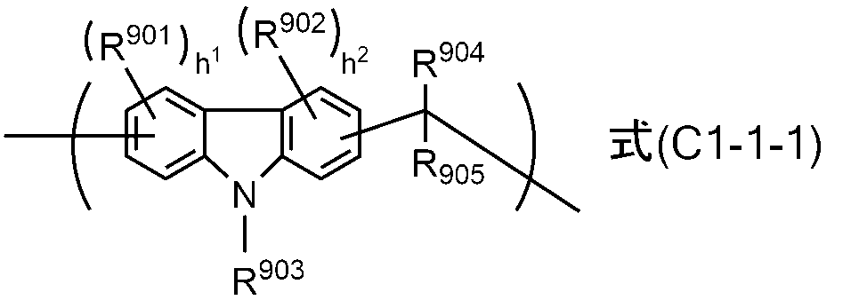
R903は、水素原子、置換されていてもよいアルキル基、置換されていてもよいアルケニル基又は置換されていてもよいアリール基を表す。
R904は、水素原子、置換されていてもよいアリール基又は置換されていてもよいヘテロアリール基を表す。
R905は、置換されていてもよいアルキル基、置換されていてもよいアリール基又は置換されていてもよいヘテロアリール基を表す。
R904の基とR905の基とは、互いに結合して2価の基を形成してもよい。
アルキル基及びアルケニル基の置換基としては、ハロゲン原子、ニトロ基、シアノ基、アミノ基、ヒドロキシ基、カルボキシ基、アリール基、ヘテロアリール基等が挙げられる。
アリール基及びヘテロアリール基の置換基としては、ハロゲン原子、ニトロ基、シアノ基、アミノ基、ヒドロキシ基、カルボキシ基、アルキル基、アルケニル基等が挙げられる。
h1及びh2は、それぞれ独立して、0~3の整数を表す。
置換されていてもよいアリール基及びヘテロアリール基の炭素数は、通常40以下であり、溶解性の観点から、好ましくは30以下、より好ましくは20以下である。
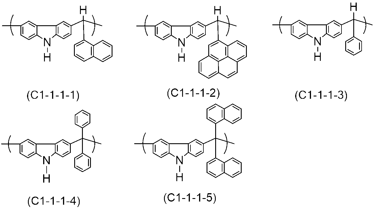
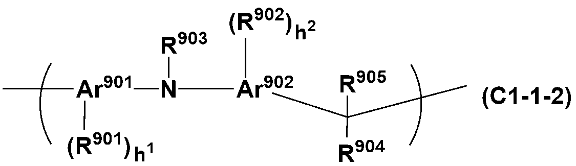
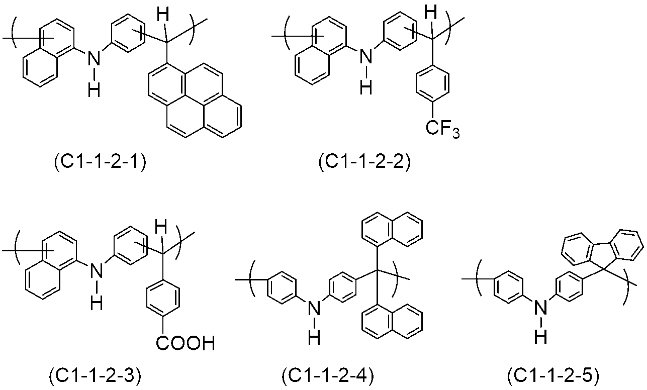
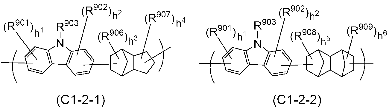
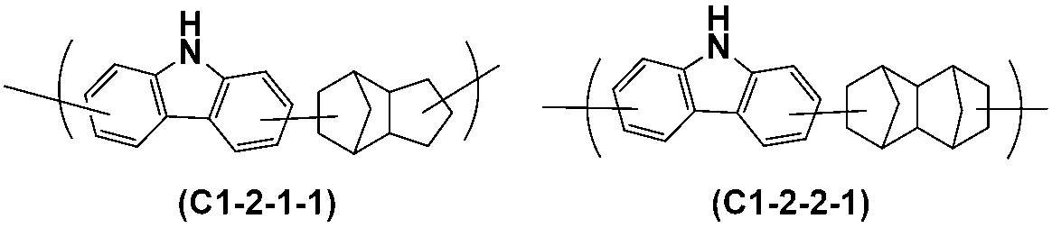
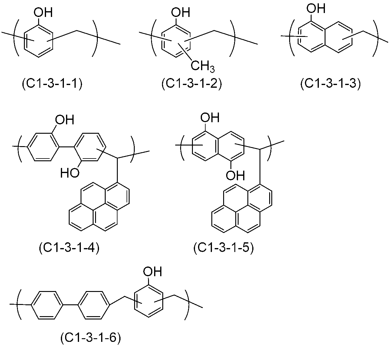
この縮合反応においては、例えば、カルバゾール化合物の環を構成するベンゼン環1当量に対して、通常、アルデヒド化合物又はケトン化合物を0.1~10当量の割合で用いる。
酸触媒としては、例えば硫酸、リン酸、過塩素酸等の鉱酸、p-トルエンスルホン酸、p-トルエンスルホン酸一水和物等の有機スルホン酸、蟻酸、シュウ酸等のカルボン酸が挙げられるが、これらに限定されない。
酸触媒の量は、使用する酸の種類等に応じて適宜決定されるため一概に規定できないが、カルバゾール化合物100質量部に対して、通常0.001~10000質量部の範囲から適宜定められる。
このような溶媒は、反応を阻害しない限り特に限定されるものではないが、典型的には、テトラヒドロフラン、ジオキサン等の環状エーテル化合物等のエーテル化合物が挙げられる。
当業者であれば、上記説明及び技術常識に基づき、過度の負担なく、ノボラック樹脂の製造条件を定めることができ、それ故、ノボラック樹脂を製造することができる。
なお、本発明において、ポリマーであるノボラック樹脂等の有機樹脂の重量平均分子量及び数平均分子量並びに分散度は、例えば、GPC装置(東ソー(株)製EcoSEC,HLC-8320GPC)及びGPCカラム(東ソー(株)TSKgel SuperMultiporeHZ-N, TSKgel SuperMultiporeHZ-H)を用い、カラム温度を40℃とし、溶離液(溶出溶媒)としてテトラヒドロフランを用い、流量(流速)を0.35mL/分とし、標準試料としてポリスチレン(シグマアルドリッチ社製)を用いて、測定することができる。
このようなその他のポリマーとしては、例えば、ポリアクリル酸エステル化合物、ポリメタクリル酸エステル化合物、ポリアクリルアミド化合物、ポリメタクリルアミド化合物、ポリビニル化合物、ポリスチレン化合物、ポリマレイミド化合物、ポリマレイン酸無水物、ポリアクリロニトリル化合物等が挙げられる
剥離剤組成物におけるノボラック樹脂の含有量としては、特に限定されないが、膜構成成分に対して、50~100質量%が好ましい。なお、本発明において、膜構成成分とは、組成物に含まれる溶媒以外の成分を意味する。
多核フェノール誘導体は、例えば、下記式(P)で表される。


上記剥離剤組成物は、分岐鎖状ポリシランを含有していてもよい。
分岐鎖状ポリシランは、Si-Si結合を有し、且つ、枝分かれ構造を有するものである。上記剥離剤組成物に分岐鎖状ポリシランが含まれることで、得られる膜からなる剥離層が、有機溶媒、酸及び半導体素子の製造で用いられる薬液(アルカリ現像液、過酸化水素水等)のいずれによっても好適に除去できないが、洗浄剤組成物によって好適に除去できるものとなり、その結果、本発明で製造される積層体の半導体基板と支持基板を分離した後に各基板を洗浄剤組成物で洗浄することによって、基板上の剥離層の残渣を好適に除去可能となる。この理由は定かではないが、ポリシランの末端基(末端置換基(原子))の種類によっては、ポリシランは有機樹脂と反応して架橋することができ、また、分岐鎖状ポリシランは、直鎖状ポリシランよりも、より多くの末端基(末端置換基(原子))を有することから、分岐鎖状ポリシランは、直鎖状ポリシランよりも、より多くの架橋点を有すると考えられ、分岐鎖状ポリシラン中のこのようなより多くの架橋点を介した適度且つ好適な硬化によって、有機溶媒、酸及び半導体素子の製造で用いられる薬液(アルカリ現像液、過酸化水素水等)によって好適に除去されないという特性と、洗浄剤組成物によって好適に除去されるという特性の両立が実現できるものと推測される。
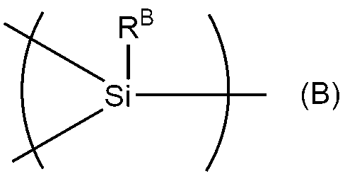
置換されていてもよい直鎖状又は分岐鎖状アルキル基の具体例としては、メチル基、エチル基、n-プロピル基、i-プロピル基、n-ブチル基、i-ブチル基、s-ブチル基、ターシャリーブチル基、n-ペンチル基、1-メチル-n-ブチル基、2-メチル-n-ブチル基、3-メチル-n-ブチル基、1,1-ジメチル-n-プロピル基、1,2-ジメチル-n-プロピル基、2,2-ジメチル-n-プロピル基、1-エチル-n-プロピル基、n-ヘキシル基、1-メチル-n-ペンチル基、2-メチル-n-ペンチル基、3-メチル-n-ペンチル基、4-メチル-n-ペンチル基、1,1-ジメチル-n-ブチル基、1,2-ジメチル-n-ブチル基、1,3-ジメチル-n-ブチル基、2,2-ジメチル-n-ブチル基、2,3-ジメチル-n-ブチル基、3,3-ジメチル-n-ブチル基、1-エチル-n-ブチル基、2-エチル-n-ブチル基、1,1,2-トリメチル-n-プロピル基、1,2,2-トリメチル-n-プロピル基、1-エチル-1-メチル-n-プロピル基、1-エチル-2-メチル-n-プロピル基等が挙げられるが、これらに限定されず、その炭素数は、通常1~14、好ましくは1~10、より好ましくは1~6である。
置換されていてもよい環状アルキル基の具体例としては、シシクロプロピル基、シクロブチル基、1-メチル-シクロプロピル基、2-メチル-シクロプロピル基、シクロペンチル基、1-メチル-シクロブチル基、2-メチル-シクロブチル基、3-メチル-シクロブチル基、1,2-ジメチル-シクロプロピル基、2,3-ジメチル-シクロプロピル基、1-エチル-シクロプロピル基、2-エチル-シクロプロピル基、シクロヘキシル基、1-メチル-シクロペンチル基、2-メチル-シクロペンチル基、3-メチル-シクロペンチル基、1-エチル-シクロブチル基、2-エチル-シクロブチル基、3-エチル-シクロブチル基、1,2-ジメチル-シクロブチル基、1,3-ジメチル-シクロブチル基、2,2-ジメチル-シクロブチル基、2,3-ジメチル-シクロブチル基、2,4-ジメチル-シクロブチル基、3,3-ジメチル-シクロブチル基、1-n-プロピル-シクロプロピル基、2-n-プロピル-シクロプロピル基、1-i-プロピル-シクロプロピル基、2-i-プロピル-シクロプロピル基、1,2,2-トリメチル-シクロプロピル基、1,2,3-トリメチル-シクロプロピル基、2,2,3-トリメチル-シクロプロピル基、1-エチル-2-メチル-シクロプロピル基、2-エチル-1-メチル-シクロプロピル基、2-エチル-2-メチル-シクロプロピル基、2-エチル-3-メチル-シクロプロピル基等のシクロアルキル基、ビシクロブチル基、ビシクロペンチル基、ビシクロヘキシル基、ビシクロヘプチル基、ビシクロオクチル基、ビシクロノニル基、ビシクロデシル基等のビシクロアルキル基等が挙げられるが、これらに限定されず、その炭素数は、通常3~14、好ましくは4~10、より好ましくは5~6である。
置換されていてもよい直鎖状又は分岐鎖状アルケニル基の具体例としては、ビニル基、アリル基、ブテニル基、ペンテニル基等が挙げられるが、これらに限定されず、その炭素数は、通常2~14、好ましくは2~10、より好ましくは1~6である。
置換されていてもよい環状アルケニル基の具体例としては、シクロペンテニル、シクロヘキセニル等が挙げられるが、これらに限定されず、その炭素数は、通常4~14、好ましくは5~10、より好ましくは5~6である。
置換されていてもよい直鎖状又は分岐鎖状アルコキシ基の具体例としては、メトキシ基、エトキシ基、プロポキシ基、イソプロポキシ基、ブトキシ基、t-ブトキシ基、ペンチルオキシ基等が挙げられるが、これらに限定されず、その炭素数は、通常1~14、好ましくは1~10、より好ましくは1~6である。
置換されていてもよい環状アルコキシ基の具体例としては、シクロペンチルオキシ、シクロヘキシルオキシ等が挙げられるが、これらに限定されず、その炭素数は、通常3~14、好ましくは4~10、より好ましくは5~6である。

ある態様においては、分岐鎖状ポリシランの重量平均分子量の上限値は、通常30,000、好ましくは20,000、より好ましくは10,000、より一層好ましくは5,000、更に好ましくは2,000、更に一層好ましくは1,500であり、その下限値は、通常50、好ましくは100、より好ましくは150、より一層好ましくは200、更に好ましくは300、更に一層好ましくは500である。
分岐鎖状ポリシランの平均重合度及び重量平均分子量は、例えば、GPC装置(東ソー(株)製EcoSEC,HLC-8220GPC)及びGPCカラム(昭和電工(株)製 Shodex KF-803L、KF-802及びKF-801をこの順序で使用)を用い、カラム温度を40℃とし、溶離液(溶出溶媒)としてテトラヒドロフランを用い、流量(流速)を1.00mL/分とし、標準試料としてポリスチレン(シグマアルドリッチ社製)を用いて、測定することができる。
用いる分岐鎖状ポリシランの重合度及び重量平均分子量が小さすぎると、剥離層である膜を形成する際や得られた剥離層を備える積層体に対する加工が施される際等の加熱によって分岐鎖状ポリシランが気化したり、膜の強度不良による不具合が生じたりする可能性があり、用いる分岐鎖状ポリシランの重合度及び分子量が大きすぎると、剥離剤組成物の調製に用いる溶媒の種類によっては十分な溶解性が確保できずに組成物中で析出が生じたり、樹脂との混合が不十分となって均一性の高い膜を再現性よく得られない可能性がある。
それ故、半導体素子の好適な製造に寄与する剥離層を備える積層体をより一層再現性よく得る観点からは、分岐鎖状ポリシランの重合度及び重量平均分子量は上述の範囲を満たすことが望ましい。
分岐鎖状ポリシランの5%重量減少温度は、例えば、NETZSCH社製 2010SRを用いて、空気下で、常温(25℃)から400℃まで10℃/分で昇温することで、測定することができる。
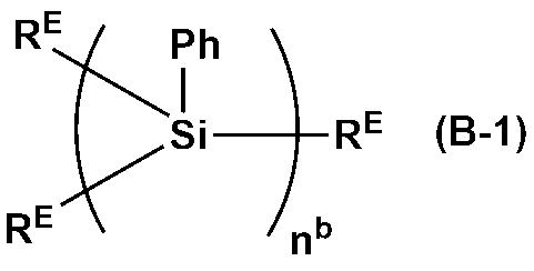
剥離剤組成物は、架橋剤を含んでもよい。
架橋剤は自己縮合による架橋反応を起こすこともあるが、ノボラック樹脂中に架橋性置換基が存在する場合は、それらの架橋性置換基と架橋反応を起こすことができる。
剥離剤組成物が含む架橋剤は、通常、2個以上の架橋形成基を有するが、より好適な硬化を再現性よく実現する観点から、架橋剤である化合物に含まれる架橋形成基の数は、好ましくは2~10、より好ましくは2~6である。
剥離剤組成物が含む架橋剤は、より高い耐熱性を実現する観点からは、好ましくは分子内に芳香族環(例えば、ベンゼン環、ナフタレン環)を有し、そのような架橋剤の典型例としては、これに限定されるものではないが、フェノール系架橋剤が挙げられる。
架橋形成基が結合する芳香族環とフェノール性ヒドロキシ基及び/又はフェノール性ヒドロキシ基から誘導されるアルコキシ基が結合する芳香族環はいずれも、ベンゼン環等の非縮環型芳香族環に限られず、ナフタレン環、アントラセン等の縮環型芳香族環であってもよい。
フェノール系架橋剤の分子内に芳香族環が複数存在する場合、架橋形成基とフェノール性ヒドロキシ基及びフェノール性ヒドロキシ基から誘導されるアルコキシ基とは、分子内の同じ芳香族環に結合していてもよく、異なる芳香族環に結合していてもよい。
架橋形成基やフェノール性ヒドロキシ基及びフェノール性ヒドロキシ基から誘導されるアルコキシ基が結合する芳香族環は、メチル基、エチル基、ブチル基等のアルキル基、フェニル基等のアリール基等の炭化水素基、フッ素原子等のハロゲン原子等で更に置換されていてもよい。


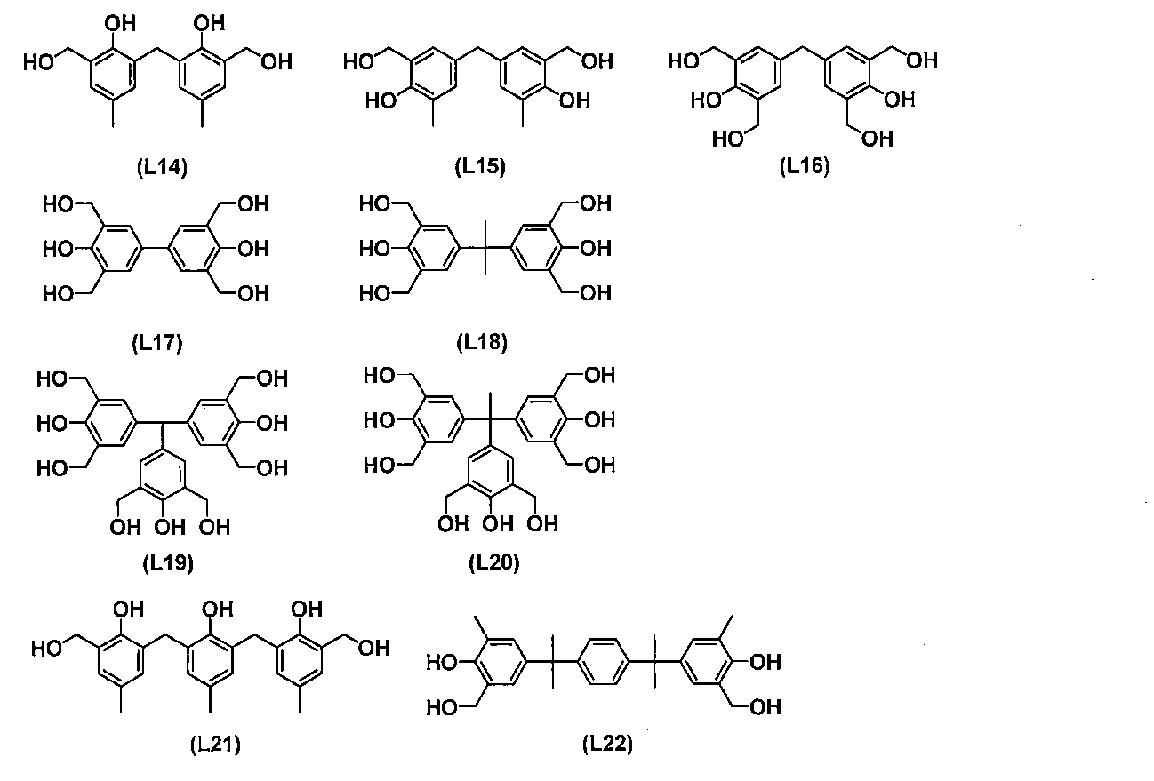
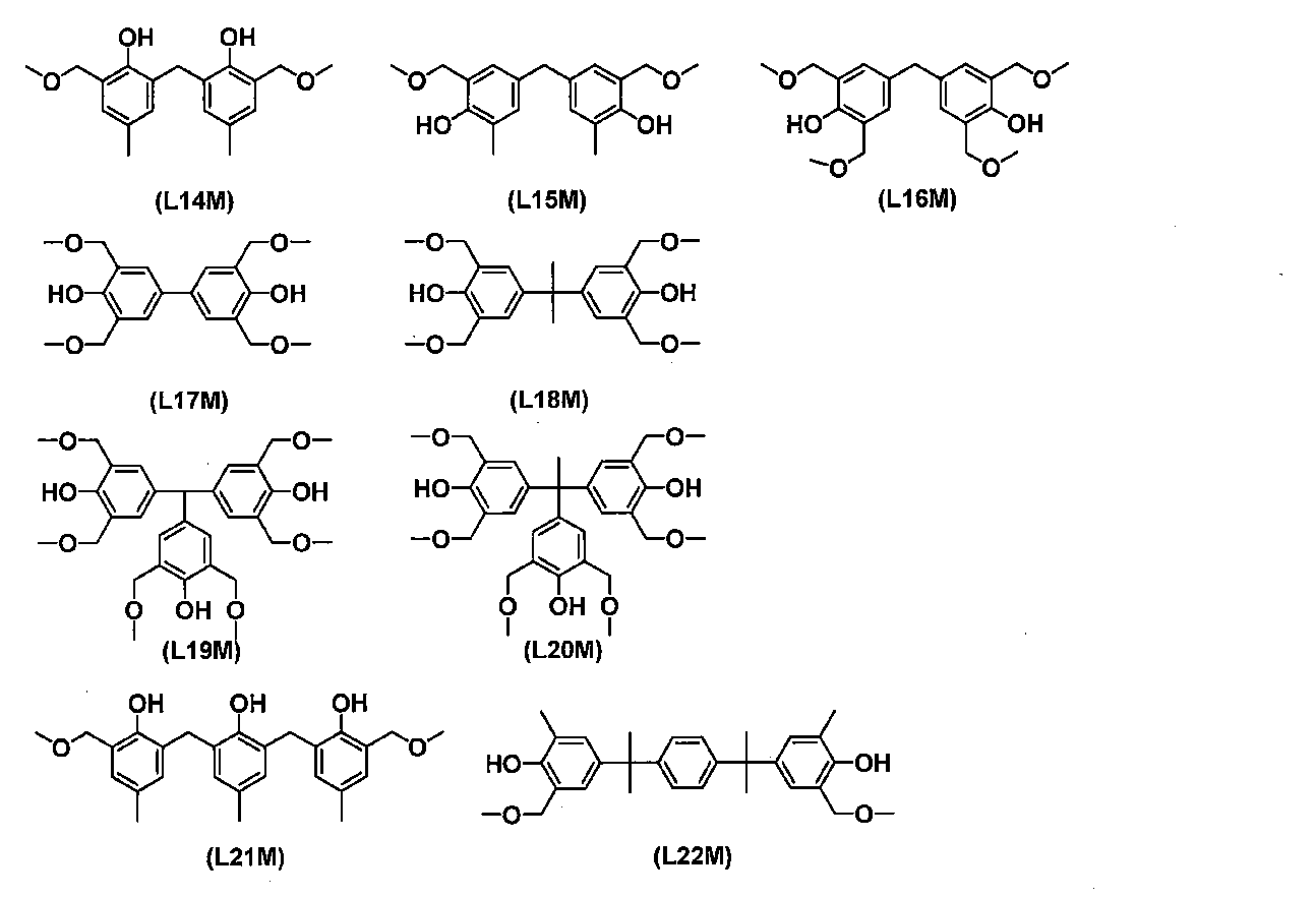
架橋形成基を有するメラミン系架橋剤の具体例としては、N,N,N’,N’,N”,N”-ヘキサキス(メトキシメチル)メラミン、N,N,N’,N’,N”,N”-ヘキサキス(ブトキシメチル)メラミン等のモノ、ビス、トリス、テトラキス、ペンタキス又はヘキサキスアルコキシメチルメラミン、N,N,N’,N’-テトラキス(メトキシメチル)ベンゾグアナミン、N,N,N’,N’-テトラキス(ブトキシメチル)ベンゾグアナミン等のモノ、ビス、トリス又はテトラキスアルコキシメチルベンゾグアナミン等が挙げられるが、これらに限定されない。
架橋形成基を有する尿素系架橋剤の具体例としては、1,3,4,6-テトラキス(メトキシメチル)グリコールウリル、1,3,4,6-テトラキス(ブトキシメチル)グリコールウリル等のモノ、ビス、トリス又はテトラキスアルコキシメチルグリコールウリル、1,3-ビス(メトキシメチル)尿素、1,1,3,3-テトラキスメトキシメチル尿素等のモノ、ビス、トリス又はテトラキスアルコキシメチル尿素等が挙げられるが、これらに限定されない。
架橋形成基を有するチオ尿素系架橋剤の具体例としては、1,3-ビス(メトキシメチル)チオ尿素、1,1,3,3-テトラキスメトキシメチルチオ尿素等のモノ、ビス、トリス又はテトラキスアルコキシメチルチオ尿素等が挙げられるが、これらに限定されない。
架橋反応の促進等を目的として、剥離剤組成物は、酸発生剤や酸を含んでもよい。
熱酸発生剤は、熱により酸を発生する限り特に限定されるものではなく、その具体例としては、2,4,4,6-テトラブロモシクロヘキサジエノン、ベンゾイントシレート、2-ニトロベンジルトシレート、K-PURE〔登録商標〕CXC-1612、同CXC-1614、同TAG-2172、同TAG-2179、同TAG-2678、同TAG2689、同TAG2700(King Industries社製)、及びSI-45、SI-60、SI-80、SI-100、SI-110、SI-150(三新化学工業(株)製)その他有機スルホン酸アルキルエステル等が挙げられるが、これらに限定されない。
剥離剤組成物は、組成物自体の液物性や得られる膜の膜物性を調整することや、均一性の高い剥離剤組成物を再現性よく調製すること等を目的として、界面活性剤を含んでもよい。
界面活性剤としては、例えばポリオキシエチレンラウリルエーテル、ポリオキシエチレンステアリルエーテル、ポリオキシエチレンセチルエーテル、ポリオキシエチレンオレイルエーテル等のポリオキシエチレンアルキルエーテル類、ポリオキシエチレンオクチルフエノールエーテル、ポリオキシエチレンノニルフエノールエーテル等のポリオキシエチレンアルキルアリルエーテル類、ポリオキシエチレン・ポリオキシプロピレンブロツクコポリマー類、ソルビタンモノラウレート、ソルビタンモノパルミテート、ソルビタンモノステアレート、ソルビタンモノオレエート、ソルビタントリオレエート、ソルビタントリステアレート等のソルビタン脂肪酸エステル類、ポリオキシエチレンソルビタンモノラウレート、ポリオキシエチレンソルビタンモノパルミテート、ポリオキシエチレンソルビタンモノステアレート、ポリオキシエチレンソルビタントリオレエート、ポリオキシエチレンソルビタントリステアレート等のポリオキシエチレンソルビタン脂肪酸エステル類等のノニオン系界面活性剤、エフトツプEF301、EF303、EF352((株)トーケムプロダクツ製、商品名)、メガファックF171、F173、R-30、R-30N(DIC(株)製、商品名)、フロラードFC430、FC431(住友スリーエム(株)製、商品名)、アサヒガードAG710、サーフロンSー382、SC101、SC102、SC103、SC104、SC105、SC106(旭硝子(株)製、商品名)等のフッ素系界面活性剤、オルガノシロキサンポリマーKP341(信越化学工業(株)製)等を挙げることができる。
界面活性剤は、一種単独で又は2種以上組み合わせて用いることができる。
界面活性剤の量は、剥離剤組成物の膜構成成分に対して、通常2質量%以下である。
剥離剤組成物は、好ましくは溶媒を含む。
このような溶媒としては、例えば、前述の有機樹脂、多核フェノール誘導体、分岐鎖状ポリシラン、架橋剤等の膜構成成分を良好に溶解できる高極性溶媒を用いることができ、必要に応じて、粘度、表面張力等の調整等を目的に、低極性溶媒を用いてもよい。なお、本発明において、低極性溶媒とは周波数100kHzでの比誘電率が7未満のものを、高極性溶媒とは周波数100kHzでの比誘電率が7以上のものと定義する。溶媒は、1種単独で又は2種以上組み合わせて用いることができる。
プロピレングリコールモノメチルエーテル、ジエチレングリコールモノメチルエーテル、ジエチレングリコールモノフェニルエーテル、トリエチレングリコールモノメチルエーテル、ジプロピレングリコールモノメチルエーテル、ベンジルアルコール、2-フェノキシエタノール、2-ベンジルオキシエタノール、3-フェノキシベンジルアルコール、テトラヒドロフルフリルアルコール等の脂肪族アルコール以外の1価アルコール系溶媒;ジメチルスルホキシド等のスルホキシド系溶媒等が挙げられる。
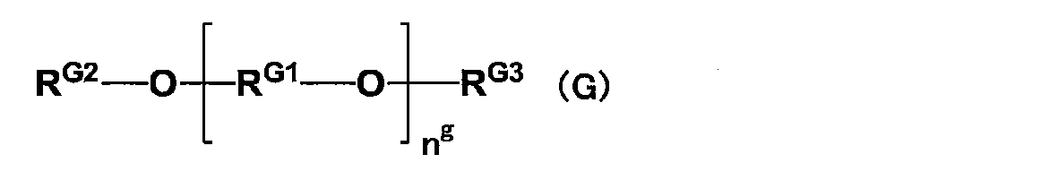
中でも、均一性の高い組成物を再現性よく得る観点、保存安定性の高い組成物を再現性よく得る観点、均一性の高い膜を与える組成物を再現性よく得る観点等から、炭素数2~3の直鎖状又は分岐鎖状アルキレン基が好ましく、炭素数3の直鎖状又は分岐鎖状アルキレン基がより好ましい。
中でも、均一性の高い組成物を再現性よく得る観点、保存安定性の高い組成物を再現性よく得る観点、均一性の高い膜を与える組成物を再現性よく得る観点等から、メチル基、エチル基が好ましく、メチル基がより好ましい。
中でも、均一性の高い組成物を再現性よく得る観点、保存安定性の高い組成物を再現性よく得る観点、均一性の高い膜を与える組成物を再現性よく得る観点等から、メチルカルボニル基、エチルカルボニル基が好ましく、メチルカルボニル基がより好ましい。
均一性の高い組成物を再現性よく得る観点、保存安定性の高い組成物を再現性よく得る観点、均一性の高い膜を与える組成物を再現性よく得る観点等から、剥離剤組成物においては、膜構成成分は、溶媒に均一に分散又は溶解しており、好ましくは溶解している。
その混合順序は特に限定されるものではないが、容易にかつ再現性よく剥離剤組成物を製造できる方法の一例としては、有機樹脂又は多核フェノール誘導体と、架橋剤を一度に溶媒に溶解させる方法や、有機樹脂又は多核フェノール誘導体、及び架橋剤の一部を溶媒に溶解させ、残りを溶媒に別途溶解させ、得られた各溶液を混合する方法が挙げられるが、これらに限定されない。また、剥離剤組成物を調製する際、成分が分解したり変質したりしない範囲で、適宜加熱してもよい。
本発明においては、異物を除去する目的で、剥離剤組成物を製造する途中で又は全ての成分を混合した後に、用いる溶媒や溶液等をフィルター等を用いてろ過してもよい。
第1の接着剤組成物及び第2の接着剤組成物は、前述のとおり、以下の(1)又は(2)を満たす。
(1):第1の接着剤組成物は、第1の熱硬化成分と、触媒存在下で第1の熱硬化成分と反応する第2の熱硬化成分とを含有する。第2の接着剤組成物は、触媒を含有する。
(2):第2の接着剤組成物は、第1の熱硬化成分と、触媒存在下で第1の熱硬化成分と反応する第2の熱硬化成分とを含有する。第1の接着剤組成物は、触媒を含有する。
第1の接着剤組成物又は第2の接着剤組成物である触媒含有組成物は、触媒を少なくとも含有し、更に必要に応じて、溶媒などのその他の成分を含有する。
触媒含有組成物は、第1の熱硬化成分及び第2の熱硬化成分のいずれかを含有していてもよい。
触媒含有組成物が、第1の熱硬化成分を含有する場合、触媒含有組成物に含有される第1の熱硬化成分は、第1の熱硬化成分である限り、特に制限されず、熱硬化成分含有組成物に含有される第1の熱硬化成分と同じ熱硬化成分であってもよいし、異なる熱硬化成分であってもよい。
触媒含有組成物が、第2の熱硬化成分を含有する場合、触媒含有組成物に含有される第2の熱硬化成分は、第2の熱硬化成分である限り、特に制限されず、熱硬化成分含有組成物に含有される第2の熱硬化成分と同じ熱硬化成分であってもよいし、異なる熱硬化成分であってもよい。
接着剤組成物のキットは、第1の接着剤組成物及び第2の接着剤組成物を含有する。
第1の接着剤組成物は、第1の接着剤塗布層の形成に用いられる。
第2の接着剤組成物は、第2の接着剤塗布層の形成に用いられる。
第1の熱硬化成分及び第2の熱硬化成分は、触媒存在下で好適に反応する熱硬化成分であれば、特に限定されない。
なお、第1の熱硬化成分及び第2の熱硬化成分は、触媒不存在下で反応する熱硬化成分であってもよい。
第1の熱硬化成分に含まれるアルケニル基と、第2の熱硬化成分に含まれる水素原子(Si-H基)とが白金族金属系触媒(A2)によるヒドロシリル化反応によって架橋構造を形成し硬化する。その結果、硬化膜が形成される。
第2の熱硬化成分は、Si-H基を有するポリオルガノシロキサン(a2)を含有することが好ましい。
ここで、炭素数2~40のアルケニル基は置換されていてもよい。置換基としては、例えば、ハロゲン原子、ニトロ基、シアノ基、アミノ基、ヒドロキシ基、カルボキシ基、アリール基、ヘテロアリール基等が挙げられる。
ケイ素原子に結合した炭素数2~40のアルケニル基を有するポリオルガノシロキサン(a1)の一例は、SiO2で表されるシロキサン単位(Q’単位)、R1’R2’R3’SiO1/2で表されるシロキサン単位(M’単位)、R4’R5’SiO2/2で表されるシロキサン単位(D’単位)及びR6’SiO3/2で表されるシロキサン単位(T’単位)からなる群より選ばれる1種又は2種以上の単位を含むとともに、M’単位、D’単位及びT’単位からなる群より選ばれる少なくとも1種を含むポリオルガノシロキサン(a1’)である。
Si-H基を有するポリオルガノシロキサン(a2)の一例は、SiO2で表されるシロキサン単位(Q”単位)、R1”R2”R3”SiO1/2で表されるシロキサン単位(M”単位)、R4”R5”SiO2/2で表されるシロキサン単位(D”単位)及びR6”SiO3/2で表されるシロキサン単位(T”単位)からなる群より選ばれる1種又は2種以上の単位を含むとともに、M”単位、D”単位及びT”単位からなる群より選ばれる少なくとも1種を含むポリオルガノシロキサン(a2’)である。
置換されていてもよい環状アルケニル基の具体例としては、シクロペンテニル、シクロヘキセニル等が挙げられるが、これらに限定されず、その炭素数は、通常4~14であり、好ましくは5~10、より好ましくは5~6である。
なお、本発明において、ポリオルガノシロキサンの重量平均分子量及び数平均分子量並びに分散度は、例えば、GPC装置(東ソー(株)製EcoSEC,HLC-8320GPC)及びGPCカラム(東ソー(株)TSKgel SuperMultiporeHZ-N, TSKgel SuperMultiporeHZ-H)を用い、カラム温度を40℃とし、溶離液(溶出溶媒)としてテトラヒドロフランを用い、流量(流速)を0.35mL/分とし、標準試料としてポリスチレン(昭和電工(株)製、Shodex)を用いて、測定することができる。
このような白金系の金属触媒は、ポリオルガノシロキサン(a1)のアルケニル基とポリオルガノシロキサン(a2)のSi-H基とのヒドロシリル化反応を促進するための触媒である。
白金とオレフィン類との錯体としては、例えばジビニルテトラメチルジシロキサンと白金との錯体が挙げられるが、これに限定されない。
触媒含有組成物に含有される白金族金属系触媒(A2)の量は、特に限定されないが、通常、第1の接着層塗布層及び第2の接着剤塗布層の合計における、ポリオルガノシロキサン(a1)及びポリオルガノシロキサン(a2)の合計量に対して、1.0~50.0ppmの範囲である。
熱硬化成分含有組成物及び触媒含有組成物は、粘度の調整等を目的に、溶媒を含んでいてもよく、その具体例としては、脂肪族炭化水素、芳香族炭化水素、ケトン等が挙げられるが、これらに限定されない。
触媒含有組成物は、その他の成分として、ポリオルガノシロキサン以外の重合体を含有していてもよい。そのような重合体としては、例えば、熱可塑性樹脂が挙げられる。
スチレン系エラストマーとしては、例えば、スチレン-エチレン-ブチレン-スチレンブロック共重合体(SEBS)、スチレン-エチレン-プロピレン-スチレンブロック共重合体(SEPS)、スチレン-エチレン-エチレン-プロピレン-スチレンブロック共重合体(SEEPS)、スチレン-ブタジエンゴム(SBR)、アクリロニトリル-ブタジエンゴム(NBR)、ピリジン-ブタジエンゴム、スチレン-イソプレンゴム(SIR)、スチレン-エチレン共重合体、ポリスチレン-ポリブタジエン-ポリスチレン(SBS)、ポリスチレン-ポリイソプレン-ポリスチレン(SIS)、ポリ(α-メチルスチレン)-ポリブタジエン-ポリ(α-メチルスチレン)(α-MeSBα-MeS)、ポリ(α-メチルスチレン)-ポリイソプレン-ポリ(α-メチルスチレン)、エチレン-プロピレン共重合体(EP)、スチレン-クロロプレンゴム(SCR)、スチレン-ブタジエン-スチレン(SBS)共重合体、スチレン-イソプレン-スチレン(SIS)共重合体、スチレン-ポリイソプレンエラストマー、スチレン-ポリブタジエンエラストマー、スチレン-ポリイソプレン-ブタジエンランダムコポリマーなどが挙げられる。
エチレン-アクリレート共重合体としては、例えば、エチレン-メチルアクリレート共重合体、エチレン-エチルアクリレート共重合体、エチレン-ブチルアクリレート共重合体などが挙げられる。
これらは、一部又は全部が水素添加されていてもよい。
剥離層及び接着層形成工程は、第1の接着剤塗布層と第2の接着剤塗布層との貼り合せ及び加熱が行われ、剥離剤塗布層から剥離層が形成され、第1の接着剤塗布層及び第2の接着剤塗布層から接着層が形成される工程である。
後加熱の時間は、積層体を構成する基板及び層の好適な接合を実現する観点から、通常1分以上、好ましくは5分以上であり、過度の加熱による各層への悪影響等を抑制又は回避する観点から、通常180分以下、好ましくは120分以下である。
加熱は、ホットプレート、オーブン等を用いて行うことができる。ホットプレートを用いて後加熱をする場合、積層体の半導体基板と支持基板のいずれを下にして加熱してもよいが、好適な剥離を再現性よく実現する観点から、半導体基板を下にして後加熱することが好ましい。
なお、後加熱処理の一つの目的は、より好適な自立膜である接着層と剥離層を実現することであり、第1の熱硬化成分及び第2の熱硬化成分による熱硬化(特にヒドロシリル化反応による硬化)を好適に実現することである。
まず、表面に剥離剤塗布層3Aが形成された支持基板4を用意する。そして、剥離剤塗布層3Aの表面に第1の接着剤塗布層2Aを形成する(図1)。第1の接着剤塗布層2Aは、第1の接着剤組成物から形成される。接着剤塗布層2Aは、例えば、剥離剤塗布層3Aの表面に第1の接着剤組成物を塗布することにより形成される。
次に、半導体基板1の表面に第2の接着剤塗布層2Bを形成する(図2)。第2の接着剤塗布層2Bは、第2の接着剤組成物から形成される。第2の接着剤塗布層2Bは、例えば、半導体基板1の表面に第2の接着剤組成物を塗布することにより形成される。
次に、第1の接着剤塗布層2Aと第2の接着剤塗布層2Bとを貼り合せ、加熱する(図3)。そうすると、剥離剤塗布層3Aから剥離層3が形成され、かつ第1の接着剤塗布層2A及び第2の接着剤塗布層2Bが一体となって接着層2が形成される。その結果、半導体基板1と接着層2と剥離層3と支持基板4とを有する積層体が得られる(図4)。
本発明の加工された半導体基板の製造方法は、第1工程と、第2工程とを少なくとも含み、更に必要に応じて、第3工程などのその他の工程を含む。
第1工程は、本発明の積層体の製造方法によって製造された積層体の半導体基板が加工される工程である。
第2工程は、第1工程によって加工された半導体基板と支持基板とが分離される工程である。第2工程は、剥離層に対して光が照射される工程を含む。
第3工程は、分離された半導体基板が、洗浄剤組成物で洗浄される工程である。
なお、加工は、上述したものに限定されず、例えば、半導体部品を実装するための基材をサポートするために支持基板と仮接着した場合の半導体部品の実装プロセスの実施等も含まれる。
支持基板側から剥離層に光を照射することによって、上述の通りに剥離層の変質(例えば、剥離層の分離又は分解)を生じさせ、その後、例えば、いずれか一方の基板を引き上げて、容易に、半導体基板と支持基板とを分離することができる。そのため、第2工程では、鋭部を有する機材による機械的な剥離を用いずとも半導体基板と支持基板とを分離(剥離)することができる。
通常、剥離のための光の照射量は、50~3,000mJ/cm2である。照射時間は、波長及び照射量に応じて適宜決定される。
光の照射は、レーザー光を用いて行ってもよく、紫外線ランプ等の光源からの非レーザー光で用いて行ってもよい。
洗浄剤組成物の好適な一例としては、第四級アンモニウム塩と、溶媒とを含む洗浄剤組成物が挙げられる。
第四級アンモニウム塩は、第四級アンモニウムカチオンと、アニオンとから構成されるものであって、この種の用途に用いられるものであれば特に限定されるものではない。
このような第四級アンモニウムカチオンとしては、典型的には、テトラ(炭化水素)アンモニウムカチオンが挙げられる。一方、それと対を成すアニオンとしては、水酸化物イオン(OH-);フッ素イオン(F-)、塩素イオン(Cl-)、臭素イオン(Br-)、ヨウ素イオン(I-)等のハロゲンイオン;テトラフルオロホウ酸イオン(BF4 -);ヘキサフルオロリン酸イオン(PF6 -)等が挙げられるが、これらに限定されない。
第四級アンモニウム塩中、ハロゲン原子は、カチオンに含まれていても、アニオンに含まれていてもよいが、好ましくはアニオンに含まれる。
フッ化テトラ(炭化水素)アンモニウムにおける炭化水素基の具体例としては、炭素数1~20のアルキル基、炭素数2~20のアルケニル基、炭素数2~20のアルキニル基、炭素数6~20のアリール基等が挙げられる。
より好ましい一態様においては、フッ化テトラ(炭化水素)アンモニウムは、フッ化テトラアルキルアンモニウムを含む。
フッ化テトラアルキルアンモニウムの具体例としては、フッ化テトラメチルアンモニウム、フッ化テトラエチルアンモニウム、フッ化テトラプロピルアンモニウム、フッ化テトラブチルアンモニウム(テトラブチルアンモニウムフルオリドともいう)等が挙げられるが、これらに限定されない。中でも、フッ化テトラブチルアンモニウムが好ましい。
第四級アンモニウム塩の量は、洗浄剤組成物に含まれる溶媒に溶解する限り特に制限されるものではないが、洗浄剤組成物に対して、通常0.1~30質量%である。

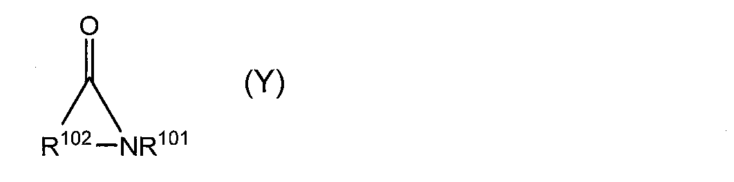
このようなその他の有機溶媒は、この種の用途に用いられるものであって、上述のアミド化合物と相溶性がある有機溶媒であれば特に限定されるものではない。
好ましいその他の溶媒としては、アルキレングリコールジアルキルエーテル、芳香族炭化水素化合物、環状構造含有エーテル化合物等が挙げられるが、これらに限定されない。
上述のアミド化合物とは異なるその他の有機溶媒の量は、洗浄剤組成物に含まれる第四級アンモニウム塩が析出又は分離せず、かつ上述のアミド化合物と均一に混ざり合う限りにおいて、通常、洗浄剤組成物に含まれる溶媒中95質量%以下で適宜決定される。
なお、洗浄剤組成物は、溶媒として、水を含んでもよいが、基板の腐食等を回避する観点等から、通常、有機溶媒のみが、溶媒として意図して用いられる。なお、この場合において、塩の水和水や、有機溶媒に含まれる微量含まれる水が、洗浄剤組成物に含まれてしまうことまでもが、否定される訳ではない。洗浄剤組成物の含水量は、通常5質量%以下である。
本発明の加工された半導体基板の製造方法は、上述の工程以外の工程を含んでもよい。
(2)真空貼り合わせ装置:ズースマイクロテック(株)製 XBS300
(3)高剛性研削盤:(株)東京精密製 HRG300
(4)光学式膜厚計(膜厚測定):フィルメトリクス(株)製 F-50
(5)レーザー照射装置:コヒレント(株)製 Lambda SX
[調製例1]
撹拌機専用600mL容器に、ポリシロキサン骨格とビニル基とを含有するMQ樹脂(ワッカーケミ社製)34.6g、粘度100mPa・sのSiH基含有直鎖状ポリジメチルシロキサン(ワッカーケミ社製)5.34g、粘度200mPa・sのビニル基含有直鎖状ポリジメチルシロキサン(ワッカーケミ社製)21.8g、及びp-メンタン(日本テルペン化学(株)製)18.75gを入れ、撹拌機で5分間撹拌し、混合物を得た。
得られた混合物をナイロンフィルター300メッシュでろ過し、接着剤組成物-1を得た。
撹拌機専用600mL容器に、ポリシロキサン骨格とビニル基とを含有するMQ樹脂(ワッカーケミ社製)12.5g、白金触媒(ワッカーケミ社製)2.5g、粘度1,000mPa・sのビニル基含有直鎖状ポリジメチルシロキサン(ワッカーケミ社製)25g、及びn-ノナン(東京化成工業(株)製)25gを入れ、撹拌機で5分間撹拌し、混合物を得た。
得られた混合物をナイロンフィルター300メッシュでろ過し、接着剤組成物-2を得た。
撹拌機専用600mL容器に、SEPTON4055(クラレ社製、スチレンエチレンエチレンプロピレンスチレンブロック共重合体(SEEPS))7.5g、白金触媒(ワッカーケミ社製)0.375g、及びメシチレン(東京化成工業(株)製)99.64gを入れ、撹拌機で5分間撹拌し、混合物を得た。
得られた混合物をナイロンフィルター300メッシュでろ過し、接着剤組成物-3を得た。
[合成例1]
フラスコ内に、N-フェニル-1-ナフチルアミン56.02g、1-ピレンカルボキシアルデヒド50.00g、4-(トリフルオロメチル)ベンズアルデヒド6.67g、及びメタンスルホン酸2.46gを入れ、そこへ1,4-ジオキサン86.36g、及びトルエン86.36gを加え、窒素雰囲気下で18時間還流撹拌した。
得られた反応混合物を放冷した後、テトラヒドロフラン96gを加えて希釈し、得られた希釈液をメタノール中に滴下させることで沈殿物を得た。得られた沈殿物をろ過で回収し、ろ物をメタノールで洗浄し、60℃で減圧乾燥することで、ノボラック樹脂(以下、PPNAPCA-Fと略称する)72.12gを得た。以下の方法で測定した結果、ポリマーであるノボラック樹脂の重量平均分子量は1,100であった。
PPNAPCA-Fの重量平均分子量は、GPC装置(東ソー(株)製EcoSEC,HLC-8220GPC)及びGPCカラム(昭和電工(株)製 Shodex KF-803L、KF-802及びKF-801をこの順序で使用)を用い、カラム温度を40℃とし、溶離液(溶出溶媒)としてテトラヒドロフランを用い、流量(流速)を1.00mL/分とし、標準試料としてポリスチレン(シグマアルドリッチ社製)を用いて、測定した。
[調製例4]
合成例1で得られたノボラック樹脂3.6g、架橋剤として3,3’,5,5’-テトラキス(メトキシメチル)-[1,1’-ビフェニル]-4,4’-ジオール0.72g、及びピリジニウムパラトルエンスルホネート0.1gをプロピレングリコールモノメチルエーテルアセテート95.58gに溶解させ、得られた溶液を孔径0.2μmのポリエチレン製ミクロフィルターを用いてろ過し、剥離剤組成物を得た。
[実施例1]
調製例4で得られた剥離剤組成物を、キャリア側の基板としての301mmのガラスウエハー(EAGLE-XG、コーニング社製、厚さ700μm)にスピンコートし、250℃5分間ホットプレート上で焼成し、最終的に得られる積層体中の膜厚が200nmとなるように支持基板であるガラスウエハー上に剥離剤塗布層を形成した。
剥離剤塗布層上に接着剤組成物-1を、スピンコートした後に120℃90秒間ホットプレート上で加熱し、最終的に得られる積層体中の膜厚が30μmとなる様に接着剤塗布層-1を形成した。
一方、調製例2で得られた接着剤組成物-2を、デバイス側の基板としての300mmのシリコンウエハー(厚さ775μm)にスピンコートした後に120℃90秒間ホットプレート上で加熱し、最終的に得られる積層体中の膜厚が5μmとなる様に半導体基板であるシリコンウエハー上に接着剤塗布層-2を形成した。
そして、貼り合せ装置を用いて、二枚のウエハーを、接着剤塗布層-1及び接着剤塗布層-2を挟み込むように貼り合わせた後、200℃10分間の後加熱処理をすることにより積層体を作製した。なお、貼り合せは、温度23℃、減圧度1,500Paで行った。なお、積層体は、必要な数だけ製造した。
得られた積層体のシリコンウエハーを高剛性研削盤で50μmまで薄化した後、積層体を、薄化したシリコンウエハー側を下にしてダイシングテープ(日東電工(株)製、DU-300)に貼り付け、固定した。
レーザー照射装置を用いて、波長308nmのレーザーを、固定した積層体のガラスウエハー側から剥離層に200mJ/cm2で照射し、剥離が生じた最も低い照射量を最適照射量とした。そして、最適照射量にて波長308nmのレーザーを、固定した積層体のガラスウエハー側から剥離層全面に照射し、支持基板をマニュアルで持ち上げることによって、剥離可否を確認した結果と、剥離後の接着剤層(接着層)が硬化しているか確認した結果を表1に示す。接着剤層の硬化性の確認は指で触れた際のタック性の有無を確認した。
接着剤組成物-2の代わりに接着剤組成物-3を用いた以外は実施例1と同様の手順で検討を実施した。評価結果を表1に示す。
剥離剤塗布層を形成せずにキャリア側基板に接着剤組成物-1を塗布した以外は実施例1と同様の手順で検討を実施した。評価結果を表1に示す。
剥離剤塗布層を形成せずにキャリア側基板に接着剤組成物-1を塗布した以外は実施例2と同様の手順で検討を実施した。評価結果を表1に示す。
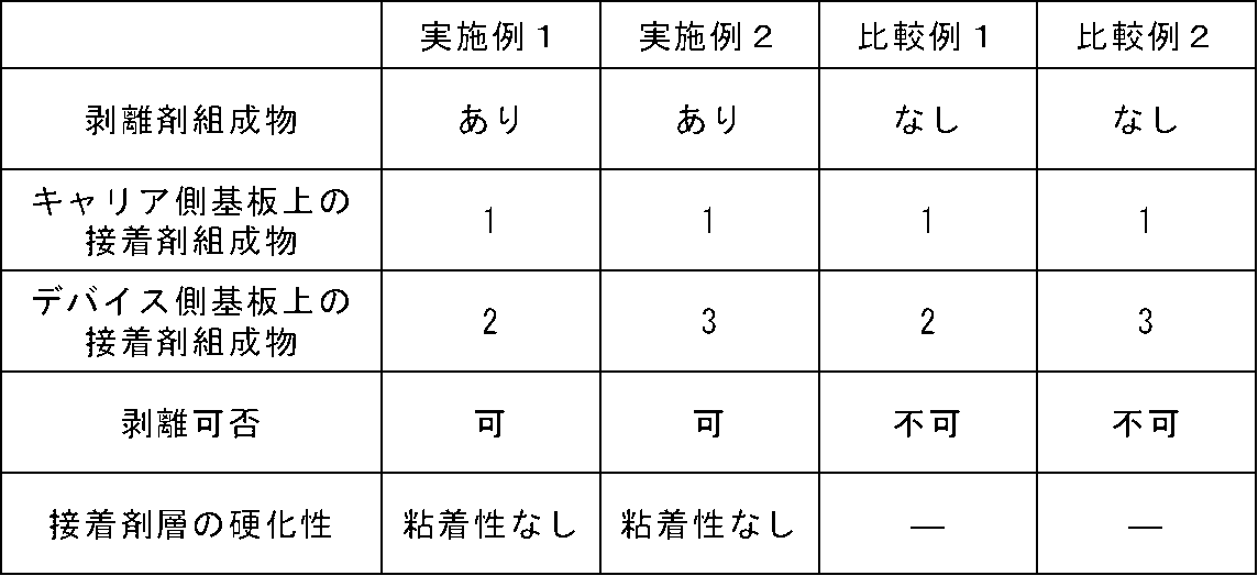
2 接着層
2A 第1の接着剤塗布層
2B 第2の接着剤塗布層
3 剥離層
3A 剥離剤塗布層
4 支持基板
Claims (8)
- 半導体基板と、光透過性の支持基板と、前記半導体基板と前記支持基板との間に設けられた、接着層と剥離層とを有し、前記支持基板側から照射された光を前記剥離層が吸収した後に前記半導体基板と前記支持基板とが剥がされることに用いられる積層体を製造する、積層体の製造方法であって、
前記支持基板の表面に形成された剥離剤塗布層の表面に第1の接着剤塗布層が形成される工程と、
前記半導体基板の表面に第2の接着剤塗布層が形成される工程と、
前記第1の接着剤塗布層と前記第2の接着剤塗布層との貼り合せ及び加熱が行われ、前記剥離剤塗布層から前記剥離層が形成され、前記第1の接着剤塗布層及び前記第2の接着剤塗布層から前記接着層が形成される工程と、
を含み、
前記第1の接着剤塗布層が、第1の接着剤組成物から形成され、
前記第2の接着剤塗布層が、第2の接着剤組成物から形成され、
前記第1の接着剤組成物及び前記第2の接着剤組成物が、以下の(1)又は(2)を満たす、
積層体の製造方法。
(1):前記第1の接着剤組成物が、第1の熱硬化成分と、触媒存在下で前記第1の熱硬化成分と反応する第2の熱硬化成分とを含有し、前記第2の接着剤組成物が、前記触媒を含有する。
(2):前記第2の接着剤組成物が、第1の熱硬化成分と、触媒存在下で前記第1の熱硬化成分と反応する第2の熱硬化成分とを含有し、前記第1の接着剤組成物が、前記触媒を含有する。 - 前記第1の熱硬化成分が、ケイ素原子に結合した炭素数2~40のアルケニル基を有し、
前記第2の熱硬化成分が、Si-H基を有し、
前記触媒が、白金族金属系触媒(A2)を含有する、
請求項1に記載の積層体の製造方法。 - 前記第1の熱硬化成分が、ケイ素原子に結合した炭素数2~40のアルケニル基を有するポリオルガノシロキサン(a1)を含有し、
前記第2の熱硬化成分が、Si-H基を有するポリオルガノシロキサン(a2)を含有する、
請求項2に記載の積層体の製造方法。 - 前記剥離剤塗布層が、剥離剤組成物から形成され、
前記剥離剤組成物が、有機樹脂を含有する、
請求項1に記載の積層体の製造方法。 - 前記有機樹脂が、ノボラック樹脂を含有する、
請求項4に記載の積層体の製造方法。 - 前記剥離剤組成物が、更に、架橋剤を含有する、
請求項4に記載の積層体の製造方法。 - 加工された半導体基板の製造方法であって、
請求項1~6のいずれかに記載の積層体の製造方法によって製造された前記積層体の前記半導体基板が加工される第1工程と、
前記第1工程によって加工された前記半導体基板と前記支持基板とが分離される第2工程と、
を含み、
前記第2工程が、前記剥離層に対して光が照射される工程を含む、
加工された半導体基板の製造方法。 - 請求項1~6のいずれかに記載の積層体の製造方法に用いられる接着剤組成物のキットであって、
前記第1の接着剤組成物及び前記第2の接着剤組成物を含有し、
前記第1の接着剤組成物及び前記第2の接着剤組成物が、以下の(1)又は(2)を満たす、
接着剤組成物のキット。
(1):前記第1の接着剤組成物が、第1の熱硬化成分と、触媒存在下で前記第1の熱硬化成分と反応する第2の熱硬化成分とを含有し、前記第2の接着剤組成物が、前記触媒を含有する。
(2):前記第2の接着剤組成物が、第1の熱硬化成分と、触媒存在下で前記第1の熱硬化成分と反応する第2の熱硬化成分とを含有し、前記第1の接着剤組成物が、前記触媒を含有する。
Priority Applications (5)
| Application Number | Priority Date | Filing Date | Title |
|---|---|---|---|
| CN202280051909.2A CN117716474A (zh) | 2021-07-26 | 2022-07-14 | 层叠体的制造方法和粘接剂组合物的套组 |
| US18/291,845 US20240363387A1 (en) | 2021-07-26 | 2022-07-14 | Method of manufacturing laminate and kit of adhesive compositions |
| KR1020247004184A KR20240040084A (ko) | 2021-07-26 | 2022-07-14 | 적층체의 제조 방법 및 접착제 조성물의 키트 |
| EP22849270.8A EP4369380A4 (en) | 2021-07-26 | 2022-07-14 | METHOD FOR MANUFACTURING LAMINATED BODY AND KIT FOR ADHESIVE COMPOSITION |
| JP2023538426A JPWO2023008207A1 (ja) | 2021-07-26 | 2022-07-14 |
Applications Claiming Priority (2)
| Application Number | Priority Date | Filing Date | Title |
|---|---|---|---|
| JP2021121582 | 2021-07-26 | ||
| JP2021-121582 | 2021-07-26 |
Publications (1)
| Publication Number | Publication Date |
|---|---|
| WO2023008207A1 true WO2023008207A1 (ja) | 2023-02-02 |
Family
ID=85087568
Family Applications (1)
| Application Number | Title | Priority Date | Filing Date |
|---|---|---|---|
| PCT/JP2022/027659 Ceased WO2023008207A1 (ja) | 2021-07-26 | 2022-07-14 | 積層体の製造方法、及び接着剤組成物のキット |
Country Status (7)
| Country | Link |
|---|---|
| US (1) | US20240363387A1 (ja) |
| EP (1) | EP4369380A4 (ja) |
| JP (1) | JPWO2023008207A1 (ja) |
| KR (1) | KR20240040084A (ja) |
| CN (1) | CN117716474A (ja) |
| TW (1) | TW202306789A (ja) |
| WO (1) | WO2023008207A1 (ja) |
Families Citing this family (2)
| Publication number | Priority date | Publication date | Assignee | Title |
|---|---|---|---|---|
| CN117157739A (zh) * | 2021-03-31 | 2023-12-01 | 日产化学株式会社 | 层叠体、剥离剂组合物以及经加工的半导体基板的制造方法 |
| CN120190758B (zh) * | 2025-04-23 | 2025-12-05 | 北京易感芯科技有限公司 | 磨抛样片载具及磨抛设备 |
Citations (11)
| Publication number | Priority date | Publication date | Assignee | Title |
|---|---|---|---|---|
| WO2005113648A1 (en) | 2004-05-14 | 2005-12-01 | Dow Corning Corporation | Method of making branched polysilanes |
| JP2007106894A (ja) | 2005-10-13 | 2007-04-26 | Nippon Soda Co Ltd | ポリシランの製造方法 |
| JP2007145879A (ja) | 2005-10-28 | 2007-06-14 | Nippon Soda Co Ltd | 分岐型ポリシラン化合物の製造方法 |
| JP2011208054A (ja) | 2010-03-30 | 2011-10-20 | Osaka Gas Chem Kk | ポリシランの製造方法 |
| WO2015190438A1 (ja) * | 2014-06-10 | 2015-12-17 | 日産化学工業株式会社 | 仮接着剤を用いた積層体 |
| JP2017013311A (ja) | 2015-06-30 | 2017-01-19 | 信越化学工業株式会社 | ウエハ加工用仮接着材、ウエハ加工体、及び薄型ウエハの製造方法 |
| WO2019088103A1 (ja) * | 2017-11-01 | 2019-05-09 | 日産化学株式会社 | ノボラック樹脂を剥離層として含む積層体 |
| WO2020105586A1 (ja) * | 2018-11-19 | 2020-05-28 | 日産化学株式会社 | 光照射剥離用接着剤組成物及び積層体並びに積層体の製造方法及び剥離方法 |
| WO2020111069A1 (ja) * | 2018-11-28 | 2020-06-04 | 日産化学株式会社 | 接着剤組成物、積層体及び積層体の製造方法並びに半導体形成基板を薄化する方法 |
| WO2020138240A1 (ja) * | 2018-12-27 | 2020-07-02 | 日産化学株式会社 | 光照射剥離用接着剤組成物及び積層体並びに積層体の製造方法及び剥離方法 |
| WO2021065547A1 (ja) * | 2019-09-30 | 2021-04-08 | 信越化学工業株式会社 | ウエハ加工体、ウエハ加工用仮接着材、及び薄型ウエハの製造方法 |
Family Cites Families (1)
| Publication number | Priority date | Publication date | Assignee | Title |
|---|---|---|---|---|
| JPH09324152A (ja) * | 1996-06-06 | 1997-12-16 | Toray Dow Corning Silicone Co Ltd | 同種もしくは異種の基材からなる接着構造体の製造方法 |
-
2022
- 2022-07-14 WO PCT/JP2022/027659 patent/WO2023008207A1/ja not_active Ceased
- 2022-07-14 US US18/291,845 patent/US20240363387A1/en active Pending
- 2022-07-14 CN CN202280051909.2A patent/CN117716474A/zh active Pending
- 2022-07-14 KR KR1020247004184A patent/KR20240040084A/ko active Pending
- 2022-07-14 JP JP2023538426A patent/JPWO2023008207A1/ja active Pending
- 2022-07-14 EP EP22849270.8A patent/EP4369380A4/en active Pending
- 2022-07-15 TW TW111126738A patent/TW202306789A/zh unknown
Patent Citations (11)
| Publication number | Priority date | Publication date | Assignee | Title |
|---|---|---|---|---|
| WO2005113648A1 (en) | 2004-05-14 | 2005-12-01 | Dow Corning Corporation | Method of making branched polysilanes |
| JP2007106894A (ja) | 2005-10-13 | 2007-04-26 | Nippon Soda Co Ltd | ポリシランの製造方法 |
| JP2007145879A (ja) | 2005-10-28 | 2007-06-14 | Nippon Soda Co Ltd | 分岐型ポリシラン化合物の製造方法 |
| JP2011208054A (ja) | 2010-03-30 | 2011-10-20 | Osaka Gas Chem Kk | ポリシランの製造方法 |
| WO2015190438A1 (ja) * | 2014-06-10 | 2015-12-17 | 日産化学工業株式会社 | 仮接着剤を用いた積層体 |
| JP2017013311A (ja) | 2015-06-30 | 2017-01-19 | 信越化学工業株式会社 | ウエハ加工用仮接着材、ウエハ加工体、及び薄型ウエハの製造方法 |
| WO2019088103A1 (ja) * | 2017-11-01 | 2019-05-09 | 日産化学株式会社 | ノボラック樹脂を剥離層として含む積層体 |
| WO2020105586A1 (ja) * | 2018-11-19 | 2020-05-28 | 日産化学株式会社 | 光照射剥離用接着剤組成物及び積層体並びに積層体の製造方法及び剥離方法 |
| WO2020111069A1 (ja) * | 2018-11-28 | 2020-06-04 | 日産化学株式会社 | 接着剤組成物、積層体及び積層体の製造方法並びに半導体形成基板を薄化する方法 |
| WO2020138240A1 (ja) * | 2018-12-27 | 2020-07-02 | 日産化学株式会社 | 光照射剥離用接着剤組成物及び積層体並びに積層体の製造方法及び剥離方法 |
| WO2021065547A1 (ja) * | 2019-09-30 | 2021-04-08 | 信越化学工業株式会社 | ウエハ加工体、ウエハ加工用仮接着材、及び薄型ウエハの製造方法 |
Non-Patent Citations (1)
| Title |
|---|
| See also references of EP4369380A4 |
Also Published As
| Publication number | Publication date |
|---|---|
| KR20240040084A (ko) | 2024-03-27 |
| EP4369380A1 (en) | 2024-05-15 |
| US20240363387A1 (en) | 2024-10-31 |
| TW202306789A (zh) | 2023-02-16 |
| JPWO2023008207A1 (ja) | 2023-02-02 |
| EP4369380A4 (en) | 2025-07-09 |
| CN117716474A (zh) | 2024-03-15 |
Similar Documents
| Publication | Publication Date | Title |
|---|---|---|
| JP7698242B2 (ja) | 積層体、剥離剤組成物及び加工された半導体基板の製造方法 | |
| EP4398285A1 (en) | Adhesive composition, multilayer body, and method for producing processed semiconductor substrate | |
| WO2023008207A1 (ja) | 積層体の製造方法、及び接着剤組成物のキット | |
| EP4583149A1 (en) | Release agent composition for photoirradiation release, laminate, and method for producing processed semiconductor substrate | |
| EP4678708A1 (en) | Adhesive composition, laminate, and method for producing processed semiconductor substrate | |
| EP4653507A1 (en) | Adhesive composition, laminate, and method for producing processed semiconductor substrate | |
| WO2025057891A1 (ja) | 接着剤組成物、積層体、及び加工された半導体基板の製造方法 | |
| WO2026028984A1 (ja) | 接着剤組成物、積層体、及び加工された半導体基板の製造方法 | |
| WO2025198034A1 (ja) | 加工された半導体基板の製造方法 | |
| WO2025094864A1 (ja) | 接着剤組成物、積層体、及び加工された半導体基板の製造方法 | |
| TW202611252A (zh) | 接著劑組成物、積層體、及加工後之半導體基板之製造方法 | |
| WO2025094880A1 (ja) | 接着剤組成物、積層体、及び加工された半導体基板の製造方法 | |
| WO2025094889A1 (ja) | 接着剤組成物、積層体、及び加工された半導体基板の製造方法 | |
| JP2024135070A (ja) | 剥離剤組成物、積層体、及び加工された半導体基板又は電子デバイス層の製造方法 | |
| WO2025094887A1 (ja) | 接着剤組成物、積層体、及び加工された半導体基板の製造方法 | |
| KR20250135816A (ko) | 접착제 조성물, 적층체, 및 가공된 반도체 기판의 제조 방법 | |
| TW202609864A (zh) | 加工後之半導體基板之製造方法 | |
| TW202440845A (zh) | 光照射剝離用之剝離劑組成物、及光照射剝離用之接著劑組成物 | |
| TW202611259A (zh) | 接著劑組成物 |
Legal Events
| Date | Code | Title | Description |
|---|---|---|---|
| 121 | Ep: the epo has been informed by wipo that ep was designated in this application |
Ref document number: 22849270 Country of ref document: EP Kind code of ref document: A1 |
|
| WWE | Wipo information: entry into national phase |
Ref document number: 2023538426 Country of ref document: JP |
|
| WWE | Wipo information: entry into national phase |
Ref document number: 202280051909.2 Country of ref document: CN |
|
| ENP | Entry into the national phase |
Ref document number: 20247004184 Country of ref document: KR Kind code of ref document: A |
|
| WWE | Wipo information: entry into national phase |
Ref document number: 1020247004184 Country of ref document: KR Ref document number: 2022849270 Country of ref document: EP |
|
| ENP | Entry into the national phase |
Ref document number: 2022849270 Country of ref document: EP Effective date: 20240205 |
|
| NENP | Non-entry into the national phase |
Ref country code: DE |
|
| WWE | Wipo information: entry into national phase |
Ref document number: 11202400485V Country of ref document: SG |