WO2023013280A1 - タイヤ - Google Patents
タイヤ Download PDFInfo
- Publication number
- WO2023013280A1 WO2023013280A1 PCT/JP2022/025149 JP2022025149W WO2023013280A1 WO 2023013280 A1 WO2023013280 A1 WO 2023013280A1 JP 2022025149 W JP2022025149 W JP 2022025149W WO 2023013280 A1 WO2023013280 A1 WO 2023013280A1
- Authority
- WO
- WIPO (PCT)
- Prior art keywords
- groove
- tire
- main
- tread
- width
- Prior art date
- Legal status (The legal status is an assumption and is not a legal conclusion. Google has not performed a legal analysis and makes no representation as to the accuracy of the status listed.)
- Ceased
Links
Images


Classifications
-
- B—PERFORMING OPERATIONS; TRANSPORTING
- B60—VEHICLES IN GENERAL
- B60C—VEHICLE TYRES; TYRE INFLATION; TYRE CHANGING; CONNECTING VALVES TO INFLATABLE ELASTIC BODIES IN GENERAL; DEVICES OR ARRANGEMENTS RELATED TO TYRES
- B60C11/00—Tyre tread bands; Tread patterns; Anti-skid inserts
- B60C11/03—Tread patterns
- B60C11/13—Tread patterns characterised by the groove cross-section, e.g. for buttressing or preventing stone-trapping
-
- B—PERFORMING OPERATIONS; TRANSPORTING
- B60—VEHICLES IN GENERAL
- B60C—VEHICLE TYRES; TYRE INFLATION; TYRE CHANGING; CONNECTING VALVES TO INFLATABLE ELASTIC BODIES IN GENERAL; DEVICES OR ARRANGEMENTS RELATED TO TYRES
- B60C11/00—Tyre tread bands; Tread patterns; Anti-skid inserts
- B60C11/03—Tread patterns
- B60C11/0306—Patterns comprising block rows or discontinuous ribs
- B60C11/0309—Patterns comprising block rows or discontinuous ribs further characterised by the groove cross-section
-
- B—PERFORMING OPERATIONS; TRANSPORTING
- B60—VEHICLES IN GENERAL
- B60C—VEHICLE TYRES; TYRE INFLATION; TYRE CHANGING; CONNECTING VALVES TO INFLATABLE ELASTIC BODIES IN GENERAL; DEVICES OR ARRANGEMENTS RELATED TO TYRES
- B60C11/00—Tyre tread bands; Tread patterns; Anti-skid inserts
- B60C11/03—Tread patterns
- B60C11/0311—Patterns comprising tread lugs arranged parallel or oblique to the axis of rotation
- B60C11/0316—Patterns comprising tread lugs arranged parallel or oblique to the axis of rotation further characterised by the groove cross-section
-
- B—PERFORMING OPERATIONS; TRANSPORTING
- B60—VEHICLES IN GENERAL
- B60C—VEHICLE TYRES; TYRE INFLATION; TYRE CHANGING; CONNECTING VALVES TO INFLATABLE ELASTIC BODIES IN GENERAL; DEVICES OR ARRANGEMENTS RELATED TO TYRES
- B60C11/00—Tyre tread bands; Tread patterns; Anti-skid inserts
- B60C11/03—Tread patterns
- B60C11/04—Tread patterns in which the raised area of the pattern consists only of continuous circumferential ribs, e.g. zig-zag
-
- B—PERFORMING OPERATIONS; TRANSPORTING
- B60—VEHICLES IN GENERAL
- B60C—VEHICLE TYRES; TYRE INFLATION; TYRE CHANGING; CONNECTING VALVES TO INFLATABLE ELASTIC BODIES IN GENERAL; DEVICES OR ARRANGEMENTS RELATED TO TYRES
- B60C11/00—Tyre tread bands; Tread patterns; Anti-skid inserts
- B60C11/03—Tread patterns
- B60C11/13—Tread patterns characterised by the groove cross-section, e.g. for buttressing or preventing stone-trapping
- B60C11/1307—Tread patterns characterised by the groove cross-section, e.g. for buttressing or preventing stone-trapping with special features of the groove walls
-
- B—PERFORMING OPERATIONS; TRANSPORTING
- B60—VEHICLES IN GENERAL
- B60C—VEHICLE TYRES; TYRE INFLATION; TYRE CHANGING; CONNECTING VALVES TO INFLATABLE ELASTIC BODIES IN GENERAL; DEVICES OR ARRANGEMENTS RELATED TO TYRES
- B60C11/00—Tyre tread bands; Tread patterns; Anti-skid inserts
- B60C11/03—Tread patterns
- B60C2011/0337—Tread patterns characterised by particular design features of the pattern
- B60C2011/0339—Grooves
- B60C2011/0341—Circumferential grooves
- B60C2011/0344—Circumferential grooves provided at the equatorial plane
-
- B—PERFORMING OPERATIONS; TRANSPORTING
- B60—VEHICLES IN GENERAL
- B60C—VEHICLE TYRES; TYRE INFLATION; TYRE CHANGING; CONNECTING VALVES TO INFLATABLE ELASTIC BODIES IN GENERAL; DEVICES OR ARRANGEMENTS RELATED TO TYRES
- B60C11/00—Tyre tread bands; Tread patterns; Anti-skid inserts
- B60C11/03—Tread patterns
- B60C2011/0337—Tread patterns characterised by particular design features of the pattern
- B60C2011/0339—Grooves
- B60C2011/0341—Circumferential grooves
- B60C2011/0353—Circumferential grooves characterised by width
-
- B—PERFORMING OPERATIONS; TRANSPORTING
- B60—VEHICLES IN GENERAL
- B60C—VEHICLE TYRES; TYRE INFLATION; TYRE CHANGING; CONNECTING VALVES TO INFLATABLE ELASTIC BODIES IN GENERAL; DEVICES OR ARRANGEMENTS RELATED TO TYRES
- B60C11/00—Tyre tread bands; Tread patterns; Anti-skid inserts
- B60C11/03—Tread patterns
- B60C2011/0337—Tread patterns characterised by particular design features of the pattern
- B60C2011/0339—Grooves
- B60C2011/0358—Lateral grooves, i.e. having an angle of 45 to 90 degees to the equatorial plane
- B60C2011/0365—Lateral grooves, i.e. having an angle of 45 to 90 degees to the equatorial plane characterised by width
-
- Y—GENERAL TAGGING OF NEW TECHNOLOGICAL DEVELOPMENTS; GENERAL TAGGING OF CROSS-SECTIONAL TECHNOLOGIES SPANNING OVER SEVERAL SECTIONS OF THE IPC; TECHNICAL SUBJECTS COVERED BY FORMER USPC CROSS-REFERENCE ART COLLECTIONS [XRACs] AND DIGESTS
- Y02—TECHNOLOGIES OR APPLICATIONS FOR MITIGATION OR ADAPTATION AGAINST CLIMATE CHANGE
- Y02T—CLIMATE CHANGE MITIGATION TECHNOLOGIES RELATED TO TRANSPORTATION
- Y02T10/00—Road transport of goods or passengers
- Y02T10/80—Technologies aiming to reduce greenhouse gasses emissions common to all road transportation technologies
- Y02T10/86—Optimisation of rolling resistance, e.g. weight reduction
Definitions
- the present invention relates to tires.
- noise caused by air column resonance is the main cause of outside noise generated from tires.
- the air column resonance noise is noise generated by resonance of the air in the pipe surrounded by the circumferential grooves extending continuously in the circumferential direction of the tread surface and the road surface.
- a land portion divided by a plurality of circumferential main grooves is substantially sealed inside the land portion and both ends in the length direction are
- a Helmholtz-type resonator is provided, which is composed of a cavity that is interrupted inside a land portion, communication holes that communicate the cavity with the circumferential main groove, and sipes (Patent Document 1).
- an object of the present invention is to provide a tire that can reduce columnar resonance noise during vehicle travel.
- the gist of the present invention is as follows.
- a tire having a plurality of circumferential main grooves on the tread surface that extend in the tire circumferential direction and have groove widths that prevent both side walls from coming into contact with each other when the tire touches the ground Of the plurality of circumferential main grooves, when a pair of circumferential main grooves arranged closest to both tread edges in the tire width direction are referred to as shoulder main grooves, At least one of the shoulder main grooves is a normal main groove configured such that the maximum groove width position in the groove depth direction is only the tread tread position, At least one circumferential main groove other than the at least one shoulder main groove is configured such that at least one maximum groove width position in the groove depth direction is positioned closer to the groove bottom than the tread tread position.
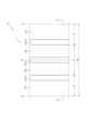
- FIG. 1 is a partial development view schematically showing a tread surface of a tire according to a first embodiment of the present invention
- FIG. FIG. 2 is a cross-sectional view in the tire width direction showing a portion of the tire in FIG. 1 in a cross section taken along line AA in FIG. 1
- FIG. 3 is a tire width direction partial cross-sectional view schematically showing an enlarged part of the tire shown in FIG. 2
- FIG. 3 is a tire width direction partial cross-sectional view schematically showing an enlarged part of the tire shown in FIG. 2
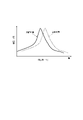
- FIG. 4 is a diagram for explaining the frequency of air column resonance
- FIG. 5 is a diagram for explaining another example of the widened main groove
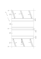
- FIG. 6 is a partial development view schematically showing a tread surface of a tire according to a second embodiment of the present invention
- FIG. 4 is a diagram for explaining the frequency of air column resonance
- FIG. 7 is a partially expanded view schematically showing an enlarged part of the tread surface shown in FIG. 6
- FIG. 10 is a diagram for explaining another example of width direction grooves
- the tire according to the invention can be used for any type of tire, preferably for passenger cars.
- any type of tire preferably for passenger cars.
- embodiments of the tire according to the present invention will be described by way of example with reference to the drawings. The same reference numerals are given to common components in each figure.
- the tire of each embodiment described herein may have any internal configuration.
- the tire of each embodiment described in this specification includes, for example, a pair of bead cores (not shown) provided in a pair of bead portions, and a pair of bead fillers (not shown) positioned outside the bead cores in the tire radial direction. , a carcass 70 (FIG. 2), a belt 60 (FIG. 2), and a tread rubber 80 (FIG. 2).
- the carcass 70 extends like a toroid between a pair of bead cores.
- the carcass 70 includes at least one carcass ply (one layer in the illustrated example).
- the carcass plies of the carcass 70 can have a structure in which cords made of steel or organic fibers are covered with rubber, for example.
- the carcass 70 includes, for example, a body portion extending in a toroidal shape between a pair of bead cores, and on each of both sides with respect to the tire equatorial plane CL, from the innermost end of the body portion in the tire radial direction to the outer side in the tire width direction around the bead cores. and a pair of folds folded toward.
- the belt 60 is arranged outside the crown region of the carcass 70 in the tire radial direction in the tread portion 90 ( FIG. 2 ).
- the belt 60 is composed of at least one belt layer (two layers in the example shown).
- the belt layer can have, for example, a structure in which a cord made of steel or organic fiber is covered with rubber.
- the tread rubber 80 is arranged outside the belt 60 in the tire radial direction.
- the term “tread surface (1)” refers to a tire that is mounted on a rim and has a predetermined internal pressure, and when the tire is rolled with the maximum load applied, it comes into contact with the road surface. , means the outer peripheral surface of the tire over its entire circumference.
- “tread edge (TE)” means an edge in the tire width direction of the tread surface (1).
- the term “contact length” means the length along the circumferential direction of the contact surface between the tire and the road surface, and the term “contact surface” refers to the tire that is attached to the rim and filled with a predetermined internal pressure. It means the outer peripheral surface of the tire that contacts the road surface when the tire is grounded with the maximum load applied.
- rim is an industrial standard effective in the region where tires are produced and used.
- Technical Organization Standards Manual, TRA (The Tire and Rim Association, Inc.) YEAR BOOK in the United States, or standard rims in application sizes (Measuring Rim in ETRTO's STANDARDS MANUAL) , Design Rim in TRA's YEAR BOOK) (i.e., the above "rim” includes sizes that may be included in the above industrial standards in the future in addition to current sizes.
- predetermined internal pressure refers to the air pressure (maximum air pressure) that corresponds to the maximum load capacity of a single wheel in the applicable size and ply rating described in the above JATMA YEAR BOOK, etc., and is described in the above industrial standards. For sizes without , it means the air pressure (maximum air pressure) corresponding to the maximum load capacity specified for each vehicle on which the tire is installed.
- Maximum load means the load corresponding to the maximum load capacity.
- the air referred to here can be replaced with an inert gas such as nitrogen gas.
- the dimensions of each element such as grooves and land portions, contact width (TW), etc. shall be measured under the “reference condition” described later.
- the term “reference state” refers to a state in which the tire is mounted on a rim, filled with the above predetermined internal pressure, and placed in an unloaded state.
- the "groove width of the circumferential main groove” refers to the length in the direction orthogonal to the extending direction of the circumferential main groove, measured in the above-described reference state.
- the “groove width of the widthwise groove” refers to the length in the direction perpendicular to the extending direction of the widthwise groove measured in the reference state.
- FIG. 1 is a partial development view schematically showing a tread surface 1 of a tire 10 according to a first embodiment of the invention.
- FIG. 2 is a cross-sectional view in the tire width direction showing a portion of the tire 10 of FIG. 1 in cross section along line AA of FIG. 3A is a tire width direction partial sectional view schematically showing an enlarged part of the tire shown in FIG. 2, and FIG. 3B schematically showing an enlarged part of the tire shown in FIG. , and a partial sectional view in the tire width direction.
- the tire 10 of the first embodiment has a plurality of circumferential main grooves 2 on the tread surface 1 .
- Each circumferential main groove 2 extends in the tire circumferential direction.
- Each circumferential main groove 2 may extend linearly along the circumferential direction, as shown in FIG.
- a pair of circumferential main grooves arranged closest to the tread edges TE on both sides in the tire width direction are referred to as a pair of shoulder main grooves 21a and 21b.
- the circumferential main groove located inside the pair of shoulder main grooves 21 a and 21 b in the tire width direction is referred to as a center main groove 22 .
- the number of circumferential main grooves 2 is preferably three or more (three in the present embodiment) as in the present embodiment from the viewpoint of drainage, but may be two.
- Each circumferential main groove 2 has a groove width such that both sidewalls do not contact each other when the tire touches the ground. That is, when the tire is mounted on the rim, filled with a predetermined internal pressure, and the maximum load is applied, the pair of groove walls facing each other do not come into contact with each other at a position directly under the load.
- Each land portions 31a, 31b, 32a and 32b are defined on the tread surface 1 of the tire 10 of the first embodiment by the shoulder main grooves 21a and 21b, the center main groove 22, and the tread edge TE.
- Shoulder land portions 31a and 31b are defined on the outside in the tire width direction by the tread edge TE and the shoulder main grooves 21a and 21b.
- Center land portions 32a and 32b are defined on the inner side in the tire width direction.
- At least one of the shoulder main grooves in the first embodiment, both of the pair of shoulder main grooves 21a and 21b, has the maximum groove width position only at the tread surface position in the groove depth direction. Constructed to be, usually the main groove. That is, in the standard state, the shoulder main grooves 21a and 21b have the maximum width w1 at the position of the tread surface 1, and the inner side of the tread surface 1 in the tire radial direction, that is, the groove bottom side, can be also has a groove width smaller than the groove width w1.
- the groove width gradually decreases inward in the tire radial direction from the groove width w1 side of the tread surface 1, and the groove width w2 at the groove bottom is the minimum groove width.
- the "normal main groove” may have the maximum groove width position only at the tread surface position, and the minimum groove width position may be at a position other than the groove bottom.
- “gradually decreasing” means that the groove width is constantly decreasing.
- At least one circumferential main groove other than at least one of the shoulder main grooves, in this embodiment the center main groove 22, has at least one maximum groove width in the groove depth direction.
- the widened main groove is configured so that the position is closer to the groove bottom than the tread tread position.
- the center main groove 22 has a maximum width w4 at the groove bottom in the reference state, and the groove width w4 is the maximum width at any position on the outer side of the groove bottom in the tire radial direction, that is, on the tread surface 1 side. It has a groove width smaller than the width w4.
- the groove width gradually decreases outward in the tire radial direction from the groove width w4 side at the groove bottom, and the groove width w3 at the tread surface 1 is the minimum groove width.
- the "widened main groove” at least one of the maximum groove width positions in the groove depth direction should be closer to the groove bottom than the tread surface position, and the "widened main groove” has the maximum groove in the groove depth direction.
- a structure with a plurality of width positions and a structure in which the groove width is constant in the groove depth direction are also included.
- the width of the "widened main groove” is not constant in the groove depth direction. It is preferable that the maximum groove width position is closer to the groove bottom than the tread surface.
- FIG. 4 is a diagram for explaining the frequency of air column resonance in the circumferential main groove.
- FIG. 4 shows the relationship between the sound pressure and the frequency of the air column resonance in the normal main groove and the air column resonance in the widened main groove. Since the maximum groove width of the main groove is usually located only at the tread surface, the opening of the groove that comes into contact with the road surface and the air is, so to speak, open. On the other hand, the widened main groove has the maximum groove width position closer to the groove bottom than the tread surface position, so the opening of the groove that contacts the road surface and air is closed compared to the normal main groove. ing.
- the widened main groove behaves as a relatively "longer" tube than the normal main groove of the same cross-sectional area due to the open end correction.
- the frequency of the air column resonance noise generated in the circumferential main groove during vehicle running becomes relatively low. Therefore, in the widened main groove, the peak of the sound pressure level can be shifted to the lower frequency side than in the normal main groove. In this way, by shifting the frequency at the peak of the air column resonance sound generated in the circumferential main groove during vehicle running between the normal main groove and the widened main groove, the peak value of the sum of these sound pressures can be reduced. Since it can be lowered, it is possible to reduce the air column resonance sound and alleviate the noise of the entire tire (to make it less likely to be offensive).
- the maximum groove width position of the center main groove 22 is located at the bottom of the groove rather than the tread surface position, when the wear of the tire progresses, the groove width becomes large. Compared to the case where the center main groove 22 is exposed to the tread tread surface 1 and the maximum groove width position of the center main groove 22 is located at the tread tread surface position, drainage performance can be improved when wear progresses, and drainage performance does not decrease even when wear progresses. can be suppressed. Since the center main groove 22 is located inside the shoulder main grooves 21a and 21b in the tire width direction, the contact pressure in the tire width direction when the tire travels straight tends to be relatively higher than on the shoulder main groove side. In particular, it is effective in securing sufficient drainage during straight running when wear progresses.
- the number of normal main grooves and widened main grooves is not particularly limited as long as they are one or more, respectively. and at least one center main groove 22, the pair of shoulder main grooves 21a and 21b being normal main grooves and the center main groove 22 being preferably an enlarged main groove.
- the ground contact length of a tire is longer on the tire equatorial plane CL side than on the tread end TE side.
- the circumferential main groove on the surface CL side is longer.
- the frequency of the sound pressure peak of the air column resonance sound is higher in the circumferential main groove with the longer contact length than in the circumferential main groove with the shorter contact length. Therefore, in general, the frequency of the sound pressure peak of air column resonance is lower in the circumferential main groove on the tire equatorial plane CL side than in the circumferential main groove on the tread edge TE side. Therefore, the circumferential main groove on the tread edge TE side is the normal main groove, and the circumferential main groove on the tire equatorial plane CL side is the widened main groove in which the sound pressure peak frequency is lower than that of the normal main groove as described above.
- the number of center main grooves 22, which are widened main grooves, is one, and the number of shoulder main grooves 21a and 21b, which are normal main grooves, is two.
- the ratio of the number of widened main grooves to the number of widened main grooves is 1/2, but the ratio of the number of widened main grooves to the number of normal main grooves is not particularly limited.
- the ratio of the number of widened main grooves to the number of normal main grooves is preferably 1/1 to 3/2. According to such a configuration, the frequencies of the air column resonance noise are dispersed in a well-balanced manner when the vehicle is running, the air column resonance noise is more effectively reduced, and the noise of the entire tire is reduced. can do.
- the center main groove 22, which is the widened main groove preferably has a portion where the groove width gradually increases from the tread surface 1 side toward the groove bottom side. According to such a configuration, it is possible to suppress the deterioration of the drainage performance in the long term when the wear progresses. More preferably, the groove width gradually increases from the tread surface 1 to the groove bottom. According to such a configuration, it is possible to more effectively suppress the deterioration of the drainage performance in the long term when the wear progresses.
- each of the circumferential main grooves 2 may have a groove width such that both sidewalls do not contact each other when the tire touches the ground.
- the groove width w2 and groove width w3) are preferably 1.5 mm or more. According to such a configuration, it is possible to reliably reduce air column resonance noise when the vehicle is running, and to ensure sufficient drainage performance both when the tire is brand new and when wear has progressed.
- each circumferential main groove 2 (groove depths d1 and d2 in the examples of FIGS. 3A and 3B) is preferably 3.0 mm or more. This ensures adequate drainage. From the viewpoint of the rigidity of the tire 10, the groove depth of each circumferential main groove 2 (groove depths d1 and d2 in the examples of FIGS. 3A and 3B) is preferably 20 mm or less. More preferably, the groove depth of each circumferential main groove 2 is 3.0 mm or more from the viewpoint of ensuring sufficient drainage performance, and is 15 mm or less from the viewpoint of the rigidity of the tire 10 .
- the inclination angles ⁇ 1 and ⁇ 2 of the side walls 211 and 222 forming the shoulder main grooves 21a and 21b, which are normal main grooves, are preferably 91° or more from the viewpoint of ensuring rigidity.
- the inclination angles ⁇ 1 and ⁇ 2 are preferably 150° or less from the viewpoint of ensuring sufficient drainage. More preferably, the angles of inclination ⁇ 1 and ⁇ 2 are 100° or more from the viewpoint of ensuring rigidity, and 130° or less from the viewpoint of ensuring sufficient drainage.
- the "inclination angle of the side walls 211 and 222 forming the shoulder main grooves 21a and 21b, which are normal main grooves” means, in the cross-sectional view in the tire width direction, at the opening ends of the shoulder main grooves 21a and 2b, respectively. It means the angle formed by the tread surface 1 and the side wall 211 and the tread surface 1 and the side wall 222 respectively.
- the inclination angles ⁇ 3 and ⁇ 4 of the side walls 221 and 222 forming the center main groove 22, which is the widened main groove, are set to 30 to prevent the opening edge from being lifted off on the tread surface 1 during ground contact. ° or more.
- the inclination angles ⁇ 3 and ⁇ 4 are preferably 89° or less in order to suppress the deterioration of the drainage property during the progress of wear over a long period of time. More preferably, the angles of inclination ⁇ 3 and ⁇ 4 are 50° or more from the viewpoint of effectively preventing cracking of the open end of the tread surface 1 at the time of ground contact, and more effectively reduce the deterioration of drainage performance at the time of progress of wear.
- the “inclination angles of the side walls 221 and 222 forming the center main groove 22, which is the widening main groove,” refer to the tread surface 1 and the side wall 221, the tread surface 1 and the side wall 222 at the opening end of the center main groove 22. means the angle formed by
- the side wall 221 and the groove bottom 223, and the side wall 222 and the groove bottom 223, which constitute the center main groove 22, which is the widened main groove, are the extension of the groove.
- the boundary between the side wall 221 and the groove bottom 223 and the boundary between the side wall 222 and the groove bottom 223 have curvature radii R1 and R2.
- Arc-shaped sidewalls and groove bottoms may also be used. With such a configuration, the durability of the center main groove 22, which is the widened main groove, can be enhanced.
- the values of the curvature radii R1 and R2 are not particularly limited, but the curvature radii R1 and R2 are preferably 0.5 mm or more. Such a configuration effectively prevents cracks at the boundary between the side wall 221 or the side wall 222 and the groove bottom 223 , thereby further enhancing the durability of the center main groove 22 .
- the curvature radii R1 and R2 be 5.0 mm or less. More preferably, the radii of curvature R1 and R2 are 1 mm or more from the viewpoint of increasing the durability of the center main groove 22, and 3.0 mm or less from the viewpoint of drainage.
- the center main groove 22 is entirely located in the center region C, and the shoulder main grooves 21a and 21b are entirely located in the shoulder region S, respectively.
- the center region C refers to a region of the tread surface 1 centered on the tire equatorial plane CL and whose width in the tire width direction is 50% of the ground contact width TW.
- the shoulder regions S refer to a pair of regions located outside the center region C in the tire width direction in the tread surface 1 . According to such a configuration, it is possible to more effectively reduce air column resonance and ensure sufficient drainage.
- the contact length of the tire 10 is longer on the tire equatorial plane CL side than on the tread edge TE side. Further, in the tire 10 of the first embodiment, it is preferable that the contact length of the circumferential main groove 2 is longer in the center main groove 22 than in the shoulder main grooves 21a and 21b. As described above, with such a configuration, it is possible to reliably shift the peak frequency of air column resonance noise generated in the circumferential main grooves between the normal main grooves and the widened main grooves while the vehicle is running. , air column resonance can be reduced, and the noise of the entire tire can be alleviated (made less harsh).
- the tire 11 of the second embodiment has a configuration similar to that of the tire 10 of the first embodiment except that it has width direction grooves normally communicating with the main grooves. , are denoted by the same reference numerals, and the description thereof is omitted.
- FIG. 6 is a partial development view schematically showing the tread surface of the tire 11 according to the second embodiment of the present invention.
- the tire 11 of the second embodiment communicates with shoulder main grooves 21a and 21b, which are normal main grooves, in the tire width direction (in this embodiment, at a predetermined angle exceeding 0° with respect to the tire width direction). It has widthwise grooves 4 which extend and open at the tread edge TE.
- the widthwise grooves 4 are arranged in the shoulder land portions 31a and 31b, respectively communicate with the shoulder main grooves 21a and 21b, extend in the tire width direction, and open at the tread edge TE. are doing.
- the width direction grooves 4 may be either line-symmetrical or point-symmetrical with respect to the tire equatorial plane CL, and may not be line-symmetrical or point-symmetrical with respect to the tire equatorial plane CL.
- the width direction grooves 4 arranged in the shoulder land portion 31a and the width direction grooves 4 arranged in the shoulder land portion 31b are symmetrical with respect to the tire equatorial plane CL. It is arranged in the wrong direction.
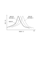
- FIG. 7 is a diagram for explaining the frequency of air column resonance in the circumferential main groove.
- FIG. 7 shows the relationship between sound pressure and frequency of air column resonance in the normal main groove (with widthwise grooves), the normal main groove (without widthwise grooves), and the widened main groove.
- normal main groove (with widthwise groove) refers to a normal main groove having a widthwise groove that communicates with the normal main groove, extends in the tire width direction, and opens at the tread edge TE.
- main groove (without widthwise grooves) refers to a normal main groove that does not have widthwise grooves.
- the normal main groove having the width direction groove can shift the peak of the sound pressure level to the high frequency side compared to the normal main groove having no width direction groove.
- the widened main groove similarly to the widened main groove of the tire 10 of the first embodiment, also in the tire 11 of the second embodiment, the widened main groove has a higher sound pressure level peak than the normal main groove having no width direction groove. can be shifted to the low frequency side.
- the normal main groove having the width direction groove and the widened main groove can shift the peak frequency of the air column resonance sound generated in the circumferential direction main groove when the vehicle is running, and furthermore, these sounds can be displaced. Since the peak value of the sum of pressures can be made lower, air column resonance can be reduced more efficiently.
- FIG. 8 is a partially expanded view schematically showing an enlarged part of the tread surface of FIG. 6 .
- FIG. 8 is drawn so that the scale is slightly different from that of FIG.
- the width direction grooves 4 are arranged in the shoulder land portions 31a and 31b, respectively, but as described above, in the example of FIG. Since they have the same configuration except for the arrangement, the width direction groove 4 arranged in the shoulder land portion 31a will be described below as a typical example.
- the width direction grooves 4 may have a shape in which the groove width on the tread surface 1 is constant, or may have a shape in which the groove width changes midway in the tire width direction.
- the width of the width direction groove 4 on the tread surface 1 is preferably larger on the side that opens toward the tread end TE than on the side that communicates with the shoulder main groove 21a, which is a normal main groove.
- the widthwise groove 4 is connected to a first widthwise groove portion 4a that communicates with the shoulder main groove 21a, adjacent to the tread edge TE side of the first widthwise groove portion 4a. and a second widthwise groove portion 4b, which opens into.
- a groove width w6 at the tread surface 1 of the second width direction groove portion 4b is larger than a groove width w5 at the tread surface 1 of the first width direction groove portion 4a.
- the groove width w5 of the first width direction groove portion 4a communicating with the shoulder main groove 21a is narrower than the groove width w6 of the second width direction groove portion 4b by 1 mm or more. preferably. With such a configuration, the effect of reducing air column resonance can be further enhanced.
- the groove width w5 of the first width direction groove portion 4a on the tread surface 1 is preferably 0.3 mm or more. With such a configuration, a sufficient amount of air can flow from the shoulder main groove 21a into the first width direction groove portion 4a, and the air column resonance noise reduction function can be exhibited more effectively. More preferably, it is 0.4 mm or more.
- the groove width w6 on the tread surface 1 of the second width direction groove portion 4b that opens at the tread end TE may be a groove width that does not allow both side walls to contact each other when the tire touches the ground. It is more preferable to have a groove width of 0.5 mm or more. According to such a configuration, the effect of reducing air column resonance noise can be effectively realized, and sufficient drainage can be ensured.
- the groove depth of the first width direction groove portion 4a of the width direction groove 4 is preferably approximately the same as the groove depth of the second width direction groove portion 4b. This is because, with such a configuration, it is possible to maintain drainage performance and reduce air columnar resonance noise even in the tire after wear.
- the groove depth of the second widthwise groove portion 4b is preferably approximately the same as that of the shoulder main groove 21a. More specifically, it is preferable to set the groove depth of the second width direction groove portion 4b to 3.0 mm or more. As a result, sufficient drainage can be ensured.
- the groove depth of the second width direction groove portion 4b is preferably 20 mm or less. More preferably, the groove depth of the second width direction groove portion 4b is 5.0 mm or more from the viewpoint of ensuring sufficient drainage performance, and is 15 mm or less from the viewpoint of the rigidity of the tire 10.
- the widthwise groove 4 has a length L1 along the extending direction of the first widthwise groove portion 4a and a length L2 along the extending direction of the second widthwise groove portion 4b.
- the length L1 along the extending direction of the first width direction groove portion 4a is equal to the extension length of the second width direction groove portion 4b. It may be longer than the length L2 along the existing direction. However, it is preferable that the length L1 is shorter than the length L2 from the viewpoint of providing a volume difference between the first width direction groove portion 4a and the second width direction groove portion 4b and reducing the air columnar resonance noise.
- the width direction grooves 4 preferably have an inclination angle ⁇ 5 of 0° to 20° with respect to the tire width direction on the tread surface 1 .
- the inclination angle ⁇ 5 is more preferably 5° to 15° from the viewpoint of preventing uneven wear and suppressing the generation of other noises.
- the width direction grooves 4 are preferably arranged at both ends of the contact patch so that the number of grooves in the contact patch of the tire 11 is 4 to 10 at both ends of the contact patch.
- the number in the ground plane means that if even a part of the width direction grooves 4 is located in the ground plane, it is located in the ground plane. According to such a configuration, it is possible to more effectively reduce air column resonance and ensure sufficient drainage.
- the width direction grooves 4 are preferably arranged at intervals of 10 to 40 mm in the tire circumferential direction on one side of the tread edge TE bounded by the tire equatorial plane CL. According to such a configuration, it is possible to more effectively reduce air column resonance and ensure sufficient drainage. More preferably, they are arranged at intervals of 20 to 30 mm in the tire circumferential direction.
- the tire according to the present invention can be used for any type of pneumatic tire, but is preferably used for passenger car pneumatic tires.
Landscapes
- Engineering & Computer Science (AREA)
- Mechanical Engineering (AREA)
- Tires In General (AREA)
Abstract
Description
トレッド踏面に、タイヤ周方向に延びるとともにタイヤ接地時に両側壁が互いに接触しない溝幅を有する、複数の周方向主溝を有するタイヤであって、
前記複数の周方向主溝のうち、タイヤ幅方向において両側のトレッド端にそれぞれ最も近接して配置された一対の周方向主溝をショルダ主溝と称するとき、
少なくとも一方の前記ショルダ主溝は、溝深さ方向において最大溝幅位置がトレッド踏面位置のみであるように構成された、通常主溝であり、
前記少なくとも一方のショルダ主溝以外の少なくとも1本の周方向主溝は、溝深さ方向において少なくとも1つの最大溝幅位置がトレッド踏面位置よりも溝底側の位置であるように構成された、拡幅主溝であることを特徴とするタイヤ。
以下、本発明に係るタイヤの実施形態について、図面を参照しながら例示説明する。各図において共通する構成要素には同一の符号を付している。
本明細書において、「トレッド端(TE)」とは、トレッド踏面(1)のタイヤ幅方向端を意味する。
また、本明細書において、「接地長」とは、タイヤと路面との接地面における、タイヤ周方向に沿う長さを意味し、「接地面」とは、リムに組み付けるとともに所定の内圧を充填したタイヤを、最大負荷荷重を負荷した状態で接地させた際に、路面と接触する、タイヤの外周面を意味する。
ここで、「リム」とは、タイヤが生産され、使用される地域に有効な産業規格であって、日本ではJATMA(日本自動車タイヤ協会)のJATMA YEAR BOOK、欧州ではETRTO (The Euopean Tyre and Rim Technical Organisation)のSTANDARDS MANUAL、米国ではTRA (The Tire and Rim Association, Inc.)のYEAR BOOK等に記載されているまたは将来的に記載される、適用サイズにおける標準リム(ETRTOのSTANDARDS MANUALではMeasuring Rim、TRAのYEAR BOOKではDesign Rim)を指す(すなわち、上記の「リム」には、現行サイズに加えて将来的に上記産業規格に含まれ得るサイズも含む。「将来的に記載されるサイズ」の例としては、ETRTOのSTANDARDS MANUAL 2013年度版において「FUTURE DEVELOPMENTS」として記載されているサイズを挙げることができる。)が、上記産業規格に記載のないサイズの場合は、タイヤのビード幅に対応した幅のリムをいう。
また、「所定の内圧」とは、上記のJATMA YEAR BOOK等に記載されている、適用サイズ・プライレーティングにおける単輪の最大負荷能力に対応する空気圧(最高空気圧)をいい、上記産業規格に記載のないサイズの場合は、タイヤを装着する車両ごとに規定される最大負荷能力に対応する空気圧(最高空気圧)をいうものとする。
「最大負荷荷重」とは、上記最大負荷能力に対応する荷重をいうものとする。
なお、ここでいう空気は、窒素ガス等の不活性ガスその他に置換することも可能である。
本明細書において、「基準状態」とは、タイヤをリムに組み付け、上記所定の内圧を充填し、無負荷とした状態を指す。
以下、図1、図2、図3A及び図3Bを参照しつつ、本発明の第1の実施形態に係るタイヤについて、説明する。
図1は、本発明の第1の実施形態に係るタイヤ10の、トレッド踏面1を模式的に示す、部分展開図である。図2は、図1のタイヤ10の一部を図1のA-A線に沿う断面により示す、タイヤ幅方向断面図である。図3Aは、図2に示すタイヤの一部を拡大して模式的に示す、タイヤ幅方向部分断面図であり、図3Bは、図2に示すタイヤの一部を拡大して模式的に示す、タイヤ幅方向部分断面図である。
なお、周方向主溝2の本数は、本実施形態のように3本以上(本実施形態では3本)であると、排水性の観点から好適であるが、2本でもよい。
ここで、「漸減」とは、溝幅が常に減っていくことを意味する。
通常主溝は、最大溝幅位置がトレッド踏面位置のみにあることから、路面や空気と接する溝の開口が、いわば開いた形状となっている。これに対し、拡幅主溝は、最大溝幅位置がトレッド踏面位置よりも溝底側にあることから、路面や空気と接する溝の開口が、通常主溝と比べて、いわば閉じた形状となっている。このとき、拡幅主溝は、開口端補正によって、同一断面積の通常主溝よりも相対的に「長い」管として振る舞う。このように、管の長さが相対的に長いものとして振る舞うと、車両走行時に周方向主溝に生じる気柱共鳴音の周波数が相対的に低くなる。このため、拡幅主溝では、通常主溝よりも音圧レベルのピークを低周波側にシフトさせることができる。
このように、車両走行中に周方向主溝に生じる気柱共鳴音のピーク時における周波数を、通常主溝と拡幅主溝との間でずらすことによって、これらの音圧の和のピーク値を低くすることができるので、気柱共鳴音を低減し、タイヤ全体の騒音を緩和する(耳障りに感じさせ難くする)ことができる。
ここで、一般に、タイヤの接地長は、トレッド端TE側よりもタイヤ赤道面CL側が長く、ひいては、一般に、周方向主溝の接地長も、トレッド端TE側の周方向主溝よりもタイヤ赤道面CL側の周方向主溝の方が長い。一方、気柱共鳴音の音圧ピークの周波数は、同一断面形状・寸法の周方向主溝で比較した場合に、接地長の長い周方向主溝の方が、接地長の短い周方向主溝よりも低く、よって、一般に、トレッド端TE側の周方向主溝よりもタイヤ赤道面CL側の周方向主溝の方が、気柱共鳴音の音圧ピークの周波数が低い。
したがって、トレッド端TE側の周方向主溝を、通常主溝とし、タイヤ赤道面CL側の周方向主溝を、前述のとおり通常主溝よりも音圧ピークの周波数が低くなる拡幅主溝とすることにより、トレッド端TE側の周方向主溝とタイヤ赤道面CL側の周方向主溝との音圧ピークの周波数の差をさらに大きくすることができ、ひいては、これらの音圧の和のピーク値をさらに低くすることができる。
すなわち、上記のような構成によれば、車両走行時における気柱共鳴音の周波数をバランス良く分散させて、気柱共鳴音をより効果的に低減させ、タイヤ全体の騒音を緩和する(耳障りに感じさせ難くする)ことができる。
第1の実施形態のタイヤ10において、通常主溝の本数に対する拡幅主溝の本数の比は、1/1~3/2であることが好ましい。このような構成によれば、車両走行時における気柱共鳴音の周波数をバランス良く分散させて、気柱共鳴音をより効果的に低減させ、タイヤ全体の騒音を緩和する(耳障りに感じさせ難くする)ことができる。
なお、ここで「通常主溝であるショルダ主溝21a及び21bを構成する側壁211及び222の傾斜角度」とは、タイヤ幅方向断面図において、ショルダ主溝21a及び2bのそれぞれの開口端における、トレッド踏面1と側壁211、トレッド踏面1と側壁222が、それぞれなす角度を意味する。
なお、ここで「拡幅主溝であるセンタ主溝22を構成する側壁221及び222の傾斜角度」とは、センタ主溝22の開口端における、トレッド踏面1と側壁221、トレッド踏面1と側壁222がそれぞれなす角度を意味する。
このような構成によれば、拡幅主溝であるセンタ主溝22の耐久性を高めることができる。
このような構成によれば、気柱共鳴音をより効果的に低減させるとともに、十分な排水性を確保することができる。
前述のとおり、このような構成によれば、車両走行中に周方向主溝に生じる気柱共鳴音のピーク時における周波数を、確実に通常主溝と拡幅主溝との間でずらすことができ、気柱共鳴音を低減して、タイヤ全体の騒音を緩和する(耳障りに感じさせ難くする)ことができる。
次に、本発明の他の実施形態(第2の実施形態)に係るタイヤについて、図6を参照しながら説明する。第2の実施形態のタイヤ11は、通常主溝に連通する幅方向溝を有する以外は、第1の実施形態のタイヤ10と同様の構成であり、第1の実施形態と同様の構成については、同一の符号を付してその説明を省略する。
ここで、「通常主溝(幅方向溝あり)」とは、通常主溝に連通し、タイヤ幅方向に延びて、トレッド端TEに開口する幅方向溝を有する通常主溝を指し、「通常主溝(幅方向溝なし)」とは、幅方向溝を有しない通常主溝を指すものとする。
また、第1の実施形態のタイヤ10の拡幅主溝と同様に、第2の実施形態におけるタイヤ11においても、拡幅主溝では、幅方向溝を有しない通常主溝よりも音圧レベルのピークを低周波側にシフトさせることができる。
そうすると、幅方向溝を有する通常主溝と、拡幅主溝とは、車両走行時に周方向主溝に生じる気柱共鳴音のピーク時における周波数を、より大きくずらすことができ、ひいては、これらの音圧の和のピーク値をより低くすることができるので、気柱共鳴音をより効率的に低減することができる。
このような構成によれば、ショルダ主溝21aに連通する狭幅の第1幅方向溝部分4aから広幅の第2幅方向溝部分4bに空気の流れを形成することによって、タイヤ幅方向外側への空気の流れを促進し、気柱共鳴音をさらに低減させることができる。また、狭幅の第1幅方向溝部分4aから広幅の第2幅方向溝部分4bに水分が流入しやすく、トレッド端TE側への排水を促進することができ、タイヤの十分な排水性を確保することができる。
このような構成によれば、より効果的に気柱共鳴音を低減させるとともに、十分な排水性を確保することができる。
4a:第1幅方向溝部分、 4b:第2幅方向溝部分、
10、11:タイヤ、 21a、21b:ショルダ主溝、
22:センタ主溝、 31a、31b:ショルダ陸部、
32a、32b:センタ陸部、
60:ベルト、 70:カーカス、 80:トレッドゴム、
90:トレッド部、 211、212、221、222:側壁、
213、223:溝底、 S:ショルダ部、
C:センタ部、 CL:タイヤ赤道面、 TE:トレッド端
Claims (7)
- トレッド踏面に、タイヤ周方向に延びるとともにタイヤ接地時に両側壁が互いに接触しない溝幅を有する、複数の周方向主溝を有するタイヤであって、
前記複数の周方向主溝のうち、タイヤ幅方向において両側のトレッド端にそれぞれ最も近接して配置された一対の周方向主溝をショルダ主溝と称するとき、
少なくとも一方の前記ショルダ主溝は、溝深さ方向において最大溝幅位置がトレッド踏面位置のみであるように構成された、通常主溝であり、
前記少なくとも一方のショルダ主溝以外の少なくとも1本の周方向主溝は、溝深さ方向において少なくとも1つの最大溝幅位置がトレッド踏面位置よりも溝底側の位置であるように構成された、拡幅主溝であることを特徴とするタイヤ。 - 前記ショルダ主溝以外の周方向主溝をセンタ主溝と称するとき、
前記周方向主溝は、前記一対のショルダ主溝と少なくとも1本の前記センタ主溝とを含み、
前記一対のショルダ主溝は前記通常主溝であり、前記センタ主溝は前記拡幅主溝である、請求項1に記載のタイヤ。 - 前記通常主溝の本数に対する前記拡幅主溝の本数の比は、1/1~3/2である、請求項1に記載のタイヤ。
- 前記拡幅主溝は、トレッド踏面側から溝底側に向かって溝幅が漸増する部分を有している、請求項1~3のいずれか一項に記載のタイヤ。
- 前記周方向主溝は、最小溝幅が1.5mm以上である、請求項1~4のいずれか一項に記載のタイヤ。
- 前記通常主溝である前記ショルダ主溝に連通し、タイヤ幅方向に延びて、トレッド端に開口する、幅方向溝を有する、請求項1~5のいずれか一項に記載のタイヤ。
- 前記幅方向溝は、トレッド踏面における溝幅が、前記通常主溝である前記ショルダ主溝に連通する側よりもトレッド端側において大きくなっている、請求項1~6のいずれか一項に記載のタイヤ。
Priority Applications (3)
| Application Number | Priority Date | Filing Date | Title |
|---|---|---|---|
| US18/579,937 US12454153B2 (en) | 2021-08-04 | 2022-06-23 | Tire |
| EP22852706.5A EP4342689B1 (en) | 2021-08-04 | 2022-06-23 | Tire |
| CN202280052737.0A CN117715767A (zh) | 2021-08-04 | 2022-06-23 | 轮胎 |
Applications Claiming Priority (2)
| Application Number | Priority Date | Filing Date | Title |
|---|---|---|---|
| JP2021-128531 | 2021-08-04 | ||
| JP2021128531A JP7680904B2 (ja) | 2021-08-04 | 2021-08-04 | タイヤ |
Publications (1)
| Publication Number | Publication Date |
|---|---|
| WO2023013280A1 true WO2023013280A1 (ja) | 2023-02-09 |
Family
ID=85153997
Family Applications (1)
| Application Number | Title | Priority Date | Filing Date |
|---|---|---|---|
| PCT/JP2022/025149 Ceased WO2023013280A1 (ja) | 2021-08-04 | 2022-06-23 | タイヤ |
Country Status (5)
| Country | Link |
|---|---|
| US (1) | US12454153B2 (ja) |
| EP (1) | EP4342689B1 (ja) |
| JP (1) | JP7680904B2 (ja) |
| CN (1) | CN117715767A (ja) |
| WO (1) | WO2023013280A1 (ja) |
Families Citing this family (2)
| Publication number | Priority date | Publication date | Assignee | Title |
|---|---|---|---|---|
| JP7701207B2 (ja) * | 2021-08-04 | 2025-07-01 | 株式会社ブリヂストン | タイヤ |
| JP2025068465A (ja) * | 2023-10-16 | 2025-04-28 | 住友ゴム工業株式会社 | 二輪車用タイヤ |
Citations (5)
| Publication number | Priority date | Publication date | Assignee | Title |
|---|---|---|---|---|
| JPH11123909A (ja) * | 1997-10-24 | 1999-05-11 | Bridgestone Corp | 空気入りタイヤ |
| JP2001121924A (ja) * | 1999-10-25 | 2001-05-08 | Bridgestone Corp | 空気入りタイヤ及びモールド |
| JP2016088427A (ja) * | 2014-11-10 | 2016-05-23 | 横浜ゴム株式会社 | 空気入りタイヤ |
| JP2017222190A (ja) * | 2016-06-13 | 2017-12-21 | 株式会社ブリヂストン | 空気入りタイヤ |
| JP2018039482A (ja) * | 2016-09-09 | 2018-03-15 | 株式会社ブリヂストン | タイヤ |
Family Cites Families (12)
| Publication number | Priority date | Publication date | Assignee | Title |
|---|---|---|---|---|
| US3462328A (en) | 1965-06-07 | 1969-08-19 | Goodyear Tire & Rubber | Method of making vehicle tire tread |
| FR2119263A5 (ja) * | 1970-12-24 | 1972-08-04 | Michelin & Cie | |
| JPS59179408A (ja) * | 1983-03-31 | 1984-10-12 | Yokohama Rubber Co Ltd:The | 空気入りタイヤ |
| JPH082214A (ja) * | 1994-06-24 | 1996-01-09 | Ohtsu Tire & Rubber Co Ltd :The | 空気入りタイヤ |
| RU2521899C1 (ru) * | 2010-10-29 | 2014-07-10 | Мишлен Решерш Э Текник С.А. | Протектор шины, содержащий несколько слоев износа |
| JP5798414B2 (ja) * | 2011-08-30 | 2015-10-21 | 住友ゴム工業株式会社 | 空気入りタイヤ |
| JP5476497B2 (ja) * | 2013-04-01 | 2014-04-23 | 住友ゴム工業株式会社 | 空気入りタイヤ |
| FR3017076B1 (fr) | 2014-02-03 | 2016-02-12 | Michelin & Cie | Bande de roulement pour pneu poids lourd |
| JP7069709B2 (ja) | 2017-12-27 | 2022-05-18 | 住友ゴム工業株式会社 | タイヤ |
| JP2019127228A (ja) | 2018-01-26 | 2019-08-01 | 住友ゴム工業株式会社 | タイヤ |
| JP7096967B2 (ja) | 2018-07-12 | 2022-07-07 | 住友ゴム工業株式会社 | タイヤ |
| JP2024179408A (ja) * | 2023-06-15 | 2024-12-26 | 株式会社サンセイアールアンドディ | 遊技機 |
-
2021
- 2021-08-04 JP JP2021128531A patent/JP7680904B2/ja active Active
-
2022
- 2022-06-23 WO PCT/JP2022/025149 patent/WO2023013280A1/ja not_active Ceased
- 2022-06-23 EP EP22852706.5A patent/EP4342689B1/en active Active
- 2022-06-23 CN CN202280052737.0A patent/CN117715767A/zh active Pending
- 2022-06-23 US US18/579,937 patent/US12454153B2/en active Active
Patent Citations (5)
| Publication number | Priority date | Publication date | Assignee | Title |
|---|---|---|---|---|
| JPH11123909A (ja) * | 1997-10-24 | 1999-05-11 | Bridgestone Corp | 空気入りタイヤ |
| JP2001121924A (ja) * | 1999-10-25 | 2001-05-08 | Bridgestone Corp | 空気入りタイヤ及びモールド |
| JP2016088427A (ja) * | 2014-11-10 | 2016-05-23 | 横浜ゴム株式会社 | 空気入りタイヤ |
| JP2017222190A (ja) * | 2016-06-13 | 2017-12-21 | 株式会社ブリヂストン | 空気入りタイヤ |
| JP2018039482A (ja) * | 2016-09-09 | 2018-03-15 | 株式会社ブリヂストン | タイヤ |
Non-Patent Citations (2)
| Title |
|---|
| "STANDARDS MANUAL of ETRTO", 2013, THE EUROPEAN TYRE AND RIM TECHNICAL ORGANIZATION, article "FUTURE DEVELOPMENTS" |
| See also references of EP4342689A4 |
Also Published As
| Publication number | Publication date |
|---|---|
| EP4342689A1 (en) | 2024-03-27 |
| US20240336091A1 (en) | 2024-10-10 |
| JP7680904B2 (ja) | 2025-05-21 |
| JP2023023227A (ja) | 2023-02-16 |
| EP4342689B1 (en) | 2025-05-21 |
| EP4342689A4 (en) | 2024-10-23 |
| US12454153B2 (en) | 2025-10-28 |
| CN117715767A (zh) | 2024-03-15 |
Similar Documents
| Publication | Publication Date | Title |
|---|---|---|
| EP2732983B1 (en) | Pneumatic tire | |
| US20120037287A1 (en) | Heavy duty pneumatic tire | |
| US11498370B2 (en) | Pneumatic tire | |
| JP7144206B2 (ja) | タイヤ | |
| JP2019137338A (ja) | 空気入りタイヤ | |
| JP7116710B2 (ja) | 空気入りタイヤ | |
| WO2023013280A1 (ja) | タイヤ | |
| JP2008307950A (ja) | 空気入りタイヤ | |
| WO2023013281A1 (ja) | タイヤ | |
| US20230219375A1 (en) | Tire | |
| US12415386B2 (en) | Tire | |
| CN114829163B (zh) | 轮胎 | |
| US12472779B2 (en) | Tire | |
| JP7152361B2 (ja) | 空気入りタイヤ | |
| CN114746292A (zh) | 轮胎 | |
| JP7518719B2 (ja) | 空気入りタイヤ | |
| JP7389636B2 (ja) | タイヤ | |
| JP2025132487A (ja) | タイヤ | |
| WO2023105877A1 (ja) | タイヤ | |
| JP2024062793A (ja) | タイヤ | |
| JP2021176730A (ja) | タイヤ | |
| JP2021176731A (ja) | タイヤ | |
| JP2021176732A (ja) | タイヤ | |
| JP2021176729A (ja) | タイヤ | |
| WO2021053913A1 (ja) | 空気入りタイヤ |
Legal Events
| Date | Code | Title | Description |
|---|---|---|---|
| 121 | Ep: the epo has been informed by wipo that ep was designated in this application |
Ref document number: 22852706 Country of ref document: EP Kind code of ref document: A1 |
|
| WWE | Wipo information: entry into national phase |
Ref document number: 2022852706 Country of ref document: EP |
|
| ENP | Entry into the national phase |
Ref document number: 2022852706 Country of ref document: EP Effective date: 20231218 |
|
| WWE | Wipo information: entry into national phase |
Ref document number: 202280052737.0 Country of ref document: CN |
|
| NENP | Non-entry into the national phase |
Ref country code: DE |
|
| WWG | Wipo information: grant in national office |
Ref document number: 2022852706 Country of ref document: EP |
|
| WWG | Wipo information: grant in national office |
Ref document number: 18579937 Country of ref document: US |