WO2023021732A1 - 表示装置及び表示方法 - Google Patents
表示装置及び表示方法 Download PDFInfo
- Publication number
- WO2023021732A1 WO2023021732A1 PCT/JP2022/006519 JP2022006519W WO2023021732A1 WO 2023021732 A1 WO2023021732 A1 WO 2023021732A1 JP 2022006519 W JP2022006519 W JP 2022006519W WO 2023021732 A1 WO2023021732 A1 WO 2023021732A1
- Authority
- WO
- WIPO (PCT)
- Prior art keywords
- display device
- optical element
- group
- light
- dimensional image
- Prior art date
- Legal status (The legal status is an assumption and is not a legal conclusion. Google has not performed a legal analysis and makes no representation as to the accuracy of the status listed.)
- Ceased
Links
Images

















Classifications
-
- H—ELECTRICITY
- H04—ELECTRIC COMMUNICATION TECHNIQUE
- H04N—PICTORIAL COMMUNICATION, e.g. TELEVISION
- H04N13/00—Stereoscopic video systems; Multi-view video systems; Details thereof
- H04N13/30—Image reproducers
- H04N13/332—Displays for viewing with the aid of special glasses or head-mounted displays [HMD]
- H04N13/344—Displays for viewing with the aid of special glasses or head-mounted displays [HMD] with head-mounted left-right displays
-
- H—ELECTRICITY
- H04—ELECTRIC COMMUNICATION TECHNIQUE
- H04N—PICTORIAL COMMUNICATION, e.g. TELEVISION
- H04N13/00—Stereoscopic video systems; Multi-view video systems; Details thereof
- H04N13/30—Image reproducers
- H04N13/302—Image reproducers for viewing without the aid of special glasses, i.e. using autostereoscopic displays
- H04N13/307—Image reproducers for viewing without the aid of special glasses, i.e. using autostereoscopic displays using fly-eye lenses, e.g. arrangements of circular lenses
-
- G—PHYSICS
- G02—OPTICS
- G02B—OPTICAL ELEMENTS, SYSTEMS OR APPARATUS
- G02B27/00—Optical systems or apparatus not provided for by any of the groups G02B1/00 - G02B26/00, G02B30/00
- G02B27/10—Beam splitting or combining systems
- G02B27/1066—Beam splitting or combining systems for enhancing image performance, like resolution, pixel numbers, dual magnifications or dynamic range, by tiling, slicing or overlapping fields of view
-
- G—PHYSICS
- G02—OPTICS
- G02B—OPTICAL ELEMENTS, SYSTEMS OR APPARATUS
- G02B27/00—Optical systems or apparatus not provided for by any of the groups G02B1/00 - G02B26/00, G02B30/00
- G02B27/10—Beam splitting or combining systems
- G02B27/14—Beam splitting or combining systems operating by reflection only
- G02B27/149—Beam splitting or combining systems operating by reflection only using crossed beamsplitting surfaces, e.g. cross-dichroic cubes or X-cubes
-
- G—PHYSICS
- G02—OPTICS
- G02B—OPTICAL ELEMENTS, SYSTEMS OR APPARATUS
- G02B27/00—Optical systems or apparatus not provided for by any of the groups G02B1/00 - G02B26/00, G02B30/00
- G02B27/18—Optical systems or apparatus not provided for by any of the groups G02B1/00 - G02B26/00, G02B30/00 for optical projection, e.g. combination of mirror and condenser and objective
-
- G—PHYSICS
- G02—OPTICS
- G02B—OPTICAL ELEMENTS, SYSTEMS OR APPARATUS
- G02B3/00—Simple or compound lenses
- G02B3/0006—Arrays
- G02B3/0037—Arrays characterized by the distribution or form of lenses
- G02B3/0056—Arrays characterized by the distribution or form of lenses arranged along two different directions in a plane, e.g. honeycomb arrangement of lenses
-
- G—PHYSICS
- G02—OPTICS
- G02B—OPTICAL ELEMENTS, SYSTEMS OR APPARATUS
- G02B30/00—Optical systems or apparatus for producing three-dimensional [3D] effects, e.g. stereoscopic images
- G02B30/10—Optical systems or apparatus for producing three-dimensional [3D] effects, e.g. stereoscopic images using integral imaging methods
-
- G—PHYSICS
- G02—OPTICS
- G02B—OPTICAL ELEMENTS, SYSTEMS OR APPARATUS
- G02B30/00—Optical systems or apparatus for producing three-dimensional [3D] effects, e.g. stereoscopic images
- G02B30/20—Optical systems or apparatus for producing three-dimensional [3D] effects, e.g. stereoscopic images by providing first and second parallax images to an observer's left and right eyes
- G02B30/22—Optical systems or apparatus for producing three-dimensional [3D] effects, e.g. stereoscopic images by providing first and second parallax images to an observer's left and right eyes of the stereoscopic type
-
- H—ELECTRICITY
- H04—ELECTRIC COMMUNICATION TECHNIQUE
- H04N—PICTORIAL COMMUNICATION, e.g. TELEVISION
- H04N13/00—Stereoscopic video systems; Multi-view video systems; Details thereof
- H04N13/30—Image reproducers
- H04N13/302—Image reproducers for viewing without the aid of special glasses, i.e. using autostereoscopic displays
- H04N13/305—Image reproducers for viewing without the aid of special glasses, i.e. using autostereoscopic displays using lenticular lenses, e.g. arrangements of cylindrical lenses
-
- H—ELECTRICITY
- H04—ELECTRIC COMMUNICATION TECHNIQUE
- H04N—PICTORIAL COMMUNICATION, e.g. TELEVISION
- H04N13/00—Stereoscopic video systems; Multi-view video systems; Details thereof
- H04N13/30—Image reproducers
- H04N13/346—Image reproducers using prisms or semi-transparent mirrors
-
- H—ELECTRICITY
- H04—ELECTRIC COMMUNICATION TECHNIQUE
- H04N—PICTORIAL COMMUNICATION, e.g. TELEVISION
- H04N13/00—Stereoscopic video systems; Multi-view video systems; Details thereof
- H04N13/30—Image reproducers
- H04N13/366—Image reproducers using viewer tracking
- H04N13/383—Image reproducers using viewer tracking for tracking with gaze detection, i.e. detecting the lines of sight of the viewer's eyes
-
- G—PHYSICS
- G02—OPTICS
- G02B—OPTICAL ELEMENTS, SYSTEMS OR APPARATUS
- G02B27/00—Optical systems or apparatus not provided for by any of the groups G02B1/00 - G02B26/00, G02B30/00
- G02B27/01—Head-up displays
- G02B27/0101—Head-up displays characterised by optical features
- G02B2027/0129—Head-up displays characterised by optical features comprising devices for correcting parallax
-
- G—PHYSICS
- G02—OPTICS
- G02B—OPTICAL ELEMENTS, SYSTEMS OR APPARATUS
- G02B27/00—Optical systems or apparatus not provided for by any of the groups G02B1/00 - G02B26/00, G02B30/00
- G02B27/01—Head-up displays
- G02B27/0101—Head-up displays characterised by optical features
- G02B2027/0138—Head-up displays characterised by optical features comprising image capture systems, e.g. camera
-
- G—PHYSICS
- G02—OPTICS
- G02B—OPTICAL ELEMENTS, SYSTEMS OR APPARATUS
- G02B27/00—Optical systems or apparatus not provided for by any of the groups G02B1/00 - G02B26/00, G02B30/00
- G02B27/01—Head-up displays
- G02B27/0101—Head-up displays characterised by optical features
- G02B2027/014—Head-up displays characterised by optical features comprising information/image processing systems
-
- G—PHYSICS
- G02—OPTICS
- G02B—OPTICAL ELEMENTS, SYSTEMS OR APPARATUS
- G02B27/00—Optical systems or apparatus not provided for by any of the groups G02B1/00 - G02B26/00, G02B30/00
- G02B27/01—Head-up displays
- G02B27/0179—Display position adjusting means not related to the information to be displayed
- G02B2027/0187—Display position adjusting means not related to the information to be displayed slaved to motion of at least a part of the body of the user, e.g. head, eye
-
- H—ELECTRICITY
- H04—ELECTRIC COMMUNICATION TECHNIQUE
- H04N—PICTORIAL COMMUNICATION, e.g. TELEVISION
- H04N13/00—Stereoscopic video systems; Multi-view video systems; Details thereof
- H04N13/30—Image reproducers
- H04N13/349—Multi-view displays for displaying three or more geometrical viewpoints without viewer tracking
Definitions
- the technology according to the present disclosure (hereinafter also referred to as "this technology”) relates to a display device and a display method.
- Patent Document 1 Conventionally, there has been known a display device that displays a three-dimensional image by guiding a group of light rays from a three-dimensional image display device to the user's eye (see Patent Document 1, for example).
- the main purpose of the present technology is to provide a display device capable of displaying a three-dimensional image with high resolution and high depth reproducibility without limiting the field of view.
- the present technology includes a plurality of three-dimensional image display devices corresponding to each of the eyes of a user, and a group of light beams emitted from each of the plurality of three-dimensional image display devices for the corresponding eye of the two eyes.
- a display device comprising a viewpoint group generation system for generating a viewpoint group by It is preferable that the plurality of viewpoint groups do not overlap. At least two viewpoints among a plurality of viewpoints forming the plurality of viewpoint groups are preferably generated for the eyes. A viewpoint of another viewpoint group may be generated between two adjacent viewpoints of at least one viewpoint group among the plurality of viewpoint groups.
- Each of the plurality of three-dimensional image display devices may include an elemental image display device and a microlens array.
- Each of the plurality of three-dimensional image display devices may further include an aperture array arranged between the elemental image display device and the microlens array.
- the plurality of three-dimensional image display devices have at least one set of first and second three-dimensional image display devices in which the emission directions of the group of rays intersect, and the viewpoint group generation system comprises the plurality of three-dimensional image display devices.
- An optical system may be included for guiding the group of rays from each of the dimensional image displays. The optical system controls the traveling directions of a first group of light rays from the first three-dimensional image display device and a second group of light rays from the second three-dimensional image display device. You may have the 1st optical element to align.
- the optical system is arranged between the first three-dimensional image display device and the first optical element, and includes a first relay optical system that generates an intermediate image of the first group of light rays, and the second relay optical system. It may further include at least one of a three-dimensional image display device and a second relay optical system arranged between the first optical element and generating an intermediate image of the second group of rays.
- the plurality of three-dimensional image display devices have one set of the first and second three-dimensional image display devices, and the first optical element directs the traveling directions of the first and second groups of light rays to the eyes. You can align it in the direction of
- the first optical element may be a beam splitter.
- the optical system may further include an eyepiece optical element into which the first and second groups of rays from the first optical element are incident.
- the first optical element may be a free-form prism that also functions as an eyepiece optical element.
- the plurality of three-dimensional image display devices have a plurality of sets of the first and second three-dimensional image display devices, the first optical element is provided for each of the plurality of sets, and the plurality of and the traveling direction of one light ray group pair including the first and second light ray groups from one first optical element of the first optical element, and the first and second light rays from the other first optical element
- the optical system may further include a second optical element that intersects the direction of travel of another light group pair including the light group, and aligns the direction of travel of the first and other light group pairs.
- At least one of the first and second optical elements may be a beam splitter.
- the optical system may further include an eyepiece optical element into which the first and other light ray group pairs from the second optical element are incident.
- the second optical element may be a free-form prism that also functions as an eyepiece optical element.
- the optical system is disposed between the one first optical element and the second optical element, and is a first optical system that generates an intermediate image of the first and second groups of light rays from the one first optical element.
- a relay optical system and a second optical element disposed between the other first optical element and the second optical element for generating an intermediate image of the first and second groups of light rays from the other first optical element; and at least one of a relay optical system.
- the plurality of three-dimensional image display devices further includes a third three-dimensional image display device, in which a traveling direction of a light ray group pair including the first and second light ray groups from the first optical element;
- the optical system includes a second optical element for aligning the traveling directions of the pair of light rays and the third light group. You may have more.
- At least one of the first and second optical elements may be a beam splitter.
- the optical system may further include a second optical element that intersects with the direction of travel of the light group pair including the light group, and aligns the direction of travel of the light group and the light group pair.
- the optical system may further include a relay optical system disposed between the first and second optical elements for generating an intermediate image of the first and second groups of rays from the first optical element. good.
- the second optical element may be a free-form prism that also functions as an eyepiece optical element.
- Each of the elemental image display devices of the plurality of 3D image display devices may include a display.
- a plurality of said displays may be stacked.
- the plurality of three-dimensional image display devices may share the microlens array.
- the viewpoint group generation system may include an eyepiece optical element into which light rays from each of the plurality of displays are incident.
- At least one of said plurality of displays may include a light source and a spatial modulator.
- the plurality of displays includes a first display having a reflective spatial modulator and a second display having a transmissive spatial modulator, wherein the reflective spatial modulator and the transmissive spatial modulator are configured to shift light rays.
- the spatial modulator may be a liquid crystal element.
- the spatial modulator may be transmissive.
- the spatial modulator may be of a reflective type.
- the spatial modulator may be FLCOS (Ferroelectric Liquid Crystal on Silicon).
- the spatial modulator may be a DMD (Digital Mirror Device).
- At least one of the plurality of displays may include a self-luminous display element.
- the display element may have an LED (Light Emitting Diode) or an OLED (Organic Light Emitting Diode).
- the present technology may further include a line-of-sight detection system that detects a line-of-sight of the user, and the viewpoint group generation system may control a generation position of the viewpoint group based on a detection result of the line-of-sight detection system.
- the display device may be head-mounted.
- the present technology includes a three-dimensional image display device corresponding to each of a user's eyes and an optical system including an eyepiece optical element, and a group of light beams emitted from the three-dimensional image display device via the optical system a viewpoint group generation system for generating a viewpoint group for corresponding eyes of both eyes; a line-of-sight detection system that detects the user's line of sight; with The viewpoint group generation system also provides a display device that controls the generation position of the viewpoint group based on the detection result of the line-of-sight detection system.
- Each of the plurality of three-dimensional image display devices may include an elemental image display device and a microlens array.
- Each of the plurality of three-dimensional image display devices may further include an aperture array arranged between the elemental image display device and the microlens array.
- the line-of-sight detection system may include a light source unit that emits invisible light, and a light receiving unit that receives the invisible light emitted from the light source unit and reflected by one of the two eyes. .
- the line-of-sight detection system may be provided in the eyepiece optical element corresponding to the one eye.
- the line-of-sight detection system may be provided in the three-dimensional image display device corresponding to the one eye.
- the direction of emission of the group of light rays from the three-dimensional image display device corresponding to the one eye intersects with the direction of emission of the invisible light from the light source unit, and the optical system comprises the group of light rays and the It may further have an optical element for aligning the direction of travel of invisible light.
- the invisible light emitted from the light source unit is irradiated to the one eye through the optical element and the eyepiece optical element in this order, and the light receiving unit receives the invisible light reflected by the one eye.
- Light may be received through the eyepiece optical element and the optical element in that order.
- the optical element may be a beam splitter.
- the direction of emission of the group of rays from the three-dimensional image display device corresponding to the one eye intersects with the direction of emission of the non-visible light from the light source unit, and the eyepiece optical element includes the group of rays and It may be a free-form surface prism that aligns the traveling directions of the invisible light.
- the invisible light emitted from the light source unit is applied to the one eye via the eyepiece optical element, and the light receiving unit receives the invisible light reflected by the one eye from the eyepiece optical element. may be received via
- the display device may be head-mounted.
- the present technology also provides a display method that generates a group of viewpoints for the corresponding eye of the user's both eyes by a group of light rays emitted from each of a plurality of three-dimensional image display devices corresponding to each of the user's eyes. .
- the present technology includes a step of detecting a line of sight of a user; a step of generating a group of viewpoints for each of the eyes of the user by a group of light rays emitted from a three-dimensional image display device corresponding to each of the user's eyes and passed through an optical system including eyepiece optical elements; including A display method is also provided, wherein, in the step of generating the viewpoint group, the generation position of the viewpoint group is controlled based on the detection result in the step of detecting.
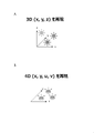
- FIG. 4 is a diagram for explaining congestion adjustment contradiction; 2A and 2B are diagrams for explaining a depth reproduction method.
- a diagram for explaining the light field (cited from the paper: Marc Levoy and Pat Hanrahan, 1996, “Light Field Rendering”).
- 4A and 4B are diagrams for explaining viewpoints.
- 5A and 5B are diagrams for explaining viewpoints.
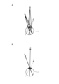
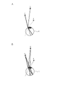
- 6A and 6B are diagrams for explaining the principle of focus adjustment blurring in the case of two viewpoints.
- FIG. 10 is a diagram for explaining the principle of focus adjustment blurring in the case of multiple viewpoints;
- FIG. 2 is a diagram schematically showing integral imaging (cited from the paper: M.G. Lippman, 1908, "Epreuves Reversibles Donnant la Sensation du Relief”).
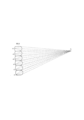
- FIG. 10 is a diagram showing a virtual pixel size of a light field
- FIG. 4 is a diagram for explaining an example of generating viewpoint groups using a single light field reproducing device
- FIG. 10 is a diagram for explaining an example of generating viewpoint groups using two light field reproduction devices
- 12A and 12B are diagrams for explaining an example using a single ride field reproduction device and eye tracking device.
- 13A and 13B are diagrams for explaining the size of the eyebox when only a single light field reproducing device is used.
- 14A and 14B are diagrams for explaining the size of the eyebox when using a single light field reproducing device and eye tracking device.
- FIG. 4 is a diagram for explaining an example of generating viewpoint groups using a single light field reproducing device
- FIG. 10 is a diagram for explaining an example of generating viewpoint groups using two light field reproduction devices
- 12A and 12B are diagrams for explaining an example using a single ride field reproduction device and eye tracking device.
- 13A and 13B are diagrams for explaining the size of
- FIG. 10 is a diagram for explaining a method of calculating a shift amount of a center position of an element image; It is a figure showing composition of a display of Example 1 of one embodiment of this art. It is a figure which shows the structure of the display apparatus of Example 2 of one embodiment of this technique. It is a figure which shows the structure of the display apparatus of Example 3 of one embodiment of this technique. It is a figure which shows the structure of the display apparatus of Example 4 of one embodiment of this technique. It is a figure which shows the structure of the display apparatus of Example 5 of one Embodiment of this technique. It is a figure which shows the structure of the display apparatus of Example 6 of one embodiment of this technique. It is a block diagram showing the function of the display device of Example 6 of one embodiment of the present technology.
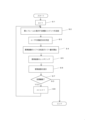
- FIG. 10 is a flowchart for explaining the operation of the display device of Example 6 of one embodiment of the present technology
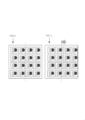
- FIG. 13 is a diagram for explaining shift of elemental images in the display device of Example 6 of one embodiment of the present technology
- FIG. 13 is a diagram for explaining shift of elemental images in the display device of Example 6 of one embodiment of the present technology
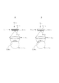
- 26A and 26B are diagrams for explaining a display device of a comparative example
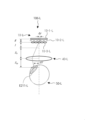
- 27A to 27C are diagrams for explaining the action of the display device having the eye tracking device. It is a figure which shows the structure of the display apparatus of Example 7 of one Embodiment of this technique. It is a figure which shows the structure of the display apparatus of Example 8 of one Embodiment of this technique.
- FIG. 20 is a diagram showing the configuration of a display device of Example 10 of an embodiment of the present technology; It is a figure which shows the structure of the display apparatus of Example 11 of one Embodiment of this technique.
- FIG. 20 is a diagram showing the configuration of a display device of Example 12 of an embodiment of the present technology;
- FIG. 20 is a diagram illustrating the configuration of a display device of Example 13 of an embodiment of the present technology;
- FIG. 20 is a diagram showing a configuration of a display device of Example 14 of an embodiment of the present technology;
- Display device of one embodiment of the present technology (1) Display device of Example 1 (2) Display device of Example 2 (3) Display device of Example 3 (4) Display device of Example 4 (5) Example Display device of 5 (6) Display device of Example 6 (7) Display device of Example 7 (8) Display device of Example 8 (9) Display device of Example 9 (10) Display device of Example 10 ( 11) Display device of Example 11 (12) Display device of Example 12 (13) Display device of Example 13 (14) Display device of Example 14 4. Modified example of this technology
- HMDs head-mounted displays
- VAC is known to cause 3D motion sickness, asthenopia, headaches, etc., and there are restrictions on age and usage time.
- VAC As a method to solve VAC, there is a contradiction in convergence adjustment, such as the light field method and super multi-view method that reproduce light ray information, the hologram method that reproduces light wavefront, and the multiple virtual image plane method that multiplexes virtual image planes temporally and spatially.
- Various techniques have been reported to solve the problem.
- the light field method is a method of reproducing a total of 4-dimensional information of the 2-dimensional position and 2-dimensional direction of light rays.
- an HMD When used as an HMD, it is theoretically possible to reproduce the five-dimensional information by representing the information of the five-dimensional eye visually, and to construct a virtual space that is extremely close to the real space.
- a huge amount of data is required to reproduce four-dimensional light ray information, and the current technology lacks hardware performance such as display resolution, and computer performance such as transmission capability and calculation capability.
- the density of the reproduced light beam is in a trade-off relationship with the size of the eyebox, making optical design in consideration of eyeball rotation, HMD hanging deviation, and the like difficult.
- Patent Document 1 Japanese Patent Publication No. 2017-515162 is a technology related to AR, and displays a light field reproduced through an eyepiece superimposed on the real world.
- the light field is reproduced using integral imaging, which consists of a display that displays elemental images and a microlens array.
- integral imaging which consists of a display that displays elemental images and a microlens array.
- Reference 1 Japanese Patent Publication No. 2015-5212978 is a technology related to VR, and displays a light field reproduced through an eyepiece.
- the light field is reproduced using integral imaging, which consists of LED emitters displaying elemental images and microlens arrays.
- the LED emitter has an array of tiny LED light sources and can be used as a display.
- High-resolution video can be displayed by moving the LED emitters in a direction perpendicular to the optical axis at high speed in synchronization with the displayed image.
- a drive unit is required, and there is a risk that the system will become large and complicated.
- a high refresh rate is required to display video in a time-division manner, which may result in enormous transmission costs and computational costs.
- Reference 2 Japanese Patent Publication No. 2020-513595
- viewpoints are generated at different positions on the pupil plane of both eyes of the user in a time division manner.
- the user can visually recognize an image with depth.
- This method achieves high viewpoint density and high resolution by distributing information in the time direction.
- spatial modulators that can achieve high refresh rates are limited, the final refresh rate can be low, and transmission and computation costs can be enormous.
- Reference 3 (National Publication No. 2020-520475) is a technology related to Near Eye Display that reproduces a light field by integral imaging, which is composed of a display that displays elemental images and a microlens array. Viewpoint density and resolution are in a trade-off relationship with respect to the width of the eyebox, which is the range in which viewpoints are generated.
- This technology uses eye tracking to reproduce the light field according to the position of the eyes, thereby narrowing the range of the eye box for each frame and improving the resolution and viewpoint density.
- the scope of application indicated by this technology is limited to near-eye displays, and cannot be applied as is to HMDs that use eyepiece optical elements (eg, eyepiece lenses).
- VAC can be solved by using the light field, but since the amount of information to be reproduced is large, the viewpoint density, resolution, eye box, refresh rate, transmission cost, or calculation cost There are still issues such as the sacrifice of Also, by using eye tracking, the eyebox range can be determined efficiently for each frame, but the technique of Reference 3 cannot be used as is for the HMD targeted by this technique.
- the inventor developed the display device and display method of this technology with the aim of further improving the viewpoint density and resolution, further realizing a sense of immersion, and further reducing the rendering cost and transmission cost.
- depth reproduction methods in stereoscopic display include a 3D reproduction method that reproduces 3D (x, y, z) shown in FIG. 2A and a 4D reproduction method that reproduces 4D (x, y, u, v) shown in FIG. 2B. method.
- the amount of information can be limited to (x, y, z), and high depth reproducibility and high resolution can be achieved, but there is a concern that the apparatus will become large in order to reproduce defocus.
- Specific examples of the 3D reproduction method include, for example, a variable virtual image position method and a multiple virtual image plane method.
- the 4D reproduction method out-of-focus blur, BRDF (Bidirectional Reflectance Distribution Function), and specular component (specular reflection component) are reproduced, but the amount of information is large, and there is a trade-off between high depth reproducibility and high resolution.
- Examples of the 4D reproduction method include a light field method, a hologram method, and the like.
- This technology uses the light field method.
- the intensity L of a ray is expressed by four parameters (u, v, s, t) representing the position and direction. Below you can reproduce the 4th dimension.
- the chief rays from points P, Q, and R are condensed at the center of the pupil of the eye E (an optical path equivalent to Maxell's vision), and the convergence A light spot can be regarded as one viewpoint.
- the converging point can also be regarded as one viewpoint.
- FIG. 6A since the eye E is focused on the object P, the retinal image P′ of the object P is not blurred, and the retinal image Q′′ of the object Q is Blur occurs (the image Q" is a double image).
- FIG. 6B the eye E is focused on the object Q, so the image Q' of the object Q on the retina is blurred. is not generated, and the image P'' of the object P on the retina is blurred (the image P'' is a double image).
- Fig. 8 shows a method of reproducing the light field by integral imaging. Both horizontal and vertical parallaxes can be represented by forming an image of light rays from each point a on the photographic plate at the viewpoint A by the corresponding lens of the microlens array MLA. A light field can be reproduced by integral imaging even if an elemental image display device (two-dimensional image display device) is used instead of the photographic dry plate.
- an elemental image display device two-dimensional image display device
- dv is the pitch of adjacent viewpoints
- PMLA is the pitch of the microlenses
- fep is the focal length of the eyepiece EP.
- PEI represents the pitch of the elemental images.
- the formula (3) above is quoted from the following paper. Hekun Huang and Hong Hua 2019, ⁇ Generalized methods and strategies for modeling and optimizing the optics of 3D head-mounted light field displays ⁇
- the light field reproducing device LFPD includes, as shown in FIG. 10, an elemental image display device EIDD, a microlens array MLA, and an eyepiece EP.
- the elemental image display device EIDD emits, for example, three light beam groups RG1, RG2, and RG3. Each ray group includes, for example, three rays.
- the three rays of the group of rays RG1 emitted from the elemental image display device EIDD are converged at three different viewpoints POV through the corresponding lenses of the microlens array MLA and the eyepiece EP in this order. be illuminated.
- the three light rays of the light ray group RG2 emitted from the elemental image display device EIDD are converged at three different viewpoints POV through the corresponding lenses of the microlens array MLA and the eyepiece EP in this order. be illuminated.
- the three light rays of the light ray group RG3 emitted from the elemental image display device EIDD are converged at three different viewpoints POV through the corresponding lenses of the microlens array MLA and the eyepiece EP in this order. be illuminated.
- each viewpoint POV is generated by corresponding rays of each ray group. Accordingly, when the user's eye E is positioned at each viewpoint POV, the user can visually recognize a three-dimensional image in which the light rays of each light group are superimposed.
- the viewpoint group is generated using a single light field reproducing device, in order to increase the number of viewpoints and obtain high depth reproducibility, the three-dimensional image generated by the light field reproducing device (Light field) resolution has to be lowered.
- the first light field reproducing device LFPD1 includes an elemental image display device EIDD1, a microlens array MLA1, and an eyepiece EP.
- Elemental image display device EIDD1 emits, for example, three groups of light rays RG1-1, RG2-1, and RG3-1. Each ray group includes, for example, three rays.
- the second light field reproducing device LFPD2 includes an elemental image display device EIDD2, a microlens array MLA2, and an eyepiece EP.
- Elemental image display device EIDD2 emits, for example, three groups of light rays RG1-2, RG2-2, and RG3-2. Each ray group includes, for example, three rays.
- the three light rays of the light ray group RG1-1 emitted from the elemental image display device EIDD1 pass through the corresponding lens of the microlens array MLA1 and the eyepiece EP in this order to form three different light beams.
- the light is condensed at the viewpoint POV1.
- the three light rays of the light ray group RG2-1 emitted from the elemental image display device EIDD1 pass through the corresponding lens of the microphone lens array MLA1 and the eyepiece EP in this order to form three different light beams.
- the light is condensed at the viewpoint POV1.
- the three light rays of the light ray group RG3-1 emitted from the elemental image display device EIDD1 pass through the corresponding lens of the microphone lens array MLA1 and the eyepiece EP in this order to form three different light beams.
- the light is condensed at the viewpoint POV1.
- each viewpoint POV1 is generated by corresponding light rays of each light group from the elemental image display device EIDD1. Accordingly, when the user's eye E is positioned at each viewpoint POV1, the user can visually recognize a three-dimensional image in which the light rays of each light group are superimposed.
- the three rays of the group of rays RG1-2 emitted from the elemental image display device EIDD2 pass through the corresponding lens of the microlens array MLA2 and the eyepiece EP in this order to form three different beams.
- the light is condensed at the viewpoint POV2.
- the three rays of the group of rays RG2-2 emitted from the elemental image display device EIDD2 pass through the corresponding lens of the microlens array MLA2 and the eyepiece EP in this order to produce three different rays.
- the light is condensed at the viewpoint POV2.
- the three rays of the group of rays RG3-2 emitted from the elemental image display device EIDD2 pass through the corresponding lens of the microlens array MLA2 and the eyepiece EP in this order to obtain three different rays.
- the light is condensed at the viewpoint POV2.
- each viewpoint POV2 is generated by corresponding light rays of each light group from the elemental image display device EIDD2. Accordingly, when the user's eye E is positioned at each viewpoint POV2, the user can visually recognize a three-dimensional image in which the light rays of each light group are superimposed.
- two light field reproducing devices are used to generate two corresponding viewpoint groups.
- high depth reproducibility can be obtained.
- each light ray of the light ray group RG emitted from the elemental image display device EIDD and passed through the microlens array MLA is condensed at a corresponding viewpoint in the vicinity of the eye E through the eyepiece EP. be done.
- the orientation of the eyeball E is detected by the eye tracking device ETD, and the display of the elemental image displayed by the elemental image display device EIDD is controlled according to the detection result. This makes it possible to increase the resolution of the three-dimensional image generated by the light field reproducing device LFPD without reducing the number of viewpoints.
- FIG. 12A shows a state in which the eyebox EB2 when the elemental image EI2 is displayed is shifted by the entire image with respect to the eyebox EB1 when the elemental image EI1 is displayed.
- FIG. 12B shows a state in which the elemental image EI2 is slightly shifted (for example, less than one pixel) with respect to the elemental image EI1.
- f ep is the focal length of the eyepiece EP.
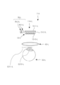
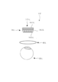
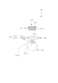
- FIG. 16 is a schematic diagram showing the basic configuration of the display device 101 of Example 1.
- the display device 101 is composed of a display device 101-L for the left eye and a display device 101-R for the right eye.
- the display devices 101-L and 101-R are laid out symmetrically.
- the display device 101 is, for example, a head-mounted display device (HMD) that is worn on the user's head.
- the display device 101 is used, for example, to provide VR to the user.
- HMD head-mounted display device
- the display device 101 has a plurality of (for example, two) three-dimensional image display devices corresponding to each of the user's eyes. Specifically, the display device 101-L has first and second three-dimensional image display devices 10-L and 11-L corresponding to the user's left eye 50-L. The display device 101-R has first and second three-dimensional image display devices 10-R and 11-R corresponding to the user's right eye 50-R.
- the display device 101 generates viewpoint groups for the eyes corresponding to both eyes of the user by groups of light rays emitted from each of a plurality of (for example, two) three-dimensional image display devices corresponding to each of the eyes of the user.
- a viewpoint group generation system is provided.
- the viewpoint group generation system of the display device 101-L generates a plurality of viewpoints S10-L for the user's left eye 50-L by a group of light rays emitted from the first three-dimensional image display device 10-L. while generating a first viewpoint group including Generate groups.
- a viewpoint group generation system of the display device 101-R generates a first three-dimensional image display device 10-R including a plurality of viewpoints S10-R for the user's right eye 50-R by a group of light rays emitted from the first three-dimensional image display device 10-R.
- a group of viewpoints is generated, and a second group of viewpoints including a plurality of viewpoints S11-R for the user's right eye 50-R is generated by a group of rays emitted from the second three-dimensional image display device 11-R. .
- Each component of the viewpoint group generation system of the display devices 101-L and 101-R is provided, as an example, in a spectacle frame worn on the user's head.
- the first three-dimensional image display device 10-L of the display device 101L includes an elemental image display device 10-1-L and a microlens array 10-3-L.
- a second three-dimensional image display device 11-L of the display device 101L includes an elemental image display device 11-1-L and a microlens array 11-3-L.
- a first three-dimensional image display device 10-R of the display device 101R includes an elemental image display device 10-1-R and a microlens array 10-3-R.
- a second three-dimensional image display device 11-R of the display device 101R includes an elemental image display device 11-1-R and a microlens array 11-3-R.
- each three-dimensional image display device is, as an example, a light field reproduction device that reproduces a light field by the integral imaging method.
- Each elemental image display device is a two-dimensional image display device, and includes, for example, a self-luminous display element.
- the display element may have, for example, an LED (Light Emitting Diode) array or an OLED (Organic Light Emitting Diode) array.
- Each elemental image display device is a two-dimensional image display device, and may include, for example, a light source and a spatial modulator.
- the light source may be, for example, an LED (Light Emitting Diode), an OLED (Organic Light Emitting Diode), an organic EL (Electro Luminescence) element, a cold cathode tube, or the like.
- the spatial modulator may be a liquid crystal element (for example, LCD: Liquid Crystal Display).
- the spatial modulator may be of a transmissive type (for example, a transmissive liquid crystal element).
- the first three-dimensional image display device 10-L of the display device 101L has an aperture array 10-2-L arranged between the elemental image display device 10-1-L and the microlens array 10-3-L. Including further.
- the second three-dimensional image display device 11-L of the display device 101L has an aperture array 11-2-L arranged between the elemental image display device 11-1-L and the microlens array 11-3-L. Including further.
- the first three-dimensional image display device 10-R of the display device 101R has an aperture array 10-2-R arranged between the elemental image display device 10-1-R and the microlens array 10-3-R. Including further.
- the second three-dimensional image display device 11-R of the display device 101L has an aperture array 11-2-R arranged between the elemental image display device 11-1-R and the microlens array 11-3-R. Including further.
- Each light ray of a group of light rays emitted from each elemental image display device of the first and second three-dimensional image display devices 10-L and 11-L of the display device 101L passes through a corresponding aperture array to a corresponding microlens. After being incident on the array and condensed at countless points forming a 3D space, the light is incident on the first optical system, which will be described later.
- Each light ray of a group of light rays emitted from each elemental image display device of the first and second three-dimensional image display devices 10-R and 11-R of the display device 101R passes through a corresponding aperture array to a corresponding microlens. After being incident on the array and condensed at countless points forming a 3D space, the light is incident on a second optical system, which will be described later.
- the plurality of three-dimensional image display devices of the display device 101-L include at least one pair (for example, one group) have.
- the first emission direction which is the emission direction of the group of light rays from the first three-dimensional image display device 10-L
- the second emission direction which is the emission direction of the group of rays from L, is substantially orthogonal to the first emission direction.
- the plurality of three-dimensional image display devices of the display device 101-R includes at least one pair (for example, one group) have.
- the third emission direction which is the emission direction of the group of rays from the first three-dimensional image display device 10-R, faces the right eye 50-R
- the second three-dimensional image display device 11-R faces the right eye 50-R.
- the fourth exit direction which is the exit direction of the group of rays from R, is substantially orthogonal to the third exit direction.
- the viewpoint group generation system of the display device 101-L includes a first optical system that guides light rays from each of the first and second three-dimensional image display devices 10-L and 11-L.
- the first optical system includes a first group of rays from the first three-dimensional image display device 10-L and a second group of rays from the second three-dimensional image display device 11-L. It has an optical element 30-L that aligns the direction of travel.
- the optical element 30-L aligns the traveling directions of the incident first and second groups of light rays in the direction toward the left eye 50-L.
- the optical element 30-L is, for example, a beam splitter.
- the beam splitter is, for example, a half mirror.
- a polarization beam splitter for example, may be used as the beam splitter. However, in this case, it is necessary to make the polarization directions of the groups of light beams from the first and second three-dimensional image display devices 10-L and 11-L orthogonal to each other.
- a group of non-polarized light rays may be made incident on the polarizing beam splitter.
- the polarizing beam splitter transmits or reflects 50% of the light group from each three-dimensional image display device.
- the first optical system further has an eyepiece optical element 40-L into which the first and second groups of rays from the optical element 30-L are incident.
- the eyepiece optical element 40-L is, for example, an eyepiece lens.
- the first optical system out of the first group of light rays from the first three-dimensional image display device 10-L, those transmitted through the optical element 30-L and passed through the eyepiece optical element 40-L are viewed from a plurality of viewpoints S10-L. A first set of viewpoints containing L is generated.
- the rays reflected by the optical element 30-L and passed through the eyepiece optical element 40-L are reflected from the plurality of viewpoints S11-L.
- a second set of viewpoints including L is generated.
- the viewpoint group generation system of the display device 101-R includes a second optical system that guides light rays from each of the first and second three-dimensional image display devices 10-R and 11-R.
- the second optical system includes a first group of rays from the first three-dimensional image display device 10-R and a second group of rays from the second three-dimensional image display device 11-R. It has an optical element 30-R that aligns the direction of travel.
- the optical element 30-R aligns the traveling directions of the incident first and second groups of rays in the direction toward the right eye 50-R.
- the optical element 30-R is, for example, a beam splitter.
- the beam splitter is, for example, a half mirror.
- a polarization beam splitter for example, may be used as the beam splitter. However, in this case, it is necessary to make the polarization directions of the groups of light beams from the first and second three-dimensional image display devices 10-R and 11-R orthogonal to each other.
- a group of non-polarized light rays may be made incident on the polarizing beam splitter.
- the polarizing beam splitter transmits or reflects 50% of the light group from each three-dimensional image display device.
- the second optical system further has an eyepiece optical element 40-R into which the first and second groups of rays from the optical element 30-R are incident.
- the eyepiece optical element 40-R is, for example, an eyepiece lens.
- the second optical system among the first group of light rays from the first three-dimensional image display device 10-R, those transmitted through the optical element 30-R and passed through the eyepiece optical element 40-R are projected from a plurality of viewpoints S10-R. A first set of viewpoints containing R is generated.
- the rays reflected by the optical element 30-R and passed through the eyepiece optical element 40-R are reflected from a plurality of viewpoints S11- A second set of viewpoints including R is generated.
- the first and second viewpoint groups generated by the display device 101-L do not overlap. That is, the first and second viewpoint groups are generated at different positions by the display device 101-L. Specifically, a viewpoint S11-L of the second viewpoint group is generated between two neighboring viewpoints S10-L of the first viewpoint group. Specifically, viewpoints S10-L of the first viewpoint group and viewpoints S11-L of the second viewpoint group are alternately arranged and generated. Note that the first viewpoint group and the second viewpoint group need not overlap, and the viewpoint S10-L of the first viewpoint group and the viewpoint S11-L of the second viewpoint group do not have to be alternately generated.
- the plurality of viewpoints S10-L of the first viewpoint group are aligned at a predetermined pitch
- the plurality of viewpoints S11-L of the second viewpoint group are aligned at the predetermined pitch, so that the adjacent viewpoints S10-L and S11
- the pitch of -L is constant, it is not limited to this.
- the pitches of adjacent viewpoints S10-L and S11-L may not be constant.
- the pitches of adjacent viewpoints S10-L and S11-L may be regular or random.
- first and second viewpoint groups generated by the display device 101-R do not overlap.
- the first and second viewpoint groups are generated at different positions by the display device 101-R. Specifically, viewpoints S10-R of the first viewpoint group and viewpoints S11-R of the second viewpoint group are alternately arranged and generated. Note that the first and second viewpoint groups need not overlap, and the viewpoints S10-R of the first viewpoint group and the viewpoints S11-R of the second viewpoint group do not have to be alternately generated.
- the plurality of viewpoints S10-R of the first viewpoint group are aligned at a predetermined pitch
- the plurality of viewpoints S11-R of the second viewpoint group are aligned at the predetermined pitch, so that the adjacent viewpoints S10-R and S11
- the pitch of -R is constant, it is not limited to this.
- the pitches of adjacent viewpoints S10-R and S11-R may not be constant.
- the pitches of adjacent viewpoints S10-R and S11-R may be regular or random.
- the display device 101-L generates at least two viewpoints S10-L and S11-L among the plurality of viewpoints forming the first and second viewpoint groups within the pupil diameter of the left eye 50-L.
- the display device 101-R generates at least two viewpoints S10-R and S11-R among the plurality of viewpoints forming the first and second viewpoint groups within the pupil diameter of the right eye 50-R.
- the first ray group emitted from the first three-dimensional image display device 10-L passes through the optical element 30-L and the eyepiece optical element 40-L in this order, and reaches the user's Incident to the left eye 50-L.
- the first light ray group generates a first viewpoint group including a plurality of viewpoints S10-L on the pupil plane of the left eye 50-L.
- the second ray group emitted from the second three-dimensional image display device 11-L passes through the optical element 30-L and the eyepiece optical element 40-L in this order, and reaches the user's Incident to the left eye 50-L.
- the second light ray group generates a second viewpoint group including a plurality of viewpoints S11-L on the pupil plane of the left eye 50-L.
- the first light ray group emitted from the first three-dimensional image display device 10-R passes through the optical element 30-R and the eyepiece optical element 40-R in this order, and reaches the user's Incident to the right eye 50-R.
- the first light ray group generates a first viewpoint group including a plurality of viewpoints S10-R on the pupil plane of the right eye 50-R.
- the second group of light rays emitted from the second three-dimensional image display device 11-R passes through the optical element 30-R and the eyepiece optical element 40-R in this order, and reaches the user's Incident to the right eye 50-R.
- the second light ray group generates a second viewpoint group including a plurality of viewpoints S11-R on the pupil plane of the right eye 50-R.
- a display method is provided that generates a set of viewpoints.
- the viewpoint density of the viewpoint group generated by each 3D image display device can be reduced. As a result, it is possible to improve the resolution of the light field reproduced by each three-dimensional image display device.
- the display device 101 of Example 1 is a relatively simple HMD that does not limit the field of view and does not have a driving unit or the like, as compared with the above-mentioned Patent Document 1 and Reference Documents 1 to 3 as HMDs that improve VAC.
- the configuration can achieve both high viewpoint density and high resolution.
- the resolution of the image to be displayed is at most about double, and transmission costs and calculation costs can be suppressed without affecting the refresh rate.
- a three-dimensional image can be displayed with high resolution and high depth reproducibility without limiting the field of view.
- FIG. 17 is a schematic diagram showing the basic configuration of the display device 102 of Example 2.
- the display device 102 is composed of a left-eye display device 102-L and a right-eye display device 102-R.
- the display device 102-L and the display device 102-R are laid out symmetrically.
- the display device 102 is, for example, a head-mounted display device (HMD) worn on the user's head.
- Display device 102 is used, for example, to provide VR to a user.
- HMD head-mounted display device
- the optical system (first optical system) of the display device 102-L has a first relay optical system 20-L and a second relay optical system 21-L.
- the display device 101 of Example 1 except that the optical system (second optical system) of the display device 102-R has a first relay optical system 20-R and a second relay optical system 21-R. has the same configuration as
- the first relay optical system 20-L is arranged between the first three-dimensional image display device 10-L and the optical element 30-L, and the first relay optical system 20-L is arranged between the first three-dimensional image display device 10-L and the optical element 30-L. Generate an intermediate image of the rays.
- the second relay optical system 21-L is arranged between the second three-dimensional image display device 11-L and the optical element 30-L, and the second relay optical system 21-L is arranged between the second three-dimensional image display device 11-L and the optical element 30-L. Generate an intermediate image of the rays.
- the first relay optical system 20-R is arranged between the first three-dimensional image display device 10-R and the optical element 30-R, and the first relay optical system 20-R is arranged between the first three-dimensional image display device 10-R and the optical element 30-R. Generate an intermediate image of the rays.
- the second relay optical system 21-R is arranged between the second three-dimensional image display device 11-R and the optical element 30-R, and the second relay optical system 21-R is arranged between the second three-dimensional image display device 11-R and the optical element 30-R. Generate an intermediate image of the rays.
- each relay optical system is, for example, composed of a relay lens including at least one lens element.
- the first group of light rays emitted from the first three-dimensional image display device 10-L passes through the first relay optical system 20-L, the optical element 30-L, and the eyepiece optical element 40- and L in this order, and enters the user's left eye 50-L.
- the first light ray group generates a first viewpoint group including a plurality of viewpoints S10-L on the pupil plane of the left eye 50-L.
- the second group of light rays emitted from the second three-dimensional image display device 11-L passes through the second relay optical system 21-L, the optical element 30-L, and the eyepiece optical element 40- and L in this order, and enters the user's left eye 50-L.
- the second light ray group generates a second viewpoint group including a plurality of viewpoints S11-L on the pupil plane of the left eye 50-L.
- the first group of light rays emitted from the first three-dimensional image display device 10-R passes through the first relay optical system 20-R, the optical element 30-R, and the eyepiece optical element 40- R and , in this order, and enters the user's right eye 50-R.
- the first light ray group generates a first viewpoint group including a plurality of viewpoints S10-R on the pupil plane of the right eye 50-R.
- the second group of light rays emitted from the second three-dimensional image display device 11-R passes through the second relay optical system 21-R, the optical element 30-R, and the eyepiece optical element 40- R and , in this order, and enters the user's right eye 50-R.
- the second light ray group generates a second viewpoint group including a plurality of viewpoints S11-R on the pupil plane of the right eye 50-R.
- a display method is provided that generates a set of viewpoints.
- the display device 102-L may have only one of the first and second relay optical systems 20-L and 21-L.
- the display device 102-R may have only one of the first and second relay optical systems 20-R, 21-R.
- FIG. 18 is a schematic diagram showing the basic configuration of the display device 103 of Example 3.
- the display device 103 is composed of a left-eye display device 103-L and a right-eye display device 103-R.
- the display device 103-L and the display device 103-R are laid out symmetrically.
- the display device 103 is, for example, a head-mounted display device (HMD) that is worn on the user's head.
- the display device 103 is used, for example, to provide VR to the user.
- HMD head-mounted display device
- the plurality of three-dimensional image display devices of the display device 103-L corresponding to the left eye 50-L are the first and second three-dimensional image display devices.
- a plurality of sets (for example, two sets) are provided, and the plurality of 3D image display devices of the display device 103-R corresponding to the right eye 50-R are the sets of the first and second 3D image display devices. It has multiple sets (for example, two sets).
- the display device 103-L includes a set of first and second three-dimensional image display devices 10-L and 12-L, and first and second three-dimensional image display devices 13-L and 11- L pairs.
- the display device 103-R includes a set of first and second three-dimensional image display devices 10-R and 12-R and a set of first and second three-dimensional image display devices 13-R and 11-R. have.
- the second three-dimensional image display device 12-L of the display device 103L includes, for example, an elemental image display device 12-1-L, a microlens array 12-3-L, and an aperture array arranged therebetween. 10-2-L and.
- the first three-dimensional image display device 13-L of the display device 103L includes, for example, an elemental image display device 13-1-L, a microlens array 13-3-L, and an aperture array arranged therebetween. 13-2-L and.
- the first three-dimensional image display device 12-R of the display device 103R includes, for example, an elemental image display device 12-1-R, a microlens array 12-3-R, and an aperture array 12 arranged therebetween. -2-R.
- the second three-dimensional image display device 13-R of the display device 103L includes, for example, an elemental image display device 13-1-R, a microlens array 13-3-R, and an aperture array 13 arranged therebetween. -2-R.
- the first optical element for aligning the traveling directions of the groups of light rays emitted from each of the first and second three-dimensional image display devices serves as a plurality of sets of first and second three-dimensional image displays. provided for each set of devices.
- a first optical element 31-L is provided for a set of the first and second three-dimensional image display devices 10-L and 12-L, and the first and second three-dimensional image display devices
- a first optical element 32-L is provided for the set of devices 13-L, 11-L.
- the display device 103-L has a first relay optical system 20-L between the first three-dimensional image display device 10-L and the first optical element 31-L, and is a second three-dimensional image display device.
- a second relay optical system 22-L is provided between 12-L and the first optical element 31-L, and a relay optical system 22-L is provided between the first three-dimensional image display device 13-L and the first optical element 32-L. It has a first relay optical system 23-L and a second relay optical system 21-L between the second three-dimensional image display device 11-L and the second optical element 32-L.
- the first optical element for aligning the traveling directions of the groups of light rays emitted from each of the first and second three-dimensional image display devices is provided with a plurality of sets of first and second three-dimensional image displays. provided for each set of devices.
- a first optical element 31-R is provided for a set of the first and second three-dimensional image display devices 10-R and 12-R, and the first and second three-dimensional image display
- a first optical element 32-R is provided for the set of devices 13-R, 11-R.
- the display device 103-R has a first relay optical system 20-R between the first three-dimensional image display device 10-R and the first optical element 31-R, and is a second three-dimensional image display device.
- a second relay optical system 22-R is provided between 12-R and the first optical element 31-R, and a relay optical system 22-R is provided between the first three-dimensional image display device 13-R and the first optical element 32-R. It has a first relay optical system 23-R and a second relay optical system 21-R between the second three-dimensional image display device 11-R and the second optical element 32-R.
- the display device 103-L displays the traveling direction of one ray group pair including the first and second ray groups from one first optical element among a plurality of (for example, two) first optical elements,
- the optical system further includes a second optical element for aligning the traveling directions of the first and other light ray group pairs from the first optical element and intersecting with the traveling directions of other light ray group pairs including the first and second light ray groups.
- the traveling direction of one light ray group pair including the first and second light ray groups from the first optical element 31-L and the first light ray group from the first optical element 32-L and the traveling directions of other ray group pairs including the second ray group intersect (for example, substantially orthogonal), and the optical system has a second optical element 30-L that aligns the traveling directions of the one and other ray group pairs.
- the display device 103-R displays the traveling direction of one ray group pair including the first and second ray groups from one first optical element among a plurality of (for example, two) first optical elements, and the traveling direction of the other first optical element.
- the optical system further includes a second optical element for aligning the traveling directions of the first and other light ray group pairs from the first optical element and intersecting with the traveling directions of other light ray group pairs including the first and second light ray groups. have.
- the traveling direction of one light ray group pair including the first and second light ray groups from the first optical element 31-R and the direction of travel of the first light ray group from the first optical element 32-R and the traveling directions of other ray group pairs including the second ray group intersect (for example, substantially orthogonal), and the optical system has a second optical element 30-R that aligns the traveling directions of the one and other ray group pairs.
- each of the first optical elements and each of the second optical elements is, for example, the aforementioned beam splitter (eg, half mirror, polarization beam splitter, etc.).
- the aforementioned beam splitter eg, half mirror, polarization beam splitter, etc.
- the optical system of the display device 103-L is arranged between the first optical element 31-L and the second optical element 30-L, and is positioned between the first and second groups of light rays from the first optical element 31-L.
- An image-generating relay optical system 24-L disposed between the first optical element 32-L and the second optical element 30-L, for receiving first and second groups of rays from the first optical element 32-L. and a relay optical system 25-L for generating an intermediate image of .
- the optical system of the display device 103-R is arranged between the first optical element 31-R and the second optical element 30-R, and the optical system of the display device 103-R is arranged between the first and second groups of light rays from the first optical element 31-R.
- An image-generating relay optical system 24-R disposed between the first optical element 32-R and the second optical element 30-R, for receiving first and second groups of rays from the first optical element 32-R. and a relay optical system 25-R for generating an intermediate image of .
- each relay optical system is, for example, composed of a relay lens including at least one lens element.
- the optical system of the display device 103-L further has an eyepiece optical element 40-L (for example, an eyepiece lens) into which the first and second groups of rays from the second optical element 30-L are incident.
- an eyepiece optical element 40-L for example, an eyepiece lens
- the optical system of the display device 103-R further has an eyepiece optical element 40-R (for example, an eyepiece lens) into which the first and second groups of rays from the second optical element 30-R are incident.
- an eyepiece optical element 40-R for example, an eyepiece lens
- the first light beam group emitted from the first three-dimensional image display device 10-L passes through the first relay optical system 20-L, the first optical element 31-L, and the relay optical system. 24-L, the second optical element 30-L, and the eyepiece optical element 40-L in this order, and enter the user's left eye 50-L.
- the first light ray group generates a first viewpoint group including a plurality of viewpoint groups S10-L on the pupil plane of the left eye 50-L.
- the second light beam group emitted from the second three-dimensional image display device 12-L passes through the first relay optical system 22-L, the first optical element 31-L, and the relay optical system. 24-L, the second optical element 30-L, and the eyepiece optical element 40-L in this order, and enter the user's left eye 50-L.
- the second light ray group generates a second viewpoint group including a plurality of viewpoints S12-L on the pupil plane of the left eye 50-L.
- the first light beam group emitted from the first three-dimensional image display device 13-L passes through the first relay optical system 23-L, the first optical element 32-L, and the relay optical system. 25-L, the second optical element 30-L, and the eyepiece optical element 40-L in this order, and enter the user's left eye 50-L.
- the first light ray group generates a third viewpoint group including a plurality of viewpoints S13-L on the pupil plane of the left eye 50-L.
- the second light beam group emitted from the second three-dimensional image display device 11-L passes through the first relay optical system 21-L, the first optical element 32-L, and the relay optical system. 25-L, the second optical element 30-L, and the eyepiece optical element 40-L in this order, and enter the user's left eye 50-L.
- the second light ray group generates a fourth viewpoint group including a plurality of viewpoints S11-L on the pupil plane of the left eye 50-L.
- the first to fourth viewpoint groups are generated at different positions and do not overlap each other.
- a plurality of repeating units in FIG. 18, Only one unit is shown, but it is not limited to this.
- the first to fourth viewpoint groups may be generated such that the four viewpoints S10-L, S11-L, S12-L, and S13-L are arranged with another regularity, or may be generated randomly. may be generated so as to line up with
- the first light beam group emitted from the first three-dimensional image display device 10-R passes through the first relay optical system 20-R, the first optical element 31-R, and the relay optical system. 24-L, the second optical element 30-R, and the eyepiece optical element 40-R in this order, and enter the user's right eye 50-R.
- the first light ray group generates a first viewpoint group including a plurality of viewpoint groups S10-R on the pupil plane of the right eye 50-R.
- the second light beam group emitted from the second three-dimensional image display device 12-R passes through the first relay optical system 22-R, the first optical element 31-R, and the relay optical system. 24-R, the second optical element 30-R, and the eyepiece optical element 40-R in this order, and enters the user's right eye 50-R.
- the second light ray group generates a second viewpoint group including a plurality of viewpoints S12-R on the pupil plane of the right eye 50-R.
- the first light beam group emitted from the first three-dimensional image display device 13-R passes through the first relay optical system 23-R, the first optical element 32-R, and the relay optical system 25-R, the second optical element 30-R, and the eyepiece optical element 40-R in this order, and enter the user's right eye 50-R.
- the first light ray group generates a third viewpoint group including a plurality of viewpoints S13-R on the pupil plane of the right eye 50-R.
- the second light beam group emitted from the second three-dimensional image display device 11-R passes through the first relay optical system 21-R, the first optical element 32-R, and the relay optical system. 25-R, the second optical element 30-R, and the eyepiece optical element 40-R in this order, and enter the user's right eye 50-R.
- the second light ray group generates a fourth viewpoint group including a plurality of viewpoints S11-R on the pupil plane of the left eye 50-L.
- the first to fourth viewpoint groups are generated at different positions and do not overlap each other.
- a plurality of repeating units in FIG. 18, Only one unit is shown, but it is not limited to this.
- the first to fourth viewpoint groups may be generated such that the four viewpoints S10-R, S11-R, S12-R, and S13-R are arranged with another regularity, or may be generated randomly. may be generated so as to line up with
- light beams emitted from each of a plurality of sets (for example, two sets) of first and second three-dimensional image display devices corresponding to each of the user's eyes can be used to A display method is implemented that generates a set of viewpoints for corresponding eyes of the eye.
- arranging the relay optical system as shown in FIG. 18 may increase the size of the optical system. 3D image can be provided to the user.
- the optical path can be lengthened by the amount of the relay optical system, it becomes easy to install various filters on the optical path.
- the display device corresponding to each eye has four 3D image display devices, but is not limited to this, and has 3 3D image display devices. may have four or more three-dimensional image display devices.
- a relay optical system (for example, a relay lens) may be appropriately arranged between the three-dimensional image display device and the first optical element or between the first and second optical elements.
- a free-form surface prism that also functions as an eyepiece optical element may be used as the second optical element.
- This free-form surface prism also functions as a beam splitter as a second optical element and as an eyepiece lens as an eyepiece optical element.
- the display device 103-L may have only one of the relay optical systems 24-L and 25-L, or neither of them.
- the display device 103-R may have only one of the relay optical systems 24-R and 25-R, or neither of them.
- FIG. 19 is a schematic diagram showing the basic configuration of the display device 104 of Example 4.
- the display device 104 is composed of a display device 104-L for the left eye and a display device 104-R for the right eye.
- the display device 104-L and the display device 104-R are laid out symmetrically.
- the display device 104 is, for example, a head-mounted display device (HMD) worn on the user's head.
- the display device 104 is used, for example, to provide VR to the user.
- HMD head-mounted display device
- the display device 104-L includes the first and second three-dimensional image display devices 10-L and 12-L of the display device 103-L (see FIG. 18) of the third embodiment, and the first and second relay optical systems. 20-L, 22-L, the first optical element 31-L, and the relay optical system 24-L are replaced with a two-dimensional image display device 60-L for the left eye, and the second optical element 30-L and the eyepiece optical element 40-L are replaced with a free-form surface prism 41-L.
- the free-form surface prism 41-L transmits the group of rays from the two-dimensional image display device 60-L toward the left eye 50-L, and transmits the first and second groups of rays from the first optical element 32-L. It is reflected toward the left eye 50-L.
- the display device 104-R includes the first and second three-dimensional image display devices 10-R and 12-R of the display device 103-R of the third embodiment (see FIG. 18), and the first and second relay optical systems. 20-R, 22-R, the first optical element 31-R, and the relay optical system 24-R are replaced with a two-dimensional image display device 60-R for the right eye, and the second optical element 30-R and the eyepiece optical element 40-R are replaced with a free-form surface prism 41-R.
- the free-form surface prism 41-R transmits the group of rays from the two-dimensional image display device 60-R toward the right eye 50-R, and transmits the first and second groups of rays from the first optical element 32-R. It is reflected toward the right eye 50-R.
- Each two-dimensional image display device may display a two-dimensional image in at least a part of the visual field of the corresponding eye, or display a stereoscopic image using parallax between the left and right eyes.
- a parallax image may be displayed in at least a portion of the corresponding eye's field of view.
- the positional relationship between the configuration including the first and second three-dimensional image display devices and the first optical element and the two-dimensional image display device may be reversed with respect to each free-form surface prism.
- the first light beam group emitted from the first three-dimensional image display device 13-L passes through the first relay optical system 23-L, the first optical element 32-L, and the relay optical system. 25-L and the free-form surface prism 41-L in this order, and enters the user's left eye 50-L.
- the first light ray group generates a first viewpoint group including a plurality of viewpoints S13-L on the pupil plane of the left eye 50-L.
- the second light beam group emitted from the second three-dimensional image display device 11-L passes through the second relay optical system 21-L, the first optical element 32-L, and the relay optical system. 25-L and the free-form surface prism 41-L in this order, and enters the user's left eye 50-L.
- the second light ray group generates a second viewpoint group including a plurality of viewpoints S11-L on the pupil plane of the left eye 50-L.
- the first light beam group emitted from the first three-dimensional image display device 13-R passes through the first relay optical system 23-R, the first optical element 32-R, and the relay optical system 25-R and the free-form surface prism 41-R in this order, and enters the user's right eye 50-R.
- the first light ray group generates a first viewpoint group including a plurality of viewpoints S13-R on the pupil plane of the right eye 50-R.
- the second light beam group emitted from the second three-dimensional image display device 11-R passes through the second relay optical system 21-R, the first optical element 32-R, and the relay optical system. 25-R and the free-form surface prism 41-R in this order, and enters the user's right eye 50-R.
- the second light ray group generates a second viewpoint group including a plurality of viewpoints S11-R on the pupil plane of the right eye 50-R.
- each two-dimensional image display device displays a stereoscopic image using parallax between the left and right eyes in the entire field of view, and the corresponding first and second three-dimensional image display devices display light fields.
- a stereoscopic image (stereoscopic video) having depth information and induced focus adjustment may be displayed in a limited range in the center of the visual field of the corresponding eye.
- Images (videos) provided by the two-dimensional image display device and the three-dimensional image display device are superimposed and viewed by the user by passing through an optical system.
- a display method is provided that generates a set of viewpoints.
- the display device 104 of the fourth embodiment achieves a wide field of view and high resolution with a simpler configuration than the conventional HMD technology for improving the VAC described above, and can suppress rendering costs and transmission costs. It is possible.
- the human eye has the highest visual acuity in the central region of the visual field and poor vision elsewhere. Therefore, humans are insensitive to image quality deterioration in the visual field peripheral region.
- a 3D image (3D video) with high resolution and depth information is displayed in the center of the field of view, and a 2D image (2D video) with low resolution and a wide field of view is displayed in the entire field of view.
- a 3D image (3D video) with high resolution and depth information is displayed in the center of the field of view
- a 2D image (2D video) with low resolution and a wide field of view is displayed in the entire field of view.
- it is effective to limit the field of view range for depth reproducibility.
- by limiting the range in which the 3D image (3D video) is displayed it is possible to reduce the calculation cost and transmission cost required to render the 3D image (3D video).
- FIG. 20 is a schematic diagram showing the basic configuration of the display device 105 of Example 5.
- the display device 105 is composed of a display device 105-L for the left eye and a display device 105-R for the right eye.
- the display device 105-L and the display device 105-R are laid out symmetrically.
- the display device 105 is, for example, a head-mounted display device (HMD) worn on the user's head.
- the display device 105 is used, for example, to provide AR to the user.
- HMD head-mounted display device
- the display device 105 has the same configuration as the display device 104 of Example 4, except that the two-dimensional image display devices 60-L and 60-R (see FIG. 19) are not provided.
- the first light beam group emitted from the first three-dimensional image display device 13-L passes through the first relay optical system 23-L, the first optical element 32-L, and the relay optical system. 25-L and the free-form surface prism 41-L in this order, and enters the user's left eye 50-L.
- the first light ray group generates a first viewpoint group including a plurality of viewpoints S13-L on the pupil plane of the left eye 50-L.
- the second light beam group emitted from the second three-dimensional image display device 11-L passes through the second relay optical system 21-L, the first optical element 32-L, and the relay optical system. 25-L and the free-form surface prism 41-L in this order, and enters the user's left eye 50-L.
- the second light ray group generates a second viewpoint group including a plurality of viewpoints S11-L on the pupil plane of the left eye 50-L.
- the first light beam group emitted from the first three-dimensional image display device 13-R passes through the first relay optical system 23-R, the first optical element 32-R, and the relay optical system 25-R and the free-form surface prism 41-R in this order, and enters the user's right eye 50-R.
- the first light ray group generates a first viewpoint group including a plurality of viewpoints S13-R on the pupil plane of the right eye 50-R.
- the second light beam group emitted from the second three-dimensional image display device 11-R passes through the second relay optical system 21-R, the first optical element 32-R, and the relay optical system 25-R and the free-form surface prism 41-R in this order, and enters the user's right eye 50-R.
- the second light ray group generates a second viewpoint group including a plurality of viewpoints S11-R on the pupil plane of the right eye 50-R.
- a display method is provided that generates a set of viewpoints.
- the display device 105 According to the display device 105, the same effects as those of the display device 101 of the first embodiment can be obtained, and depth information generated by the first and second three-dimensional image display devices corresponding to each eye can be obtained.
- a stereoscopic image (stereoscopic image) that induces focus adjustment is displayed in a limited range such as the center of the visual field of the eye, and superimposed with light rays from the real world, thereby improving the see-through performance of the VAC. It is possible to provide a 3D augmented reality display with
- FIG. 21 is a schematic diagram showing the basic configuration of the display device 106 of the sixth embodiment.
- the display device 106 is composed of a display device 106-L for the left eye and a display device for the right eye.
- the display device 106-L and the display device for the right eye are laid out symmetrically, so the display device 106-L will be mainly described.
- the display device 106 is, for example, a head-mounted display device (HMD) worn on the user's head.
- Display device 106 is used, for example, to provide VR to a user.
- HMD head-mounted display device
- the display device 106-L includes a viewpoint group generation system and a line-of-sight detection system. Note that the display device for the right eye of the display device 106 may or may not have a line-of-sight detection system.
- the viewpoint group generation system of the display device 106-L has a three-dimensional image display device 10-L corresponding to the user's left eye 50-L and an optical system including an eyepiece optical element 40-L (for example, an eyepiece lens). Then, a group of viewpoints is generated for the left eye 50-L by a group of rays emitted from the three-dimensional image display device 10-L and passed through the optical system. At this time, it is preferable that at least two viewpoints among the plurality of viewpoints forming the viewpoint group are generated for the left eye 50-L.
- a step of generating viewpoint groups for corresponding eyes, wherein the step of generating viewpoint groups controls the generation position of the viewpoint groups based on the detection result of the detecting step. can do.
- the three-dimensional image display device 10-L of the display device 106-L includes, for example, an elemental image display device 10-1-L, an aperture array 10-2-L, and a microlens array 10-3-L. In preparation, the light field is reproduced by the integral imaging method.
- the line-of-sight detection system of the display device 106-L includes an eye-tracking device 70-L.
- the eye tracking device 70-L has a camera 70-1-L (light receiving section) that detects the direction (line of sight) of the left eye 50-L, and a light source 70-2-L (light source section) for illumination. .
- the camera 70-1-L and the light source 70-2-L are provided at the outer edge of the eyepiece optical element 40-L so as to face the left eye 50-L.
- the camera 70-1-L includes, for example, a light receiving element (imaging element) such as an image sensor.
- a light receiving element imaging element
- image sensor an image sensor
- the light source 70-2-L emits invisible light (for example, infrared light) as an example.
- invisible light for example, infrared light
- a light emitting diode, a laser, or the like can be used as the light source 70-2-L.
- the invisible light emitted from the light source 70-2-L and reflected by the left eye 50-L is imaged (received) by the camera 70-1-L.
- the "eye box” is the range in which the light field can be appropriately viewed, and the range in which the viewpoint is generated by the 3D image display device.
- the display device 106 uses an eye tracking device to generate an eye box in an appropriate range for each frame.
- symbols E211-L and E210-L indicate eyeboxes in different frames.
- integral imaging in order to change the position of the eyebox, it is necessary to change the image (video) displayed in the elemental image.
- the eyebox range can be restricted and narrowed to only the periphery of the pupil, and high resolution can be obtained while maintaining viewpoint density.
- FIG. 22 is a block diagram showing the functions of the display device 106.
- the viewpoint group generation system of the display device 106 further includes a control device 1000 that controls the viewpoint group generation positions based on the output of the eye tracking device 70-L, which is the detection result of the line-of-sight detection system.
- the control device 1000 is realized by hardware including a CPU, a chipset, etc., as an example.
- the control device 1000 has a main control section and an element image shift information calculation section 1000a.
- the element image shift information calculation unit 1000a calculates the shift information (shift direction and shift amount) of the element image from the orientation of the left eye 50-L based on the output of the eye tracking device 70-L, and uses the calculation result as the element image. Output to the display device 10-1-L. Elemental image display device 10-1-L generates an elemental image according to the shift information.
- the operation of the display device 106 (display method using the display device 106) will be described below with reference to FIG.
- the flow chart of FIG. 23 is based on a processing algorithm executed by the main control section of control device 1000 .
- the main control unit sets 1 to n.
- the main control unit determines the video content to be displayed in the n-th frame.
- the main control unit identifies the user's line of sight direction. Specifically, the main control unit identifies the orientation (line-of-sight direction) of the left eye 50-L of the user from the output of the eye-tracking device 70-L, and converts the identified orientation of the left eye 50-L into the element image. It is sent to the shift information calculation unit 1000a.
- the element image shift information calculation unit 1000a calculates the shift direction and shift amount of the element image. Specifically, the elemental image shift information calculation unit 1000a calculates the elemental image shift direction and shift amount so that an eyebox is generated at a position corresponding to the orientation of the identified left eye 50-L. For example, in a certain frame, when generating a viewpoint in the range of the eye box E210-L shown in FIG. Display Y310-L. In addition, when generating a viewpoint in the range of the eyebox E211-L shown in FIG. 21 in another certain frame, for example, an element image Y311-L shifted from the element image Y310-L as shown in FIG. 24 is displayed. .
- each parameter in the above equation (4) is as shown in FIG. Although the above equation (4) is shown only for the y direction, the same is true for the x direction.
- the amount and direction of shifting the elemental image can be determined.
- the main control unit renders the element images. Specifically, for example, the main control unit shifts the element image Y311-L in the amount and direction represented by the above formula (4) with respect to the element image Y310-L, and renders the video data. Generate.
- the main control unit displays the element image. Specifically, the main control unit drives the elemental image display device 10-1-L based on the video data generated in step S5 to display the elemental image. As a result, the light field is reproduced and, for example, multiple viewpoints are generated within the range of the eyebox E211-L (see FIG. 25).
- step S7 the main control unit determines whether or not to continue the process. Specifically, the main control unit determines not to continue processing when the display device 106 is powered off, and otherwise determines to continue processing. If the determination in step S7 is affirmative, the process proceeds to step S8, and if the determination is negative, the flow ends.
- step S8 the main control unit increments n. That is, the series of operations of steps S2 to S7 are performed in the next frame as well. After step S8 is executed, the process returns to step S2.
- a three-dimensional image can be displayed with high resolution and high depth reproducibility without limiting the field of view.
- the image display device 108-L of the comparative example shown in FIGS. 26A and 26B includes a three-dimensional image display device 10-L and an eyepiece optical element 40-L (for example, an eyepiece lens). If an eye tracking device is not used, it is necessary to take into account eyeball rotation, HMD hanging misalignment, and the like, and to ensure a wide eye box range.
- the user's left eye 51-L faces forward and the pupil is within the eyebox range E220-L, so the user can normally view the light field.
- FIG. 26A the user's left eye 51-L faces forward and the pupil is within the eyebox range E220-L, so the user can normally view the light field.
- FIG. 26A the user's left eye 51-L faces forward and the pupil is within the eyebox range E220-L, so the user can normally view the light field.
- the user's left eye 51-L is rotated and looks to the left, but since the eyebox range E220-L is widened, the pupil is within the eyebox range and the user sees the light field can be viewed normally.
- the eyebox size is large, it is not possible to improve the light field resolution while maintaining the viewpoint density.
- the image display device 110-L shown in FIGS. 27A to 27C includes a three-dimensional image display device 10-L, an eyepiece optical element 40-L (eg, an eyepiece lens), and an eye tracking device 70-L.
- the position of the eyebox can be determined according to the position of the eyeball, and the range of the eyebox can be narrowed by limiting it to the periphery of the pupil.
- the user's left eye 51-L faces the front and the pupil is in the eyebox range E230-L, so the user can normally view the light field.
- FIG. 27A the user's left eye 51-L faces the front and the pupil is in the eyebox range E230-L, so the user can normally view the light field.
- FIG. 27A the user's left eye 51-L faces the front and the pupil is in the eyebox range E230-L, so the user can normally view the light field.
- the user's left eye 51-L is rotated and the pupil is out of the eyebox range E230-L, so the light feel cannot be viewed normally. Therefore, it is necessary to change the range of the eyebox according to the orientation of the eye, and the orientation of the eye is identified using an eye tracking device, and the position of the eyebox is moved to E231-L as shown in FIG. 27C. , the user can visually recognize a normal light field. In this way, by using the eye tracking device 70-L to change the range of the eyebox according to the position of the eye, the range of the eyebox generated for each frame can be narrowed. Light field resolution can be improved while maintaining density.
- FIG. 28 is a schematic diagram illustrating the basic configuration of the display device 113 of Embodiment 7.
- the display device 113 as shown in FIG. 28, is composed of a left-eye display device 113-L and a right-eye display device.
- the display device 113-L and the display device for the right eye are laid out symmetrically, so the display device 113-L will be mainly described.
- the display device 113 is, for example, a head-mounted display device (HMD) worn on the user's head.
- the display device 113 is used, for example, to provide VR to the user.
- HMD head-mounted display device
- the emission direction of the group of light rays from the three-dimensional image display device 10-L corresponding to the left eye 50-L and the emission direction of the invisible light from the light source 70-1-L (light source section) are different.
- the optical element 30-L is, for example, a beam splitter (eg, half mirror, polarization beam splitter, dichroic mirror, etc.).
- the eye tracking device 70-L is provided at the temple of the spectacle frame as an example.
- the invisible light emitted from the light source 70-1-L passes through the optical element 30-L and the eyepiece optical element 40-L in this order, and irradiates the left eye 50-L.
- the camera 70-2-L (light receiving portion) receives the invisible light reflected by the left eye 50-L via the eyepiece optical element 40-L and the optical element 30-L in this order.
- a group of light rays from the three-dimensional image display device 10-L are transmitted through the optical element 30-L to generate a viewpoint group via the eyepiece optical element 40-L, and a group of viewpoints are generated from the light source 70-1-L.
- Invisible light is reflected by the optical element 30-L and illuminates the left eye 50-L through the eyepiece optical element 40-L.
- the invisible light reflected by the left eye 50-L is reflected by the optical element 30-L via the eyepiece optical element 40-L and enters the camera 70-2-L.
- the positional relationship of the three-dimensional image display device 10-L and the eye tracking device 70-L with respect to the optical element 30-L may be reversed.
- the same effects as those of the display device 106 of the sixth embodiment can be obtained.
- -L can be imaged using the camera 70-2-L on the optical axis of the eyepiece optical element 40-L.
- the eye can be observed from the front, and highly accurate eye tracking is possible, although the eye is affected by the distortion caused by the eyepiece optical element 40-L.
- the field of view and eye relief are not limited as compared with, for example, the case where the eye tracking device 70-L is provided on the outer edge of the eyepiece optical element 40-L.
- a free-form surface prism for aligning the traveling directions of the group of light rays from the three-dimensional image display device 10-L and the invisible light from the light source 70-1-L may be provided.
- the free-form prism has both functions of a beam splitter and an eyepiece.
- the invisible light emitted from the light source 70-1-L is irradiated to the left eye 50-L via the free-form surface prism, and the camera 70-2-L is reflected by the left eye 50-L. Invisible light is received through a free-form surface prism.
- FIG. 29 is a schematic diagram showing a basic configuration of a display device 114 according to the eighth embodiment.
- the display device 114 is composed of a left-eye display device 114-L and a right-eye display device. In the display device 114, the display device 114-L and the display device for the right eye are laid out symmetrically, so the display device 114-L will be mainly described.
- the display device 114 is, for example, a head-mounted display device (HMD) worn on the user's head. Display device 114 may be used, for example, to provide VR to a user.
- HMD head-mounted display device
- the display device 114-L has the same configuration as the display device 106 of the sixth embodiment, except that the eye tracking device 70-L is provided at the outer edge of the three-dimensional image display device 10-L. have.
- the eye-tracking device 70-L is arranged side by side with the three-dimensional image display device 10-L. It does not limit the field of view or the eye relief as compared to having an eye tracking device at the outer edge of L.
- FIG. 30 is a schematic diagram showing a basic configuration of a display device 115 of the ninth embodiment.
- the display device 115 is composed of a left-eye display device 115-L and a right-eye display device. In the display device 115, the display device 115-L and the display device for the right eye are laid out symmetrically, so the display device 115-L will be mainly described.
- the display device 115 is, for example, a head-mounted display device (HMD) worn on the user's head. Display device 115 may be used, for example, to provide VR to a user.
- HMD head-mounted display device
- the display device 115 has the same configuration as the display device 101 of Example 1, except that it includes an eye tracking device 70-L. That is, the display device 115 further includes a line-of-sight detection system including an eye-tracking device 70-L for detecting the line-of-sight of the user, and the viewpoint group generation system controls the generation position of the viewpoint group based on the detection result of the line-of-sight detection system. do.
- the display device 115-L by using the first and second 3D image display devices 10-L and 11-L and the eye tracking device 70-L, higher viewpoint density and higher resolution are realized. can do.
- FIG. 31 is a schematic diagram showing the basic configuration of the display device 116 of the tenth embodiment.
- the display device 116 is composed of a left-eye display device 116-L and a right-eye display device. In the display device 116, the display device 116-L and the display device for the right eye are laid out symmetrically, so the display device 116-L will be mainly described.
- the display device 116 is, for example, a head-mounted display device (HMD) worn on the user's head. Display device 116 is used, for example, to provide AR to a user.
- HMD head-mounted display device
- the display device 116 is the same as the display device of Example 6, except that the eyepiece optical element 40-L (for example, an eyepiece lens) is replaced with a free-form surface prism 41-L having both the functions of a beam splitter and an eyepiece lens. 106 and has substantially the same configuration.
- the eyepiece optical element 40-L for example, an eyepiece lens
- a free-form surface prism 41-L having both the functions of a beam splitter and an eyepiece lens.
- a three-dimensional image display device 11-1-L is arranged on the side of the free-form surface prism 41-L facing the left eye 50-L. Therefore, in the display device 116-L, light rays in the real world enter the left eye 50-L via the free-form surface prism 41-L. Therefore, in the display device 116-L, a three-dimensional image (three-dimensional video) and light rays from the real world are superimposed and displayed to provide a 3D augmented reality display with improved VAC see-through performance. can do.
- FIG. 32 is a schematic diagram showing a basic configuration of a display device 117 of Embodiment 11.
- the display device 117 is composed of a left-eye display device 117-L and a right-eye display device.
- the display device 117-L and the display device for the right eye are laid out symmetrically, so the display device 117-L will be mainly described.
- the display device 117 is, for example, a head-mounted display device (HMD) worn on the user's head.
- the display device 117 is used, for example, to provide VR to the user.
- HMD head-mounted display device
- the display device 117-L includes a 3D image display device group 14-L including one or more (eg, two) 3D image display devices, and an eyepiece optical element 40-L (eg, an eyepiece lens).
- a 3D image display device group 14-L including one or more (eg, two) 3D image display devices, and an eyepiece optical element 40-L (eg, an eyepiece lens).
- Each three-dimensional image display device of the three-dimensional image display device group 14-L includes an elemental image display device, a common aperture array 14-2-L, and a common microlens array 14-3-L, The light field is reproduced by the integral imaging method.
- the elemental image display device of each 3D image display device has a display 14-1-L, and a plurality of displays 14-1-L are stacked.
- the elemental image display device of each three-dimensional image display device includes a common light source (for example, a backlight) and a transmissive spatial modulator as the display 14-1-L.
- the spatial light modulators may be arranged (stacked) side by side in the emission direction of the light source.
- a liquid crystal element (LCD), for example, is used as the transmissive spatial modulator.
- the elemental image display device of each three-dimensional image display device includes, as an example, a self-luminous display element as the display 14-1-L, and a plurality of display elements are arranged side by side in the direction of emission of the group of rays ( laminated).
- a micro LED array, an OLED array, or the like is used as the display element.
- an elemental image display device of one three-dimensional image display device of the three-dimensional image display device group 14-L includes a transmissive spatial modulator and a light source (for example, a backlight) as the display 14-1-L.
- Other three-dimensional image display devices include a self-luminous display element as the display 14-1-L, and the transmissive spatial modulator and the display element may be stacked.
- a liquid crystal element (LCD) for example, is used as the transmissive spatial modulator.
- a micro LED array, an OLED array, or the like is used as the display element.
- the light beams emitted from the three-dimensional image display devices of the three-dimensional image display device group 14-L are transmitted through the eyepiece optical element 40-L to the user's eye. Incident to the left eye 50-L. At this time, the light rays generate a viewpoint group within the range of the eyebox on the pupil plane of the left eye 50-L.
- the display device 117-L uses a plurality of three-dimensional image display devices 14-L in which respective displays 14-1-L (transmissive spatial modulators or display elements) are stacked, so that reference document 4 (Cascaded Displays : Spatiotemporal Superresolution using Offset Pixel Layers.) Using Cascaded Display, high-resolution elemental images can be displayed and high-resolution light fields can be reproduced. In addition, as in reference 4 (Japanese Patent Application Laid-Open No. 2020-521174), the contrast can be improved by controlling the amount of light reaching the outermost display for each pixel.
- FIG. 33 is a schematic diagram showing a basic configuration of a display device 118 of the twelfth embodiment.
- the display device 118 is composed of a left-eye display device 118-L and a right-eye display device. In the display device 118, the display device 118-L and the display device for the right eye are laid out symmetrically, so the display device 118-L will be mainly described.
- the display device 118 is, for example, a head-mounted display device (HMD) worn on the user's head. Display device 118 may be used, for example, to provide VR to a user.
- HMD head-mounted display device
- the display device 118-L is a first three-dimensional image display device group 14-L including a plurality of (for example, two) first three-dimensional image display devices instead of the first three-dimensional image display device 10-L. is provided, and a plurality of second three-dimensional image display device groups 15-L are provided instead of the second three-dimensional image display device 11-L. It has the same configuration as 101-L (see FIG. 16).
- Each three-dimensional image display device of the first three-dimensional image display device group 14-L includes an element image display device, a common aperture array 14-2-L, a common microlens array 14-3-L, , and reproduces the light field using the integral imaging method.
- An element image display device of each three-dimensional image display device of the first three-dimensional image display device group 14-L has, for example, a display 14-1-L, and a plurality of displays 14-1-L are stacked. ing.
- Each three-dimensional image display device of the second three-dimensional image display device group 15-L includes an element image display device, a common aperture array 15-2-L, a common microlens array 15-3-L, , and reproduces the light field using the integral imaging method.
- An element image display device of each three-dimensional image display device of the second three-dimensional image display device group 15-L has, for example, a display 15-1-L, and a plurality of displays 15-1-L are stacked. ing.
- the elemental image display device of each of the three-dimensional image display devices of the first and second three-dimensional image display device groups 14-L and 15-L has a common light source and A plurality of transmissive spatial modulators may be arranged (stacked) side by side in the emission direction of the light source.
- a liquid crystal element (LCD), for example, is used as the transmissive spatial modulator.
- the elemental image display device of each of the three-dimensional image display devices of the first and second three-dimensional image display device groups 14-L and 15-L includes a self-luminous display element as a display.
- the plurality of display elements may be arranged (stacked) side by side in the emission direction of the group of rays.
- a micro LED array, an OLED array, or the like is used as the display element.
- the elemental image display device of each of the first and second three-dimensional image display device groups 14-L and 15-L is, for example, a transmissive spatial modulator as a display and
- Other three-dimensional image display devices including a light source include a self-luminous display element as a display, and the transmissive spatial modulator and the display element may be laminated.
- a liquid crystal element (LCD) for example, is used as the transmissive spatial modulator.
- a micro LED array, an OLED array, or the like is used as the display element.
- the first group of light rays emitted from the first three-dimensional image display device group 14-L and the light rays emitted from the second three-dimensional image display device group 15-L The second group of rays passes through the optical element 30-L and the eyepiece optical element 40-L in this order and enters the user's left eye 50-L. At this time, the first group of light rays and the second group of light rays are projected onto the pupil plane of the left eye 50-L, respectively. to generate
- the effect of the display device 101-L of the first embodiment and the effect of the display device 117-L of the eleventh embodiment can be obtained.
- FIG. 34 is a schematic diagram showing a basic configuration of a display device 119 of Example 13.
- the display device 119 is composed of a left-eye display device 119-L and a right-eye display device.
- the display device 119-L and the display device for the right eye are laid out symmetrically, so the display device 119-L will be mainly described.
- the display device 119 is, for example, a head-mounted display device (HMD) worn on the user's head.
- the display device 119 is used, for example, to provide VR to the user.
- HMD head-mounted display device
- the display device 119L has the same configuration as the display device 117L (see FIG. 32) of Example 11, except that it is equipped with a line-of-sight detection system including an eye tracking device 70-L.
- the eye-tracking device 70-L of the display device 119L is, for example, laid out in the same way as the eye-tracking device 70-L of the display device 106L of the sixth embodiment.
- the effect of the display device 117L of the eleventh embodiment and the effect of the display device of the sixth embodiment can be obtained.
- FIG. 35 is a schematic diagram showing a basic configuration of a display device 120 of the fourteenth embodiment.
- the display device 120 is composed of a left-eye display device 120-L and a right-eye display device.
- the display device 120-L and the display device for the right eye are laid out symmetrically, so the display device 120-L will be mainly described.
- the display device 120 is, for example, a head-mounted display device (HMD) worn on the user's head.
- Display device 120 may be used, for example, to provide VR to a user.
- HMD head-mounted display device
- the elemental image display device of the first three-dimensional image display device included in the three-dimensional image display device group 16-L includes the light source 16-1-L and the reflective spatial modulator 16-5- L (for example, DMD, FLCOS, etc.), and the element image display device of the second three-dimensional image display device included in the three-dimensional image display device group 16-L is the light source 16-1-L and the transmissive spatial modulator 16-9-L (eg, LCD, etc.).
- the emission directions of the light beam groups intersect (for example, substantially orthogonal), and the optical system includes the reflective spatial modulator 16-5-L. It has an optical element 16-3-L that aligns the traveling direction of the group of rays from L with the traveling direction of the group of rays from the transmissive spatial modulator 16-5-L.
- the optical element 16-3-L is, for example, a polarizing beam splitter.
- the elemental image display device of the first three-dimensional image display device has a quarter wave plate 16-4-L between the optical element 16-3-L and the reflective spatial modulator 16-5-L. and a mirror 16-8-L on the side opposite to the transmissive spatial modulator 16-9-L side of the optical element 16-3-L, the mirror 16-8-L and the optical element 16-3- L, and a quarter-wave plate 16-7-L between the mirror 16-8-L and the lens 16-6-L.
- Elemental image display devices of the first and second three-dimensional image display devices have a common polarizing plate 16-2-L between the light source 16-1-L and the optical element 16-3-L. .
- the first and second three-dimensional image display devices have a common microlens array 16-11-L between the transmissive spatial modulator 16-9-L and the eyepiece optical element 40-L.
- a common aperture array 16-10-L is provided between the spatial modulator 16-9-L and the microlens array 16-11-L.
- the first linearly polarized light incident on the quarter-wave plate 16-4-L is converted into circularly polarized light and is incident on the reflective spatial modulator 16-5-L.
- the group of light rays generated while being reflected by the reflective spatial modulator 16-5-L has the opposite direction of rotation of the circularly polarized light, and the quarter-wave plate 16-4-L changes the direction of polarization from that of the first linearly polarized light.
- the light is converted into the second linearly polarized light that is orthogonal to the light and is incident on the optical element 16-3-L.
- a group of light rays incident on the optical element 16-3-L is reflected by the optical element 16-3-L toward the lens 16-6-L.
- a group of light rays passing through the lens 16-6-L are converted into circularly polarized light by the quarter-wave plate 16-7-L and are incident on the mirror 16-8-L.
- the group of light rays reflected by the mirror 16-8-L becomes circularly polarized in the opposite direction of rotation, is converted into the first linearly polarized light by the quarter-wave plate 16-7-L, and passes through the lens 16-6-L.
- each ray of the ray group that has passed through the transmissive spatial modulator 16-9-L passes through the aperture array 16-10-L, the microlens array 16-11-L, and the eyepiece optical element 40-L in this order, and the corresponding A group of viewpoints is generated by condensing light to the viewpoints.
- the same effects as those of the display device 117 (see FIG. 32) of the eleventh embodiment can be obtained.
- Higher transmittance can be achieved than when spatial modulators are stacked.
- a display device that reproduces a light field by integral imaging has been described as an example. It can also be applied to a display device that reproduces, or a display device that reproduces a light field using a display and a parallax barrier.
- an eyepiece optical element eg, an eyepiece lens
- an eyepiece optical element eg, an eyepiece lens
- At least one of the first optical element, the second optical element and the optical element may not be a beam splitter.
- the three-dimensional image display device of the display device of each of the above embodiments and modifications may not have at least one of the aperture array and the microlens array. If the three-dimensional image display device does not have a microlens array, it preferably has a lenticular lens or a parallax barrier.
- the three-dimensional image display device of the display device of each of the above embodiments and modifications may have an eyepiece mirror as an eyepiece optical element.
- the three-dimensional image display devices of the display devices of the above embodiments and modifications may form a single viewpoint for at least one of both eyes.
- the relay optical system may be configured including a mirror.
- the display device of the present technology can also be applied to display devices other than head-mounted display devices, such as naked-eye display devices.
- a free-form surface prism may be used instead of the combination of the beam splitter and the eyepiece.
- a free-form surface prism may be used instead of the combination of the beam splitter and the eyepiece.
- the plurality of three-dimensional image display devices further includes a third three-dimensional image display device, and the traveling direction of the pair of light rays including the first and second light groups from the first optical element (e.g., beam splitter) and the traveling direction of the third group of rays, which is a group of rays from the third three-dimensional image display device, intersect, and the traveling directions of the group of rays and the third group of rays are guided by a second optical element (for example, a beam splitter, a free curved prism, etc.).
- a second optical element for example, a beam splitter, a free curved prism, etc.
- this technique can also take the following structures.
- a display device comprising a viewpoint group generation system that generates a viewpoint group.
- (3) The display device according to (1) or (2), wherein at least two viewpoints among a plurality of viewpoints forming the plurality of viewpoint groups are generated for the eyes.
- each of the plurality of three-dimensional image display devices includes an elemental image display device and a microlens array.
- each of the plurality of three-dimensional image display devices further includes an aperture array arranged between the elemental image display device and the microlens array.
- the plurality of three-dimensional image display devices have at least one set of first and second three-dimensional image display devices in which the emission directions of the group of rays intersect, and the viewpoint group generation system includes the The display device according to any one of (1) to (6), including an optical system for guiding the group of light rays from each of a plurality of three-dimensional image display devices.
- the optical system comprises a first group of rays from the first three-dimensional image display device and a second group of rays from the second three-dimensional image display device.
- the display device according to (7) which has a first optical element for aligning traveling directions.
- the optical system includes a first relay optical system arranged between the first three-dimensional image display device and the first optical element, and generating an intermediate image of the first light group; (8) further comprising at least one of a second three-dimensional image display device and a second relay optical system disposed between the first optical element and generating an intermediate image of the second group of rays;
- the display device according to .
- the plurality of three-dimensional image display devices have one set of the first and second three-dimensional image display devices, and the first optical element is arranged in the traveling direction of the first and second groups of light rays. in a direction toward the eye.
- the first optical element is a beam splitter.
- the optical system further includes an eyepiece optical element into which the first and second groups of rays from the first optical element are incident.
- the first optical element is a free-form surface prism that also functions as an eyepiece optical element.
- the plurality of three-dimensional image display devices have a plurality of sets of the first and second three-dimensional image display devices, and the first optical element is provided for each of the plurality of sets. , the traveling direction of a light ray group pair including the first and second light ray groups from one first optical element among the plurality of first optical elements, and the first and second light ray groups from other first optical elements (8) or ( The display device according to 9).
- the optical system further includes an eyepiece optical element into which the first and other light beam group pairs from the second optical element are incident.
- the display device according to (14) or (15), wherein the second optical element is a free-form surface prism that also functions as an eyepiece optical element.
- the optical system is disposed between the one first optical element and the second optical element, and generates an intermediate image of the first and second groups of light rays from the one first optical element.
- the display device according to any one of (14) to (17), further comprising at least one of a second relay optical system for (19)
- the plurality of three-dimensional image display devices further includes a third three-dimensional image display device, and the traveling direction of the pair of light rays including the first and second light groups from the first optical element and , and the traveling direction of a third group of rays, which is a group of rays from the third three-dimensional image display device, intersect with each other, and the optical system aligns the traveling directions of the pair of groups of rays and the third group of rays.
- the display device according to any one of (8) to (18), further comprising an optical element.
- (20) The display device according to (19), wherein at least one of the first and second optical elements is a beam splitter.
- (21) Further comprising a two-dimensional image display device corresponding to each of the user's eyes, the traveling direction of the group of light rays emitted from the two-dimensional image display device and the first and second light beams emitted from the first optical element (8) to (20), wherein the traveling direction of the light group pair including the second light group intersects, and the optical system further includes a second optical element that aligns the traveling directions of the light group and the light group pair.
- the display device according to .
- the optical system further includes a relay optical system disposed between the first and second optical elements for generating an intermediate image of the first and second groups of rays from the first optical element.
- the display device according to any one of (24) to (26), wherein the viewpoint group generation system includes an eyepiece optical element on which light rays from each of the plurality of displays are incident.
- the display device according to any one of (24) to (27), wherein at least one of said plurality of displays includes a light source and a spatial modulator.
- the plurality of displays includes a first display having a reflective spatial modulator and a second display having a transmissive spatial modulator, wherein the reflective spatial modulator and the transmissive spatial modulator are: The emission directions of the group of light rays intersect, and the optical system includes an optical element that aligns the direction of travel of the group of light rays from the reflective spatial modulator with the direction of travel of the group of light rays from the transmissive spatial modulator.
- a three-dimensional image display device corresponding to each of a user's eyes and an optical system including an eyepiece optical element are provided, and light beams emitted from the three-dimensional image display device via the optical system a viewpoint group generation system for generating a viewpoint group for the eye's corresponding eye; a line-of-sight detection system that detects the user's line of sight; with The display device, wherein the viewpoint group generation system controls the generation position of the viewpoint group based on the detection result of the line-of-sight detection system.
- each of the plurality of three-dimensional image display devices includes an elemental image display device and a microlens array.
- each of the plurality of three-dimensional image display devices further includes an aperture array arranged between the elemental image display device and the microlens array.
- the line-of-sight detection system includes a light source unit that emits invisible light, and a light receiving unit that receives the invisible light emitted from the light source unit and reflected by one of the two eyes, (39) The display device according to any one of (41). (43) The display device according to any one of (39) to (42), wherein the line-of-sight detection system is provided in the eyepiece optical element corresponding to one of the two eyes.
- the display device according to any one of (39) to (42), wherein the line-of-sight detection system is provided in the three-dimensional image display device corresponding to one of the two eyes.
- the emission direction of the group of rays from the three-dimensional image display device corresponding to the one eye intersects with the emission direction of the invisible light from the light source unit, and the optical system
- the display device according to (42), further comprising an optical element for aligning traveling directions of the group and the invisible light.
- the invisible light emitted from the light source is irradiated to the one eye through the optical element and the eyepiece optical element in this order, and the light receiving section is reflected by the one eye.
- the display device wherein the invisible light is received through the eyepiece optical element and the optical element in this order.
- the display device according to (45) or (46), wherein the optical element is a beam splitter.
- the emission direction of the group of rays from the three-dimensional image display device corresponding to the one eye intersects with the emission direction of the invisible light from the light source unit, and the eyepiece optical element.
- the display device according to (42), wherein the display device is a free-form surface prism that aligns traveling directions of the group of light rays and the invisible light.
- the invisible light emitted from the light source unit is applied to the one eye via the eyepiece optical element, and the light receiving unit receives the invisible light reflected by the one eye. 48.
- the display device of claim 48 receiving light through ocular optics.
- a display method including generating a group of viewpoints for the corresponding eye of the user's two eyes by a group of light rays emitted from each of a plurality of three-dimensional image display devices corresponding to each of the two eyes of the user.
- detecting the gaze of the user a step of generating a group of viewpoints for each of the eyes of the user by a group of light rays emitted from a three-dimensional image display device corresponding to each of the user's eyes and passed through an optical system including eyepiece optical elements; including The display method according to claim 1, wherein in the step of generating the group of viewpoints, the generation position of the group of viewpoints is controlled based on the detection result in the step of detecting.
Landscapes
- Physics & Mathematics (AREA)
- Engineering & Computer Science (AREA)
- Multimedia (AREA)
- Signal Processing (AREA)
- General Physics & Mathematics (AREA)
- Optics & Photonics (AREA)
- Testing, Inspecting, Measuring Of Stereoscopic Televisions And Televisions (AREA)
Abstract
Description
複数の前記視点群は、重ならないことが好ましい。
複数の前記視点群を構成する複数の視点のうち少なくとも2つの視点が前記眼に生成されることが好ましい。
複数の前記視点群のうち少なくとも一の視点群の隣り合う2つの視点間に他の視点群の視点が生成されてもよい。
前記複数の3次元画像表示装置の各々は、要素画像表示装置と、マイクロレンズアレイと、を含んでいてもよい。
前記複数の3次元画像表示装置の各々は、前記要素画像表示装置と前記マイクロレンズアレイとの間に配置されたアパーチャアレイを更に含んでいてもよい。
前記複数の3次元画像表示装置は、前記光線群の射出方向が交差する第1及び第2の3次元画像表示装置の組を少なくとも1組有し、前記視点群生成系は、前記複数の3次元画像表示装置の各々からの前記光線群を導光する光学系を含んでいてもよい。
前記光学系は、前記第1の3次元画像表示装置からの前記光線群である第1光線群及び前記第2の3次元画像表示装置からの前記光線群である第2光線群の進行方向を揃える第1光学素子を有していてもよい。
前記光学系は、前記第1の3次元画像表示装置と、前記第1光学素子との間に配置され、前記第1光線群の中間像を生成する第1リレー光学系と、前記第2の3次元画像表示装置と、前記第1光学素子との間に配置され、前記第2光線群の中間像を生成する第2リレー光学系と、の少なくとも一方を更に有していてもよい。
前記複数の3次元画像表示装置は、前記第1及び第2の3次元画像表示装置の組を1組有し、前記第1光学素子は、第1及び第2光線群の進行方向を前記眼に向かう方向に揃えてもよい。
前記第1光学素子は、ビームスプリッタであってもよい。
前記光学系は、前記第1光学素子からの前記第1及び第2光線群が入射される接眼光学素子を更に有していてもよい。
前記第1光学素子は、接眼光学素子としても機能する自由曲面プリズムであってもよい。
前記複数の3次元画像表示装置は、前記第1及び第2の3次元画像表示装置の組を複数組有し、前記第1光学素子は、前記複数組の各組毎に設けられ、前記複数の第1光学素子のうち一の第1光学素子からの前記第1及び第2光線群を含む一の光線群対の進行方向と、他の第1光学素子からの前記第1及び第2光線群を含む他の光線群対の進行方向とが交差し、前記光学系は、前記一及び他の光線群対の進行方向を揃える第2光学素子を更に有していてもよい。
前記第1及び第2光学素子の少なくとも一方は、ビームスプリッタであってもよい。
前記光学系は、前記第2光学素子からの前記一及び他の光線群対が入射される接眼光学素子を更に有していてもよい。
前記第2光学素子は、接眼光学素子としても機能する自由曲面プリズムであってもよい。
前記光学系は、前記一の第1光学素子と前記第2光学素子との間に配置され、前記一の第1光学素子からの前記第1及び第2光線群の中間像を生成する第1リレー光学系と、前記他の第1光学素子と前記第2光学素子との間に配置され、前記他の第1光学素子からの前記第1及び第2光線群の中間像を生成する第2リレー光学系と、の少なくとも一方を更に有していてもよい。
前記複数の3次元画像表示装置は、第3の3次元画像表示装置を更に有し、前記第1光学素子からの前記第1及び第2光線群を含む光線群対の進行方向と、前記第3の3次元画像表示装置からの光線群である第3光線群の進行方向とが交差し、前記光学系は、前記光線群対及び前記第3光線群の進行方向を揃える第2光学素子を更に有していてもよい。
前記第1及び第2光学素子の少なくとも一方は、ビームスプリッタであってもよい。
前記ユーザの両眼の各々に対応する2次元画像表示装置を更に備え、前記2次元画像表示装置から射出された光線群の進行方向と、前記第1光学素子からの前記第1及び第2光線群を含む光線群対の進行方向とが交差し、前記光学系は、前記光線群及び前記光線群対の進行方向を揃える第2光学素子を更に有していてもよい。
前記光学系は、前記第1及び第2光学素子の間に配置され、前記第1光学素子からの前記第1及び第2光線群の中間像を生成するリレー光学系を更に有していてもよい。
前記第2光学素子は、接眼光学素子としても機能する自由曲面プリズムであってもよい。
前記複数の3次元画像表示装置の各々の前記要素画像表示装置は、ディスプレイを含んでいてもよい。
複数の前記ディスプレイは、積層されていてもよい。
前記複数の3次元画像表示装置は、前記マイクロレンズアレイを共有していてもよい。
前記視点群生成系は、前記複数のディスプレイの各々からの光線群が入射される接眼光学素子を含んでいてもよい。
複数の前記ディスプレイの少なくとも1つは、光源及び空間変調器を含んでいてもよい。
前記複数のディスプレイは、反射型空間変調器を有する第1ディスプレイと、透過型空間変調器を有する第2ディスプレイとを含み、前記反射型空間変調器及び前記透過型空間変調器は、光線群の射出方向が交差し、前記光学系は、前記反射型空間変調器からの前記光線群の進行方向を前記透過型空間変調器からの前記光線群の進行方向に揃える光学素子を有していてもよい。
前記空間変調器は、液晶素子であってもよい。
前記空間変調器は、透過型であってもよい。
前記空間変調器は、反射型であってもよい。
前記空間変調器は、FLCOS(Ferroelectric Liquid Crystal on Silicon)であってもよい。
前記空間変調器は、DMD(Digital Mirror Device)であってもよい。
複数の前記ディスプレイの少なくとも1つは、自発光型の表示素子を含んでいてもよい。
前記表示素子は、LED(Light Emitting Diode)、又はOLED(Organic Light Emitting Diode)を有していてもよい。
本技術は、前記ユーザの視線を検出する視線検出系を更に備え、前記視点群生成系は、前記視線検出系の検出結果に基づいて前記視点群の生成位置を制御してもよい。
前記表示装置は、頭部装着型であってもよい。
本技術は、ユーザの両眼の各々に対応する3次元画像表示装置と接眼光学素子を含む光学系とを有し、前記3次元画像表示装置から射出され前記光学系を介した光線群により前記両眼の対応する眼に対して視点群を生成する視点群生成系と、
前記ユーザの視線を検出する視線検出系と、
を備え、
前記視点群生成系は、前記視線検出系の検出結果に基づいて前記視点群の生成位置を制御する、表示装置も提供する。
前記複数の3次元画像表示装置の各々は、要素画像表示装置と、マイクロレンズアレイと、を含んでいてもよい。
前記複数の3次元画像表示装置の各々は、前記要素画像表示装置と前記マイクロレンズアレイとの間に配置されたアパーチャアレイを更に含んでいてもよい。
前記視線検出系は、非可視光を射出する光源部と、前記光源部から射出され前記両眼の一方の眼で反射された前記非可視光を受光する受光部と、を含んでいてもよい。
前記視線検出系は、前記一方の眼に対応する前記接眼光学素子に設けられていてもよい。
前記視線検出系は、前記一方の眼に対応する前記3次元画像表示装置に設けられていてもよい。
前記一方の眼に対応する前記3次元画像表示装置からの前記光線群の射出方向と、前記光源部からの前記非可視光の射出方向とが交差し、前記光学系は、前記光線群及び前記非可視光の進行方向を揃える光学素子を更に有していてもよい。
前記光源部から射出された前記非可視光は、前記光学素子及び前記接眼光学素子をこの順に介して前記一方の眼に照射され、前記受光部は、前記一方の眼で反射された前記非可視光を前記接眼光学素子及び前記光学素子をこの順に介して受光してもよい。
前記光学素子は、ビームスプリッタであってもよい。
前記一方の眼に対応する前記3次元画像表示装置からの前記光線群の射出方向と、前記光源部からの前記非可視光の射出方向とが交差し、前記接眼光学素子は、前記光線群及び前記非可視光の進行方向を揃える自由曲面プリズムであってもよい。
前記光源部から射出された前記非可視光は、前記接眼光学素子を介して前記一方の眼に照射され、前記受光部は、前記一方の眼で反射された前記非可視光を前記接眼光学素子を介して受光してもよい。
前記表示装置は、頭部装着型であってもよい。
本技術は、ユーザの両眼の各々に対応する複数の3次元画像表示装置の各々から射出された光線群により前記両眼の対応する眼に対して視点群を生成する、表示方法も提供する。
本技術は、ユーザの視線を検出する工程と、
前記ユーザの両眼の各々に対応する3次元画像表示装置から射出され接眼光学素子を含む光学系を介した光線群により前記両眼の対応する眼に対して視点群を生成する工程と、
を含み、
前記視点群を生成する工程では、前記検出する工程での検出結果に基づいて前記視点群の生成位置を制御する、表示方法も提供する。
なお、本明細書及び図面において、実質的に同一の機能構成を有する構成要素については、同一の符号を付することにより重複説明を省略する。以下に説明する実施形態は、本技術の代表的な実施形態を示したものであり、これにより本技術の範囲が狭く解釈されることはない。本明細書において、本技術に係る表示装置及び表示方法が複数の効果を奏することが記載される場合でも、本技術に係る表示装置及び表示方法は、少なくとも1つの効果を奏すればよい。本明細書に記載された効果はあくまで例示であって限定されるものではなく、また他の効果があってもよい。
1.導入
2.本技術の原理
3.本技術の一実施形態の表示装置
(1)実施例1の表示装置
(2)実施例2の表示装置
(3)実施例3の表示装置
(4)実施例4の表示装置
(5)実施例5の表示装置
(6)実施例6の表示装置
(7)実施例7の表示装置
(8)実施例8の表示装置
(9)実施例9の表示装置
(10)実施例10の表示装置
(11)実施例11の表示装置
(12)実施例12の表示装置
(13)実施例13の表示装置
(14)実施例14の表示装置
4.本技術の変形例
近年、ユーザの眼の前にある現実の風景などの外界の光景に画像(映像)を重ねて表示する技術(AR:Augmented Reality:拡張現実)や、ユーザの眼の前にある現実とは異なる仮想的な空間を画像(映像)として表示する技術(VR:Virtual Reality :仮想現実)に注眼が集まっている。近年、小型ディスプレイの著しい高性能化により、拡張現実や仮想現実を実現する製品として、左右眼に視差画像を表示する頭部装着型ディスプレイ(HMD:Head Mou nted Display)が市場に投入された。頭部装着型ディスプレイは、ユーザの頭部に装着して使用される。
ところで、立体表示における奥行の再現方式は、図2Aに示す3D(x、y、z)を再現する3D再現方式と、図2Bに示す4D(x、y、u、v)を再現する4D再現方式に分類される。
通常、物点からは無数の光線が眼に入射するが、先ず、図4Aに示すように、便宜上、主光線(瞳の中心を通る光線)とマージナル光線(瞳のエッジを通る光線)のみに着目する。図4Aにおいて、眼Eは、点Pに焦点を合わせている(点Pからの主光線及びマージナル光線が網膜上に集光している)ため、点Q及び点Rにはボケが生じている。
先ず、2視点の場合にボケが生じる原理について説明する。図6Aでは、眼Eは、物体Pに焦点を合わせているため、物体Pの網膜上での像P’にはボケが生じておらず、物体Qの網膜上での像Q’’にはボケが生じている(像Q”が2重像となっている)。図6Bでは、眼Eは、物体Qに焦点を合わせているため、物体Qの網膜上での像Q’にはボケが生じておらず、物体Pの網膜上での像P”にはボケが生じている(像P”が2重像となっている)。
ライトフィールドの仮想的な画素サイズΔZ(視点上での画素サイズ)は、要素画像表示装置EIDD(Elemental Images Displayed Device)の各画素が画素サイズΔsで表示される表示面からマイクロレンズアレイMLAの光学面までの距離gと、マイクロレンズアレイMLAの光学面から該画素に対応する視点が生成される面までの距離lとを用いて、
ΔZ=l/g×Δs・・・(1)
で表せる。
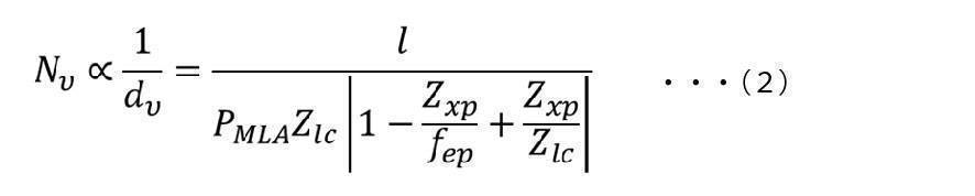
但し、上記(2)式において、dvは隣接する視点のピッチであり、PMLAはマイクロレンズのピッチであり、fepは接眼レンズEPの焦点距離である。
なお、上記(2)式は下記論文からの引用である。
Hekun Huang and Hong Hua 2019,「Generalized methods and strategies for modeling and optimizing the optics of 3D head-mounted light field displays」
Hekun Huang and Hong Hua, 2018,「High-performance integral-imaging-based light field augmented reality display using freeform optics」
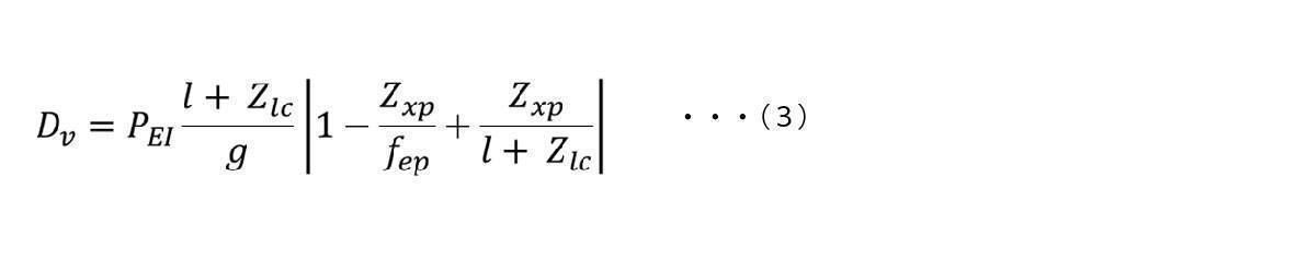
但し、上記(3)式において、PEIは要素画像のピッチを表す。
なお、上記(3)式は下記論文からの引用である。
Hekun Huang and Hong Hua 2019,「Generalized methods and strategies for modeling and optimizing the optics of 3D head-mounted light field displays」
単一のライトフィールド再生装置を用いてインテグラルイメージングによりライトフィールドを再生して複数の視点を生成する例について図10を参照して説明する。
但し、この例では、単一のライトフィールド再生装置を用いて視点群を生成するため、視点数を増やして高い奥行再現性を得るためには、該ライトフィールド再生装置により生成される3次元画像(ライトフィールド)の解像度を下げざるを得ない。
2つのライトフィールド再生装置(第1及び第2ライトフィールド再生装置)を用いてインテグラルイメージングによりライトフィールドを再生して複数の視点を生成する例について図11を参照して説明する。
図12Aに示すライトフィールド再生装置LFPDでは、要素画像表示装置EIDDから射出されマイクロレンズアレイMLAを介した光線群RGの各光線は、接眼レンズEPを介して眼E近傍の対応する視点に集光される。この際、アイトラッキング装置ETDにより眼球Eの向きが検出され、その検出結果に応じて要素画像表示装置EIDDにより表示される要素画像の表示が制御される。これにより、視点数を減らすことなく、ライトフィールド再生装置LFPDにより生成される3次元画像の解像度を上げることができる。
アイトラッキング装置を用いない場合には、図13A、13Bに示すように、眼Eの向きによらずアイボックスEB内に眼Eの瞳が位置するようにアイボックスEBを大きくする必要がある。
アイトラッキング装置を用いる場合には、図14Aに示すように、眼Eが回転して瞳がアイボックスEBから外れそうになったときでも、図14Bに示すように、アイトラッキング装置により検出した眼Eの向きに応じた位置にアイボックスEBを生成することによりアイボックスEB内に眼Eの瞳を位置させることができる。
図15に示す、アイトラッキングを行う場合の眼Eの移動量ΔYに対する要素画像のシフト量Δyは、下記(4)式により求めることができる。

但し、上記(4)式において、fepは、接眼レンズEPの焦点距離である。
以下、本技術の一実施形態の実施例1~14の表示装置について説明する。
[表示装置の構成]
図16は、実施例1の表示装置101の基本的な構成を示す概要図である。表示装置101は、図16に示すように、左眼用の表示装置101-Lと右眼用の表示装置101-Rとから構成される。表示装置1において、一例として、表示装置101-L、101-Rは左右対称にレイアウトされる。表示装置101は、一例として、ユーザの頭部に装着される頭部装着型の表示装置(HMD)である。表示装置101は、例えばユーザにVRを提供するのに用いられる。
詳述すると、表示装置101-Lは、ユーザの左眼50-Lに対応する第1及び第2の3次元画像表示装置10-L、11-Lを有する。表示装置101-Rは、ユーザの右眼50-Rに対応する第1及び第2の3次元画像表示装置10-R、11-Rを有する。
表示装置101Lの第1の3次元画像表示装置10-Lは、要素画像表示装置10-1-Lと、マイクロレンズアレイ10-3-Lとを含む。
表示装置101-Lの視点群生成系は、第1及び第2の3次元画像表示装置10-L、11-Lの各々からの光線群を導光する第1光学系を含む。
表示装置101Lにおいて、第1の3次元画像表示装置10-Lから放射された第1光線群が、光学素子30-Lと、接眼光学素子40-Lと、をこの順で介して、ユーザの左眼50-Lに入射する。このとき、第1光線群は左眼50-Lの瞳面上に、複数の視点S10-Lを含む第1視点群を生成する。
ところで、一般的に3次元画像表示装置では、眼の瞳面上での視点密度を高くすることで、ライトフィールドで再生する3次元空間の奥行方向の再現性を高くすることができる。しかし、視点密度と3次元空間の縦横方向の解像度はトレードオフの関係にあり、視点密度が高くなるほど解像度が低くなる。
[表示装置の構成]
図17は、実施例2の表示装置102の基本的な構成を示す概要図である。表示装置102は、左眼用の表示装置102-Lと右眼用の表示装置102-Rとから構成される。表示装置102において、表示装置102-Lと表示装置102-Rは、左右対称にレイアウトされる。表示装置102は、一例として、ユーザの頭部に装着される頭部装着型の表示装置(HMD)である。表示装置102は、例えばユーザにVRを提供するのに用いられる。
表示装置102-Lにおいて、第1の3次元画像表示装置10-Lから放射された第1光線群が、第1リレー光学系20-Lと、光学素子30-Lと、接眼光学素子40-Lと、をこの順で介して、ユーザの左眼50-Lに入射する。このとき、第1光線群は左眼50-Lの瞳面上に、複数の視点S10-Lを含む第1視点群を生成する。
実施例2の表示装置102によれば、実施例1の表示装置101と同様の効果を得ることができ、且つ、各3次元画像表示装置と対応する光学素子との間にリレーレンズを設けることにより、光学系が大型化する可能性もあるが、接眼レンズだけでは補正できない各種収差を補正することが可能となり、高品質な3次元画像をユーザに提供することができる。また、リレーレンズを設けることにより光路を長くすることができ、該光路上に各種フィルタなどを設置することも容易となる。
[表示装置の構成]
図18は、実施例3の表示装置103の基本的な構成を示す概要図である。表示装置103は、左眼用の表示装置103-Lと右眼用の表示装置103-Rとから構成される。表示装置103において、表示装置103-Lと表示装置103-Rは、左右対称にレイアウトされる。表示装置103は、一例として、ユーザの頭部に装着される頭部装着型の表示装置(HMD)である。表示装置103は、例えばユーザにVRを提供するのに用いられる。
実施例3の表示装置103によれば、実施例2の表示装置102と同様の効果を得ることができるとともに、両眼の各々に対応する表示装置が、第1及び第2の3次元画像表示装置の組を複数組(例えば2組)有しているので、より高密度な視点数とより高い解像度を得ることができる。
[表示装置の構成]
図19は、実施例4の表示装置104の基本的な構成を示す概要図である。表示装置104は、図19に示すように、左眼用の表示装置104-Lと右眼用の表示装置104-Rとから構成される。表示装置104において、表示装置104-L及び表示装置104-Rは、左右対称にレイアウトされる。表示装置104は、一例として、ユーザの頭部に装着される頭部装着型の表示装置(HMD)である。表示装置104は、例えばユーザにVRを提供するのに用いられる。
表示装置104-Lにおいて、第1の3次元画像表示装置13-Lから放射された第1光線群が、第1リレー光学系23-Lと、第1光学素子32-Lと、リレー光学系25-Lと、自由曲面プリズム41-Lと、をこの順で介して、ユーザの左眼50-Lに入射する。このとき、第1光線群は左眼50-Lの瞳面上に、複数の視点S13-Lを含む第1視点群を生成する。
実施例4の表示装置104は、前述したVACを改善するためのHMDの従来技術に比べ、シンプルな構成で、広視野・高解像度を達成し、かつ、レンダリングコストや伝送コストを抑制することが可能である。人間の眼は視野の中心領域の視力が最も高く、それ以外の領域では低い。したがって、人間は視野周辺領域における画質劣化には鈍感である。
[表示装置の構成]
図20は、実施例5の表示装置105の基本的な構成を示す概要図である。表示装置105は、図20に示すように、左眼用の表示装置105-Lと右眼用の表示装置105-Rとから構成される。表示装置105において、表示装置105-L及び表示装置105-Rは、左右対称にレイアウトされる。表示装置105は、一例として、ユーザの頭部に装着される頭部装着型の表示装置(HMD)である。表示装置105は、例えばユーザにARを提供するのに用いられる。
表示装置105-Lにおいて、第1の3次元画像表示装置13-Lから放射された第1光線群が、第1リレー光学系23-Lと、第1光学素子32-Lと、リレー光学系25-Lと、自由曲面プリズム41-Lと、をこの順で介して、ユーザの左眼50-Lに入射する。このとき、第1光線群は、左眼50-Lの瞳面上に、複数の視点S13-Lを含む第1視点群を生成する。
表示装置105によれば、実施例1の表示装置101と同様の効果を得ることができるとともに、各眼に対応する第1及び第2の3次元画像表示装置により生成された、奥行情報を有し焦点調節が誘発される立体画像(立体映像)を、該眼の視野の中心などの限られた範囲に表示し、実世界からの光線と重畳することで、VACの改善されたシースルー性能を有した3D拡張現実ディスプレイを提供することができる。
図21は、実施例6の表示装置106の基本的な構成を示す概要図である。表示装置106は、図21に示すように、左眼用の表示装置106-Lと右眼用の表示装置とから構成される。表示装置106において、表示装置106-L及び該右眼用の表示装置は、左右対称にレイアウトされるため、主として表示装置106-Lについて説明する。表示装置106は、一例として、ユーザの頭部に装着される頭部装着型の表示装置(HMD)である。表示装置106は、例えばユーザにVRを提供するのに用いられる。
表示装置106-Lの視点群生成系は、ユーザの左眼50-Lに対応する3次元画像表示装置10-Lと、接眼光学素子40-L(例えば接眼レンズ)を含む光学系とを有し、3次元画像表示装置10-Lから射出され該光学系を介した光線群により左眼50-Lに対して視点群を生成する。このとき、視点群を構成する複数の視点のうち少なくとも2つの視点が左眼50-Lに生成されることが好ましい。
アイトラッキング装置70-Lは、左眼50-Lの向き(視線)を検出するカメラ70-1-L(受光部)と、照明用の光源70-2-L(光源部)と、を有する。
ここで、図26A及び図26Bに示す比較例の画像表示装置108-Lは、3次元画像表示装置10-Lと、接眼光学素子40-L(例えば接眼レンズ)と、を備える。アイトラッキング装置を用いない場合、眼球回旋やHMDの掛けズレ等を考慮してアイボックスの範囲を広く取る必要がある。図26Aでは、ユーザの左眼51-Lが正面を向いており、アイボックスの範囲E220-Lの中に瞳があるため、ユーザはライトフィールドを正常に視認することができる。図26Bでは、ユーザの左眼51-Lは回旋し、左を向いているが、アイボックスの範囲E220-Lを広く取っているため、瞳がアイボックスの範囲内にあり、ユーザはライトフィールドを正常に視認することができる。しかし、この比較例では、アイボックスサイズが大きいため、視点密度を維持しながらライトフィールドの解像度を向上させることはできない。
図28は、実施例7の表示装置113の基本的な構成を説明する概要図である。表示装置113は、図28に示すように、左眼用の表示装置113-Lと右眼用の表示装置とから構成される。表示装置113において、表示装置113-L及び該右眼用の表示装置は、左右対称にレイアウトされるため、主として表示装置113-Lについて説明する。表示装置113は、一例として、ユーザの頭部に装着される頭部装着型の表示装置(HMD)である。表示装置113は、例えばユーザにVRを提供するのに用いられる。
図29は、実施例8の表示装置114の基本的な構成を示す概要図である。表示装置114は、左眼用の表示装置114-Lと右眼用の表示装置とから構成される。表示装置114において、表示装置114-L及び該右眼用の表示装置は、左右対称にレイアウトされるため、主として表示装置114-Lについて説明する。表示装置114は、一例として、ユーザの頭部に装着される頭部装着型の表示装置(HMD)である。表示装置114は、例えばユーザにVRを提供するのに用いられる。
図30は、実施例9の表示装置115の基本的な構成を示す概要図である。表示装置115は、左眼用の表示装置115-Lと右眼用の表示装置とから構成される。表示装置115において、表示装置115-L及び該右眼用の表示装置は、左右対称にレイアウトされるため、主として表示装置115-Lについて説明する。表示装置115は、一例として、ユーザの頭部に装着される頭部装着型の表示装置(HMD)である。表示装置115は、例えばユーザにVRを提供するのに用いられる。
図31は、実施例10の表示装置116の基本的な構成を示す概要図である。表示装置116は、左眼用の表示装置116-Lと右眼用の表示装置とから構成される。表示装置116において、表示装置116-L及び該右眼用の表示装置は、左右対称にレイアウトされるため、主として表示装置116-Lについて説明する。表示装置116は、一例として、ユーザの頭部に装着される頭部装着型の表示装置(HMD)である。表示装置116は、例えばユーザにARを提供するのに用いられる。
図32は、実施例11の表示装置117の基本的な構成を示す概要図である。表示装置117は、左眼用の表示装置117-Lと右眼用の表示装置とから構成される。表示装置117において、表示装置117-L及び該右眼用の表示装置は、左右対称にレイアウトされるため、主として表示装置117-Lについて説明する。表示装置117は、一例として、ユーザの頭部に装着される頭部装着型の表示装置(HMD)である。表示装置117は、例えばユーザにVRを提供するのに用いられる。
当該透過型空間変調器として、例えば液晶素子(LCD)が用いられる。
当該表示素子として、例えばmicro LEDアレイ、OLEDアレイ等が用いられる。
図33は、実施例12の表示装置118の基本的な構成を示す概要図である。表示装置118は、左眼用の表示装置118-Lと右眼用の表示装置とから構成される。表示装置118において、表示装置118-L及び該右眼用の表示装置は、左右対称にレイアウトされるため、主として表示装置118-Lについて説明する。表示装置118は、一例として、ユーザの頭部に装着される頭部装着型の表示装置(HMD)である。表示装置118は、例えばユーザにVRを提供するのに用いられる。
図34は、実施例13の表示装置119の基本的な構成を示す概要図である。表示装置119は、左眼用の表示装置119-Lと右眼用の表示装置とから構成される。表示装置119において、表示装置119-L及び該右眼用の表示装置は、左右対称にレイアウトされるため、主として表示装置119-Lについて説明する。表示装置119は、一例として、ユーザの頭部に装着される頭部装着型の表示装置(HMD)である。表示装置119は、例えばユーザにVRを提供するのに用いられる。
図35は、実施例14の表示装置120の基本的な構成を示す概要図である。表示装置120は、図35に示すように、左眼用の表示装置120-Lと右眼用の表示装置とから構成される。表示装置120において、表示装置120-L及び該右眼用の表示装置は、左右対称にレイアウトされるため、主として表示装置120-Lについて説明する。表示装置120は、一例として、ユーザの頭部に装着される頭部装着型の表示装置(HMD)である。表示装置120は、例えばユーザにVRを提供するのに用いられる。
Lから射出された光のうち所定の偏光方向の第1直線偏光が光学素子16-3-Lを透過し、1/4波長板16-4-Lに入射される。1/4波長板16-4-Lに入射された第1直線偏光は、円偏光に変換され、反射型空間変調器16-5-Lに入射される。反射型空間変調器16-5-Lで反射されつつ生成された光線群は、円偏光の回転方向が逆向きとなり、1/4波長板16-4-Lで偏光方向が第1直線偏光と直交する第2直線偏光に変換され、光学素子16-3-Lに入射される。光学素子16-3-Lに入射された光線群は、光学素子16-3-Lでレンズ16-6-Lに向けて反射される。レンズ16-6-Lを介した光線群は、1/4波長板16-7-Lで円偏光に変換され、ミラー16-8-Lに入射される。ミラー16-8-Lで反射された光線群は、円偏光の回転方向が逆向きになり、1/4波長板16-7-Lで第1直線偏光に変換され、レンズ16-6-L、光学素子16-3-Lをこの順に透過し、透過型空間変調器16-9-Lに入射される。透過型空間変調器16-9-Lを介した光線群の各光線は、アパーチャアレイ16-10-L、マイクロレンズアレイ16-11-L及び接眼光学素子40-Lをこの順に介して、対応する視点に集光され、視点群が生成される。
以上説明した本技術の各実施例及び各変形例の表示装置の構成は、適宜変更可能である。
(1)ユーザの両眼の各々に対応する複数の3次元画像表示装置を有し、前記複数の3次元画像表示装置の各々から射出された光線群により前記両眼の対応する眼に対して視点群を生成する視点群生成系を備える、表示装置。
(2)複数の前記視点群は、重ならない、(1)に記載の表示装置。
(3)複数の前記視点群を構成する複数の視点のうち少なくとも2つの視点が前記眼に生成される、(1)又は(2)に記載の表示装置。
(4)複数の前記視点群のうち少なくとも一の視点群の隣り合う2つの視点間に他の視点群の視点が生成される、(1)~(3)のいずれか1つに記載の表示装置。
(5)前記複数の3次元画像表示装置の各々は、要素画像表示装置と、マイクロレンズアレイと、を含む、(1)~(4)のいずれか1つに記載の表示装置。
(6)前記複数の3次元画像表示装置の各々は、前記要素画像表示装置と前記マイクロレンズアレイとの間に配置されたアパーチャアレイを更に含む、(5)に記載の表示装置。
(7)前記複数の3次元画像表示装置は、前記光線群の射出方向が交差する第1及び第2の3次元画像表示装置の組を少なくとも1組有し、前記視点群生成系は、前記複数の3次元画像表示装置の各々からの前記光線群を導光する光学系を含む、(1)~(6)のいずれか1つに記載の表示装置。
(8)前記光学系は、前記第1の3次元画像表示装置からの前記光線群である第1光線群及び前記第2の3次元画像表示装置からの前記光線群である第2光線群の進行方向を揃える第1光学素子を有する、(7)に記載の表示装置。
(9)前記光学系は、前記第1の3次元画像表示装置と、前記第1光学素子との間に配置され、前記第1光線群の中間像を生成する第1リレー光学系と、前記第2の3次元画像表示装置と、前記第1光学素子との間に配置され、前記第2光線群の中間像を生成する第2リレー光学系と、の少なくとも一方を更に有する、(8)に記載の表示装置。
(10)前記複数の3次元画像表示装置は、前記第1及び第2の3次元画像表示装置の組を1組有し、前記第1光学素子は、第1及び第2光線群の進行方向を前記眼に向かう方向に揃える、(8)又は(9)に記載の表示装置。
(11)前記第1光学素子は、ビームスプリッタである、(8)~(10)のいずれか1つに記載の表示装置。
(12)前記光学系は、前記第1光学素子からの前記第1及び第2光線群が入射される接眼光学素子を更に有する、(8)~(11)のいずれか1つに記載の表示装置。
(13)前記第1光学素子は、接眼光学素子としても機能する自由曲面プリズムである、(8)~(10)のいずれか1つに記載の表示装置。
(14)前記複数の3次元画像表示装置は、前記第1及び第2の3次元画像表示装置の組を複数組有し、前記第1光学素子は、前記複数組の各組毎に設けられ、前記複数の第1光学素子のうち一の第1光学素子からの前記第1及び第2光線群を含む一の光線群対の進行方向と、他の第1光学素子からの前記第1及び第2光線群を含む他の光線群対の進行方向とが交差し、前記光学系は、前記一及び他の光線群対の進行方向を揃える第2光学素子を更に有する、(8)又は(9)に記載の表示装置。
(15)前記第1及び第2光学素子の少なくとも一方は、ビームスプリッタである、(14)に記載の表示装置。
(16)前記光学系は、前記第2光学素子からの前記一及び他の光線群対が入射される接眼光学素子を更に有する、(14)又は(15)に記載の表示装置。
(17)前記第2光学素子は、接眼光学素子としても機能する自由曲面プリズムである、(14)又は(15)に記載の表示装置。
(18)前記光学系は、前記一の第1光学素子と前記第2光学素子との間に配置され、前記一の第1光学素子からの前記第1及び第2光線群の中間像を生成する第1リレー光学系と、前記他の第1光学素子と前記第2光学素子との間に配置され、前記他の第1光学素子からの前記第1及び第2光線群の中間像を生成する第2リレー光学系と、の少なくとも一方を更に有する、(14)~(17)のいずれか1つに記載の表示装置。
(19)前記複数の3次元画像表示装置は、第3の3次元画像表示装置を更に有し、前記第1光学素子からの前記第1及び第2光線群を含む光線群対の進行方向と、前記第3の3次元画像表示装置からの光線群である第3光線群の進行方向とが交差し、前記光学系は、前記光線群対及び前記第3光線群の進行方向を揃える第2光学素子を更に有する、(8)~(18)のいずれか1つに記載の表示装置。
(20)前記第1及び第2光学素子の少なくとも一方は、ビームスプリッタである、(19)に記載の表示装置。
(21)前記ユーザの両眼の各々に対応する2次元画像表示装置を更に備え、前記2次元画像表示装置から射出された光線群の進行方向と、前記第1光学素子からの前記第1及び第2光線群を含む光線群対の進行方向とが交差し、前記光学系は、前記光線群及び前記光線群対の進行方向を揃える第2光学素子を更に有する、(8)~(20)に記載の表示装置。
(22)前記光学系は、前記第1及び第2光学素子の間に配置され、前記第1光学素子からの前記第1及び第2光線群の中間像を生成するリレー光学系を更に有する、(21)に記載の表示装置。
(23)前記第2光学素子は、接眼光学素子としても機能する自由曲面プリズムである、(21)又は(22)に記載の表示装置。
(24)前記複数の3次元画像表示装置の各々の前記要素画像表示装置は、ディスプレイを含む、(5)~(23)のいずれか1つに記載の表示装置。
(25)複数の前記ディスプレイは、積層されている、(24)に記載の表示装置。
(26)前記複数の3次元画像表示装置は、前記マイクロレンズアレイを共有する、(24)又は(25)に記載の表示装置。
(27)前記視点群生成系は、前記複数のディスプレイの各々からの光線群が入射される接眼光学素子を含む、(24)~(26)のいずれか1つに記載の表示装置。
(28)複数の前記ディスプレイの少なくとも1つは、光源及び空間変調器を含む、(24)~(27)のいずれか1つに記載の表示装置。
(29)前記複数のディスプレイは、反射型空間変調器を有する第1ディスプレイと、透過型空間変調器を有する第2ディスプレイとを含み、前記反射型空間変調器及び前記透過型空間変調器は、光線群の射出方向が交差し、前記光学系は、前記反射型空間変調器からの前記光線群の進行方向を前記透過型空間変調器からの前記光線群の進行方向に揃える光学素子を有する、(28)に記載の表示装置。
(30)前記空間変調器は、液晶素子である、(28)又は(29)に記載の表示装置。
(31)前記空間変調器は、透過型である、(28)又は(30)に記載の表示装置。
(32)前記空間変調器は、反射型である、(28)又は(30)に記載の表示装置。
(33)前記空間変調器は、FLCOS(Ferroelectric Liquid Crystal on Silicon)である、(32)に記載の表示装置。
(34)前記空間変調器は、DMD(Digital Mirror Device)である、(32)に記載の表示装置。
(35)複数の前記ディスプレイの少なくとも1つは、自発光型の表示素子を含む、(24)~(27)のいずれか1つに記載の表示装置。
(36)前記表示素子は、LED(Light Emitting Diode)、又はOLED(Organic Light Emitting Diode)を有する、(35)に記載の表示装置。
(37)前記ユーザの視線を検出する視線検出系を更に備え、前記視点群生成系は、前記視線検出系の検出結果に基づいて前記視点群の生成位置を制御する、(1)~(36)のいずれか1つに記載の表示装置。
(38)頭部装着型である、(1)~(37)のいずれか1つに記載の表示装置。
(39)ユーザの両眼の各々に対応する3次元画像表示装置と接眼光学素子を含む光学系とを有し、前記3次元画像表示装置から射出され前記光学系を介した光線群により前記両眼の対応する眼に対して視点群を生成する視点群生成系と、
前記ユーザの視線を検出する視線検出系と、
を備え、
前記視点群生成系は、前記視線検出系の検出結果に基づいて前記視点群の生成位置を制御する、表示装置。
(40)前記複数の3次元画像表示装置の各々は、要素画像表示装置と、マイクロレンズアレイと、を含む、(39)に記載の表示装置。
(41)前記複数の3次元画像表示装置の各々は、前記要素画像表示装置と前記マイクロレンズアレイとの間に配置されたアパーチャアレイを更に含む、(40)に記載の表示装置。
(42)前記視線検出系は、非可視光を射出する光源部と、前記光源部から射出され前記両眼の一方の眼で反射された前記非可視光を受光する受光部と、を含む、(39)~(41)のいずれか1つに記載の表示装置。
(43)前記視線検出系は、前記両眼の一方の眼に対応する前記接眼光学素子に設けられている、(39)~(42)のいずれか1つに記載の表示装置。
(44)前記視線検出系は、前記両眼の一方の眼に対応する前記3次元画像表示装置に設けられている、(39)~(42)のいずれか1つに記載の表示装置。
(45)前記一方の眼に対応する前記3次元画像表示装置からの前記光線群の射出方向と、前記光源部からの前記非可視光の射出方向とが交差し、前記光学系は、前記光線群及び前記非可視光の進行方向を揃える光学素子を更に有する、(42)に記載の表示装置。
(46)前記光源部から射出された前記非可視光は、前記光学素子及び前記接眼光学素子をこの順に介して前記一方の眼に照射され、前記受光部は、前記一方の眼で反射された前記非可視光を前記接眼光学素子及び前記光学素子をこの順に介して受光する、(45)に記載の表示装置。
(47)前記光学素子は、ビームスプリッタである、(45)又は(46)に記載の表示装置。
(48)前記一方の眼に対応する前記3次元画像表示装置からの前記光線群の射出方向と、前記光源部からの前記非可視光の射出方向とが交差し、前記接眼光学素子は、前記光線群及び前記非可視光の進行方向を揃える自由曲面プリズムである、(42)に記載の表示装置。
(49)前記光源部から射出された前記非可視光は、前記接眼光学素子を介して前記一方の眼に照射され、前記受光部は、前記一方の眼で反射された前記非可視光を前記接眼光学素子を介して受光する、(48)に記載の表示装置。
(50)頭部装着型である、(39)~(49)のいずれか1つに記載の表示装置。
(51)ユーザの両眼の各々に対応する複数の3次元画像表示装置の各々から射出された光線群により前記両眼の対応する眼に対して視点群を生成する、表示方法。
(52)ユーザの視線を検出する工程と、
前記ユーザの両眼の各々に対応する3次元画像表示装置から射出され接眼光学素子を含む光学系を介した光線群により前記両眼の対応する眼に対して視点群を生成する工程と、
を含み、
前記視点群を生成する工程では、前記検出する工程での検出結果に基づいて前記視点群の生成位置を制御する、表示方法。
-3-R、13-3-L、13-3-R、14-3-L、15-3-L、1-11-L:マイクロレンズアレイ、14-1-L、15-1-L:ディスプレイ、16-5-L:反射型空間変調器、16-9-L:透過型空間変調器、20-L、20-R、23-L、23-R:第1リレー光学系、21-L、21-R、22-L、22-R:第2リレー光学系、24-L、24-R:リレー光学系(第1リレー光学系)、25-L、25-R:リレー光学系(第2リレー光学系)、30-L、30-R:光学素子(第1光学素子)、31-L、31-R、32-L、32-R:第1光学素子、30-L、30-R:第2光学素子、40-L、40-R:接眼光学素子、41-L、41-R:自由曲面プリズム、60-L、60-R:2次元画像表示装置、70-L:アイトラッキング装置(視線検出系の少なくとも一部)、70-1-L:光源(光源部)、70-2-L:カメラ(受光部)、S10-L、S10-R、S11-L、S11-R、S12-L、S12-R、S13-L、S13-R:視点(視点群の一部)。
Claims (52)
- ユーザの両眼の各々に対応する複数の3次元画像表示装置を有し、前記複数の3次元画像表示装置の各々から射出された光線群により前記両眼の対応する眼に対して視点群を生成する視点群生成系を備える、表示装置。
- 複数の前記視点群は、重ならない、請求項1に記載の表示装置。
- 複数の前記視点群を構成する複数の視点のうち少なくとも2つの視点が前記眼に生成される、請求項1に記載の表示装置。
- 複数の前記視点群のうち少なくとも一の視点群の隣り合う2つの視点間に他の視点群の視点が生成される、請求項1に記載の表示装置。
- 前記複数の3次元画像表示装置の各々は、
要素画像表示装置と、
マイクロレンズアレイと、
を含む、請求項1に記載の表示装置。 - 前記複数の3次元画像表示装置の各々は、前記要素画像表示装置と前記マイクロレンズアレイとの間に配置されたアパーチャアレイを更に含む、請求項5に記載の表示装置。
- 前記複数の3次元画像表示装置は、前記光線群の射出方向が交差する第1及び第2の3次元画像表示装置の組を少なくとも1組有し、
前記視点群生成系は、前記複数の3次元画像表示装置の各々からの前記光線群を導光する光学系を含む、請求項1に記載の表示装置。 - 前記光学系は、前記第1の3次元画像表示装置からの前記光線群である第1光線群及び前記第2の3次元画像表示装置からの前記光線群である第2光線群の進行方向を揃える第1光学素子を有する、請求項7に記載の表示装置。
- 前記光学系は、
前記第1の3次元画像表示装置と、前記第1光学素子との間に配置され、前記第1光線群の中間像を生成する第1リレー光学系と、
前記第2の3次元画像表示装置と、前記第1光学素子との間に配置され、前記第2光線群の中間像を生成する第2リレー光学系と、
の少なくとも一方を更に有する、請求項8に記載の表示装置。 - 前記複数の3次元画像表示装置は、前記第1及び第2の3次元画像表示装置の組を1組有し、
前記第1光学素子は、第1及び第2光線群の進行方向を前記眼に向かう方向に揃える、請求項8に記載の表示装置。 - 前記第1光学素子は、ビームスプリッタである、請求項10に記載の表示装置。
- 前記光学系は、前記第1光学素子からの前記第1及び第2光線群が入射される接眼光学素子を更に有する、請求項11に記載の表示装置。
- 前記第1光学素子は、接眼光学素子としても機能する自由曲面プリズムである、請求項10に記載の表示装置。
- 前記複数の3次元画像表示装置は、前記第1及び第2の3次元画像表示装置の組を複数組有し、
前記第1光学素子は、前記複数組の各組毎に設けられ、
前記複数の第1光学素子のうち一の第1光学素子からの前記第1及び第2光線群を含む一の光線群対の進行方向と、他の第1光学素子からの前記第1及び第2光線群を含む他の光線群対の進行方向とが交差し、
前記光学系は、前記一及び他の光線群対の進行方向を揃える第2光学素子を更に有する、請求項8に記載の表示装置。 - 前記第1及び第2光学素子の少なくとも一方は、ビームスプリッタである、請求項14に記載の表示装置。
- 前記光学系は、前記第2光学素子からの前記一及び他の光線群対が入射される接眼光学素子を更に有する、請求項14に記載の表示装置。
- 前記第2光学素子は、接眼光学素子としても機能する自由曲面プリズムである、請求項14に記載の表示装置。
- 前記光学系は、
前記一の第1光学素子と前記第2光学素子との間に配置され、前記一の第1光学素子からの前記第1及び第2光線群の中間像を生成する第1リレー光学系と、
前記他の第1光学素子と前記第2光学素子との間に配置され、前記他の第1光学素子からの前記第1及び第2光線群の中間像を生成する第2リレー光学系と、
の少なくとも一方を更に有する、請求項14に記載の表示装置。 - 前記複数の3次元画像表示装置は、第3の3次元画像表示装置を更に有し、
前記第1光学素子からの前記第1及び第2光線群を含む光線群対の進行方向と、前記第3の3次元画像表示装置からの光線群である第3光線群の進行方向とが交差し、
前記光学系は、前記光線群対及び前記第3光線群の進行方向を揃える第2光学素子を更に有する、請求項8に記載の表示装置。 - 前記第1及び第2光学素子の少なくとも一方は、ビームスプリッタである、請求項19に記載の表示装置。
- 前記ユーザの両眼の各々に対応する2次元画像表示装置を更に備え、
前記2次元画像表示装置から射出された光線群の進行方向と、前記第1光学素子からの前記第1及び第2光線群を含む光線群対の進行方向とが交差し、
前記光学系は、前記光線群及び前記光線群対の進行方向を揃える第2光学素子を更に有する、請求項8に記載の表示装置。 - 前記光学系は、前記第1及び第2光学素子の間に配置され、前記第1光学素子からの前記第1及び第2光線群の中間像を生成するリレー光学系を更に有する、請求項21に記載の表示装置。
- 前記第2光学素子は、接眼光学素子としても機能する自由曲面プリズムである、請求項21に記載の表示装置。
- 前記複数の3次元画像表示装置の各々の前記要素画像表示装置は、ディスプレイを含む、請求項5に記載の表示装置。
- 複数の前記ディスプレイは、積層されている、請求項24に記載の表示装置。
- 前記複数の3次元画像表示装置は、前記マイクロレンズアレイを共有する、請求項24に記載の表示装置。
- 前記視点群生成系は、複数の前記ディスプレイの各々からの光線群が入射される接眼光学素子を含む、請求項24に記載の表示装置。
- 複数の前記ディスプレイの少なくとも1つは、光源及び空間変調器を含む、請求項24に記載の表示装置。
- 前記複数のディスプレイは、反射型空間変調器を有する第1ディスプレイと、透過型空間変調器を有する第2ディスプレイとを含み、
前記反射型空間変調器及び前記透過型空間変調器は、光線群の射出方向が交差し、
前記光学系は、前記反射型空間変調器からの前記光線群の進行方向を前記透過型空間変調器からの前記光線群の進行方向に揃える光学素子を有する、請求項28に記載の表示装置。 - 前記空間変調器は、液晶素子である、請求項28に記載の表示装置。
- 前記空間変調器は、透過型である、請求項28に記載の表示装置。
- 前記空間変調器は、反射型である、請求項28に記載の表示装置。
- 前記空間変調器は、FLCOS(Ferroelectric Liquid Crystal on Silicon)である、請求項32に記載の表示装置。
- 前記空間変調器は、DMD(Digital Mirror Device)である、請求項32に記載の表示装置。
- 複数の前記ディスプレイの少なくとも1つは、自発光型の表示素子を含む、請求項24に記載の表示装置。
- 前記表示素子は、LED(Light Emitting Diode)、又はOLED(Organic Light Emitting Diode)を有する、請求項35に記載の表示装置。
- 前記ユーザの視線を検出する視線検出系を更に備え、
前記視点群生成系は、前記視線検出系の検出結果に基づいて前記視点群の生成位置を制御する、請求項1に記載の表示装置。 - 頭部装着型である、請求項1に記載の表示装置。
- ユーザの両眼の各々に対応する3次元画像表示装置と接眼光学素子を含む光学系とを有し、前記3次元画像表示装置から射出され前記光学系を介した光線群により前記両眼の対応する眼に対して視点群を生成する視点群生成系と、
前記ユーザの視線を検出する視線検出系と、
を備え、
前記視点群生成系は、前記視線検出系の検出結果に基づいて前記視点群の生成位置を制御する、表示装置。 - 前記複数の3次元画像表示装置の各々は、
要素画像表示装置と、
マイクロレンズアレイと、
を含む、請求項39に記載の表示装置。 - 前記複数の3次元画像表示装置の各々は、前記要素画像表示装置と前記マイクロレンズアレイとの間に配置されたアパーチャアレイを更に含む、請求項40に記載の表示装置。
- 前記視線検出系は、
非可視光を射出する光源部と、
前記光源部から射出され前記両眼の一方の眼で反射された前記非可視光を受光する受光部と、
を含む、請求項39に記載の表示装置。 - 前記視線検出系は、前記一方の眼に対応する前記接眼光学素子に設けられている、請求項39に記載の表示装置。
- 前記視線検出系は、前記一方の眼に対応する前記3次元画像表示装置に設けられている、請求項39に記載の表示装置。
- 前記一方の眼に対応する前記3次元画像表示装置からの前記光線群の射出方向と、前記光源部からの前記非可視光の射出方向とが交差し、
前記光学系は、前記光線群及び前記非可視光の進行方向を揃える光学素子を更に有する、請求項42に記載の表示装置。 - 前記光源部から射出された前記非可視光は、前記光学素子及び前記接眼光学素子をこの順に介して前記一方の眼に照射され、
前記受光部は、前記一方の眼で反射された前記非可視光を前記接眼光学素子及び前記光学素子をこの順に介して受光する、請求項45に記載の表示装置。 - 前記光学素子は、ビームスプリッタである、請求項45に記載の表示装置。
- 前記一方の眼に対応する前記3次元画像表示装置からの前記光線群の射出方向と、前記光源部からの前記非可視光の射出方向とが交差し、
前記接眼光学素子は、前記光線群及び前記非可視光の進行方向を揃える自由曲面プリズムである、請求項42に記載の表示装置。 - 前記光源部から射出された前記非可視光は、前記接眼光学素子を介して前記一方の眼に照射され、
前記受光部は、前記一方の眼で反射された前記非可視光を前記接眼光学素子を介して受光する、請求項48に記載の表示装置。 - 頭部装着型である、請求項39に記載の表示装置。
- ユーザの両眼の各々に対応する複数の3次元画像表示装置の各々から射出された光線群により前記両眼の対応する眼に対して視点群を生成する、表示方法。
- ユーザの視線を検出する工程と、
前記ユーザの両眼の各々に対応する3次元画像表示装置から射出され接眼光学素子を含む光学系を介した光線群により前記両眼の対応する眼に対して視点群を生成する工程と、
を含み、
前記視点群を生成する工程では、前記検出する工程での検出結果に基づいて前記視点群の生成位置を制御する、表示方法。
Priority Applications (3)
| Application Number | Priority Date | Filing Date | Title |
|---|---|---|---|
| EP22858057.7A EP4382995A4 (en) | 2021-08-20 | 2022-02-18 | DISPLAY APPARATUS AND DISPLAY METHOD |
| CN202280055682.9A CN117795396A (zh) | 2021-08-20 | 2022-02-18 | 显示设备和显示方法 |
| US18/683,292 US12574491B2 (en) | 2021-08-20 | 2022-02-18 | Display apparatus and display method |
Applications Claiming Priority (2)
| Application Number | Priority Date | Filing Date | Title |
|---|---|---|---|
| JP2021-134868 | 2021-08-20 | ||
| JP2021134868 | 2021-08-20 |
Publications (1)
| Publication Number | Publication Date |
|---|---|
| WO2023021732A1 true WO2023021732A1 (ja) | 2023-02-23 |
Family
ID=85240294
Family Applications (1)
| Application Number | Title | Priority Date | Filing Date |
|---|---|---|---|
| PCT/JP2022/006519 Ceased WO2023021732A1 (ja) | 2021-08-20 | 2022-02-18 | 表示装置及び表示方法 |
Country Status (4)
| Country | Link |
|---|---|
| US (1) | US12574491B2 (ja) |
| EP (1) | EP4382995A4 (ja) |
| CN (1) | CN117795396A (ja) |
| WO (1) | WO2023021732A1 (ja) |
Cited By (1)
| Publication number | Priority date | Publication date | Assignee | Title |
|---|---|---|---|---|
| US11927761B1 (en) * | 2020-07-21 | 2024-03-12 | Apple Inc. | Head-mounted display systems |
Families Citing this family (1)
| Publication number | Priority date | Publication date | Assignee | Title |
|---|---|---|---|---|
| CN119882262B (zh) * | 2025-03-27 | 2025-07-11 | 成都工业学院 | 一种基于复合集成光源的大景深显示装置 |
Citations (11)
| Publication number | Priority date | Publication date | Assignee | Title |
|---|---|---|---|---|
| JPH08234141A (ja) * | 1994-12-01 | 1996-09-13 | Olympus Optical Co Ltd | 頭部装着型映像表示装置 |
| JPH08237691A (ja) * | 1994-12-29 | 1996-09-13 | Sharp Corp | 観察者追跡型自動立体表示装置および観察者追跡方法 |
| JPH09322197A (ja) * | 1996-05-24 | 1997-12-12 | Olympus Optical Co Ltd | 立体視ディスプレイ装置 |
| JP2014219621A (ja) * | 2013-05-10 | 2014-11-20 | 株式会社タイトー | 表示装置、表示制御プログラム |
| JP2015521298A (ja) | 2012-04-25 | 2015-07-27 | マイクロソフト コーポレーション | ヘッドマウントディスプレイに用いるための可動式ledアレイ及びマイクロレンズアレイに基づくライトフィールドプロジェクタ |
| JP2017062295A (ja) * | 2015-09-24 | 2017-03-30 | 日本放送協会 | 立体画像表示装置 |
| JP2017515162A (ja) | 2014-03-05 | 2017-06-08 | アリゾナ ボード オブ リージェンツ オン ビハーフ オブ ザ ユニバーシティ オブ アリゾナ | ウェアラブル3d拡張現実ディスプレイ |
| JP2020513595A (ja) | 2016-11-15 | 2020-05-14 | クリアル・スリーディー・ソシエテ・アノニム | 正しい単眼奥行き手がかりを持つニアアイシーケンシャルライトフィールドプロジェクタ |
| JP2020514811A (ja) * | 2017-03-09 | 2020-05-21 | アリゾナ ボード オブ リージェンツ オン ビハーフ オブ ザ ユニバーシティ オブ アリゾナ | インテグラルイメージングおよび導波路プリズムを用いたヘッドマウント・ライトフィールド・ディスプレイ |
| JP2020520475A (ja) | 2017-05-15 | 2020-07-09 | グーグル エルエルシー | アイトラッキングを介した拡張された有効なアイボックスを有するニアアイディスプレイ |
| JP2020521174A (ja) | 2017-05-18 | 2020-07-16 | アリゾナ ボード オブ リージェンツ オン ビハーフ オブ ザ ユニバーシティ オブ アリゾナ | 多層高ダイナミックレンジ・ヘッドマウントディスプレイ |
Family Cites Families (60)
| Publication number | Priority date | Publication date | Assignee | Title |
|---|---|---|---|---|
| JPH0772446A (ja) * | 1993-09-01 | 1995-03-17 | Sharp Corp | 表示システム |
| US5737012A (en) | 1994-12-01 | 1998-04-07 | Olympus Optical Co., Ltd. | Head mounted image display apparatus and image forming apparatus related thereto |
| JPH09322199A (ja) * | 1996-05-29 | 1997-12-12 | Olympus Optical Co Ltd | 立体映像ディスプレイ装置 |
| US6710920B1 (en) * | 1998-03-27 | 2004-03-23 | Sanyo Electric Co., Ltd | Stereoscopic display |
| US7428001B2 (en) * | 2002-03-15 | 2008-09-23 | University Of Washington | Materials and methods for simulating focal shifts in viewers using large depth of focus displays |
| US20060109753A1 (en) * | 2004-11-23 | 2006-05-25 | Fergason James L | Monitor for showing high-resolution and three-dimensional images and method |
| KR101686843B1 (ko) * | 2006-09-29 | 2016-12-15 | 리얼디 인크. | 투사 시스템 및 입체 이미지 투사를 위한 방법 |
| WO2009015375A1 (en) * | 2007-07-26 | 2009-01-29 | Real D | Head-mounted single panel stereoscopic display |
| US8434871B2 (en) * | 2008-01-07 | 2013-05-07 | The Salk Institute For Biological Studies | Projection screens for three dimensional images |
| US20110141250A1 (en) * | 2009-12-15 | 2011-06-16 | Huang-Tzung Jan | Stereo-image display apparatus |
| US8643684B2 (en) * | 2011-01-18 | 2014-02-04 | Disney Enterprises, Inc. | Multi-layer plenoptic displays that combine multiple emissive and light modulating planes |
| US9179134B2 (en) * | 2011-01-18 | 2015-11-03 | Disney Enterprises, Inc. | Multi-layer plenoptic displays that combine multiple emissive and light modulating planes |
| EP2506587A2 (en) * | 2011-03-31 | 2012-10-03 | Fujifilm Corporation | Stereoscopic display apparatus |
| US8692738B2 (en) * | 2011-06-10 | 2014-04-08 | Disney Enterprises, Inc. | Advanced Pepper's ghost projection system with a multiview and multiplanar display |
| TWI457605B (zh) * | 2011-12-16 | 2014-10-21 | Delta Electronics Inc | 立體顯示裝置 |
| JP6056171B2 (ja) * | 2012-03-29 | 2017-01-11 | 富士通株式会社 | 立体画像表示装置及び方法 |
| JP6021541B2 (ja) * | 2012-09-13 | 2016-11-09 | キヤノン株式会社 | 画像処理装置及び方法 |
| TW201427386A (zh) * | 2012-12-18 | 2014-07-01 | Wintek Corp | 可平衡左右眼影像亮度之立體影像系統及相關驅動方法 |
| JP6212877B2 (ja) * | 2013-02-20 | 2017-10-18 | 富士通株式会社 | 画像表示装置及び画像表示方法 |
| US9013564B2 (en) * | 2013-05-07 | 2015-04-21 | Elwha Llc | Controllable lenticular lenslets |
| KR102530558B1 (ko) * | 2016-03-16 | 2023-05-09 | 삼성전자주식회사 | 투시형 디스플레이 장치 |
| US10178948B2 (en) * | 2016-05-11 | 2019-01-15 | Miraco Light Inc. | Self operatable ophthalmic device |
| KR101831748B1 (ko) * | 2016-10-11 | 2018-02-26 | 전자부품연구원 | 무안경 3d 디스플레이 장치 |
| US10373297B2 (en) * | 2016-10-26 | 2019-08-06 | Valve Corporation | Using pupil location to correct optical lens distortion |
| EP3574364B1 (en) * | 2017-01-25 | 2026-04-29 | Samsung Electronics Co., Ltd. | Head-mounted display apparatus, and method thereof for generating 3d image information |
| JP6964250B2 (ja) * | 2017-02-07 | 2021-11-10 | パナソニックIpマネジメント株式会社 | 眼球撮影装置および眼球撮影方法 |
| US11132055B2 (en) * | 2017-12-03 | 2021-09-28 | Esight Corp. | Enhancing the performance of near-to-eye vision systems |
| US20190219818A1 (en) * | 2018-01-17 | 2019-07-18 | Tobii Ab | Eye tracking for augmented reality and virtual reality |
| US11546575B2 (en) | 2018-03-22 | 2023-01-03 | Arizona Board Of Regents On Behalf Of The University Of Arizona | Methods of rendering light field images for integral-imaging-based light field display |
| WO2019192682A1 (en) * | 2018-04-03 | 2019-10-10 | Huawei Technologies Co., Ltd. | Display device for head-mounting and display method |
| CN112313737B (zh) * | 2018-06-22 | 2023-05-26 | 三菱电机株式会社 | 影像显示装置 |
| US11272168B2 (en) * | 2018-07-16 | 2022-03-08 | Boe Technology Group Co., Ltd. | Three-dimensional display apparatus, three-dimensional imaging apparatus, and method of displaying three-dimensional image |
| US10852546B2 (en) * | 2018-08-01 | 2020-12-01 | Htc Corporation | Head mounted display and multiple depth imaging apparatus |
| CN112888987B (zh) * | 2018-09-28 | 2025-08-19 | 光场实验室公司 | 用于光场显示器的全息对象中继 |
| CN111328380B (zh) * | 2018-10-15 | 2023-04-04 | 国立大学法人东京农工大学 | 头戴式显示器以及头戴式显示器中使用的广焦点透镜的设计方法 |
| JP7122244B2 (ja) * | 2018-12-21 | 2022-08-19 | 株式会社日立エルジーデータストレージ | ヘッドマウントディスプレイ |
| EP3929651B1 (en) * | 2019-02-19 | 2024-08-07 | JVCKenwood Corporation | Head-mounted display |
| JP7317578B2 (ja) * | 2019-06-05 | 2023-07-31 | 株式会社小糸製作所 | 画像表示装置 |
| JP7338324B2 (ja) * | 2019-08-28 | 2023-09-05 | 株式会社Jvcケンウッド | ヘッドマウントディスプレイ |
| WO2021045743A1 (en) * | 2019-09-04 | 2021-03-11 | Google Llc | Polarization-dependent augmented reality display |
| KR20220099556A (ko) * | 2019-11-12 | 2022-07-13 | 라이트 필드 랩 인코포레이티드 | 중계 시스템 |
| US20210294119A1 (en) * | 2020-03-17 | 2021-09-23 | Lightspace Technologies, SIA | Display apparatus for rendering three-dimensional image and method therefor |
| US12315120B2 (en) * | 2020-04-27 | 2025-05-27 | Sony Group Corporation | Display apparatus and display method |
| JP7444983B2 (ja) * | 2020-06-17 | 2024-03-06 | 株式会社有沢製作所 | 立体表示装置 |
| WO2021258078A1 (en) * | 2020-06-19 | 2021-12-23 | Hes Ip Holdings, Llc | Image display systems for eyebox expansion and methods of making the same |
| KR102489272B1 (ko) * | 2020-07-07 | 2023-01-17 | 한국과학기술연구원 | 근안 디스플레이 장치 |
| US11906736B1 (en) * | 2020-08-03 | 2024-02-20 | Raytrx, Llc | Wearable pupil-forming display apparatus |
| US11353711B1 (en) * | 2020-08-03 | 2022-06-07 | Raytrx, Llc | Wearable pupil-forming display apparatus |
| KR102807770B1 (ko) * | 2020-09-04 | 2025-05-15 | 삼성디스플레이 주식회사 | 라이트 필드 표시 장치 및 이의 영상 처리 방법 |
| JP2022090779A (ja) * | 2020-12-08 | 2022-06-20 | ソニーグループ株式会社 | 画像表示装置及び表示装置 |
| WO2022196809A1 (ja) * | 2021-03-19 | 2022-09-22 | 株式会社Jvcケンウッド | 表示装置、表示制御方法、及び表示制御プログラム |
| US11754854B2 (en) * | 2021-06-18 | 2023-09-12 | Htc Corporation | Head mounted display device |
| US12619303B2 (en) * | 2021-09-25 | 2026-05-05 | Apple Inc. | Gaze based interactions with three-dimensional environments |
| JP7854811B2 (ja) * | 2022-01-11 | 2026-05-07 | 株式会社トプコン | 眼科装置 |
| US12466256B2 (en) * | 2022-07-01 | 2025-11-11 | Brelyon Inc. | In-vehicle display with stereoscopic and monocular depth programming |
| US12468154B2 (en) * | 2022-07-01 | 2025-11-11 | Brelyon Inc. | Wearable device with 1D-1D optical surfaces for stereoscopic and monocular depth programming |
| JP2024031113A (ja) * | 2022-08-25 | 2024-03-07 | 株式会社ソニー・インタラクティブエンタテインメント | 情報処理装置および画像生成方法 |
| US12449681B2 (en) * | 2023-05-02 | 2025-10-21 | Tencent America LLC | Polarization based dual imaging optical system |
| US20250013069A1 (en) * | 2023-07-03 | 2025-01-09 | Masuyuki Ota | Light field display device and head-mounted display |
| US20250093658A1 (en) * | 2023-09-15 | 2025-03-20 | Jvckenwood Corporation | Head-mounted display |
-
2022
- 2022-02-18 CN CN202280055682.9A patent/CN117795396A/zh not_active Withdrawn
- 2022-02-18 EP EP22858057.7A patent/EP4382995A4/en not_active Withdrawn
- 2022-02-18 WO PCT/JP2022/006519 patent/WO2023021732A1/ja not_active Ceased
- 2022-02-18 US US18/683,292 patent/US12574491B2/en active Active
Patent Citations (11)
| Publication number | Priority date | Publication date | Assignee | Title |
|---|---|---|---|---|
| JPH08234141A (ja) * | 1994-12-01 | 1996-09-13 | Olympus Optical Co Ltd | 頭部装着型映像表示装置 |
| JPH08237691A (ja) * | 1994-12-29 | 1996-09-13 | Sharp Corp | 観察者追跡型自動立体表示装置および観察者追跡方法 |
| JPH09322197A (ja) * | 1996-05-24 | 1997-12-12 | Olympus Optical Co Ltd | 立体視ディスプレイ装置 |
| JP2015521298A (ja) | 2012-04-25 | 2015-07-27 | マイクロソフト コーポレーション | ヘッドマウントディスプレイに用いるための可動式ledアレイ及びマイクロレンズアレイに基づくライトフィールドプロジェクタ |
| JP2014219621A (ja) * | 2013-05-10 | 2014-11-20 | 株式会社タイトー | 表示装置、表示制御プログラム |
| JP2017515162A (ja) | 2014-03-05 | 2017-06-08 | アリゾナ ボード オブ リージェンツ オン ビハーフ オブ ザ ユニバーシティ オブ アリゾナ | ウェアラブル3d拡張現実ディスプレイ |
| JP2017062295A (ja) * | 2015-09-24 | 2017-03-30 | 日本放送協会 | 立体画像表示装置 |
| JP2020513595A (ja) | 2016-11-15 | 2020-05-14 | クリアル・スリーディー・ソシエテ・アノニム | 正しい単眼奥行き手がかりを持つニアアイシーケンシャルライトフィールドプロジェクタ |
| JP2020514811A (ja) * | 2017-03-09 | 2020-05-21 | アリゾナ ボード オブ リージェンツ オン ビハーフ オブ ザ ユニバーシティ オブ アリゾナ | インテグラルイメージングおよび導波路プリズムを用いたヘッドマウント・ライトフィールド・ディスプレイ |
| JP2020520475A (ja) | 2017-05-15 | 2020-07-09 | グーグル エルエルシー | アイトラッキングを介した拡張された有効なアイボックスを有するニアアイディスプレイ |
| JP2020521174A (ja) | 2017-05-18 | 2020-07-16 | アリゾナ ボード オブ リージェンツ オン ビハーフ オブ ザ ユニバーシティ オブ アリゾナ | 多層高ダイナミックレンジ・ヘッドマウントディスプレイ |
Non-Patent Citations (1)
| Title |
|---|
| See also references of EP4382995A4 |
Cited By (1)
| Publication number | Priority date | Publication date | Assignee | Title |
|---|---|---|---|---|
| US11927761B1 (en) * | 2020-07-21 | 2024-03-12 | Apple Inc. | Head-mounted display systems |
Also Published As
| Publication number | Publication date |
|---|---|
| US12574491B2 (en) | 2026-03-10 |
| EP4382995A4 (en) | 2024-12-04 |
| EP4382995A1 (en) | 2024-06-12 |
| CN117795396A (zh) | 2024-03-29 |
| US20240372978A1 (en) | 2024-11-07 |
Similar Documents
| Publication | Publication Date | Title |
|---|---|---|
| JP7474317B2 (ja) | 同心ライトフィールドおよび単眼から両眼への混成を提供するディスプレイシステム | |
| JP7185331B2 (ja) | インテグラルイメージング方式のライトフィールドディスプレイ用にライトフィールド画像をレンダリングする方法 | |
| JP6782703B2 (ja) | 時分割多重の視覚ディスプレイ | |
| US10297071B2 (en) | 3D light field displays and methods with improved viewing angle, depth and resolution | |
| JP6056171B2 (ja) | 立体画像表示装置及び方法 | |
| JP2020526793A (ja) | 視野を拡大するためのディスプレイデバイス | |
| KR101919486B1 (ko) | 완전 시차 초점 조절 3차원 디스플레이 장치 | |
| CN110809884B (zh) | 利用用于立体视图的时间多路复用的视觉显示器 | |
| US20070097319A1 (en) | Stereoscopic display | |
| CN114365027A (zh) | 显示具有景深的物体的系统与方法 | |
| CN110035274B (zh) | 基于光栅的三维显示方法 | |
| WO2012175939A1 (en) | Apparatus and method for displaying images | |
| JP2010224129A (ja) | 立体画像表示装置 | |
| JP4213210B2 (ja) | 3次元観察および投影用システム | |
| EP4382995A1 (en) | Display apparatus and display method | |
| CN106526878A (zh) | 多维度自由立体显示装置 | |
| WO2025201551A1 (zh) | 裸眼3d空中成像系统、设备、方法和计算机存储介质 | |
| WO2021220639A1 (ja) | 表示装置及び表示方法 | |
| JP2004226928A (ja) | 立体画像表示装置 | |
| JP2001218231A (ja) | 立体画像を表示する装置および方法 | |
| JP5487935B2 (ja) | 表示装置および表示方法 | |
| CN116472488A (zh) | 图像显示装置以及显示装置 | |
| KR20250001831A (ko) | 라이트 필드 디스플레이 장치 | |
| Surman | Stereoscopic and autostereoscopic displays | |
| KR101093929B1 (ko) | 깊이 지도를 이용하여 3차원 영상을 표시하는 방법 및 시스템 |
Legal Events
| Date | Code | Title | Description |
|---|---|---|---|
| 121 | Ep: the epo has been informed by wipo that ep was designated in this application |
Ref document number: 22858057 Country of ref document: EP Kind code of ref document: A1 |
|
| WWE | Wipo information: entry into national phase |
Ref document number: 202280055682.9 Country of ref document: CN |
|
| ENP | Entry into the national phase |
Ref document number: 2022858057 Country of ref document: EP Effective date: 20240304 |
|
| NENP | Non-entry into the national phase |
Ref country code: DE |
|
| NENP | Non-entry into the national phase |
Ref country code: JP |
|
| WWW | Wipo information: withdrawn in national office |
Ref document number: 2022858057 Country of ref document: EP |
|
| WWG | Wipo information: grant in national office |
Ref document number: 18683292 Country of ref document: US |